a piezoelectric model based multi-objective optimization
TRANSCRIPT

Struct Multidisc OptimDOI 10.1007/s00158-015-1340-y
RESEARCH PAPER
A piezoelectric model based multi-objective optimizationof robot gripper design
Rituparna Datta1 ·Ajinkya Jain1 ·Bishakh Bhattacharya1
Received: 30 April 2015 / Revised: 17 August 2015 / Accepted: 11 September 2015© Springer-Verlag Berlin Heidelberg 2015
Abstract The field of robotics is evolving at a very highpace and with its increasing applicability in varied fields,the need to incorporate optimization analysis in robot sys-tem design is becoming more prominent. The present workdeals with the optimization of the design of a 7-link grip-per. As actuators play a crucial role in functioning of thegripper, the actuation system (piezoelectric (PZ), in thiscase) is also taken into consideration while performing theoptimization study. A minimalistic model of PZ actuator,consisting different series and parallel assembly arrange-ments for both mechanical and electrical parts of the PZactuators, is proposed. To include the effects of connectorspring, the relationship of force with actuator displacementis replaced by the relation between force and the displace-ment of point of actuation at the physical system. The designoptimization problem of the gripper is a non-linear, multimodal optimization problem, which was originally formu-lated by Osyczka (2002). In the original work, however,the actuator was a ‘constant output-force actuator model’providing a constant output without describing the internalstructure. Thus, the actuator model was not integrated in theoptimization study. Four different cases of the PZ modelling
� Bishakh [email protected]
Rituparna [email protected]
Ajinkya [email protected]
1 Smart Materials Structure and Systems Lab, Departmentof Mechanical Engineering, Indian Institute of TechnologyKanpur, Kanpur, PIN 208016, India
have been solved using multi-objective evolutionary algo-rithm (MOEA). Relationship between force and actuatordisplacement is obtained using each set of non-dominatedsolutions. These relationships can provide a better insightto the end user to select the appropriate voltage and gripperdesign for specific application.
Keywords Robot gripper design · Piezoelectric actuatormodel · Multi-objective optimization · Mechanism designoptimization · Minimalistic model · Series and parallelassembly for mechanical and electrical systems
1 Introduction
Robotic gripper, also known as the end effector, enables amechanism to interact with the environment mechanically.It is usually attached with the end link of a robotic mecha-nism and is responsible for converting a mechanism into amanipulator. With the advancement of gripper control tech-nologies, robotic grippers have become a preferential choicein areas requiring high precision and accuracy like auto-motive industries, aircraft industries, micro and nano fab-rication industries. Moreover, as precise control of roboticgrippers can be done remotely by using master-slave config-urations, they also find use in the areas involving hazardousand high risk operations such as bomb disposal, demining,nuclear fuel handling etc. For more domain specific appli-cations readers are encouraged to read works by Bicchi andKumar (2000), Reddy and Suresh VS (2013), and Harres(2013).
Actuators are integrated into robot grippers to drive themechanism and movement control. Different actuators likemechanical, electrico-hydraulic, pneumatic and hybrid actu-ators are generally used in robotic grippers. However, since

R. Datta et al.
last few years the usage of smart actuators has attractedthe attention of both industries and research communityas a promising alternative solution. Smart actuators havefound extensive use in high precision and light weightapplications. These actuators are generally based on PZmaterials, shape memory alloy, magneto-strictive materials,electroactive polymers and magneto rheological fluid.
In the present work, an optimization study has beencarried out to optimize the performance of PZ actuatorbased gripper systems. The gripper for the present work isan extended version of the work originally formulated byOsyczka (2002). In the original formulation (Osyczka(2002)), actuator was considered as a ‘constant output-forceactuator model’, providing a constant output and the actu-ator internal structure/ transfer function was ignored. How-ever, as actuator plays the most critical role, by supplyingactively controlled force and displacement to the gripper, itmust be also taken into account while performing an opti-mization study for the gripper mechanism. To alleviate theaforementioned limitation in Osyczka (2002), a voice-coiltype actuation system is introduced in Shikhar (2014).
PZ actuators consume low power and have shorterresponse time, higher size to output force ratio, and bet-ter controllability in comparison to conventional actuators.Because of such properties, PZ actuators are gaining signif-icant attention from both academia and industries, specif-ically for micro and nano-scale operations. In works byGoldfarb and Celanovic (1999), Perez et al. (2005), andZubir et al. (2009), various usage of PZ actuators for micro-scale applications have been discussed. However, by nature,(PZ) materials show a coupling of electrical and mechanicalproperties of materials. In the present work, a PZ actua-tion system is considered due to its superior performance incomparison to the traditional actuators.
With increasing interest in PZ actuators, nume-rous models of the voltage responses of PZ actuators havebeen developed in past few decades ((Low and Guo 1995;Adriaens et al. 2000; Gu et al. 2013)). A review on variousmodels developed in relation with PZ actuators for intelli-gent structures was done by Chee et al. (1998). Some furtherreviews on PZ actuator usage and modeling can be found inBenjeddou (2000), Irschik (2002), and Anton and Sodano(2007). Adriaens et al. (2000) considered first order differ-ential equation to describe the hysteresis effect and useda partial differential equation to describe the mechanicalbehavior of the PZ actuator. Similar models and their usagein various applications also have been discussed in Croft andDevasia (1998) and Tzen et al. (2003). In Croft and Devasia(1998) and Tzen et al. (2003), cascaded models have beenused to model the hysteresis non-linearity; while the for-mer work decoupled hysteresis and structural dynamics, thelatter separated linear and non-linear parts of the actuatordynamics. Using a complex model of actuator (PZ, in this
case) in the optimization study, may significantly increasethe already high computational cost, which is undesirable.On the other hand, treating actuator as a simple ‘constantoutput-force actuator model’ in the study, will make thestudy less accurate and hence less effective. To tackle theproblem of actuator modeling, a minimalistic model of PZactuator have been developed by the authors. In this mini-malistic mode, various series and parallel combinations ofsprings and capacitors, representing mechanical and electri-cal domains respectively, have been proposed. Based on thespecific engineering application requirement, a particularspring-capacitor assembly can be used. Usage of linearizedconstitutive equations in the model, makes it computation-ally cheaper while maintaining its effectiveness. Hence, theproposed minimalistic model becomes an ideal choice forthis optimization study.
Some detailed studies addressing the design optimiza-tion of robot gripper mechanisms using various optimizationtechniques, can be found in Krenich (2004). In Ciocarlie andAllen (2010), gripper design optimization for an underac-tuated gripper, has been explored. While in another recentwork (Ciocarlie et al. 2014), two strategies of optimizationfor a two-finger, single-actuator gripper has been devel-oped. Aim of the study was to ensure stability and extendthe range of objects to be gripped. In the present work,actuator modelling is integrated into a multi-objective opti-mization problem initially formulated by Osyczka (2002).Multi-objective Genetic Algorithm (GA) is used to solvethe optimization problem. The original optimization prob-lem, without taking into account actuator analysis, have alsobeen solved by many researchers (Osyczka et al. (1999),Saravanan et al. (2009), and Datta and Deb (2011)).
This paper is divided into five further sections. InSection 2, mechanical design of the gripper is discussed.The optimization problem formulation and constraints arediscussed in Appendix A and the results of innovization1
study from previous work done by Datta and Deb (2011)in are shown in Appendix B. Section 3 discusses the min-imalistic PZ actuator modelling proposed, while results ofthe optimization study are presented in Section 4. Piezoelec-tric modelling and results are discussed in Section 5, andSection 6 concludes the present work.
2 Mechanical design of gripper
The gripper design problem is solved using evolutionaryalgorithm in the present work. The original multi-objectiveoptimization problem (Osyczka 2002) considered two con-flicting objectives: the minimization of range of gripping
1The term Innovization refers to the process of innovation as a resultof optimization study.

A piezoelectric model based multi-objective optimization of robot gripper design
y
cbz
f
l
eA
B E
F
I
C
H
12 3
4
5 6 7
Act
uat
or
Pie
zoel
ectr
ic
G
Fig. 1 Figure depicting the mechanical design of the robotic gripperused in current study (taken from Osyczka (2002) and integrated withPZ actuator)
force and maximization of output-input force ratio. Thevariables in the optimization process are link lengths andjoint angles. Constraints are imposed on the force deliveredby the gripper along with the variables. The gripper in studyis a seven-link mechanism, shown in Fig. 1. In the gripperassembly, link 2 and link 3 are rigidly joined at a fixed angleδ and combined link is pivoted to the ground. Similarly, link6 and 7 are joined and are pivoted. The gripping action isprovided by the relative motion between link 3 and link 7.
The problem formulation of the robot gripper design isas follows:
Minimize F1(x) = maxz Fk(x, z) − minz Fk(x, z),
Minimize F2(x) = P
minz Fk(x, z),
Subject to g1(x) = Ymin − y(x, Zmax) ≥ 0,g2(x) = y(x, Zmax) ≥ 0,g3(x) = y(x, 0) − Ymax ≥ 0,g4(x) = YG − y(x, 0) ≥ 0,g5(x) = (a + b)2 − l2 − e2 ≥ 0,g6(x) = (l − Zmax)
2 + (a − e)2 − b2 ≥ 0,g7(x) = l − Zmax ≥ 0,g8(x) = minz Fk(x, z) − FG ≥ 0,10 ≤ a, b, f ≤ 250,10 ≤ a, b, f ≤ 250,100 ≤ c ≤ 300,0 ≤ e ≤ 50,10 ≤ f ≤ 250,100 ≤ l ≤ 300,1.0 ≤ δ ≤ 3.14.
(1)
The details of the robot gripper design formulation isshown in Appendix A. In our problem formulation, it isevident that the two formulated objective problems aremutually conflicting. The first objective function minimizesthe difference between the maximum and minimum val-ues of gripping force. As the value of maximum grippingforce will be quite high in general, the first objective func-tion tends to maximize the minimum gripping force. As thevalue of minimum gripping force maximizes, the whole setof gripping force values maximizes, i.e. the gripping forcemaximizes. However, it is evident from the second objectivefunction that in order to maximize the force transformationratio, a lower value of gripping force is suitable. Therefore,
Fig. 2 Illustration of PZ stack in three dimensional space. Voltage isapplied along direction 3 and in the stack configuration displacementis also obtained along direction 3
the two objective functions are conflicting with each otherand the use of multi-objective optimization is required inour analysis.
3 Actuator modeling: piezoelectric actuator
The constitutive relationships published in IEEE standard(1987), constitutes linear equations explaining the elec-tromechanical coupling of PZ materials. These equationsare the governing equations of the proposed minimalisticmodel of PZ actuator (Jain et al. 2015). The relationships inmatrix form are as following:[D3×1
S6×1
]=
[d3×6 εσ
3×3sE6×6 dt
6×3
]×
[σ 6×1
E3×1
](2)
where,
D : electric displacement field vectorS : mechanical strain vectorσ : mechanical stress vectorE : applied electric field intensity
Table 1 Examples of commercially available PZ actuators with char-acteristic properties
Characteristic property Commercial PZ actuator examples
High mechanical compliance P-601, P-602, P-603,
P-604 PiezoMove series
High mechanical stiffness P-882 P-888 PICMA
Low response time P-885.55, P-885.95,
P-888.55 encapsulated PICMA
High robustness to electrical N-470, N-470.V, E-870 PiezoMike
disturbances

R. Datta et al.
Table 2 Numerical force -actuator displacementrelationships for the four cases
Electrical system
Series Parallel
Series Fst = z + d33Vst(1
kcon
+ nL
EpA
) Fst = z + d33nVst(1
kcon
+ nL
EpA
)
Mechanical
system
Parallel Fst =z + d33Vst
n(1
kcon
+ L
EpnA
) Fst = z + d33Vst(1
kcon
+ L
EpnA
)
d : PZ charge constant (shows intensity of PZ effect)εσ : dielectric constant of PZ material at const. σsE : electric compliance for a constant Edt : transpose of the PZ charge constant matrix
As the main direction of actuation will be along the longi-tudinal direction (direction 3 in Fig. 2), the variations alongother directions can be neglected. Hence, the matrix (2)reduces to simplified algebraic equations as follows:
D3 = d33σ3 + ε33E3. (3)
S3 = 1
Ep
σ3 − d33E3. (4)
where considering plane stress assumption, sE33 = 1Ep
, Ep
being the modulus of elasticity of PZ material.Again, as the unidirectional displacements will be small,
the mechanical stress, strain and electric field strength canbe approximated as:
ε = ΔL
L. (5)
σ = F
A. (6)
E = V
L. (7)
where,
L : length along actuation direction (direction 3)
Table 3 Properties and dimensions of the PZ stack actuator used insimulations
d33 = 3.74 × 10⁻¹⁰ C/N
ε33 = 1.505 × 10⁻⁸ C/m2
Ep = 1/1.64 × 10−11 Pa
L = 10 μm
A = 4 μm2
kcon = 4 × 10⁵ N/m
A : normal cross-sectional areaF : Force of actuationV : applied voltage
By substituting the values from (5), (6), (7) into (3) canbe reduced to:
D3 = d33
(F
A
)+ ε33
(V
L
). (8)
ΔL =(
1
Ep
)(F
A
)L − d33V. (9)
The proposed PZ actuator model decouples the electri-cal and mechanical domains of PZ material, by modelingelectrical domain of material as a combination of capaci-tors and mechanical domain as a combination of springs.In the model, four different assemblies (series and par-allel) of capacitors and springs have been proposed. ThePZ actuators showing higher mechanical compliance shouldbe modelled as a series assembly of springs; whereas,those with higher stiffness can be modelled with a parallelassembly of springs. In the electrical domain, PZ actua-tors having faster response time should be modelled witha series assembly of the capacitors; while those showinghigher robustness to electrical disturbances can be modelled
B
C
D
A Non−dominated solutions for series modelingfor both electrical and mechanical Domains
0.6
0.8
1
1.2
1.4
1.6
1.8
2
2.2
2.4
2.6
0.015 0.02 0.025 0.03 0.035 0.04 0.045 0.05 0.055 0.06 0.065 0.07
Fig. 3 Non-dominated solutions obtained using NSGA-II for seriesmodeling for both electrical and mechanical domains

A piezoelectric model based multi-objective optimization of robot gripper design
Table 4 Extreme and intermediate non-dominated solutions with corresponding design variable values
Points in Objective functions Design variables
Fig. 3 F1 F1 a b c e f l δ
A 0.02 2.50 241.35 152.71 109.52 46.65 57.66 101.20 1.71
B 0.03 1.83 244.97 160.76 100.65 49.69 50.59 100.01 1.86
C 0.04 1.23 249.32 177.80 100.38 47.57 60.62 100.00 1.99
D 0.07 0.73 248.04 219.41 100.32 15.77 37.10 100.00 1.68
as a parallel assembly of capacitors. Some of the examplesof commercially available PZ actuators with characteristicproperties resembling the series and parallel assemblies aregiven in Table 3. Through the combinations of differentassemblies in the two domains, four separate cases for PZactuator modelling have been proposed. For each assembly,force and voltage relationships have been derived based onthe constitutive governing equations.
A salient feature of the proposed PZ actuator model (Jainet al. 2015) is that, it also takes in consideration the con-nection between the stack assembly and mechanism, in themodel itself. The connection has been modeled as a connec-tor spring. Taking Lst as the length of the PZ stack, ΔLst asthe change in length of the PZ stack, kcon as the stiffness ofthe connection between PZ stack and physical system and z
as the displacement at the point of actuation of physical sys-tem, the force delivered by the PZ stack Fst to the physicalsystem can be given as :
Fst = kcon(z − ΔLst ), (10)
ΔLst = z − Fst
kcon
. (11)
The effective axial stiffness of the connector spring kcon
can be calculated as
kcon = AE
Lo
(12)
a
10
50
100
150
200
250
0.6 0.8 1 1.2 1.4 1.6 1.8 2 2.2 2.4 2.6
Fig. 4 Variation of link length a with the second objective function(force transformation ratio)
where,
A : cross-sectional area of the actuator assemblyE : Young’s Modulus of connector materialLo : initial length of the connector
The proposed model provide relationships of the forcedelivered by the stack, with the displacements observed atthe actuation point on mechanism and the input voltagerequired. For each of the four assemblies, Force relation-ships with the displacement at the actuation point andVoltage are described below (Table 1)2.
Case A: series modeling for both electrical andmechanical domains When both the electrical andmechanical parts of PZ actuator have been modeled asseries assemblies of capacitors and springs respectively,then the total applied external voltage across actuator stackcomposed of ‘n’ PZ elements, Vst can be given as:
Vst = nV, (13)
The force delivered by PZ stack actuator, Fst and the netdisplacement of the stack, ΔLst is given by:
Fst = F, (14)
ΔLst = nΔL, (15)
where,
V : voltage across each element,F : force delivered by each elementΔL : displacement of each element
Upon substituting the values from (13) and (15) in (9),one may express the net stack displacement as:
ΔLst =(
1
Ep
)(Fst
A
)nL − d33Vst . (16)
Further, using (11) and (16), one may obtain Fst as:
Fst = z + d33Vst(1
kcon
+ nL
EpA
)(17)
2All serial numbers refer to the respective product numbers of thecompany Physik Instrumente (PI) GmbH & Co. KG, Germany

R. Datta et al.
b
10
50
100
125
150
200
220
250
0.6 0.8 1 1.2 1.4 1.6 1.8 2 2.2 2.4 2.6
Fig. 5 Variation of link length b with the second objective function(force transformation ratio)
The relationship between Fst and z can also be expressedas
Fst = α1z + β1Vst
where α1 = 1(1
kcon
+ nL
EpA
) , β1 = d33α1 (18)
Case B: series modeling for electrical and parallelmodeling for mechanical domains For the case of seriesmodelling for electrical part and parallel modelling formechanical part, the total applied external voltage acrossactuator stack Vst , the force delivered by it Fst composed of‘n’ PZ elements and the net displacement of actuator ΔLst
can be given as:
Vst = nV. (19)
Fst = nF. (20)
ΔLst = ΔL. (21)
c
100
150
200
250
300
0.6 0.8 1 1.2 1.4 1.6 1.8 2 2.2 2.4 2.6
Fig. 6 Variation of link length c with the second objective function(force transformation ratio)
e
0
10
20
3033
40
50
0.6 0.8 1 1.2 1.4 1.6 1.8 2 2.2 2.4 2.6
Fig. 7 Variation of offset e with the second objective function (forcetransformation ratio)
Substituting values from (19), (20), (21) in (9) to obtain:
ΔLst =(
1
Ep
)(Fst
nA
)L − d33
Vst
n(22)
Further, equating (22) with (11), one may obtain therelation between Fst and z as
Fst = α2z + β2Vst
where α2 = 1(1
kcon
+ L
EpnA
) , β2 = d33
nα2 (23)
Case C: parallel modeling for electrical and seriesmodeling for mechanical domains In case of parallelmodeling for electrical part and series modeling for mechan-ical part of the PZ actuator, the applied voltage acrossactuator Vst , the force delivered Fst and the stack actua-tor displacement Lst composed of ‘n’ PZ elements, can bewritten as:
Vst = V. (24)
Fst = F. (25)
f
10
25
50
100
150
200
250
0.6 0.8 1 1.2 1.4 1.6 1.8 2 2.2 2.4 2.6
Fig. 8 Variation of offset f with the second objective function (forcetransformation ratio)

A piezoelectric model based multi-objective optimization of robot gripper design
ΔLst = nΔL, (26)
Substituting (24), (25), (26) in (9), we get
ΔLst =(
1
Ep
) (Fst
A
)nL − nd33Vst . (27)
Following a similar procedure, the relation between Fst
and z can be written as
Fst = α3z + β3Vst
where α3 = 1(1
kcon
+ nL
EpA
) , β3 = nd33α3 (28)
Case D: parallel modeling for both electrical andmechanical domains Considering parallel assemblies ofcapacitors and springs to represent electrical and mechani-cal domains of PZ actuator respectively, the applied voltageacross actuator Vst , the force delivered by it Fst composedof ‘n’ PZ elements, and the stack actuator displacement Lst ,can be given as:
Vst = V. (29)
Fst = nF. (30)
ΔLst = ΔL. (31)
Equations (29), (30), (31) can be substituted in (9) toobtain
ΔLst =(
1
Ep
) (Fst
nA
)L − d33Vst . (32)
Again, the relation between Fst and z can be written as
Fst = α4z + β4Vst
where α4 = 1(1
kcon
+ L
EpnA
) , β4 = d33α4 (33)
The proposed mathematical formulations described inthis section are summarized in Table 2.
l
100
150
200
250
300
0.6 0.8 1 1.2 1.4 1.6 1.8 2 2.2 2.4 2.6
Fig. 9 Variation of offset l with the second objective function (forcetransformation ratio)
1
1.4
1.7
2
2.2
2.5
3
3.14
0.6 0.8 1 1.2 1.4 1.6 1.8 2 2.2 2.4 2.6
Fig. 10 Variation of joint angle δ with the second objective function(force transformation ratio)
4 Gripper design optimization and results
In the last two sections, we have discussed the proposedPZ model for four different cases and the integration of PZmodelling with the robot gripper design to form four differ-ent multi-objective optimization problems. Thence formedmulti-objective gripper design problem can be solved usingany multi-objective optimization approach. It may be notedthat, all objectives must be conflicting in case of a multi-objective optimization problem. As the objectives are morethan one and conflicting, the set of feasible solutions willbe more than one. Among these feasible solutions, if thedesigner wants an improvement in one objective, he hasto sacrifice another and vice versa. All these solutions areof equal importance and no one dominates the other. Theset of all these feasible solutions are called non-dominatedsolutions.
Due to the nature of multi-modal, non-linear and non-convex objectives and constraints in the gripper designoptimization problem, classical multi-objective optimiza-tion is not suitable for the four formulated cases. Non-dominated Sorting Genetic Algorithm-II (NSGA-II) (Deb
Non−dominated solutions of series modeling for electrical and parallel modeling for mechanical domains
0.5
1
1.5
2
2.5
3
3.5
4
4.5
50 100 150 200 250 300 350 400 450 500
Fig. 11 Non-dominated solutions obtained using NSGA-II for bothseries modeling for both electrical and mechanical domains

R. Datta et al.
a
10
50
100
150160
200
250
0.5 1 1.5 1.8 2 2.5 3 3.5 4 4.5
Fig. 12 Variation of link length a with force transformation ratio(second objective function)
et al. (2002)) is used due to its suitability in solving complexmulti-objective problems.
The parameters for NSGA-II are as follows:
Population size = 200,Number of Generations = 10 million,SBX probability= 0.9,Polynomial mutation probability = 1/N ,(N = number of variables),SBX index = 10, andMutation index = 100.
In the proposed actuator modelling (Jain et al. (2015)),Fst is given as a function of two independent variables Vst
and z. However for practical purposes, a relation betweenVst and z can be derived from experimental data. From thesimulation results for a PZ stack actuator with propertiesand dimensions provided in Table 3. A relationship betweenVst and z can be formulated as follows:
Vst = Az + B,
where, A = 3.5245 × 10⁹, B = −366.34,(34)
b
10
50
100
130
160
190
230
250
0.5 1 1.5 2.5 3 3.5 4 4.5 2 1.8
Fig. 13 Variation of link length b with force transformation ratio(second objective function)
c
100
150
200
250
300
0.5 1 1.5 2 2.5 3 3.5 4 4.5 100
150
200
250
300
0.5 1 1.5 2 2.5 3 3.5 4 4.5
Fig. 14 Variation of link length c with force transformation ratio(second objective function)
The problem is solved for four cases of PZ actuators.A relationship between force and voltage can be obtainedusing each set of non-dominated solutions. The user canchoose the voltage based on requirement.
Case A: series modeling for both electrical andmechanical domains The non-dominated solutionsbetween both objective functions are shown in Fig. 3.
The point in the extreme left side of Fig. 3 represents low-est value of first objective function (range of gripping force)and similarly the extreme point on the right side has the low-est second objective function value (force transformationratio). Based on criteria, an user can choose a point on thenon-dominated solutions. Table 4 shows extremes and twointermediate objective functions with corresponding vari-able values. For example, if a designer chooses the first setof objective values in Table 4, the gripper can be made withcorresponding variable values. The same can be repeated forthe whole set of non-dominated solutions shown in Fig. 3.These points are also shown in Fig. 3.
e
0
14
20
30
40
50
0.5 1 1.5 2 2.5 3 3.5 4 4.5
Fig. 15 Variation of offset e with force transformation ratio (secondobjective function)

A piezoelectric model based multi-objective optimization of robot gripper design
f
15
60
90
125
150
200
250
0.5 1 2 2.5 3 3.5 4 4.5 1.51.25 1.8
Fig. 16 Variation of offset f with force transformation ratio (secondobjective function)
4.0.1 Innovization study
In this section the non-dominated solutions are analysedto establish some meaningful relationships between objec-tive functions and design variables. This is known asinnovization study (Deb and Srinivasan (2006)). To performinnovization task, the second objective function is selectedand it is plotted against each variables. Figures 4, 5, 6, 7 to10 show the results of innovization.
Figure 4 clearly shows that a (link length) must be fixedto its upper bound. For clear visibility, the link length a isalso added in the figure with the gripper. Based on the prob-lem formulation, the upper bound of a is 250 mm. For thepresent configuration, value of a should be 250 mm.
The relationship between link length b and force transfor-mation ratio is shown in Fig. 5. Figure 5 clearly shows thatthe variation of link length b is between 150 − 220 mm. Aclear relation between b and force transmission ratio cannotbe obtained.
Figure 6 contains the gripper (emphasized link c) andthe relationship between second objective function and linklength c. The link length c takes the lower bound for most
l
100
150
200
250
300
0.5 1 1.5 2 2.5 3 3.5 4 4.51.8
Fig. 17 Variation of offset l with force transformation ratio (secondobjective function)
1
1.2
1.61.7
2
2.5
2.8
3.14
0.5 1 1.5 2 2.5 3 3.5 4 4.5 1.25 1.8
Fig. 18 Variation of joint angle δ with force transformation ratio(second objective function)
non-dominated solutions. The link c should be fixed at itslower bound.
The offset e shows two regions of concentration, one inbetween 10 − 20 mm and another near the upper bound.For better understanding the gripper schematic diagram isalso merged with the relationship between offset e and forcetransformation ratio.
The relationship between offset f and second objectivefunction is shown in Fig. 8. The variation of offset f isrestricted to a region between 25 − 100 mm with a higherconcentration near 50 mm. The designer may choose to keepthe value of f at 50 mm.
Figure 9 depicts that in most non-dominated solutions thevalue of offset l occurs to its lower bound. As the variationis negligible, the offset l must be fixed to its lower bound.The joint angle delta can be varied between 1.4−2.2 radiansas shown in Fig. 10.
Case B: series modeling for electrical and parallelmodeling for mechanical domains Figure 11 shows thePareto-optimal solutions between the range of grippingforce and force transformation ration.
Non−dominated solutions of parallel modeling for electrical and series modeling for mechanical domains
1
1.2
1.4
1.6
1.8
2
2.2
2.4
2.6
2.8
10 12 14 16 18 20 22 24 26 28
Fig. 19 Non-dominated solutions obtained using NSGA-II for bothseries modeling for both electrical and mechanical domains

R. Datta et al.
a
10
50
100
150
197
250
1 1.2 1.4 1.6 1.8 2 2.2 2.4 2.6 2.8
Fig. 20 Variation of link length a with the second objective function(force transformation ratio)
4.0.2 Innovization study
The results of innovization study is presented from Figs. 12to 18.
From Fig. 12, it can be inferred that the optimal valueof a (link length) varies between 150 − 250 mm with tworegions of concentration. For values of force transmissionratio less then 1.8, the value of a lies near the upper boundand hence should be chosen as the upper bound value i.e.250 mm. While for transmission ratio values higher than1.8, the optimal value should be taken as 160 mm.
The variation of second link length of the mechanism i.e.link length b with the force transformation ratio is shown inFig. 13. The plot shows banded variation with first band ofvalues varying between 130 − 160 mm, while second bandbetween 190 − 230 mm. A fixed value of b throughout thechanges in force transformation ratio cannot be obtained.
In Fig. 14, the relationship between the link length c andsecond objective function is plotted. It can be inferred fromthe plot that if we neglect someminor variations, the optimalvalue for the link length c can be taken as the value of lowerbound i.e. 100 mm.
b
Slope=32.5
10
50
100
140
165
200
250
1 1.2 1.4 1.6 1.8 2 2.2 2.4 2.6 2.8
Fig. 21 Variation of link length b with the second objective function(force transformation ratio)
c
100
150
200
250
300
1 1.2 1.4 1.6 1.8 2 2.2 2.4 2.6 2.8
Fig. 22 Variation of link length c with the second objective function(force transformation ratio)
The value of offset e varies between 0 − 14 mm withthe second objective function i.e. the transmission ratio, ascan be seen in Fig. 15. Hence, no definite relationship canbe ascertained between e and the second objective function.Based on the plot shown in Fig. 16, no definite relationshipcan be obtained between the offset f and the transmissionratio. However, it can be deduced from the plot that for thevalues of force transmission ratio (F2) between 1.25−1.8, itwould be better to choose a value of f in the range 90−125mm. For other values of F2, the range for variation of f isbetween 15 − 60 mm.
Figure 17 shows the variation of offset l with force trans-mission ratio. The trend is similar to that of link length a.For the values of transmission ratio greater than 1.8, value ofl is concentrated near the upper bound (300 mm). For lowervalues, value of l can be fixed at 100 mm (the lower bound).
Since there are large variations in the value of joint angleδ, as evident from Fig. 18, a definite value of the joint angleδ cannot be determined. Three main regions of concentra-tions i.e. between 1.2 − 1.6 radians, 1.7 − 2 radians and2.5− 2.8 radians, are evident from the plot for the values ofF2 < 1.25, between 1.25 − 1.8 and > 1.8 respectively.
e
0
10
20
30
40
50
1 1.2 1.4 1.6 1.8 2 2.2 2.4 2.6 2.8
Fig. 23 Variation of offset e with the second objective function (forcetransformation ratio)

A piezoelectric model based multi-objective optimization of robot gripper design
f
10
50
100
150
200
250
1 1.2 1.4 1.6 1.8 2 2.2 2.4 2.6 2.8
Fig. 24 Variation of offset f with the second objective function (forcetransformation ratio)
Case C: parallel modeling for electrical and seriesmodeling for mechanical domains The results of the opti-mization study considering the modelling of case C, areshown in Fig. 19.
4.0.3 Innovization study
The results of innovization study are shown in Figs. 20, 21,22, 23, 24, 25 and 26. In Fig. 20, link length a shows vari-ations in the range 197 − 250 mm. No definite relationshipholding for the entire range of F2 can be obtained.
Figure 21 depicts the variations in link length b withthe force transformation ratio. Link length b varies withina range of 100 − 165 mm approximately with an averageslope of −32.5 and an intercept of 165 mm. Hence, appro-priate value of b can be chosen based of the required forcetransmission ratio.
The plot in Fig. 22 captures the behaviour of link lengthc with the changes in second objective function of the prob-lem. Apart for a few variations, the value of c is fairly
l
100
150
200
250
300
1 1.2 1.4 1.6 1.8 2 2.2 2.4 2.6 2.8
Fig. 25 Variation of offset l with the second objective function (forcetransformation ratio)
1
1.5
2
2.5
3
3.14
1 1.2 1.4 1.6 1.8 2 2.2 2.4 2.6 2.8
Fig. 26 Variation of joint angle δ with the second objective function(force transformation ratio)
concentrated at the lower bound. Hence, c can be taken asthe lower bound value i.e. 100 mm.
Figures 23 and 24 show the plots of variation of offsets e
and f with the transmission ratio, respectively. Again, sim-ilar to the case of link length c neglecting a few outliers,fixed values of e and f can be obtained. Value of e can bechosen as very low value (lower bound) and value of f canbe fixed at 50 mm.
The plot of optimal offset l versus second objective func-tion are shown in Fig. 25. As nearly all the population isconcentrated at the upper bound of l, the optimal value ofl can be taken as its upper bound value, ie. 300 mm. Thejoint angle δ varies between 2 to 2.5 radians as shown inFig. 26. No definite relationship can be obtained between δ
and F2.
Case D: parallel modeling for both electrical andmechanical domains The optimization results (non-dominated solutions) for the modelling of case D is shownin Fig. 27.
Non−dominated solutions for parallel modelingfor both electrical and mechanical Domains
0
1
2
3
4
5
6
7
8
0 200 400 600 800 1000 1200
Fig. 27 Non-dominated solutions obtained using NSGA-II for bothparallel modeling for both electrical and mechanical domains

R. Datta et al.
a
10
50
100
150
200
250
0 1 2 3 4 5 6 7 8
a (m
m)
Fig. 28 Variation of link length a with the second objective function(force transformation ratio)
4.0.4 Innovization study
The innovization study results are shown in Figs. 28, 29,30, 31, 32, 33 to 34. The optimal link length a lies in tworegions. For a low force transformation ratio, link length a
must be fixed at its upper bound (250 mm). However, for ahigh force transformation ration it should be fixed between150 mm - 200 mm.
Figure 29 depicts that link length b must be decreasedwith the increase of force transformation ratio. The value ofb must be fixed between (110-220) mm. An inverse relation-ship exists between link length b and force transformationratio. Figure 30 confirms that link length c lies between 100mm - 150 mm for all non-dominated solutions shown inFig. 27. It can be fixed to its lower bound i.e. 100 mm (thesmall variation is neglected).
Figure 31 shows that the value of offset e is scatteredover the range of (0-35) mm. Figure 31 also shows that nodefinite relationship exist between link length e with forcetransformation ratio.
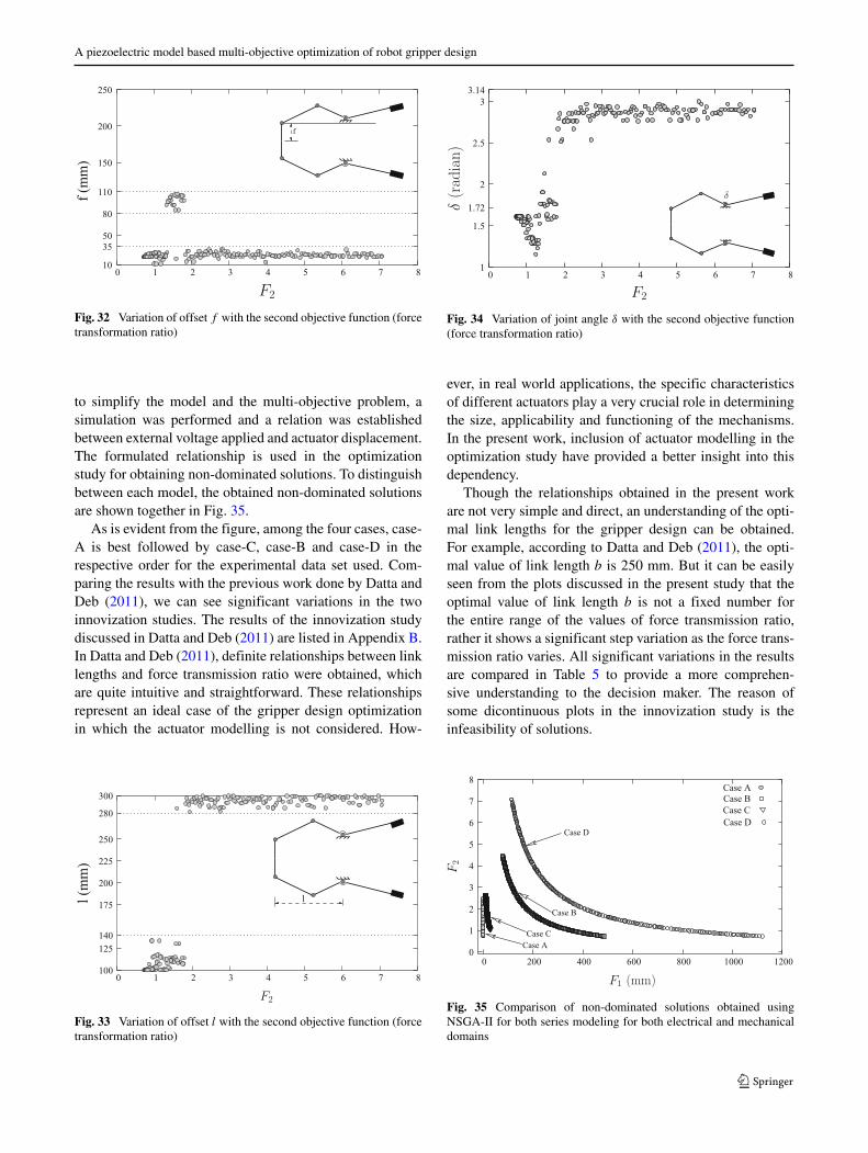
Figure 32 shows the plots of variation of offset f withthe transmission ratio. The value of f varies in two ranges,
b
10
50
110
150
200
220
250
0 1 2 3 4 5 6 7 8
b (
mm
)
Fig. 29 Variation of link length b with the second objective function(force transformation ratio)
c
100
150
200
250
300
0 1 2 3 4 5 6 7 8
c (m
m)
Fig. 30 Variation of link length c with the second objective function(force transformation ratio)
viz. between (10-35) mm and (80-100) mm. Apart from thevalues of force transformation ratio between 1.4 - 1.6, thevalue of link offset f should lie between (10-35) mm for thewhole range of force transmission ratio.
Figure 33 shows that link offset l also lies in two regions.For a low force transformation ratio, l must be fixed between(100 - 140) mm. However, for a higher value of force trans-formation ratio it must be fixed between 280 mm - 300 mm.Figure 34 depicts that joint angle (δ) must be increased withthe increase in force transformation ratio.
5 Discussions and analysis of results
In the present framework, four different assemblies of actu-ator modelling have been proposed and combined with amulti objective optimization problem to formulate four sep-arate optimization problems. Multi-objective genetic algo-rithm has been used to solve all the four problems. Four dif-ferent sets of non-dominated solutions have been obtainedfrom the multi objective optimization study. For all thefour cases, generalized PZ models are developed. However,
e
0
10
20
30
35
40
50
0 1 2 3 4 5 6 7 8
e (m
m)
Fig. 31 Variation of offset e with the second objective function (forcetransformation ratio)
A piezoelectric model based multi-objective optimization of robot gripper design
f
10
35
50
80
110
150
200
250
0 1 2 3 4 5 6 7 8
f (m
m)
Fig. 32 Variation of offset f with the second objective function (forcetransformation ratio)
to simplify the model and the multi-objective problem, asimulation was performed and a relation was establishedbetween external voltage applied and actuator displacement.The formulated relationship is used in the optimizationstudy for obtaining non-dominated solutions. To distinguishbetween each model, the obtained non-dominated solutionsare shown together in Fig. 35.
As is evident from the figure, among the four cases, case-A is best followed by case-C, case-B and case-D in therespective order for the experimental data set used. Com-paring the results with the previous work done by Datta andDeb (2011), we can see significant variations in the twoinnovization studies. The results of the innovization studydiscussed in Datta and Deb (2011) are listed in Appendix B.In Datta and Deb (2011), definite relationships between linklengths and force transmission ratio were obtained, whichare quite intuitive and straightforward. These relationshipsrepresent an ideal case of the gripper design optimizationin which the actuator modelling is not considered. How-
l
100
125
140
175
200
225
250
280
300
0 1 2 3 4 5 6 7 8
l (m
m)
Fig. 33 Variation of offset l with the second objective function (forcetransformation ratio)
1
1.5
1.72
2
2.5
3
3.14
0 1 2 3 4 5 6 7 8
Fig. 34 Variation of joint angle δ with the second objective function(force transformation ratio)
ever, in real world applications, the specific characteristicsof different actuators play a very crucial role in determiningthe size, applicability and functioning of the mechanisms.In the present work, inclusion of actuator modelling in theoptimization study have provided a better insight into thisdependency.
Though the relationships obtained in the present workare not very simple and direct, an understanding of the opti-mal link lengths for the gripper design can be obtained.For example, according to Datta and Deb (2011), the opti-mal value of link length b is 250 mm. But it can be easilyseen from the plots discussed in the present study that theoptimal value of link length b is not a fixed number forthe entire range of the values of force transmission ratio,rather it shows a significant step variation as the force trans-mission ratio varies. All significant variations in the resultsare compared in Table 5 to provide a more comprehen-sive understanding to the decision maker. The reason ofsome dicontinuous plots in the innovization study is theinfeasibility of solutions.
Case D
Case A
Case B
Case C
0
1
2
3
4
5
6
7
8
0 200 400 600 800 1000 1200
Case D
Case C
Case B
Case A
Fig. 35 Comparison of non-dominated solutions obtained usingNSGA-II for both series modeling for both electrical and mechanicaldomains

R. Datta et al.
Table5
Com
parisonof
results
ofthepresentstudy
with
theprevious
studydone
byDattaandDeb
(2011)
Parameter
DattaandDeb
(2011)
CaseA
CaseB
CaseC
CaseD
Linklength
aUpper
bound
a=
250mm
Step
variation
Nodefiniteresult
Step
variation
a=
250mm
a=
250mm;F
2<
1.8
Variesbetween
a=25
0mm;F
2<
1.8
a=
160mm;F
2>
1.8
197to
250mm
avaries
150to
200mm;F
2,>
1.8
Linklength
bUpper
bound
Nodefiniteresult
Nodefiniteresult
Linevariation
Nodefinite
b=
250mm
Variesbetween
bvaries
from
190to
250mm;F
2<
1.8
Slope
=−3
2.5
Variesbetween
150to
200mm
bvaries
from
130to
160mm;F
2>
1.8
Intercept=
165mm
110to
220mm
Linklength
cLow
erbound
Low
erbound
Low
erbound
Low
erbound
Nodefiniteresult
c=
100mm
c=
100mm
c=
100mm
c=
100mm
Variesbetween100to
150mm
Offsete
Low
erbound
Nodefiniteresult
Nodefiniteresult
Low
erbound
Nodefiniteresult
e=
0mm
evaries
from
10to
20mm;low
erF2
Variesfrom
0to
14mm
e=
0mm
Variesfrom
0to
35mm
evaries
from
40to
50mm;h
igh
F2
Offsetf
f=
37mm
Nodefiniteresult
Nodefiniteresult
Nodefiniteresult
Variesfrom
25to
100mm
fvaries
from
15to
60mm;
f=
50mm
fvaries
from
10TO35
mm;
F2
<1.25
and
F2
>1.8
F2
<1.4and
F2
>1.6
fvaries
from
90to
125mm;
fvaries
from
80to
110mm;
1.25
<F2
<1.8
1.4
<F2
<1.6
Offsetl
Low
erbound
Low
erbound
Step
variation
Upper
bound
Step
variation
l=
100mm
l=
100mm
l=
100mm;F
2<
1.8
l=
300mm
lvaries
from
100to
140mm;F
2<
1.8
l=
300mm;F
2>
1.8
lvaries
from
280to
300mm;F
2>
1.8
Ang
leδ
δ=
1.72
Nodefiniteresult
Nodefiniteresult
Nodefiniteresult
Nodefiniteresult
Variesbetween1.4to
2.2
δvaries
from
1.2to
1.6;
F2
<1.25
Variesbetween2to
2.5
Generaltrendincrease
inδwith
F2
δvaries
from
1.7to
2;1.25
<F2
<1.8
δvaries
from
2.5to
2.8;
F2
>1.8
A piezoelectric model based multi-objective optimization of robot gripper design
On similar lines, for different PZ actuators separateexperiments can be performed to choose the appropriatemodel (out of the four proposed) for the actuator and obtainthe corresponding relations between V and z. Using thechosen actuator model, the optimization study can be per-formed. Furthermore, carrying out the innovization studiesin all the cases can also provide more insight to the decisionmaker in deciding the optimal link lengths and joint anglesfor the gripper based on his/her requirements.
6 Conclusions
The present work tackles the problem of optimizing thedesign of a PZ actuator driven robotic gripper. It considersfour different combinations of series and parallel assem-bly for PZ actuator modelling. The model uses linearizedgoverning equations for PZ actuators and thus reduces thecomputational cost for modelling and optimization study.Relationships between force and voltage with point of actu-ation are considered to derive the governing equations ofthe model. The relationships are obtained by modeling theconnectors of the stack assembly as a connector spring. Thederived equations are integrated with a modified formula-tion of an existing multi-objective design problem of a robotgripper, originally proposed in Osyczka (2002), and solvedin the present work.
The robot gripper problem consists of non-linear, non-convex and multi-modal constraints and objective functions.The problem is solved with a evolutionary multi-objectiveoptimization procedure (EMO). Four different sets of non-dominated solutions are obtained from the optimizationstudy. The obtained non-dominated solutions from eachcases are plotted separately. An Innovization study is car-ried out for each case to establish a meaningful relationshipbetween force and actuator displacement with the Pareto-optimal solutions. The four non-dominated solutions arejointly plotted to select the best arrangement. The study willbe further extended to other smart actuators.
Acknowledgments Part of the work has been jointly supported bythe Department of Biotechnology, India and the Swedish Governmen-tal Agency for Innovation Systems.
Appendix A: Problem formulation
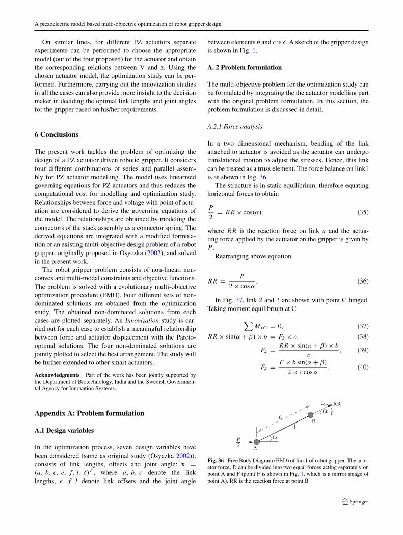
A.1 Design variables
In the optimization process, seven design variables havebeen considered (same as original study (Osyczka 2002)),consists of link lengths, offsets and joint angle: x =(a, b, c, e, f, l, δ)T , where a, b, c denote the linklengths, e, f, l denote link offsets and the joint angle
between elements b and c is δ. A sketch of the gripper designis shown in Fig. 1.
A. 2 Problem formulation
The multi-objective problem for the optimization study canbe formulated by integrating the the actuator modelling partwith the original problem formulation. In this section, theproblem formulation is discussed in detail.
A.2.1 Force analysis
In a two dimensional mechanism, bending of the linkattached to actuator is avoided as the actuator can undergotranslational motion to adjust the stresses. Hence, this linkcan be treated as a truss element. The force balance on link1is as shown in Fig. 36.
The structure is in static equilibrium, therefore equatinghorizontal forces to obtain
P
2= RR × cos(α). (35)
where RR is the reaction force on link a and the actua-ting force applied by the actuator on the gripper is given byP .
Rearranging above equation
RR = P
2 × cosα. (36)
In Fig. 37, link 2 and 3 are shown with point C hinged.Taking moment equilibrium at C
∑MxC = 0, (37)
RR × sin(α + β) × b = Fk × c, (38)
Fk = RR × sin(α + β) × b
c, (39)
Fk = P × b sin(α + β)
2 × c cosα. (40)
IP2 A
a
1
RR
Fig. 36 Free Body Diagram (FBD) of link1 of robot gripper. The actu-ator force, P, can be divided into two equal forces acting separately onpoint A and F (point F is shown in Fig. 1, which is a mirror image ofpoint A). RR is the reaction force at point B

R. Datta et al.
cb
RR
2 3
C
Fig. 37 Free Body Diagram (FBD) of link 2 of robot gripper
A.2.2 Link geometry analysis
From Pythagoras theorem, in Δ ACD (Fig. 38), we get
g2 = (l − z)2 + e2,
g =√
(l − z)2 + e2.
Using cosine law in Δ ABC
cos(α − φ) =(
a2 + g2 − b2
2 × a × g
).
Solving the above equation for α, we get,
α = arccos(a2 + g2 − b2
2 × a × g) + φ.
Again, from cosine law in Δ ABC, for angle (β + φ)
cos(β + φ) =(
b2 + g2 − a2
2 × b × g
).
Solving the above equation for β, we get,
β = arccos
(b2 + g2 − a2
2 × b × g
)− φ.
Also, from Δ ACD we can get
φ = arctan
(e
l − z
).
A.3 Constraints
The gripper configuration is physically constrained at var-ious points, for obtaining the required movement. Thesephysical restrictions can be represented in the formula-tion as the problem constraints.These formulated constraints
Fig. 38 Geometrical construction for the gripper mechanism. In Δ
ACD, g is the hypotenuse distance between point A and point C and φ
is the angle between AC and AD
are multi-modal and non-linear in nature. The formulatedconstraints for the study are discussed in detail as following:
1. At the maximum actuator displacement, the distancebetween both ends of the gripper should be less thanminimal dimension of the object, for proper gripping.
g1(x) = Ymin − y(x, Zmax) ≥ 0. (41)
in the above equation, y(x, z) = 2 × [e + f + c ×sin(β+δ)] denotes the distance between two ends of thegripper and Ymin is the minimal dimension of the objectto be gripped. The parameter Zmax corresponds to themaximum actuator displacement.
2. The distance between gripper ends for maximumactuator displacement (Zmax) should be greater thanzero:
g2(x) = y(x, Zmax) ≥ 0. (42)
3. When the actuator displacement is zero, the distancebetween two ends of the gripper should be greater thanthe maximum dimension object to be gripped.
g3(x) = y(x, 0) − Ymax ≥ 0. (43)
where Ymax denotes the maximum dimension of theobject to be gripped.
4. The maximum range of the displacement of the grip-ping ends of the gripper should be greater than or equalto the distance between the gripping ends correspondingto zero actuator displacement:
g4(x) = YG − y(x, 0) ≥ 0. (44)
where YG is the maximum displacement that gripperends can attain.
5. Geometric constraints for the gripper mechanism can begiven as:
g5(x) = (a + b)2 − l2 − e2 ≥ 0. (45)
The geometric interpretation of constraint g5(x) isshown in Fig. 39.
g6(x) = (l − Zmax)2 + (a − e)2 − b2 ≥ 0. (46)
l
a
b
e
2
Fig. 39 Geometric illustration of constraint g5(x) for robot gripperdesign

A piezoelectric model based multi-objective optimization of robot gripper design
e
b2
a1
Fig. 40 Geometric illustration of constraint g6(x)
The geometric interpretation of constraint g6(x) canbe seen from Fig. 40.
g7(x) = l − Zmax ≥ 0. (47)
6. Minimum force to grip the object should be greater thanor equal to chosen limiting gripping force:
g8(x) = minz
Fk(x, z) − FG ≥ 0, (48)
where FG is the assumed minimal griping force.
A.4 Objective functions
The objective functions for an optimized gripper design,have to be formulated based on link geometry analysis. Theformulated functions used in this optimization study are asfollows:
1. For any gripper mechanism, the most crucial aspect isto ensure a steady firm grip on the object to be gripped.Hence, the first objective function must be formulatedin a way such that this requirement is addressed. Wehave assumed the difference between the maximum andminimum value of gripping force that will be applied
e
l
a b
0
50
100
150
200
250
1 1.05 1.1 1.15 1.2 1.25
a, b
l
e
Lin
k l
ength
s (a
, b, e,
l)
F2
Fig. 41 Variation of link length a, b and offsets e, l with forcetransformation ratio
c
Slope =243.6
2
100
150
200
250
300
1 1.05 1.1 1.15 1.2 1.25
c (m
m)
F
Fig. 42 Variation of offset c with force transformation ratio
on the object during the whole operation, as our firstobjective function.
F1(x) = maxz
Fk(x, z) − minz
Fk(x, z). (49)
2. One of the most desirable characteristic in any mecha-nism, is to have a low energy consumption. In a grippermechanism, lower power consumption can be ensuredby having a higher force transformation ratio. Hence,the second objective function for the present study isformulated as to maximize the force transformationratio of the mechanism. Force transformation ratio inthe initial study was defined as the ratio between theapplied actuating force P and the resulting minimumgripping force at the tip of link c (Osyczka (2002)):
F2(x) = P
minz Fk(x, z). (50)
However, as actuator modelling is taken in consider-ation in the present study, the actuator force P is no
f
10
3750
100
150
200
250
1 1.05 1.1 1.15 1.2 1.25
f (m
m)
F2
Fig. 43 Variation of offset f with force transformation ratio

R. Datta et al.
1
1.5
1.72
2
2.5
3
3.14
1 1.05 1.1 1.15 1.2 1.25
F2
Fig. 44 Variation of joint angle δ with force transformation ratio
longer a constant and varies with actuator displacement.The second modified objective can be defined as
F2(x) = maxz
(P(x, z)Fk(x, z)
). (51)
Appendix B: Previous results
The results of the innovization study done by Datta andDeb (2011) are presented in this appendix. For better under-standing and interpretation of the results, corresponding linklengths, link offsets and joint angle are also shown alongwith the plots. Figure 41 shows the relationships betweenlink lengths a, b and offsets e, l with force transformationratio (F2). It is clear from the figure that a and b must befixed at 250 mm, e must be 100 mm where as l should be 0mm.
Link length c varies with F2 as a straight line with slope= 243.6 and intercept = 0, as shown in Fig. 42. Figures 43and 44 shows that f must be fixed at 37 mm and δ should be1.72 radian.
References
Adriaens H, De Koning W, Banning R (2000) Modeling piezoelectricactuators. IEEE/ASME Transactions on Mechatronics 5(4):331–341
Anton SR, Sodano HA (2007) A review of power harvesting usingpiezoelectric materials (2003–2006). Smart Mater Struct 16(3):R1
Benjeddou A (2000) Advances in piezoelectric finite element mod-eling of adaptive structural elements: a survey. Comput Struct76(1):347–363
Bicchi A, Kumar V (2000) Robotic grasping and contact: A review.In: ICRA. Citeseer, pp 348–353
Chee CY, Tong L, Steven GP (1998) A review on the modellingof piezoelectric sensors and actuators incorporated in intelligentstructures. J Intell Mater Syst Struct 9(1):3–19
Ciocarlie M, Allen P (2010) Data-driven optimization for underactu-ated robotic hands. In: IEEE International Conference on Roboticsand Automation (ICRA), 2010. IEEE, pp 1292–1299
Ciocarlie M, Hicks FM, Holmberg R, Hawke J, Schlicht M, Gee J,Stanford S, Bahadur R (2014) The velo gripper: A versatile single-actuator design for enveloping, parallel and fingertip grasps. Int JRobot Res 33(5):753–767
Croft D, Devasia S (1998) Hysteresis and vibration compensation forpiezoactuators. J Guid Control Dyn 21(5):710–717
Datta R, Deb K (2011) Multi-objective design and analysis of robotgripper configurations using an evolutionary-classical approach.In: Proceedings of the 13th annual conference on Genetic andevolutionary computation. ACM, pp 1843–1850
Deb K, Pratap A, Agarwal S, Meyarivan T (2002) A fast and eli-tist multiobjective genetic algorithm: Nsga-ii. IEEE Trans EvolComput 6(2):182–197
Deb K, Srinivasan A (2006) Innovization: Innovating design principlesthrough optimization. In: Proceedings of the 8th annual conferenceon Genetic and evolutionary computation. ACM, pp 1629–1636
Goldfarb M, Celanovic N (1999) A flexure-based gripper for small-scale manipulation. Robotica 17(02):181–187
Gu G-Y, Zhu L-M, Su C-Y, Ding H (2013) Motion control of piezo-electric positioning stages: modeling, controller design, and exper-imental evaluation. IEEE/ASME Transactions on Mechatronics18(5):1459–1471
Harres D (2013) MSP430-based robot applications: a guide to devel-oping embedded systems. Newnes
IEEE standard (1987) I.E.E.E. Standard on Piezoelectricity: An Amer-ican National Standard. I.E.E.E. Transactions on sonics and ultra-sonics. IEEE
Irschik H (2002) A review on static and dynamic shape control ofstructures by piezoelectric actuation. Eng Struct 24(1):5–11
Jain A, Datta R, Bhattacharya B (2015) Unified minimalistic mod-elling of piezoelectric stack actuators for engineering applications.In: Robot Intelligence Technology and Applications 3. Springer,pp 459–473
Krenich S (2004) Multicriteria design optimization of robot grippermechanisms. In: IUTAM Symposium on Evolutionary Methods inMechanics. Springer, pp 207–218
Low T, GuoW (1995) Modeling of a three-layer piezoelectric bimorphbeam with hysteresis. J Microelectromech Syst 4(4):230–237
Osyczka A (2002) Evolutionary algorithms for single and multicriteriadesign optimization. Physica-Verlag, Heidelberg
Osyczka A, Krenich S, Karas K (1999) Optimum design of robotgrippers using genetic algorithms. In: Proceedings of the ThirdWorld Congress of Structural and Multidisciplinary Optimization(WCSMO), Buffalo, New York, pp 241–243
Perez R, Agnus J, Clevy C, Hubert A, Chaillet N (2005) Mod-eling, fabrication, and validation of a high-performance 2-dofpiezoactuator for micromanipulation. IEEE/ASME Transactionson Mechatronics 10(2):161–171
Reddy PVP, Suresh VS (2013) A review on importance of universalgripper in industrial robot applications
Saravanan R, Ramabalan S, Ebenezer N, Dharmaraja C (2009) Evolu-tionary multi criteria design optimization of robot grippers. ApplSoft Comput 9(1):159–172
Shikhar P (2014) Analysis and design optimization of a seven linkrobot gripper with an integrated actuation system. Master’s thesis,IIT Kanpur
Tzen J-J, Jeng S-L, Chieng W-H (2003) Modeling of piezoelec-tric actuator for compensation and controller design. Precis Eng27(1):70–86
Zubir MNM, Shirinzadeh B, Tian Y (2009) Development of a novelflexure-based microgripper for high precision micro-object manip-ulation. Sensors Actuators A Phys 150(2):257–266