a parametric study of reinforced concrete … · elasticity for steel bars and concrete, and...
TRANSCRIPT

International Research Journal of Engineering and Technology (IRJET) e-ISSN: 2395-0056
Volume: 04 Issue: 09 | Sep -2017 www.irjet.net p-ISSN: 2395-0072
© 2017, IRJET | Impact Factor value: 5.181 | ISO 9001:2008 Certified Journal | Page 492
A PARAMETRIC STUDY OF REINFORCED CONCRETE SLABS-ON-GRADE IN INDUSTRIAL BUILDINGS
G. T. Abdel-Rahman1, A. E. El-Ghaly2 and I. G. Shaaban3
1 Associate Professor, Civil Engineering Dept., Benha University, Egypt 2 Assistant Professor, Civil Engineering Department, Benha University, Egypt
3 Visiting Professor, University of Liverpool, UK, (on sabbatical from Benha University, Egypt) --------------------------------------------------------------***----------------------------------------------------------------- ABSTRACT - A parametric study using Non-Linear Finite Element Analysis (NLFEA) was carried out to investigate the response of slabs on grade to industrial trucks with single wheel axles loading. The studied parameters were the load position in relation to slab edges, slab proportions, the reinforcement content, method of reinforcement arrangement, and the modulus of subgrade reaction. The subgrade is represented in the analysis by boundary-spring elements of a non-tension model to simulate the soil-resistance characteristics. The study showed that the load-carrying capacity of slab panels is substantially influenced by panel thickness and, to a lesser extent, the modulus of subgrade reaction. It was found that adequate and practical results can be obtained in case the safety factor of bearing capacity was assigned a value close to 7. In addition, increasing the modulus of the subgrade reaction enhanced the slab strength to some extent. The enhancement diminished with increasing the subgrade modulus beyond 2E-2 N/mm3. Moreover, the reinforcement content had a negligible effect. Applying a linear finite element procedure to the range of slab panels investigated, yielded, in general, acceptable load-carrying capacities as compared to the results of NLFEA. Keywords: Slab-on-grade; modulus of subgrade reaction; Non-Linear Finite Element Analysis; boundary-spring elements; reinforced concrete 1. INTRODUCTION Concrete slabs supported by ground are frequently used in industrial construction to sustain heavy concentrated loads transmitted by handling equipment and vehicle wheels. Due to the damping effect of the soil out of the loaded region, the wheel load acting on the top of a slab on grade, or uniformly distributed over a small circular area, can be modeled by considering an infinitely large Kirchhoff plate resting on a Winkler-type elastic foundation. Within these assumptions, the elastic theory developed earlier by Westergaard [1] provides an approximate solution that is reliable for small loads only. Such slabs on grade are commonly designed using slab thickness design methods such as the Portland Cement Association (PCA) method, the Wire Reinforcement Institute (WRI) method and the Corps of Engineers (COE) method. Based on Westergaard’s theory supplemented by empirical modifications [1], all these methods consider a slab on grade as a homogeneous, isotropic, and elastic infinite slab resting on a Winkler subgrade that exerts, at all points, a vertical reactive pressure proportional to the slab deflection. Westergaard’s solutions are inadequate particularly for the edge and corner loading conditions [2]. Al-Nasra and Wang [3] investigated the response of warped plain concrete slabs on grade to edge and corner loading, where the concrete slab was represented by eight-node brick element, and the isolation joints and subgrade were represented by non-tension spring elements. Using rectangular thick-plate model, Fwa et al. [4] extensively investigated the limitations of Westergaard’s solutions. The Concrete Society Technical Report TR34 [5], in its 3rd edition, covered the design of concrete ground-supported slabs containing fibres, both steel and synthetic, as an alternative to mesh reinforcement. ACI Committee 360 [6] suggested superior attention to be devoted to modelling the subgrade along with the slab discontinuities such as cracks and fiber reinforcement, to develop a reliable design procedure for slabs on grade; an objective that may be achieved utilizing a sophisticated non-linear finite element approach. Non-linear finite element approaches for the analysis of slabs on grade either reinforced with steel mesh only or those included steel and polypropylene fibers were also reported in the literature [7]. Barros and Figueiras [8] developed a constitutive model for material non-linear analysis of reinforced concrete slabs supported on soil, taking the energy absorption capacity provided by reinforcement into account in the material constitutive relationship. The soil non-linear behaviour was simulated by springs on orthogonal direction to the slab. The loss of contact between the slab and the soil was accounted for. Meda et al. [9] modeled steel-fiber-reinforced concrete slabs on grade using nonlinear fracture mechanics finite element based on both smeared and discrete crack models. In their experimental and theoretical study of the structural behaviour of plain concrete slabs under step loading conditions,

International Research Journal of Engineering and Technology (IRJET) e-ISSN: 2395-0056
Volume: 04 Issue: 09 | Sep -2017 www.irjet.net p-ISSN: 2395-0072
© 2017, IRJET | Impact Factor value: 5.181 | ISO 9001:2008 Certified Journal | Page 493
Alani et al. [10] compared the results with theoretical values derived using available design codes. They showed a notable difference between the test results and the theoretical values. Radi and Maida [11] developed a simplified method for the calculation of the load-carrying capacity of FRC slabs on grade. The results were in reasonable agreement with previously developed models in literature. Øverli [12] captured the non-linear behaviour of the slab on grade using a nonlinear finite element ready package DIANA. The soil was modelled as a non-tension bedding while the concrete was modeled as a smeared crack approach. The results showed that drying shrinkage can cause severe cracking in slabs on grade. Briaud et al. [13] recently presented a new method using a spread sheet called TAMU-SLAB to design stiffened slabs on grade considering enough beam depth to achieve stiff ground beam to resist the applied bending moment and shear force. In the current research, a parametric study was carried out to investigate the structural response of industrial slab on grade to lift-trucks with single wheel axle loading. The studied parameters were the load position in relation to slab edges, slab proportions, reinforcement content and its method of arrangement, and the modulus of subgrade reaction. Based on the published literature on analytical and numerical methods, the authors decided to further develop a non-linear finite element analysis; NLFEA. The model was developed earlier by the first author [14] for plane stress and plate bending problems. The subgrade was represented by boundary-spring elements of a non-tension feature to simulate the soil-resistance characteristics. The numerical results were compared with the predicted response using the linear finite element formulations incorporated in commercial software packages to assess their application range and practicality. 2. NON-LINEAR FINITE ELEMENT ANALYSIS 2.1 Finite element model A well-correlated computer code for NLFEA, modeling reinforced concrete plates and membranes, was presented elsewhere [14]. This program was utilized in the current investigation. The code was modified to include boundary-spring elements to simulate the subgrade as a set of orthogonal springs. The vertical spring is a non-tension one that is capable of resisting compressive forces only, permitting the slab lift-off. The horizontal springs were assigned insignificant stiffness to fulfill in-plane stability. The stiffness of the subgrade depends on the slab proportions, load level, degree of soil compaction, and type of soil [12]. However, values obtained from a plate load test are normally adopted in design. Larralde and Chen [15] considered the stiffness to be a non-linear function of the slab deflection. The effect is negligible, as the deflections were small values. Herein, a linear subgrade modulus has been assumed. The stiffness matrix for the subgrade springs, Ksub is given by: Kx 0 0
Ksub = | 0 Ky 0 | (1)
0 0 Kz
Where Kx and Ky are the stiffness of the horizontal springs, and Kz is the stiffness of the vertical spring. A 4-node quadrilateral plate-bending element with 20 degrees of freedom was selected to idealize the slab. A layered approach was adopted as shown in Figure 1. The concrete characteristics were specified for each layer through the thickness, and the reinforcing steel was presented as a smeared layer of equivalent thickness with uni-axial strength and rigidity properties. The response of each concrete or steel layer was represented at the Gauss integration points, where a 2x2-integration rule was used. Perfect bond between steel and concrete was assumed to avoid local effects inconsistent with the smeared-crack approach adopted here. 2.2 Analysis procedure The numerical solution technique adopted for the analysis was an incremental load procedure. Incidentally, this procedure was applied to the sustained loads whereas the own weight of the slab was considered once at the outset. For each load increment, the iterative solution was performed in which the stiffness was reformulated every so often. The stiffness of vertical boundary elements that were in tension was reduced to zero. The iterative process was carried on until the specified convergence criterion was satisfied. The convergence criterion used was based on the iterative nodal displacements. Euclidean norm of the iterative nodal displacements was compared with the given tolerance. The convergence tolerance varied from 1% - 2%.

International Research Journal of Engineering and Technology (IRJET) e-ISSN: 2395-0056
Volume: 04 Issue: 09 | Sep -2017 www.irjet.net p-ISSN: 2395-0072
© 2017, IRJET | Impact Factor value: 5.181 | ISO 9001:2008 Certified Journal | Page 494
3. PARAMETRIC INVESTIGATION A parametric study was conducted to investigate the theoretical behaviour of industrial slab on grade. The studied parameters were the load position in relation to slab edges, slab proportions, the reinforcement content, the method of reinforcement arrangement, and modulus of subgrade reaction. The study covers slab thickness between 150 mm and 300 mm, slab side-length ranges between 3.0m and 6.0m, and moduli of subgrade reaction between 5E-3 N/mm3 and 5E-2 N/mm3. The effectiveness of marginal thickening of slabs on grade was also examined. The panels were subjected to two-point concentrated loading representing single wheel axles of lift-trucks with wheel spacing of 1000 mm. High-grade steel reinforcement with yield strength, fy of 360 MPa was used. Concrete cube strength, fcu was set at 20 MPa. Moduli of elasticity for steel bars and concrete, and modulus of rupture for concrete, were assumed as 200 KN / mm2, 19.7 KN / mm2 and 2.68 MPa, respectively. Slab panels details are summarized in Table (1). The slab panels were modelled for the finite element analysis using equal-size quadrilateral elements of 0.50m side length. The individual element was discretized into ten layers of concrete for integration through the thickness. The in-plane reinforcement was modelled in a smeared method. Typical mesh and element discretization are shown in Figure 1.

International Research Journal of Engineering and Technology (IRJET) e-ISSN: 2395-0056
Volume: 04 Issue: 09 | Sep -2017 www.irjet.net p-ISSN: 2395-0072
© 2017, IRJET | Impact Factor value: 5.181 | ISO 9001:2008 Certified Journal | Page 495
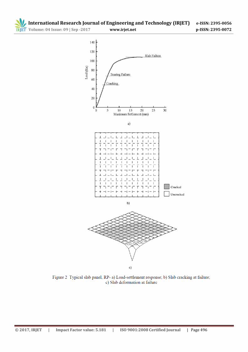
3.1 Typical slab panel A typical panel was selected to represent average industrial slab conditions. A square slab of 6.0m side-length and 0.15m thick, and subjected to corner loading was analysed. The slab was reinforced with a top mesh of 5Y8/m’, representing the cross-sectional area of steel required for shrinkage and temperature variation, using the subgrade drag theory. Concrete cover for reinforcing bars was taken as 50 mm to avoid plastic settlement cracking. Modulus of subgrade reaction was
assumed 2E-2 N/mm3. The analytical results including the load-settlement response, slab cracking and deformation, and slab bending moments at failure are discussed below. Figure 2 (a) exhibits the load-maximum settlement response of the typical slab panel; RP. The response was virtually linear up to 85% of the failure load, and uninterrupted by the concrete cracking that initiated at 45% of the failure load. A close scrutiny of the results indicated that the cracks were not deep enough to influence the integrity of the panel. Moreover, the cracking was local where, at failure, the cracked region is shown in Figure 2 (b) to represent 9% of the slab panel. Thereafter, a distinct non-linear response was exhibited reflecting the accelerated deterioration of the panel up to failure. Yielding of reinforcing mesh occurred just prior to failure. The analytical failure load, P
f for the panel was 108.0 KN.
Maximum settlement was 20.1 mm. The load-carrying capacity for slab on grade analysed using linear finite element approach is limited by bearing capacity of the subgrade. According to Bowles [16], the allowable bearing capacity, qa is related to the modulus of subgrade reaction,
Kz as follows:
Kz = 40 Fqa KN / m3 (2)
Where F is a safety factor The equation is based on a maximum settlement of about 25.0 mm. In this research, the factor of safety is assigned an upper-bound value of 5. Accordingly, the load at bearing failure; qa = 100 KN / m2, is shown in Figure 2 (a) to be 68.0 KN. The ratio of the slab failure load Pf, to the service load at bearing failure Pb, representing the margin of safety against slab failure, was 1.59 (Table 1). The margin as such is insufficient, where it is commonly considered as minimum as 2.0. It is pertinent that the loading nature for industrial slabs on grade, for instance the dynamic effect associated with handling equipment, has a significant influence on the value assigned for this safety factor. Therefore, it was decided to suggest a value close to 7 as a safety factor of bearing capacity to be used in Equation 2 instead of the commonly used value of 5 in order to enhance the results (Pf / Pb ratio).
The slab deformation at failure shown in Figure 2 (c) reveals the anticipated behaviour that maximum settlement takes place under the applied load at the slab corner. The shaded zone represents the lifted-off part of the panel. At failure, this zone approached 49% of the slab panel pointing out the significance to simulate the subgrade using non-tension boundary-spring elements. Furthermore, this finding disputes the design criterion that allows inspecting the bearing pressure on an average basis. Average settlement at the panel failure was 0.442 mm, indicating an average bearing stress of about 9.0 KN/m2. Referring to Figure 3, the distribution of bending moments in both directions indicates that the effect of loading was confined. The maximal moments at failure represent the flexural strength of the typical panel, RP. The exhibited strength was considered very large in view of the reinforcement content provided in the panel. Ultimate negative (-ve) moment was 32.07 KN.m / m’ corresponding to 7.85 KN.m / with a ratio of 4.09. These results may support the common practice that allows providing top reinforcement in slabs on grade based only on shrinkage requirements whereas the loading characteristics are included in thickness design.
International Research Journal of Engineering and Technology (IRJET) e-ISSN: 2395-0056
Volume: 04 Issue: 09 | Sep -2017 www.irjet.net p-ISSN: 2395-0072
© 2017, IRJET | Impact Factor value: 5.181 | ISO 9001:2008 Certified Journal | Page 496

International Research Journal of Engineering and Technology (IRJET) e-ISSN: 2395-0056
Volume: 04 Issue: 09 | Sep -2017 www.irjet.net p-ISSN: 2395-0072
© 2017, IRJET | Impact Factor value: 5.181 | ISO 9001:2008 Certified Journal | Page 497
3.2 Comparative results A comparative study has been achieved by varying one of the parameters: loading position, slab thickness, slab proportions, reinforcement content and position, and modulus of subgrade reaction, at a time while keeping the rest constant at selected reference values, see Table (1). The values assigned for the parameters of the typical slab panel, RP, are regarded as reference values in the following comparison. 3.3 Effect of loading arrangement Referring to Table (1) for results on Series A, the indicated load-carrying capacities, whether based on slab failure or bearing failure criterion, evince that the design of industrial slabs on grade should be based on corner loading condition. It is noted that the PCA and WRI methods are intended for interior loading cases, while the COE method is intended for edge or joint loading cases with joint transfer coefficient of 0.75 [6]. The ratio of the slab failure load, Pf to the load at bearing failure, Pb, based on Equation 2, ranged from 1.51 to 1.76.
Accepting a margin of safety against slab failure of 2.0, the load-carrying capacities for the panels in Series A were defined by a mode of slab failure and not by subgrade failure. Some practicing engineers examine the bearing stress on an average basis. However, the average settlement of the panel loaded centrally, LP3C of -1.524 mm quite dispute this concept. The average settlement as such indicates that, at failure, the region of the slab panel in contact with the subgrade is minimal. Maximum settlement of the panel, LP3C is shown in Figure 4(a) to lessen by 50%.

International Research Journal of Engineering and Technology (IRJET) e-ISSN: 2395-0056
Volume: 04 Issue: 09 | Sep -2017 www.irjet.net p-ISSN: 2395-0072
© 2017, IRJET | Impact Factor value: 5.181 | ISO 9001:2008 Certified Journal | Page 498
3.4 Effect of slab thickness Increasing the panel thickness was shown to enhance its load-carrying capacity in an accelerating rate, Figure 4 (b). For the panel TH30, doubling the panel thickness resulted in an increase of 167% in the failure load, P f. The increase was 78% for the panel TH1.50 that was marginally thickened by 50%. Increasing the thickness of the panel margin appears to be more effective as it enhanced not only the failure load of the panel, Pf but also the load at bearing failure, Pb. The ratio Pf / Pb was 1.87 for the panel TH30, compared to 2.06 for the panel TH1.50. For isolation joints that have no provision for load transfer, thus, it is preferred to thicken the panel margin and then taper it to the required thickness. 3.5 Effect of slab proportions Referring to Figure 4(c), the load-settlement responses of the panels were essentially comparable regardless of the panels’ proportions. Identical results were recorded for both of the cracking strength and the load-carrying capacity of the slab panels. The comparison between the loads at bearing failure indicates insignificant reduction of 6% in the sustained load for the panel SL300. As shown in Table (1), the margin of safety against the slab failure, referred to by the ratio P f / Pb, ranges from 1.59 and 1.69. The unique discrepancy recorded between the results of Series C was the average settlement at failure. The results presented in Table (1) reveal that the panel lifting-off gets distinct as the panel proportions decrease. The average settlement of the panel SL300 was -1.361 mm at failure. 3.6 Effect of reinforcement content and arrangement A close inspection of the results of Series D demonstrates that reinforcement does not prevent cracking, nor does it add significantly to the load-carrying capacity of industrial slabs on grade. The structural response including the cracking load, load-carrying capacity, and panel deformations, is shown in Figure 4 (d) unchanging for panels provided with various contents of top reinforcement. Nevertheless, it is recommended that top mesh reinforcement is provided to control width of surface cracks. Also, the coincidence of behaviours shown in Figure 4 (d) for the panels PLAIN and RB8 evinces that bottom reinforcement was ineffective for corner loading condition. Further study is required to review the effectiveness of bottom reinforcement in panels under different loading patterns with particular reference to central loading. On the other hand, the ratio Pf/ Pb is 1.59 for panels reinforced with top mesh, whereas it is 1.41 for unreinforced panels, Table (1). 3.7 Effect of modulus of subgrade reaction Referring to Table (1) for results of Series E, increasing the modulus of subgrade reaction, Ko enhances the load-carrying capacity of the panel. The rate of enhancement decreases significantly with increasing Ko beyond 2E-2 N/mm3, disputing the steady rate that the aforementioned slab thickness design methods permit to reduce the slab thickness as the modulus of subgrade reaction increases. The failure load, Pf decreased by 45% as Ko decreased to 5E-3 N/mm3, whereas it increased by 11% as Ko increased to 5E-2 N/mm3, Table (1). The ratio Pf / Pb, ranged from 2.22 to 1.21 as Ko increased from 5E-3 to 5E-2 N/mm3. Practically, the bearing failure criterion can be accepted as a design basis only for the slab panels K0.5 and K1.0. Incidentally, these panels were failed prior to concrete cracking. At a particular loading level, the panels’ settlement decreased with increasing Ko, Figure 4 (e). Al-Nasra and Wang [3] reported that the increase in the modulus of subgrade reaction decreases both the upward and downward deflections. Average settlements shown in Table (1) agree with this finding. 4. COMPARISON WITH LINEAR FINITE ELEMENT ANALYSIS Most practicing engineers employ a linear finite element procedure incorporated in commercial software packages to analyze slabs on grade. Obviously, the assumption of a fully supported slab by the subgrade is maintained in such a procedure. No investigation has been reported in literature on the application range of this method of analysis. In the following, the applicability of the linear finite element analysis FEA is discussed in brief through a comparison of its results with those based on non-linear finite element analysis. The comparison considered the load-carrying capacity and the maximum bending moment. Referring to Table (1), the load-carrying capacity of the slab panels, Pl is defined on the basis of the bearing failure criterion. As shown, the load Pl is comparable to the corresponding one resulting from the non-linear analysis, Pb for all but the panel K5.0 to which the linear analysis yields Pl of 1.27 Pb. The load-settlement responses shown in Figure 4 justify the overall coincidence obtained between the results. The linear response is shown in Figure 4 to essentially last beyond the bearing failure as defined by Equation 2 for all the panels excluding K5.0. On the contrary, the ratio Pf / Pl expressing a safety factor is not in general adequate. The ratio ranges between 0.95 and 2.11 with an average of 1.61. Once more, poorest results were attained at high values of modulus of subgrade reaction.

International Research Journal of Engineering and Technology (IRJET) e-ISSN: 2395-0056
Volume: 04 Issue: 09 | Sep -2017 www.irjet.net p-ISSN: 2395-0072
© 2017, IRJET | Impact Factor value: 5.181 | ISO 9001:2008 Certified Journal | Page 499
As far as the critical bending moments are concerned, the linear finite element analysis resulted in insignificant bending moments, Ml for which the reinforcement mesh provided is plentiful. Figure 5 illustrates the ratio of the maximum bending moment at panel failure, Mf to the maximum bending moment at bearing failure, Ml for both (-ve) and (+ve) moments, (refer to Figure 1 for sign convention of bending moments). The ratio Mf / Ml denotes the safety factor for the panel capacity in flexure. The ratio for (-ve) bending moments is shown to be abundant except for the slab panel K0.5. On the contrary, (+ve) moments’ ratios were in general insufficient with few exceptions. The least ratio of 1.14 was obtained for the panel loaded centrally, LP3C. Provision of bottom mesh reinforcement is anticipated to remarkably improve the results even with minimum reinforcement content. The ratio of Mf / Ml for (+ve) moments was enhanced by 86% for the panel RTB8 whereas the ratio of Pf /Pl remained unchanging. The results of the slab panels PLAIN and RB8 evince that the influence of bottom reinforcement is essentially dependent on the amount of top reinforcement.
5. CONCLUSIONS Based on the study presented herein, the following conclusions can be drawn:

International Research Journal of Engineering and Technology (IRJET) e-ISSN: 2395-0056
Volume: 04 Issue: 09 | Sep -2017 www.irjet.net p-ISSN: 2395-0072
© 2017, IRJET | Impact Factor value: 5.181 | ISO 9001:2008 Certified Journal | Page 500
1- Load-carrying capacity of slabs on grade is normally defined by bearing capacity of the subgrade. Results of the service load at bearing failure; Pb approached the slab failure loads; Pf showing insufficient Pf/ Pb ratio. In the practical range of subgrade modulus, adequate results are expected in case the safety factor of bearing capacity is assigned a value close to 7. 2- Slab thickness has a dominant effect on the results of load-carrying capacity. Increasing the slab thickness, whether uniformly, or marginally, enhances its capacity in an accelerating rate. As regards the cost aspect, marginal thickening of slabs on grade at isolation joints is more effective. 3- Reinforcement has an insignificant influence on the structural response including the cracking strength, load-carrying capacity, and deflection magnitude and sense of slabs on grade. It is sufficient to provide the steel reinforcement on the basis of serviceability requirements. 4- To some extent, increasing the modulus of subgrade reaction enhances the slab strength. The enhancement diminishes with increasing the subgrade modulus beyond 2E-2 N/mm3, disputing the design methods that permit to reduce the slab thickness in a steady mode as the subgrade modulus increases. 5- Linear finite element analysis yields acceptable load-carrying capacities as compared to the results of NLFEA. Essentially, a typical load-settlement response lasts linear beyond the bearing failure criterion set by Equation 2.

International Research Journal of Engineering and Technology (IRJET) e-ISSN: 2395-0056
Volume: 04 Issue: 09 | Sep -2017 www.irjet.net p-ISSN: 2395-0072
© 2017, IRJET | Impact Factor value: 5.181 | ISO 9001:2008 Certified Journal | Page 501
REFERENCES [1] H. M. Westergaard, “New formulas for stresses in concrete pavements of airfields”, Trans. ASCE 113 (1948), 425–
444. [2] A. M. Ioannides, E.J. Barenberg and M.R. Thompson, 1985. “Finite Element Model with Stress Dependent Support.”
Transportation Research Record 954, Nat. Res. Council, Washington, D.C. [3] M. Al-Nasra, and L.R. Wang, 1994. “Parametric Study of Slab-on-Grade Problems due to Initial Warping and Point
Loads.” ACI Structural Journal, V. 91, No. 4, pp. 198-210.
International Research Journal of Engineering and Technology (IRJET) e-ISSN: 2395-0056
Volume: 04 Issue: 09 | Sep -2017 www.irjet.net p-ISSN: 2395-0072
© 2017, IRJET | Impact Factor value: 5.181 | ISO 9001:2008 Certified Journal | Page 502
[4] T.F. Fwa, X.P Shi and S.A. Tan, 1996. “Analysis of Concrete Pavements by Rectangular Thick-Plate Model.” ASCE Journal of Transportation Engineering, V. 122, No. 2, pp. 146-154.
[5] The Concrete Society, Technical Report 34, 2003, “Concrete industrial ground floor slabs – a guide to their design and construction”, 3rd ed.
[6] ACI Committee 360, 2010 “Guide to Design of Slabs-on-Ground” ACI 360R-10, Manual of Concrete Practice, 72 pp. [7] A. M Alani and M Aboutalebi, 2102, “Analysis of the subgrade stiffness effect on the behaviour of ground-
supported concrete slabs”, Structural Concrete 13 (2012), No. 2, pp. 102-108, DOI: 10.1002/suco.201100043. [8] J.A. Barros and J.A Figueiras, 2001, “Model for the Analysis of Steel Fibre Reinforced Concrete Slabs on Grade”,
Computers and Structures, Vol. 79, pp. 97-106. [9] A. Meda, G.A Plizzari and P Riva, 2004, “Fracture Behaviour of SFRC Slabs on Grade,” Materials and Structures, Vol.
37, July 2004, pp. 405-411. [10] A. M. Alani, J Rizzuto, D Beckett, and M Aboutalebi, 2014, “Structural behaviour and deformation patterns in
loaded plain concrete ground-supported slabs”, Structural Concrete Vol. 15, No. 1, pp. 81-93, DOI: 10.1002/suco.201300043
[11] E. Radi and P.D Maida, 2014, “Analytical Solution for Ductile and FRC Plates on Elastic Ground Loaded on A Small Circular Area”, Journal of Mechanics of Materials and Structures, Vol. 9, No. 3, pp. 313-331, dx.doi.org/10.2140/jomms.2014.9.313
[12] J Øverli, 2014, “Experimental and Numerical Investigation of Slabs on Ground Subjected to Concentrated Loads”, Central European Journal of Engineering, Vol. 4, No. 3, March 2014, pp. 210-225.
[13] J.L Briaud, R Abdelmalak, X Zhang, and C Magbo, 2016, “Stiffened Slab-On-Grade on Shrink-Swell Soil: New Design Method,” ASCE, Journal of Geotechnical Geo-environmental Engineering, Vol. 142, No. 7, pp. 04016017: 1-12.
[14] G. T Abdel-Rahman, 1997. “Non-Linear Finite Element Analysis of Reinforced Concrete” CERM, Al-Azhar University, V. 19, No. 4, pp. 543-560.
[15] J Larralde and W.F. Chen, 1987. “Estimation of Mechanical Deterioration of Highway Rigid Pavements.” ASCE Journal of Transportation Engineering, Vol. 113, No. 2, pp. 193-208.
[16] J.E. Bowles, 1982. “Foundation Analysis and Design.” 3rd edition. Mcgraw-Hill, London, 816 pp.