a p l i e d m echan e ournal of lied j mechanical engineering · ournal of lied j mechanical...
TRANSCRIPT

Research Article Open Access
Namata, J Appl Mech Eng 2016, 5:4 DOI: 10.4172/2168-9873.1000213
Case Report Open Access
Journal of Applied Mechanical EngineeringJo
urna
l of A
pplied Mechanical Engineering
ISSN: 2168-9873
Volume 5 • Issue 4 • 1000213J Appl Mech EngISSN:2168-9873 JAME, an open access journal
*Corresponding author: Namata S, KMBB-CET, Biju Patnaik University ofTechnology, Orissa, India, Tel: +61 2 9514 2000; E-mail: [email protected]
Received March 24, 2016; Accepted April 25, 2016; Published April 30, 2016
Citation: Namata S (2016) Structural Stability Crack Analysis of Thermoplastic Composites. J Appl Mech Eng 5: 213. doi:10.4172/2168-9873.1000213
Copyright: © 2016 Namata S. This is an open-access article distributed under the terms of the Creative Commons Attribution License, which permits unrestricted use, distribution, and reproduction in any medium, provided the original author and source are credited.
Structural Stability Crack Analysis of Thermoplastic CompositesNamata S* KMBB-CET, Biju Patnaik University of Technology, Orissa, India
IntroductionFailure of the engineering structures is caused by cracks, which is
depending on the design and operating conditions that extend beyond a safe size. Cracks present to some extent in all structures, either as a result of manufacturing defects or localized damage in service. The crack growth leads to a decrease in the structural strength. Thus, when the service leading to the failure of the structure. Fracture, the final catastrophic event takes place very rapidly and is preceded by crack growth, which develops slowly during normal service conditions.
It is of particular interest to investigate the structure-property of rubber-rich TPO blends reinforced with rigid nanofillers. The effect of nanoclay additions on the structure and property of rubber-rich TPO blends has been investigated by Mishra et al. [1] and Tjong and Ruan [2] more recently. Mishra et al. [1] prepared the TPO/clay nanocomposites where the TPO contains PP and EPDM with the ratio of 25: 100 by weight. They reported that the nanocomposites exhibit remarkable improvement of tensile and storage moduli over their pristine TPO blend. Tjong and Ruan [2] reported that TPO-based nanocomposites reinforced with 0.1–1.5wt% organically modified clay exhibits enhanced stiffness and tensile strength. Moreover, the fracture toughness of TPO/clay nanocompsites increases with the increasing clay content.
Ananda Kumar Eriki and Ravichandra R have already investigated the spur gear crack propagation path analysis using finite element method [3]. Mubashir Gulzar has studied linear and nonlinear analysis of central crack propagation in polyurethane material [4].
Priscilla L. Chin has studied stress analysis, crack propagation and stress intensity factor computation of a Ti-6Al-4V aerospace bracket using ANSYS and FRANC3D [5].
Backdrop of WorkDuring the past few years, extensive efforts have been devoted to
develop methodologies that permit the prediction of crack failure. As the knowledge related to crack expanded, it becomes clear that in certain cases crack could be treated from the crack propagation point of view. The understanding of the crack initiation and crack propagation behavior has led to an increase in the life of structures subjected to static loading condition. To efficiently utilize mechanical components and structures one would like to avoid crack propagation (CP) which results in fatigue failure. However, because of operating conditions and performance requirements it is not always possible. Thus, prediction of expected crack location and crack propagation behavior are the main objectives for the researchers in this field.
The concept of fracture mechanics developed during the early research which is applicable to linear elastic materials is known as linear elastic fracture mechanics (LEFM). LEFM has been used to estimate work life of engineering components and structures. In this approach, the growth of a crack under static loading is principally controlled by the stress intensity factor (SIF) K, which defines the elastic stress field around the crack tip. The SIF plays a major role in LEFM problems and several methods were proposed to derive it using analytical, experimental and numerical techniques. For general cases SIF can
be obtained from handbooks. The handbook solutions of elementary cases are derived from FE-analysis and are often expressed in analytical formulas. The application of the elementary solutions in the design and sizing process involves and requires engineering judgments in a conservative manner.
In addition, due to the latest research and advancements in computational methods, numerical techniques are also employed in this regard. Finite Element Method (FEM) is most commonly used to estimate the SIF numerically and thus, the CPP can be predicted. In FEM the elements are related mathematically with nodal points and the forces are transmitted through these nodal points. Using singular elements around the crack tip, singularity behavior can be achieved and the SI can be calculated numerically which is used later on for the prediction of the CPP and work life prediction. Thus, the research conducted in this Master thesis, is an attempt to investigate the problem of static crack propagation and failure.
Problem DescriptionCurrently, most of the engineering components and structures
are designed with the trend to continuously increase the overall performance of the components and structures. As a result of this rapid and continuous advancement the designers and researchers have to face a lot of new challenges in terms of reliability and better work life of these engineering components and structures. Thus, need for specialized structural strength analysis for such engineering components and structures has gone from a non-issue to a serious concern over the recent few years.
The rear bumper protector of a four wheeler is meant to protect the bumper from scratches, wear, tear or any physical failure due to accidental loads. Thus the protector is subjected to mostly sudden loading, but these loads come repeatedly in long run of the product lifetime, so crack may develop and may result a failure of the product.
To obtain a well defined Crack Propagation Path (CPP) and the structural strength of the structure, FEA is applied. FEA techniques provide good understanding of crack propagation and structural strength of the structures. With the help of these results the overall performance of the product can be judged with a controlled failure in order to avoid risks, which usually lead to a total and dramatic damage of the product.
Goals and PurposeThe main purpose of this research is to analyse the overall structural
Page 2 of 5
Citation: Namata S (2016) Structural Stability Crack Analysis of Thermoplastic Composites. J Appl Mech Eng 5: 213. doi:10.4172/2168-9873.1000213
Volume 5 • Issue 4 • 1000213J Appl Mech EngISSN:2168-9873 JAME, an open access journal
stability of the product from application point of view through Finite Element Analysis technique using ANSYS13 Workbench. Then Crack propagation analysis to verify it’s work life by providing notches of different radii using the same above technique. To perform all the experiments for three different materials, one is the original material of the product itself and two other optimized materials PP+EOC+ATP, PP+EPDM. Then compare all the results obtained and analyse different results with reference to its material. Thus a comparative study can suggest the most suitable material for the product.
Demonstration of Crack PropagationIn many engineering structures and components cracks are initiated
by different ways. It is important to understand the basic phenomenon associated with the crack initiation process, since these cracks will ultimately lead to failure of the material if they are not detected and recognized. There are various ways of crack initiation but three of them are most important and usually in most engineering applications cracks are initiated due to these three processes as illustrated.
1. Nucleating slip planes
Slip occurs when a material is stressed to the point of plastic deformation. When this happens the planes of crystals actually slip from their original positions leaving slip bands which resemble steps. When the material slips it forms a crack at the point of the intersection of the deformed material and the non-deformed material. If the stress is still applied after the crack is formed it continues to propagate and at some point the material fails.
2. Notches
There seems to be confusion among many engineers between notches and cracks. This is not surprising as the boundary between notch and crack is sometimes blurred, especially under fatigue conditions. However, a notch can be defined as geometric discontinuity which has a definite depth and root radius as demonstrated in Figure 2. Notches always result in areas of stress concentration in a structure, since the surface area of the notch is smaller than the surface area of the rest of the solid; hence, in most cases it is observed that notches are the first part to fail in any structure because of stress concentration effects.
3. Internal defects
Internal defects are a lot like notches in the respect that they cause a stress concentration in the material in which they are inhabited. There are several reasons for internal defects like grain boundaries, concentrations of point defects in the area and defects that occurred during processing. The internal defects are illustrated in Figure 2. In most
cases it has been seen that a material usually fails from a crack generated externally long before it fails from a crack generated internally.
Fracture MechanicsThe term “fracture mechanics” refers to a vital specialization within
solid mechanics in which the presence of a crack is assumed, and quantitative relations between the crack length, the material’s inherent resistance to crack growth, and the stress at which the crack propagates are defined [6-15]. It deals with the behavior of cracked bodies subjected to stresses and strains. These can arise from primary applied loads or secondary self-equilibrating stress fields (e.g. residual stresses). The power of fracture mechanics really lies in the fact that local crack tip phenomena can, to a first order, be characterized by relatively easily measured global parameters, e.g. crack length and nominal global stresses (calculated in the absence of the crack), together with geometry correction factors.
The crack propagation behavior is an important parameter which plays a vital role in the fatigue strength analysis of the structures [16-20]. As long as the load is small enough, the structure will only deform elastically. A crack starts to propagate when the crack driving force is larger than the material resistance. If however, the structure is sensitive to cracking due to e.g. inadequate design, defects from manufacturing, handling or bad quality, materials fracture will occur. There are a number of parameters that affect the crack propagation mechanism i.e., material properties [21-28].
Linear Elastic Fracture Mechanics (LEFM)LEFM principles are used to relate the stress magnitude and
distribution near the crack tip to the remote stresses applied to the cracked component, crack size, crack shape and the material properties of the cracked component The general form of the LEFM equation is given as:
( ) ....2
Iij ij
K fr
σ θπ
= + (2.1)
Where
r = distance from the crack tip
KI = Mode I SIF Figure 1: Plane stress state in a continuum.
Figure 1: Plane stress state in a continuum.
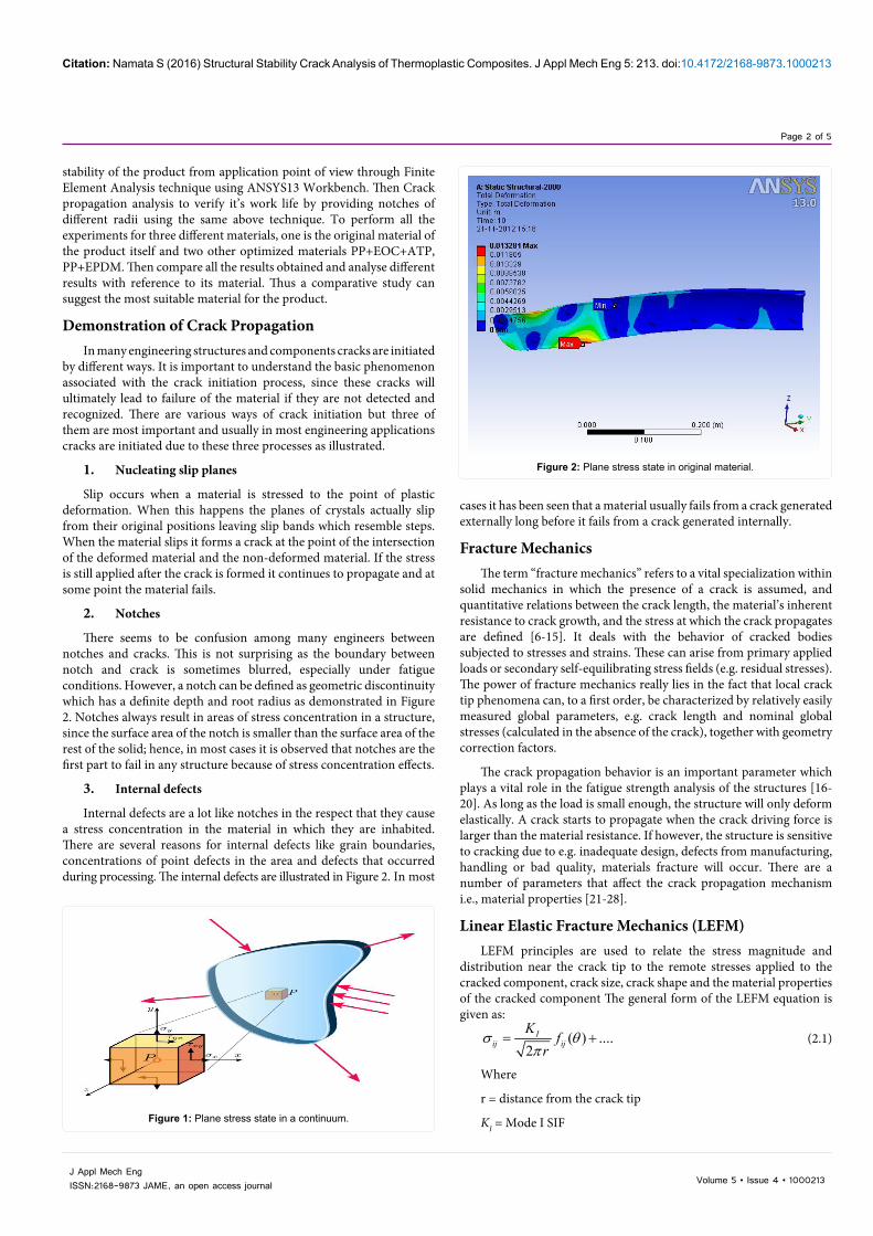
Figure 2: Plane stress state in original material. Figure 2: Plane stress state in original material.

Page 3 of 5
Citation: Namata S (2016) Structural Stability Crack Analysis of Thermoplastic Composites. J Appl Mech Eng 5: 213. doi:10.4172/2168-9873.1000213
Volume 5 • Issue 4 • 1000213J Appl Mech EngISSN:2168-9873 JAME, an open access journal
describes the ability of a material containing a crack to resist fracture. The subscript I denotes mode I crack opening under a normal tensile stress perpendicular to the crack.
Fracture toughness is a quantitative way of expressing the resistance of a material to brittle fracture when a crack is present. It is independent of the size and geometry of the cracked body under certain conditions. The materials with higher values of fracture toughness are more likely to undergo a ductile fracture; however, the materials with low value fracture toughness usually undergo a brittle fracture. The largest crack a structure can sustain under specific residual strength requirements can be predicted through this critical value of the SIF where the crack propagation becomes unstable. The fracture criteria can be expressed as:
K = KIc (2.3)
Plane Stress ConditionA state of plane stress exists when one of the three principal, (σ1,
σ2, σ3) stresses is zero. This usually occurs in structures where one dimension is very small compared to the other two, i.e., the structure is flat or thin. In this case, the stresses are negligible with respect to the smaller dimension as they are not able to develop within the material and are small compared to the in-plane stresses.
Figure 2 demonstrates the plane stress state in a continuum. Therefore, the face of the element is not acted by loads and the structural element can be analyzed as two-dimensional, e.g. thin-walled structures such as plates subject to in-plane loading. The stress tensor can then be approximated by:
00
0 0 0
x xy
ij yx y
σ τσ τ σ
=
The corresponding strain tensor is:
11 12
21 22
33
00
0 0ij
ε γε γ ε
ε
=
In above expression the non-zero ε33 term arises from the Poisson’s effect
Consider a point P in a continuum under a state of plane stress, or plane strain, with stress components,(σx, σy, τxy),and all other stress components equal to zero as shown in Figure 1.
From static equilibrium of an infinitesimal material element at P, the normal stress σn and the shear stress τn on any plane perpendicular to the x-y plane passing through P with a unit vector n making an angle of θ with the horizontal, i.e., cosθ is the direction cosine in the x direction, is given by:
xy
xy
1 1( ) ( ) cos 2 sin 22 21 ( )sin 2 cos 22
n x y x y
n x y
σ σ σ σ σ θ τ θ
τ σ σ θ τ θ
= + + − +
= − − +
Mohr’s circle provides a graphical representation of equation. These equations indicate that in a plane stress or plane strain condition, one can determine the stress components at a point on all directions, i.e., as a function of θ, if one knows the stress components (σx, σy, τxy), on any two perpendicular directions at that point. It is important to remember that we are considering a unit area of the infinitesimal element in the direction parallel to the y−z plane.
fij(θ) = function that represents the stress dependence on θ
LEFM Assumptions LEFM is based on the application of the theory of elasticity to
bodies containing cracks or defects. The assumptions used in elasticity are also inherent in the theory of LEFM: small displacements and general linearity between stresses and strains.
The general form of the LEFM equations is given in equation 2.1. As seen, a singularity exists such that as r, the distance from the crack tip, tends toward zero, the stresses go to infinity. As the yield stress is exceeded, material deforms plastically and a plastic zone is formed near the crack tip. The basis of LEFM remains valid if this region of plasticity remains small in relation to the overall dimensions of the crack and cracked body.
Crack Propagation ModesThere are generally three modes of loading, which involve different
crack surface displacements as shown in Figure 2. The three modes are:
Mode I: Opening or tensile mode (the crack faces are pulled apart)
Mode II: Sliding or in-plane shear (the crack surfaces slide over each other)
Mode III: Tearing or anti-plane shears (the crack surfaces move parallel to the leading edge of the crack and relative to each other.
Stress Intensity FactorThe SIF (K) introduced in equation 2.1, defines the magnitude of
the local stresses around the crack tip. This factor depends on loading, crack size and geometry. It can be expressed in a general form given by
aK afw
σ π =
(2.2)
where,
σ = Remote stress applied to the component
a = crack length
afw
=correction factor that depends on specimen and crack
geometry
Energy Release RateGriffith was the first to propose the energy criterion for fracture,
but Irwin is primarily responsible for developing the present version of this approach. First, the potential energy Π of an elastic body is defined as:
where U is the elastic strain energy stored in the body and W is the potential energy or the work done by external forces. The energy release rate G is defined as the rate of change in potential energy with respect to the crack area.
The energy release rate G is a measure of the energy available for an increment of a crack extension. To define the fracture criteria in an energy consideration the same discussion used for the stress intensity can be employed. An unstable crack growth occurs when the energy release rate reaches a critical value G=GC, where GC is a measure of fracture toughness and can be considered as a material property.
Fracture ToughnessIn materials science, the fracture toughness KIc is a property which

Page 4 of 5
Citation: Namata S (2016) Structural Stability Crack Analysis of Thermoplastic Composites. J Appl Mech Eng 5: 213. doi:10.4172/2168-9873.1000213
Volume 5 • Issue 4 • 1000213J Appl Mech EngISSN:2168-9873 JAME, an open access journal
Result and DiscussionSimulation results for static structural analysis
After performing the simulation in ANSYS for a 2000 N ramped load the results are obtained in the form of deformations and stress distributions. The results obtained from ANSYS are described as follows;
Deformation results
The deformation behaviors obtained from FE analysis for a 2000 N ramped load are compared for the three reference materials. It has been found, that the structural deformation behaviour is non-symmetric. The values obtained are in good acceptable range and the maximum value is found to be 13.281 mm for the original material as shown in Figure 2 and the minimum value is found to be 6.7999 mm for the material PP+EPDM Figure 3.
Stress distribution results
The stress distribution results are obtained in the form of Von-Misses stresses and a maximum value is found to be 30.696 MPa for the material PP+EOC +ATP as shown in Figure 3 and a minimum value is found to be 11.046 MPa for the material PP+EPDM. Like the deformation results, the stress distribution is also non-symmetric and the maximum stresses are found around the strain tensor. It has been observed that the stress distribution behaviour around each strain tensor is consistent. Figures 2 and 3 demonstrate the location of the maximum Von Misses stress and the stress distribution behaviour around the strain tensor Figure 4.
ConclusionThe purpose of this thesis was to study the structural stability and
crack propagation behaviour of the bumper protector structure based on FEA. The FEA is done with ANSYS13. An important aspect of this research was to compare the results from FEA for the three reference materials for five different Notch radiuses. The success in this manner depends both on the evaluation methods of the experiments and accuracy of FE models used in FEA. The crack propagation and static structural analysis is done with ANSYS13. A detailed study concerning different FE models with different geometries based on symmetry assumptions under static loading conditions were performed.
References
1. Mishra JK, Hwang KJ, Ha CS (2005) Preparation mechanical and rheological properties of a thermoplastic polyolefin (TPO)/organoclay nano-composite with reference to the effect of maleic anhydride modified polypropylene as a compatibilizer. Polymer 46 24:1995-2002.
2. Tjong SC, Ruan YH (2008) Fracture behavior of thermoplastic polyolefin/clay nanocomposites. J Applied Polymer Science 110: 864-871.
3. Ananda Kumar E, Member IAENG, Ravichandra R, Member IAENG, Mustaffa ME et al. (2012) Spur gear crack propagation path analysis using finite element method. Proceedings of the international multiconference 2:14-16.
4. Gulzar M (2012) Linear and nonlinear analysis of central crack propagation in polyurethane material - A comparison. Proceedings of the World Congress on Engineering 3: 4-6.
5. Chin PL(2011) Stress analysis crack propagation and stress intensity factor computation of a Ti-6Al-4V aerospace bracket using ANSYS and FRANC3D.
6. Zhu Liao C, Chin Tjong S (2010) Mechanical and fracture behaviors of elastomer-rich thermoplastic polyolefin/SiCp nanocomposites. University of Hong Kong, Tat Chee Avenue, Kowloon Hong Kong. J Nanomaterials.
7. Pook LP, Frost NE, Matsh K (1974) Metal fatigue. Oxford University Press.
8. (1987) ASTM: E1150/87 Standard definitions of terms relating to fatigue. American society for testing and Materials: 1-10.
9. Miller KJ (1999) A historical perspective of the important parameter of metal fatigue and problems for the next century. Proceedings of the seventh international fatigue congress. Fatigue’99 Beijing 99 Higher Education Press EMAS.
10. Murakami Y, Harada S, Endo T, Tani-ishi H, Fukushima Y(1983) Correlations among growth law of small cracks, low-cycle fatigue law and applicability of miner’s rule. Eng Fract Mech 18: 909-924.
11. Stephens, Ralph I (2001) Metal fatigue in engineering (2ndedn) John Wiley & Sons Inc.
12. Callister WD (2000) Material science and engineering. An Introduction. John Wiley & Sons Inc.
13. AR Shahani, Amini Fasakhodi MR (2009) Finite element analysis of dynamic crack propagation using remeshing technique 30: 1032-1041.
14. Da Silva Botelho T , Isac N, Bayraktar E (2009) A comparative study on the damage initiation mechanism of elastomeric composites. Computational materials science and surface engineering. 1: 112-119.
15. Vardar O (1988) Effect of single OL in FCP. Engineering Fracture Mechanics 30: 329-335.
16. Coner JJ, Bannantine JA, Hand Rock J (1990) Fundamentals of metal fatigue analysis. Prentice Hall.
Figure 3: Plane stress state in minimum value. Figure 3: Plane stress state in minimum value.
Figure 4: Plane stress state in strain tensor. Figure 4: Plane stress state in strain tensor.
Page 5 of 5
Citation: Namata S (2016) Structural Stability Crack Analysis of Thermoplastic Composites. J Appl Mech Eng 5: 213. doi:10.4172/2168-9873.1000213
Volume 5 • Issue 4 • 1000213J Appl Mech EngISSN:2168-9873 JAME, an open access journal
17. Sanford RJ (2003) Principles of fracture mechanics. Prentice Hall UpperSaddle River NJ.
18. Sih GC (1973) Some basic problems in fracture mechanics and new concepts. Eng Fracture Mech 5: 365-377.
19. Atkinson BK (1987) Fracture mechanics of rock. Academic Press London UK.
20. Anderson TL (1995) Fracture mechanics fundamentals and applications(3rdedn) Taylor and Francis Ltd. Boca Raton Florida 31-90.
21. Dahlberg T, Ekberg A (2002) Failure fracture fatigue - An introduction. (1stedn) 63-205.
22. Anderson TL (1995) Fracture mechanics: fundamentals and applications (CRC Press Boston).
23. Cook RD, Malkus DS, Plesha ME, Witt RJ (2001) Concepts and application offinite element analysis (4thedn) John Wiley & Sons Ltd. New York: 202-219.
24. Sato T, Shimada H (1988) Evaluation of fatigue crack initiation life from a notch. Int. journal fatigue10: 243-247.
25. Ashwell DG, Gallagher RH, Editors (1976) Finite elements for thin shells andcurved members. John Wiley & Sons, London.
26. Madenci E, Guven I (2006) The finite element application in engineering using ANSYS® Springer.
27. Panda BP, Mohanty S, Nayak SK Pandit S (2012) Fracture study of modified TiO2 reinforced PP/EPDM composite: Mechanical behavior and effects ofcompatibilization. Int J Plastics Technology 16:89-100.
28. Kinsuk N (2004) Dynamically vulcanized PP/EPDM thermoplastic elastomers:Exploring novel routes for crosslinking with peroxides. University of Twente.
Citation: Namata S (2016) Structural Stability Crack Analysis of Thermoplastic Composites. J Appl Mech Eng 5: 213. doi:10.4172/2168-9873.1000213