a novel routing protocol strategy in cr-vanets - ijmter · a novel routing protocol strategy in cr...
TRANSCRIPT
@IJMTER-2015, All rights Reserved 7
A Novel Routing Protocol strategy in CR-VANETs
Israa A. AbdUlmaged1, Ahmed I. Saleh
2, Labib M. labeb
3
1,2,3 Computers, Mansoura University
Abstract—this paper aims at proposing new approach for routing in Cognitive radio for vehicular ad hoc networks (CR-VANETs). In this paper Flower Based Routing (FBR) scheme has been proposed.
The FBR scheme consists of groups of networks on flower form and introduce hybrid mobility
model for data forwarding. In addition, we categorize different types of routing protocols in CR-
VANETs. Moreover, a comparison between them to our scheme is conducted to highlight the main
issues, and pros & cons for each type. The motivations of this work are derived through an analysis
for achieving efficient communication among the vehicles on the road. By this, we conclude the
motivations for proposing new methodology for CR-VANETs. This methodology is considered as a
suitable paradigm for achieving high degree of efficiency in such VANETs sophisticated network
access to many online various applications. By comparing the proposed protocol with previous
protocols, the enhanced performance in packet delivery ratio, control overhead, and end-to-end delay
has been enhanced
Keywords—VANETs, performance, Routing, Cluster, Cognitive radio
I. INTRODUCTION
The exhaustive increasing in the number of vehicles on the roads causes dramatic increment
in traffic-related problems such as accidents. Therefore, one of the most suitable solutions of these
problems is efficient traffic management by connecting vehicles wirelessly which led to avoid
collisions and congestion. Traffic-related issues such that car accidents and congestions cost billions
of dollars annually in many countries [1]. Therefore, the previous problems have a negative impact
on the health and economy [2]. Consequently, we should build efficient traffic system to transmit
reliable and quick messages between nodes or between nodes and infrastructure; the collected
information will be used effectively to solve the mentioned problems and prevent accidents and
collisions [3].
Recently, Vehicular Ad-hoc Networks (VANETs) have a perfect potential to enhance the
traffic safety by providing the position data of each other by wireless vehicular communications.
VANETs are a new class of Mobile Ad hoc Networks (MANET). This type of networks consists of a
number of vehicles connected to each other. Vehicles in VANETs can transit with high mobility in
all directions. Vehicles in VANETs communicate to each other directly through a wireless link if
they fall in the same transmission range. Moreover, vehicles which not fall in the same transmission
range will communicate through intermediate node in multi hop style [4].
VANETs integration into internet improves the flexibility of networking and coverage of
these types of networks. Two of the most paramount issues for efficient routing protocols in
VANETs are ensuring delivery and the handling dynamic connectivity capabilities. Therefore,
VANETs Networks considered many challenges for implementing an efficient routing protocol due
to their naturalistic characteristics.
In general, wireless ad hoc networks contain essentially three types of routing protocols i.e.
Reactive, Proactive and Hybrid. The previous routing protocols are having different criteria for using
and implementing.
In proactive routing protocols each node preserved a routing table which updated periodically
through periodic exchanging of control messages among nodes. Therefore, each node has instant
data about any changing in network topology. In this type of routing protocol the nodes preserved list
International Journal of Modern Trends in Engineering and Research (IJMTER) Volume 02, Issue 10, [October – 2015] ISSN (Online):2349–9745 ; ISSN (Print):2393-8161
@IJMTER-2015, All rights Reserved 8
of routes to every node in the network, therefore, to start sending data, there is no initial delay. Many
of Proactive routing protocols are proposed such as Destination Sequence Distance Vector (DSDV)
and Optimized Linked State Routing (OLSR).
Inreactive routing protocol routes are created when it needed; therefore, routing table updates
is not mandatory. In this type of routing every destination node wait until discovering new root.
Reactive routing protocols do not constantly update their routing tables with latest route topology.
They create routes only when the source node needs that. Many of reactive protocols are proposed
such as Dynamic Source Routing Protocol (DSR) and Ad hoc On-demand Distance Vector (AODV)
[5].
Traditionally, VANET multicast algorithms may be used for data delivery the same
transmission power. On the other hand, to group the vehicles, adjusts its transmission range and
monitor the mobility of vehicles, Location based 2-hop multicast flooding (L2MF) algorithm uses
the hierarchical clustering algorithm.
Because of L2MF flooding nature, at the time of less vehicle count, it achieves a better
delivery ratio. But, if the vehicle density is high, overhead increases resulting in delivery ratio
decrease. Data distribution throughout the network causes that L2MF performs better than AODV
and DSDV [6].
This paper proposes a Flower Based Routing (FBR) Protocol for VANET. The propose
protocol is established in two steps . Frist the FBR is implemented and explained to a- establish a
path for packed transmission between nodes. Second comparison study is carried out between the
proposed protocol and the previous protocols such as DSDV, AODV and L2MF,in the enhanced
performance in packet delivery ratio, control overhead, and end-to-end delay . In this analysis the
relationship between the packet deliveries ratio for any random source and destination, is shown
control overhead, and end-to-end delay.
The rest of the paper is organized as the follows: in Section 2, presents related work. Section
3 proposed routing protocol is explained. Section 4 introduces results of the proposed protocol.
Section 5 , introduces the comparison and analysis. Finally, Section 6 will provide the conclusion
and future research in this direction.
II. RELATED WORK
As mentioned before, varying network topology and frequent disconnections causes that
conventional routing protocols are not suitable for VANETs. Many cognitive routing protocols are
proposed for cognitive radio for VANETs (CR-VANETs). Routing in CR-VANETs should be
considered important metrics such as channel switching delays, availability of spectrum, hop count,
geographic location, etc. [7]
In ref [8] L2MF has been proposed to satisfy 2-hop routing, location based forwarding,
multicasting and flooding. L2MF vehicles use continual learning to upgrade paths, and use these
updates to search for new paths. Therefore, It is adaptive than AODV and DSDV.
One of the most important CR-VANETs protocols called Search [9]. This scheme is firstly
proposed for cognitive radio Ad hoc networks in general and it‟s pleasant for CR-VANETs as well.
The main idea of this scheme is to choose a route and the channel that evade the regions of Primary
User PU activities. In area where some vehicles may not have GPS information, search protocol may
not be suitable.
The protocol proposed in [10] is another recent approach which based on RREQ packets. But, in
this protocol we didn‟t used the location information as all vehicles may not have GPS information.
In this scheme there are two routing protocols: First protocol searches with each route evolving on a
single channel through several routes; Second protocol discovers only one route, despite it exploits
several channels.
A recent protocol CoRoute [11] is an anypath vehicular routing protocol for CR-VANETs that
exploits geo-location and sensed channel information. CoRoute extends the anypath multi rate

International Journal of Modern Trends in Engineering and Research (IJMTER) Volume 02, Issue 10, [October – 2015] ISSN (Online):2349–9745 ; ISSN (Print):2393-8161
@IJMTER-2015, All rights Reserved 9
scheme proposed in [12] to include cognitive radio and geo-location. With any path multirate
routing, a node broadcasts to a set of nodes using a selected rate. Then, any one of them forwards the
packet towards the destination in the same way while the other nodes in the set avoid broadcasting
duplicate copies if they hear the first broadcast. This routing has an any path property that any node
that received the packet can forward it and hence, the path can change depending on which node
received the packet. If multiple nodes receive broadcast then, the one with highest priority forwards
the packet.
CoRoute extends the any path multirate routing protocol such that the broadcasts are done on
different channels depending on the sensed channel information and geolocation. The set of
forwarders is chosen such that the nodes in the set are geographically closer to the destination. The
channel with the least amount of congestion is chosen.
III. PROPOSED ROUTING PROTOCOL
In this paper, an integrated system is proposed that is composed of flower clustering, hybrid
mobility model and (FBR). In the proposed integrated system vehicles act as the backbone for the
communication infrastructure of the network. Mobility and routing paradigm are explored to extend
the range of the network. Mobility pattern also has an impact on the network performance, as it
influences the connectivity. Relay nodes use store-and-forward mechanism to transfer information to
nodes located at intersections between two flowers. This work investigates the influence of vehicle
density and its mobility pattern on data delivery ratio and the delay observed in a VANET.
Mobility‟s of vehicles lead to various distributions of vehicles, which can be modeled in different
ways. RPGM model is more probable at peak time; Random waypoint model is more probable at
non-peak times. Sometimes combination of both these would be more appropriate. Hybrid mobility
model provides multipath routing for VANETs.
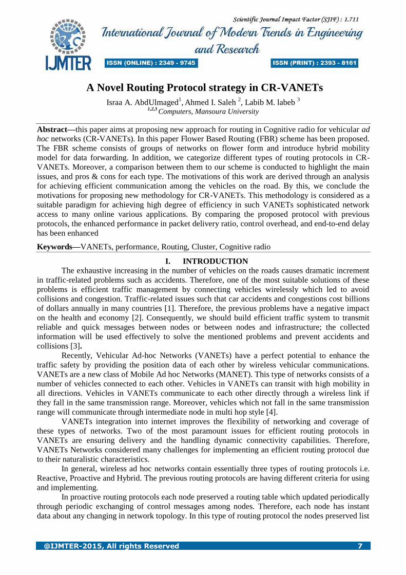
The proposal the network is called flower clusters which used Flower Based Routing (FBR)
protocol to route the packets between each other. It consist sofa group of network with flower shape,
each flower has two parts the first one is the flower core which controlled by Flower Center, the
second part is the number of flower leaves, each flower leave has Master Leaves (ML) that select
leaves members. The node within the same flower has the same ID and each flower connected with
another flowers by Neighbor Gateway (NG). Vehicles are grouped based on the location of flower center. Road side units act as static
flower center located at certain predefined places like junctions, traffic signals, hospitals, restaurants,
congested places, shopping malls, city exit points and toll gates. Vehicles that are within the range of
flower center become its members and information is shared between them in a full duplex manner.
Flower Leaves are formed around the flower center located at the road signals, street corners and
congested places. However, buses are chosen as master leaves based on speed, power and position,
as shown in Fig. 1
International Journal of Modern Trends in Engineering and Research (IJMTER) Volume 02, Issue 10, [October – 2015] ISSN (Online):2349–9745 ; ISSN (Print):2393-8161
@IJMTER-2015, All rights Reserved 10
Figure 1: Flower Clustering
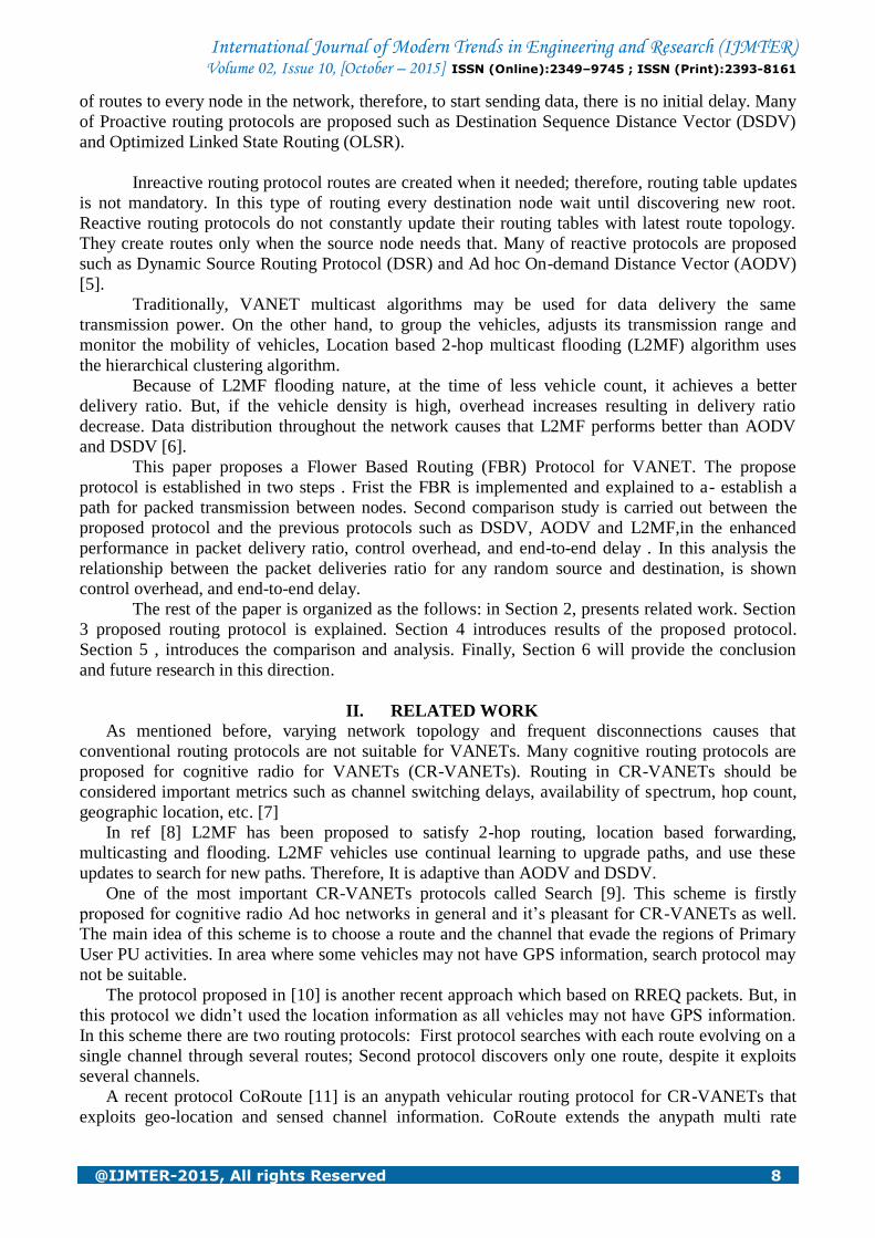
Flower leaves are consisting of three types of vehicle, master leaves, normal vehicle and gateway
vehicle, as shown in figure 2.
Figure 2: Flower Leaves

International Journal of Modern Trends in Engineering and Research (IJMTER) Volume 02, Issue 10, [October – 2015] ISSN (Online):2349–9745 ; ISSN (Print):2393-8161
@IJMTER-2015, All rights Reserved 11
After FC elect the ML. The ML will send messages contain the ID number to its members, if the
vehicle receives more than one message with different ID number it means that the Vehicle is
gateway. And then this gateway used to interconnect between two flowers.
If the vehicle receives more than one message with the same ID number from the same flower, the
gateway will neglect the message the ML can send to other ML via flower center.
3.1 Flower Formation Algorithm (F2M)
In this section, we will explain the formation of flower in the proposed algorithm is explained. The
construction of the flower is divided into two phases. The first phase is Flower Center Discovery
(FCD) which responsible for discovering all nodes existing in the flower center. In addition, FCD
needs to collect data for choosing the Leave Master (LMs). The second phase is Leave Master
Election (LME), in this phase some parameters will calculated to choose the ML. the flow chart of
figure (3) will show the F2M algorithm then the two phases is explained in details. In the fallowing
sections
3.1.1 Phase 1: Flower Center Discovery (FCD)
As mentioned before, the FCD is the process in which all nodes are discovered and data needed to
choose LMs are collected as follow:
1- The Flower Center (FC) will broadcast massage called Flower Formulation Massage (FFM)
to all nodes in the range. The message format is shown in the figure (4) .
Figure 4: FFM Message
2- When the previous message reach to certain node, the node will choose the level field such
that:
i- If there are old message received before and has the same time stamp, the node will
compare the level field and chooses the less level field and store it as a node level.
Then the level will increase by one and broadcast the message to all other nodes, and
send it as unicast to the FC to detect the path.
ii- If this message is the first one, in the current time stamp, the node will record the
level which contained in the message as its level. Then increase the level by one and
broadcast the message to all other nodes, and send it as unicast to the FC to detect the
path.
iii- If the node receives FFM message has less or equal time stamp less than the previous
time stamp, the node will discard the message.
iv- If the level equal n, the node will record its level as n. Then the node will send the
message unicast to the follower center according to the path recorded on the FFM
with additional information such as speed, power and position. The additional
information will help the FC to elect the LM.
Level
Path
Time Stamp Speed, Power and
Position

International Journal of Modern Trends in Engineering and Research (IJMTER) Volume 02, Issue 10, [October – 2015] ISSN (Online):2349–9745 ; ISSN (Print):2393-8161
@IJMTER-2015, All rights Reserved 12
Figure 3: Flow Chart of F2M
The example is shown in figure (5) shows how any certain node unicast the path to FC.
Figure 5: Unicast message to FC for FFM path
When the FFM message reach to the node, the node will separate the path included in FFM then add
it‟s ID.
International Journal of Modern Trends in Engineering and Research (IJMTER) Volume 02, Issue 10, [October – 2015] ISSN (Online):2349–9745 ; ISSN (Print):2393-8161
@IJMTER-2015, All rights Reserved 13
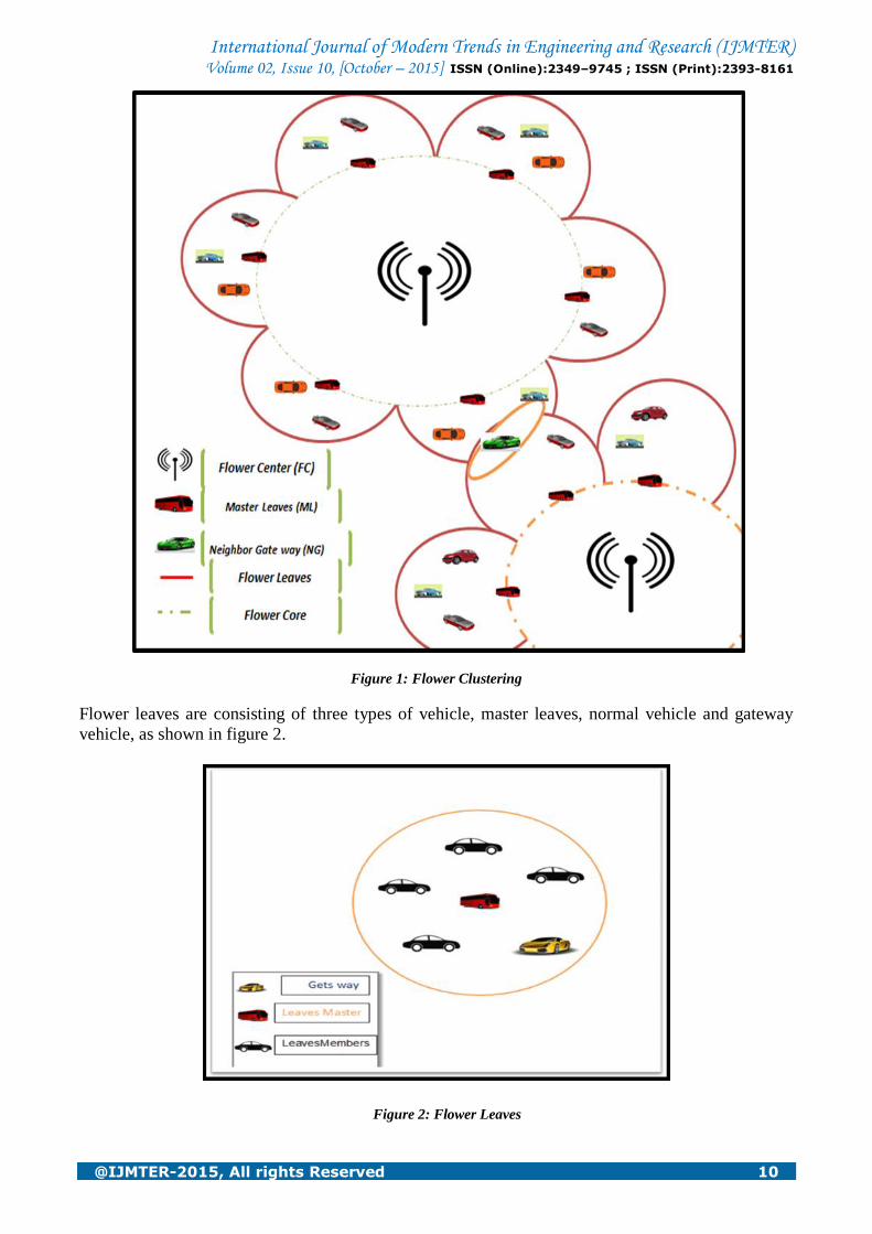
3.1.2 Phase 2: Master Leave Election (MLE)
The flower center is divided into group of sectors. In each sector, the nodes which located in level n
will be separated. If we suggested that M is the number of vehicle in round of flower center and we
need n of MLs. If n<=M then divide the flower center into group of sectors such that the number of
sectors are equal to 360/n. As in figure 6:
Figure 6: Sector formulation
The FC will elect the MLs according to the highest power and the lowest speed.
3.2 Flower Based Routing (FBR) Scheme
In the previous section the flower formulation is explained. In this section we will explain the
proposed routing protocol, FBR. Is explained flow chart will display the proposed algorithm. As
shown in the flow chart (figure 7), we suppose that the vehicle (A) need to send stream of data
packets to the vehicle (B), thus it needs to determine the path of the vehicle (B).Initially, and at any
sending process the Cognitive Radio (CR) network search for available channels around it. Therefore,
it selects the free channel which satisfies the quality of service (QoS) requirements. At this moment,
vehicle (A) sends request to Master Leaves (ML) to check whether the destinations in the same leave
and reply path to vehicle (A). Therefore vehicle (A) send data to vehicle (B).If the vehicle (B)is not
found in the same leaves, ML send request to Flower Center (FC) to ask about the path of vehicle
(B)and then FC search in its global table about the path of vehicle (B), if it was found, FC will check
the validation of this path, if the path valid, it send acknowledge (ACK) to ML. Therefore, ML will
send ACK to vehicle (A), accordingly, vehicle (A) send data to vehicle (B).If FC doesn't found the
path in its table, it will send reply message "path is not found ". Then, ML sends request path of
vehicle (B) to another neighbor Master Leaves (NML) using gateway node. If NML found the path
in local leaves, it will send ACK to ML. therefore, ML send reply path to vehicle (A). Then vehicle
(A) will send data to vehicle (B). IF NML doesn't found the path in local leaves, it will send reply
"path doesn't fond" to ML .Therefore; ML informs the FC that the path is not found. Accordingly,
FC will send flooding request and wait for threshold time. If FC found vehicle (B), it will reply path
to ML. then ML reply the path to vehicle (A), therefore, vehicle (A) send data to vehicle (B). If FC
doesn't found vehicle (B), it will reply vehicle (B) is not found..

International Journal of Modern Trends in Engineering and Research (IJMTER) Volume 02, Issue 10, [October – 2015] ISSN (Online):2349–9745 ; ISSN (Print):2393-8161
@IJMTER-2015, All rights Reserved 14
Figure 7: Flow Chart of FBR

International Journal of Modern Trends in Engineering and Research (IJMTER) Volume 02, Issue 10, [October – 2015] ISSN (Online):2349–9745 ; ISSN (Print):2393-8161
@IJMTER-2015, All rights Reserved 15
3.3 FBR Routing Cases
FBR as a routing algorithm can be broadly divided into two cases, the first case is inter
flower Routing and the second one is intra flower routing.
3.3.1 Case 1: Inter flower routing
Inter flower Routing is meaning that routing within the flower itself and it divided into two situations:
i. When the source node (A) needs to send packet to certain destination node (B) in the same
leave. The source will ask master leave to check whether the destination node is within
the local leaves or not. If the destination node is present within the leaves then the master
leaves send the reply packet with its ID embedded in the packet to the source. Now, the
source node forwards all the data packets required to be sent to the destination node after
getting the path from the master leave. As in figure 8.
Figure 8: two nodes in the same leave
ii. When the source need to send packet to certain destination in different leave in the same
flower. In this situation the master leaves send request to the flower center to check in its
table about destination path. The flower center reply with packet contains its ID
embedded in the packet. Now, the source node forwards all the data packets required to
be sent to the destination node. As in the figure 9.
Figure 9: two nodes in different leaves

International Journal of Modern Trends in Engineering and Research (IJMTER) Volume 02, Issue 10, [October – 2015] ISSN (Online):2349–9745 ; ISSN (Print):2393-8161
@IJMTER-2015, All rights Reserved 16
3.3.2 Intra flower routing
Intra flower Routing is meaning that routing out the flower and it divided into two situations:
iii. When the source need to send packet to certain destination in different flower. In this
situation the master leaves doesn‟t have information about destination, therefore it sends
request to other master leaves by gateway node. As in figure 10.
Figure 10: two nodes in different flower
iv. When the source need to send packet to certain destination in neighbor leave in different
flower. In this case the destination node doesn‟t exist in the neighbor leave, therefore the
flower center send flooding request to other flower leaves and wait for threshold time.
4.4 Route Maintenance
Route maintenance is the operation of following up the vehicles movements and modifications of
paths continually in the period between two flowers construction. As shown in figure (11).
Figure 11: route maintenance
The movements of vehicles divided into two cases:
3.4.1 Case 1: if the vehicle moves inside the flower, the movement of the vehicle will be one of the
following:
1. Core To Leave Same flower (CTLS)
2. Leaves To Leaves Same flower (LTLS)

International Journal of Modern Trends in Engineering and Research (IJMTER) Volume 02, Issue 10, [October – 2015] ISSN (Online):2349–9745 ; ISSN (Print):2393-8161
@IJMTER-2015, All rights Reserved 17
3. Leaves To Leaves Different flower (LTLD)
4. Leaves To Core Same flower (LTCS)
Now, we will explain in details the cases mentioned before.
For any movements of vehicles, the position ID will be stored in the position ID field which changed
its value after handshaking operation. The position ID consists of flower ID and Identity number as
in figure( 12) .
Figure 12: Position ID
The flower ID is the flower number, if this number changed, that is meaning that the vehicle moves from the current flower to the other one.
The identity number is the core and leaves number. We have to know that the identity number
is always zero for core. If this number changed, that is meaning that the vehicle moves from
leaves to core or from core to leaves or from leaves to another one.
3.4.1.1 Core To Leave Same flower (CTLS)
In this case, the vehicle moves from core to leaves in the same flower and also it meaning that the
identity number changed from 0 to the leaves number. Therefore, the Master Leave (ML) will make
record for this vehicle and inform the Flower Center (FC) that this vehicle joined it. Consequently,
the FC will remove this vehicle from its entries as in figure (13).
Figure 13: Core To Leave Same flower (CTLS)
Flower ID
Identity number
Position ID
International Journal of Modern Trends in Engineering and Research (IJMTER) Volume 02, Issue 10, [October – 2015] ISSN (Online):2349–9745 ; ISSN (Print):2393-8161
@IJMTER-2015, All rights Reserved 18
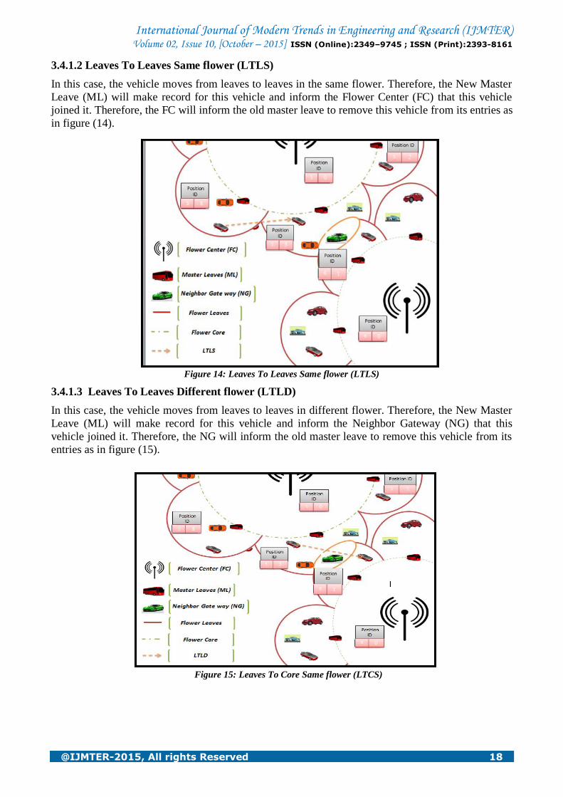
3.4.1.2 Leaves To Leaves Same flower (LTLS)
In this case, the vehicle moves from leaves to leaves in the same flower. Therefore, the New Master
Leave (ML) will make record for this vehicle and inform the Flower Center (FC) that this vehicle
joined it. Therefore, the FC will inform the old master leave to remove this vehicle from its entries as
in figure (14).
Figure 14: Leaves To Leaves Same flower (LTLS)
3.4.1.3 Leaves To Leaves Different flower (LTLD)
In this case, the vehicle moves from leaves to leaves in different flower. Therefore, the New Master
Leave (ML) will make record for this vehicle and inform the Neighbor Gateway (NG) that this
vehicle joined it. Therefore, the NG will inform the old master leave to remove this vehicle from its
entries as in figure (15).
Figure 15: Leaves To Core Same flower (LTCS)
International Journal of Modern Trends in Engineering and Research (IJMTER) Volume 02, Issue 10, [October – 2015] ISSN (Online):2349–9745 ; ISSN (Print):2393-8161
@IJMTER-2015, All rights Reserved 19
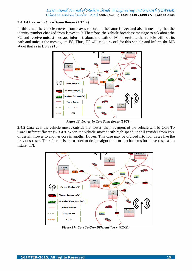
3.4.1.4 Leaves to Core Same flower (LTCS)
In this case, the vehicle moves from leaves to core in the same flower and also it meaning that the
identity number changed from leaves to 0. Therefore, the vehicle broadcast message to ask about the
FC and receive unicast message inform it about the path of FC. Therefore, the vehicle will put its
path and unicast the message to FC. Thus, FC will make record for this vehicle and inform the ML
about that as in figure (16).
Figure 16: Leaves To Core Same flower (LTCS)
3.4.2 Case 2: if the vehicle moves outside the flower, the movement of the vehicle will be Core To
Core Different flower (CTCD). When the vehicle moves with high speed, it will transfer from core
of certain flower to another core in another flower. This case may be divided into four cases like the
previous cases. Therefore, it is not needed to design algorithms or mechanisms for those cases as in
figure (17).
Figure 17: Core To Core Different flower (CTCD).
International Journal of Modern Trends in Engineering and Research (IJMTER) Volume 02, Issue 10, [October – 2015] ISSN (Online):2349–9745 ; ISSN (Print):2393-8161
@IJMTER-2015, All rights Reserved 20
IV. IMPLEMENTATION OF THE FBR
The efficiency of FBR algorithm is evaluated in a number of simulation tests. Ns-2 simulator is
used for the comparison of the performance of FBR, AODV, DSDV and L2MF. Ns-2 trace files are
analyzed using trace graph [13]. Simulation considers, number of vehicles ranging from 50 to 500
placed randomly in an area of 2500m X 2500m. Each experiment is run for 2000 seconds. Data
traffic is generated by 25 constant bit rate (CBR) sources. The sources send one 512-byte packet per
second. Each CBR source starts sending at a random time between 0 and 180 seconds after the start
of simulation, and keeps sending till the end. At the physical layer a two-ray signal propagation
model is used.
The radio propagation range of the nodes is 250m. For different experiments in this setting, the
mobility patterns of the nodes were varied. The tests with random waypoint mobility model were
done to know impact of the variations in vehicle speed and the pause time. In Group Mobility Model,
analysis is based on its location and speed. The simulation parameters for FBR are shown in Table 1.
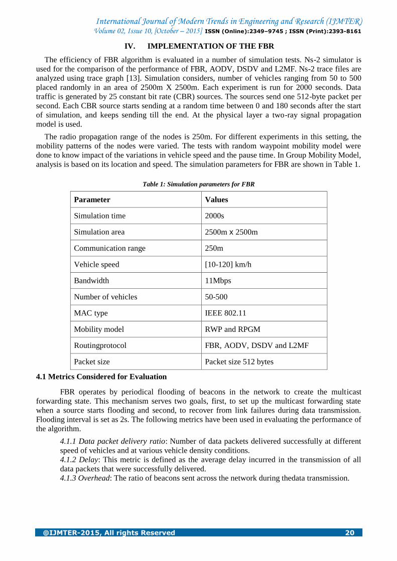
Table 1: Simulation parameters for FBR
Parameter Values
Simulation time 2000s
Simulation area 2500m x 2500m
Communication range 250m
Vehicle speed [10-120] km/h
Bandwidth 11Mbps
Number of vehicles 50-500
MAC type IEEE 802.11
Mobility model RWP and RPGM
Routingprotocol FBR, AODV, DSDV and L2MF
Packet size Packet size 512 bytes
4.1 Metrics Considered for Evaluation
FBR operates by periodical flooding of beacons in the network to create the multicast
forwarding state. This mechanism serves two goals, first, to set up the multicast forwarding state
when a source starts flooding and second, to recover from link failures during data transmission.
Flooding interval is set as 2s. The following metrics have been used in evaluating the performance of
the algorithm.
4.1.1 Data packet delivery ratio: Number of data packets delivered successfully at different
speed of vehicles and at various vehicle density conditions.
4.1.2 Delay: This metric is defined as the average delay incurred in the transmission of all
data packets that were successfully delivered.
4.1.3 Overhead: The ratio of beacons sent across the network during thedata transmission.

International Journal of Modern Trends in Engineering and Research (IJMTER) Volume 02, Issue 10, [October – 2015] ISSN (Online):2349–9745 ; ISSN (Print):2393-8161
@IJMTER-2015, All rights Reserved 21
V. RESULTS & ANALYSIS
We measure performance in different cases and conditions as follows:
5.1 Impact of Vehicle Density
Density is defined as the number of vehicles per unit length of the roadway. Data packet
delivery ratio is considered as the metric for measuring the performance at various vehicle densities.
Figure 11 shows the impact of vehicle density on data packet delivery ratio. The FBR achieves a
better delivery ratio at the time of less vehicle count because of its flooding nature. Flooding is an
important communication primitive in mobile ad-hoc networks and also serves as a building block
for more complex protocols such as routing protocols. Flooding is well controlled and not used
repeatedly as done in L2MF which may cause traffic congestion. In high vehicle density, overhead
increases resulting in delivery ratio decrease. Compared to L2MF, AODV and DSDV, FBR performs
better because of data distribution throughout the network. AODV can perform a local repair to the
source node using routing tables.
Figure 11: Data packet delivery ratio at various vehicle densities
Figure 12 shows the delay of transmission during different vehicle density situations. At low-
density conditions, FBR reduces delay. In high density conditions, node dispersion increases delay.
Figure 12: Delays of transmission at various vehicle densities
International Journal of Modern Trends in Engineering and Research (IJMTER) Volume 02, Issue 10, [October – 2015] ISSN (Online):2349–9745 ; ISSN (Print):2393-8161
@IJMTER-2015, All rights Reserved 22
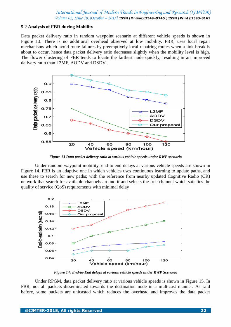
5.2 Analysis of FBR during Mobility
Data packet delivery ratio in random waypoint scenario at different vehicle speeds is shown in
Figure 13. There is no additional overhead observed at low mobility. FBR, uses local repair
mechanisms which avoid route failures by preemptively local repairing routes when a link break is
about to occur, hence data packet delivery ratio decreases slightly when the mobility level is high.
The flower clustering of FBR tends to locate the farthest node quickly, resulting in an improved
delivery ratio than L2MF, AODV and DSDV .
Figure 13 Data packet delivery ratio at various vehicle speeds under RWP scenario
Under random waypoint mobility, end-to-end delays at various vehicle speeds are shown in
Figure 14. FBR is an adaptive one in which vehicles uses continuous learning to update paths, and
use these to search for new paths; with the reference from nearby updated Cognitive Radio (CR)
network that search for available channels around it and selects the free channel which satisfies the
quality of service (QoS) requirements with minimal delay
Figure 14: End-to-End delays at various vehicle speeds under RWP Scenario
Under RPGM, data packet delivery ratio at various vehicle speeds is shown in Figure 15. In
FBR, not all packets disseminated towards the destination node in a multicast manner. As said
before, some packets are unicasted which reduces the overhead and improves the data packet
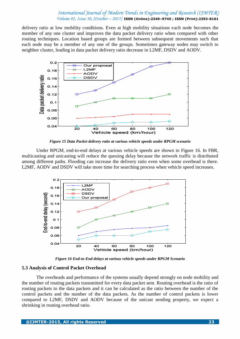
International Journal of Modern Trends in Engineering and Research (IJMTER) Volume 02, Issue 10, [October – 2015] ISSN (Online):2349–9745 ; ISSN (Print):2393-8161
@IJMTER-2015, All rights Reserved 23
delivery ratio at low mobility conditions. Even at high mobility situations each node becomes the
member of any one cluster and improves the data packet delivery ratio when compared with other
routing techniques. Location based groups are formed between subsequent movements such that
each node may be a member of any one of the groups. Sometimes gateway nodes may switch to
neighbor cluster, leading in data packet delivery ratio decrease in L2MF, DSDV and AODV.
Figure 15 Data Packet delivery ratio at various vehicle speeds under RPGM scenario
Under RPGM, end-to-end delays at various vehicle speeds are shown in Figure 16. In FBR,
multicasting and unicasting will reduce the queuing delay because the network traffic is distributed
among different paths. Flooding can increase the delivery ratio even when some overhead is there.
L2MF, AODV and DSDV will take more time for searching process when vehicle speed increases.
Figure 16 End-to-End delays at various vehicle speeds under RPGM Scenario
5.3 Analysis of Control Packet Overhead
The overheads and performance of the systems usually depend strongly on node mobility and
the number of routing packets transmitted for every data packet sent. Routing overhead is the ratio of
routing packets to the data packets and it can be calculated as the ratio between the number of the
control packets and the number of the data packets. As the number of control packets is lower
compared to L2MF, DSDV and AODV because of the unicast sending property, we expect a
shrinking in routing overhead ratio.

International Journal of Modern Trends in Engineering and Research (IJMTER) Volume 02, Issue 10, [October – 2015] ISSN (Online):2349–9745 ; ISSN (Print):2393-8161
@IJMTER-2015, All rights Reserved 24
Figure 17 shows the routing overheads at various vehicle speeds at random waypoint
mobility conditions. At random waypoint, high mobility scenario, FBR does not allow rerouting
operation. In DSDV, routing table updates take more time. In AODV, the dynamic nature does not
yield quick results. In L2MF, control packet overhead increases when mobility increases due to
repetitive flooding and data broadcasting.
Figure 17 Routing overheads at various vehicle speeds under RWP Scenario
Figure 18 shows the routing overhead at RPGM scenario. In FBR, the overhead at high
mobility conditions, because of group mobility and their corresponding faraway transaction,
increases whenever vehicle speed increases.
Figure 18 Routing overheads at various vehicle speeds under RPGM Scenario
6.4 Analysis of the Number of Successful Delivery of Packets
Figure 19 shows the number of packets that are delivered successfully during data transmission.

International Journal of Modern Trends in Engineering and Research (IJMTER) Volume 02, Issue 10, [October – 2015] ISSN (Online):2349–9745 ; ISSN (Print):2393-8161
@IJMTER-2015, All rights Reserved 25
Figure 19 Number of successfully delivered packets
In FBR, packets are distributed only towards the destination direction based on the neighbor
table entries. FBR relies on routing table entries maintained in both flower center and master leaves,
the number of packets reached destination successfully is more with minimal loss compared to
L2MF, AODV and DSDV.
Flooding, multicasting and data broadcasting are used carefully in FBR unlike other
algorithms. Unicasting sending aids in minimizing traffic jam especially in case of high vehicle
density. Unicasting in addition to distributed centralization and well arranging of vehicles in flower
clustering has shown to enhance data packet delivery ratio and decrease delay and overhead.
VI. CONCLUSIONS
In this thesis, a new method has been proposed as a routing algorithm in VANETs named
FBR. FBR is considered to be a suitable paradigm for achieving high degree of efficiency in such
VANETs sophisticated network access to many online various services and applications.
FBR was shown to improve upon the existing state-of-the-art methods for routing protocols
in VANETs. We described the concept of FBR and its cluster construction idea and different packet
routing cases.
By comparing the proposed protocol with previous protocols such that L2MF, AODV and
DSDV, the enhanced performance in packet delivery ratio, control overhead, and end-to-end delay
has been improved.
Many years of effort will be required to refine system designs and propose other
methodologies, to satisfy the needed safety and reliability capabilities.
REFERENCES
[1] Jianqi Liu, JiafuWan, Qinruo Wang, Pan Deng, Keliang Zhou, YupengQiao, “A survey on position-based routing
for vehicular ad hoc networks”, © Springer Science + Business Media, New York, 2015
[2] M. Seredynski, P. Bouvry, A survey of vehicular-based cooperative traffic infor-mation systems, in: 14th
International IEEE Conference on Intelligent Trans-portation Systems (ITSC), pp.163–168, 2011.
[3] Wan, J., Yan, H., Suo, H., & Li, F. (2011). Advances in cyberphysical systems research.KSII Transactions on
Internet and InformationSystems, 5(11), 1891–1908.
[4] B.S.C. Lochert, J. Rybicki, M. Mauve, Scalable data dissemination for inter-vehicle-communication: aggregation
versus peer-to-peer, Inf. Technol. J. 50 237–242 , (2008).
[5] YASHI RAJVANSHI, SEEMA RAHUL, SANJAY KUMAR MAURYA, SANDIP VIJAY, “Comparative study of
different Parameters of MANET Routing Protocol for different Buffer Size”, Conference on Advances in
Communication and Control Systems 2013 (CAC2S 2013).
International Journal of Modern Trends in Engineering and Research (IJMTER) Volume 02, Issue 10, [October – 2015] ISSN (Online):2349–9745 ; ISSN (Print):2393-8161
@IJMTER-2015, All rights Reserved 26
[6] D. Rajinigirinath, S. Selvan, “Investigations on vehicles guided by updated road and maps”, PRZEGLĄD
ELEKTROTECHNICZNY, ISSN 0033-2097, R. 89 NR 9/2013.
[7] Kamal Deep Singh, PriyankaRawat, and Jean-Marie Bonnin, “Cognitive radio for vehicular ad hoc networks(CR-
VANETs): approaches and challenges”, EURASIP Journal on Wireless Communications and Networking, 2014.
[8] D. RajiniGirinath, S. Selvan, “A novel hierarchical model for vehicular traffic regulation”, TelecommunSyst (2013)
52:2101–2114, Springer Science+Business Media, LLC 2011.
[9] KR Chowdhury, MD Felice, SEARCH: a routing protocol for mobile cognitive radio ad-hoc networks.
Comput.Common. 32(18), 1983–1997 (2009)
[10] AS Cacciapuoti, M Caleffi, L Paura, Reactive routing for mobile cognitive radio ad hoc networks. Ad Hoc
Networks. 10(5), 803–815 (2012)
[11] W Kim, M Gerla, SY Oh, K Lee, A Kassler, CoRoute: a new cognitive anypath vehicular routing protocol.
Wireless Comm. Mobile Comput.11(12), 1588–1602 (2011)
[12] R Laufer, H Dubois-Ferriere, L Kleinrock, Multirateanypath routing in wireless mesh networks, in IEEE
INFOCOM (Rio de Janeiro, 19–25April 2009), pp. 37–45 , 2009
[13] Jaroslaw Malek , „Trace graph‟, http://www.angelfire.com/al4/esorkor/,2002.
