a novel robust adaptive control algorithm and application ... · control scheme, the inverter...
TRANSCRIPT

SERBIAN JOURNAL OF ELECTRICAL ENGINEERING Vol. 7, No. 1, May 2010, 21-40
21
A Novel Robust Adaptive Control Algorithm and Application to DTC-SVM of AC Drives
Sebti Belkacem1, Farid Naceri1, Rachid Abdessemed2
Abstract: In this paper a new robust adaptive control algorithm for AC machine is presented. The main feature of this algorithm is that minimum synthesis is required to implement the strategy. The MCS algorithm is a signifiant development of MRAC and is similary based on the hyperstability theory of Popov. The hyperstability theory guarantees the global asymptotic stability of the error vector (i.e. the difference between the reference model and system states). Finally, a new approach has been successfully implemented to DTC-SVM. Discussion on theoretical aspects, such as, selection of a reference model, stability analysis, gain adaptive and steady state error are included. Results of simulations are also presented.
Keywords: Minimum Controller Synthesis (MCS), Robust Approach, AC Machine, DTC-SVM, Lyapunov Function.
1 Introduction
The industrial application areas of the direct torque control (DTC) scheme have been increased due to several factors such as quick torque response and robustness against the motor parameter variations [1, 2]. The conventional DTC algorithm using the hysteresis based voltage switching method has relative merits of simple structure and easy implementation.
The performance of such a scheme depends on the error band set between the desired and measured torque and stator flux values. In addition, in this control scheme, the inverter switching frequency is changed according to the hysteresis bandwidth of flux and torque controllers and the variation of speed and motor parameters. Superior motor performance is achieved by narrower hysteresis bands especially in the high speed region.
However, these bands cannot be set too small for the protection of the inverter power switching devices. As a result, this approach will not be suitable for high power drives such as those used in tractions, as they require good torque control performance at considerably lower frequency [3-5]. For such
1Department of Electrical Engineering, University of Batna, 05000, Algeria; E-mail: [email protected] 2LEB, Department of Electrical Engineering, University of Batna, 05000, Algeria
UDK: 621.313.3:517.938

S. Belkacem, F. Naceri, R. Abdessemed
22
high power industrial applications, if in the DTC, the hysteresis bands of the controllers become relatively wide, with the low inverter switching frequency, the resulting motor torque pulsations are high up to an undesired level.
To overcome the above problems, so far a few researchers have presented, the DTC scheme using the space vector modulation (SVM) techniques [6-10]. In [7] a control method has been discussed that allows constant switching frequency operation and uses two PI controller in order to generate the inverter reference voltage in the IM stator flux reference frame. In that control scheme, a PI speed controller is also used to obtain the torque reference signal.
The control scheme in [7] is not robust to parameters uncertainty, especially to the stator resistance variations. In addition, it requires an on-line transformation the machine variables from a stationary reference frame to the stator flux reference frame and vice-versa.
To control the speed of an induction motor driven by the DTC-SVM. The Proportional-Integral controller is always the preferred choice as highlighted by [11]. This is because the implementation of the PI controller requires minimal information about the motor, where the controller gains are tuning until a satisfactory response is obtained [12,13].
As, the induction motor is naturally a non-linear system and is subjected to parameter variations, external disturbances, and non-linear loads, PI controller may not give satisfactory performance when subjected to these conditions as shown by [14,15]. This has prompted the development of a more robust adaptive controller for AC motor drives. Much effort has been devoted to developing robust adaptive control for AC motor drives. As consequence, a number of robust adaptive control methods have been developed and good robustness results have been obtained. Lorenz and Lawson have proposed a MRAC as a solution to the problem of on-line tuning of the field oriented induction machine drive [16]. By using a Proportional-Integral controller in a feedback to modulate the slip constant, the error between the desired torque and the calculated torque is null and the system actively pursues field oriented. Like the other methods, machine inductance ratios must be known or estimated. However MRAC, requires the knowledge of the nominal plant characteristics and FOC requires that the motor parameters to be known in its implementation [17, 18]. Hence, laborious commissioning process has to be carried out prior to running the motor. [19] suggested a simpler approach by replacing the MRAC with the Minimum Controller Synthesis (MCS) algorithm [20-23]. MCS is a significant extension to model reference adaptive control (MRAC). In a similar manner to MRAC, the aim of MCS is to achieve excellent closed-loop control despite the presence of system parameter variations, external disturbances, dynamic coupling within the system and system non-linearity.
A Novel Robust Adaptive Control Algorithm and Application to DTC-SVM...
23
However, unlike MRAC, MCS requires no system model identification (apart from the general structure of a state-space equation) or linear controller synthesis.
The objective of this paper, first to solve the problems of torque ripple and inconstant switch frequency of inverter in the conventional direct torque control, a new DTC-SVM method for a speed control of AC motor drive is proposed, second, to control the speed of AC motor driven by DTC-SVM using MCS algorithm. In order to preserve the system robustness with respect to load disturbance variations and uncertainties. Induction motor drive simulation model with DTC-SVM is created and studied using MATLAB. Simulation results demonstrate the feasibility and validity of the proposed DTC system by effectively accelerating system response, reducing torque and flux ripple and a very satisfactory performance has been achieved.
2 DTC Space Vector Modulation (DTC-SVM)
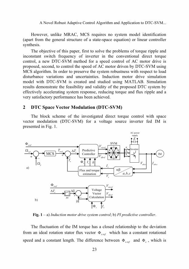
The block scheme of the investigated direct torque control with space vector modulation (DTC-SVM) for a voltage source inverter fed IM is presented in Fig. 1.
Fig. 1 – a) Induction motor drive system control; b) PI predictive controller.
The fluctuation of the IM torque has a closed relationship to the deviation from an ideal rotation stator flux vector Φs ref which has a constant rotational
speed and a constant length. The difference between Φs ref and Φs , which is

S. Belkacem, F. Naceri, R. Abdessemed
24
generated in three-phase PWM inverter, cause torque pulsation. In this case, the tip of the vector goes along a polygon close to a circle as shown in Fig. 2. The relationship between torque pulsation ΔΤe and the deviation of Φs from Φs ref has been deduced as:
| || |
e ss
eref sref
Tk k
T δ
Δ ΔΦ= + Δδ
Φ, (1)
where Τe ref is the steady state torque ΔΦs and Δδ are respectively the
deviations from Φs and δ which are defined by:
ΔΦ Φ Φs s ref s = − , (2)
Δ Φ Φs ref sδ = ∠ −∠ , (3)
where kδ and sk are the constants derived from the IM specifications.
The torque ripple is actually caused by ΔΦs and Δδ , and the influence of the ΔΦs is considerably smaller than that of Δδ . As a consequence the torque ripple can be almost removed if Δδ is kept close to zero.
Equation (1) shows that the relation between torque error and increment angle Δδ is linear. Therefore a PI predictive controller, which generates the load angle changes to minimize the instantaneous error between reference and actual torque, is applied.
From the internal structure of the predictive torque and stator flux controller shown in Fig. 1b, one can notice that the torque error, ΔΤe and
reference stator flux amplitude, Φs ref are delivered to a predictive controller
which in its output gives the deviation of reference stator flux angle, Δδ . From this figure the α , β axes components of the stator reference voltage
s refV , are calculated as:
( )cos cos
s ref
s refs ref
s ss
V R ITα α
Φ δ + Δδ Φ= +
− δ, (4)
( )sin sin s ref
s refs ref
s ss
V R ITβ β
Φ δ + Δδ Φ= +
− δ, (5)
A Novel Robust Adaptive Control Algorithm and Application to DTC-SVM...
25
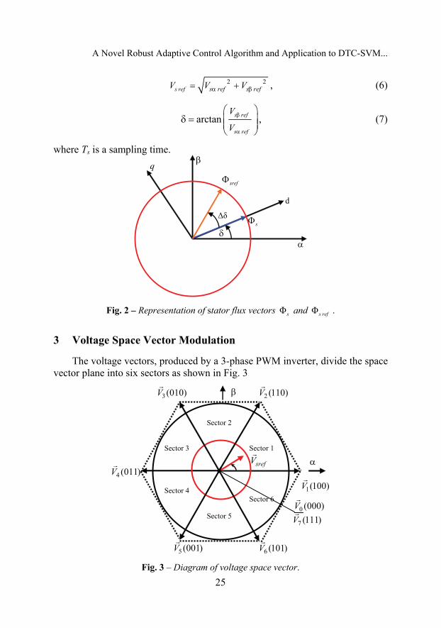
2 2s ref s ref s refV V Vα β= + , (6)
arctan s ref
s ref
V
Vβ
α
⎛ ⎞δ = ⎜ ⎟⎜ ⎟
⎝ ⎠, (7)
where Ts is a sampling time.
Fig. 2 – Representation of stator flux vectors Φs and Φs ref .
3 Voltage Space Vector Modulation
The voltage vectors, produced by a 3-phase PWM inverter, divide the space vector plane into six sectors as shown in Fig. 3
Fig. 3 – Diagram of voltage space vector.

S. Belkacem, F. Naceri, R. Abdessemed
26
In every sector, the arbitrary voltage vector is synthesized by basic space voltage vector of the two side of sector and one zero vector. For example, in the first sector, s refV is a synthesized voltage, space vector and its equation is given by: 0 0 1 1 2 2s ref sV T V T V T V T= + + , (8)
0 1 2sT T T T= + + , (9)
where, 0T , 1T , 2T are the work times of basic space voltage vector 0V , 1V , 2V respectively.
Fig. 4 – Projection of the reference voltage vector.
The determination of times 1T and 2T is given by simple projections:
( )1 6 22
ss ref s ref
TT V V
E β α= − , (10)
2 2 ss refE
TT V β= . (11)
The rest of the period spent in applying the null-vector. For every sector, commutation period is calculated. The amount of times of vector application can all be related to the following variables:
2ss ref
TX V
E β= , (12)

A Novel Robust Adaptive Control Algorithm and Application to DTC-SVM...
27
2 62 2
ss ref s ref
TY V V
E β α
⎛ ⎞= +⎜ ⎟⎜ ⎟
⎝ ⎠, (13)
2 62 2
ss ref s ref
TZ V V
E β α
⎛ ⎞= −⎜ ⎟⎜ ⎟
⎝ ⎠. (14)
Table 1 Application durations of the sector boundary vectors are tabulated as:
SECTOR 1 2 3 4 5 6
T1 Z Y –Z –X X –Y
T2 Y –X X Z –Y –Z
The goal of this step is to compute the three necessary duty cycles as:
1 2
2s
aonT T T
T− −
= , (15)
1aonbonT T T= + , (16)
2con bonT T T= + . (17)
The last step is to assign the right duty cycle ( xonT ) to the right motor phase according to the sector.
Table 2 Assigned duty cycles to the PWM outputs.
SECTOR 1 2 3 4 5 6
Sa Tbon Taon Taon Tcon Tbon Tcon
Sb Taon Tcon Tbon Tbon Tcon Taon
Sc Tcon Tbon Tcon Taon Taon Tbon
4 Robustness of the MCS Algorithm in the Presence of External Disturbances
Consider a plant described by the following state space equation: ( ) ( ) ( ) ( ) ( , )t t t t x t= + +x A x Bu d , (18)

S. Belkacem, F. Naceri, R. Abdessemed
28
where: ( ) n nt R ×∈A and 1nR ×∈B ,
d: the external disturbances,
[ ]T1 2 n= x , x ,..., xx , 1nR ×∈x .
Similarly, the reference model is defined by the following state equation: ( ) ( ) ( )m m m mt t t r= +x A x B , (19)
where n nm R ×∈A and 1n
m R ×∈B .
The disturbance term d that represents the effects of external disturbances, and/or plant non-linearity, can be written as: ( )t r= δd A , (20)
where [ ]( ) 0,..., 0 ( ) Tt a tδ = δA and 1( ) nt R ×δ ∈A .
The term ( )a tδ is a bounded and time varying coefficient depending on ( , )x td and ( )r t . If ( )tδA is slowly varying, i.e constant during the adaptation
process, then the error ex is globally asymptotically stable. If d is bounded and rapidly varying, then the global asymptotic stability of ex is no longer ensured and d is then considered as an external input to the system defined by: T T
e m e= − − −x A x bW Φ bW γ d , (21)
1T
eb= α.Φ b Px W , (22)
1T
eb= βγ b Px W . (23)
Note that if 2L∈d , then the system defined by (21) to (23) is an asymptotically hyperstable system.
4.1 Derivation of the upper bound of convergence of the error ex
Consider the Lyapunov function:
1
1( , ) T Te e eV
b= +
αx Φ x Px Φ Φ . (24)
By evaluating the time derivative of V along the trajectories of (21) and using relations (22) and (23) we obtain:
1
.2 2T T T T T
e e ee eV b= − − β −x Qx x Pbb Px W W x Pbd . (25)

A Novel Robust Adaptive Control Algorithm and Application to DTC-SVM...
29
If .
V is negative outside a closed region including the origin of the ex space, then all the solutions ex of (21) will be within this region. In this case,
observing that the matrix TPbb P is positive semidefinite and using general properties of norms, we obtain from (25):
2maxmin
.( , ) ( ) 2 ( )e e eV ≤ −λ + λx Φ Q x x P d . (26)
From (26), we observe that if max
min
2 ( )( )e
λ≥
λ
P dx
Q, then
.V is negative. We
conclude that ex enters the hypersphere region Ω defined by:
max max
min
2 ( )/
( )n
e eR⎧ ⎫λ⎪ ⎪Ω = ∈ ≤⎨ ⎬λ⎪ ⎪⎩ ⎭
P dx x
Q,
where maxd denotes the maximum values of d . We notice that Ω depends on
the magnitude of the disturbance as well as on the values of P and Q, which are related by the reference model values, (see (23)).
5 Application to an AC Machine
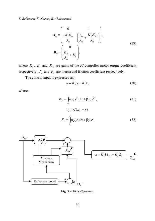
The above robust approach to MCS algorithm is applied to an AC machine. The proposed configuration Fig. 5 has two states speed and acceleration (see equation (28)) for an AC drive and has two differences compared to the standard MCS algorithm. The first is the output error expressed by: 1 1me x x= − . (27)
The second is the model and plant accelerations, which are not required, and hence only one feedback loop and adaptive gain is used.
The second order reference model, consisting of a closed-loop PI controller and the drive’s dynamic equations of motion, was chosen in the state variable form given as: m m m m r= +x A x B , (28)
where:
, rm ref
m
ra
⎛ ⎞Ω= = Ω⎜ ⎟⎝ ⎠
x ,
S. Belkacem, F. Naceri, R. Abdessemed
30
0 1,
0 ,
p mm i m m
m m m
m mi
m
K KK K FJ J J
KK
J
⎛ ⎞⎜ ⎟
= ⎛ ⎞−⎜ ⎟+⎜ ⎟⎜ ⎟⎝ ⎠⎝ ⎠⎛ ⎞⎜ ⎟= ⎜ ⎟+⎜ ⎟⎝ ⎠
A
B
(29)
where pK , iK and mK are gains of the PI controller motor torque coefficient
respectively. mJ and mF are inertia and friction coefficient respectively.
The control input is expressed as: f ru K x K r= + , (30)
where:
0
dt
T Tf e eK y x y x= α τ + β∫ , (31)
( )e my C x x= − ,
0
dt
r e eK y r y r= α τ + β∫ . (32)
Fig. 5 – MCS Algorithm.

A Novel Robust Adaptive Control Algorithm and Application to DTC-SVM...
31
5.1 Stability analysis of adaptive system In all stability based MRAC methods, the objective is to derive a control
input u that ensures the global asymptotic stability of the error ex for all initial conditions of ex , r, x and u. The error dynamic model can be defined as:
e m e e e= − −x A x B W d . (33)
A step-by-step procedure for the design of MRAC systems is given by Landau, as summarised in the following: • Transform the MRAC system into an equivalent standard feedback system
composed of two blocks as in Fig. 6.
Fig. 6 – Closed –loop equivalent system. • Find the solutions for the part of the adaptation laws that appear in the
feedback path on the equivalent system such that the Popov’s integral inequality is satisfied.
• Find the solutions for the remaining part of the adaptation law, which appear in the feedforward path that the feedforward path is represented by a positive (or strictly positive) real transfer matrix. This ensures the global stability (or global asymptotic stability) of the system.
Following the design steps, equation (33) is split into two blocks: a) a linear time invariant feedforward block b) a non linear time varying feedback block. The error dynamic model for the proposed system can be defined as:
e m e e e= − −x A x B W d , (34)
where:
– [ ]( ) ( ) ( ) ( )e m mfK t t K t r tr⎡ ⎤= + − + −⎣ ⎦W B A A x B B ,
– d is an external input to the system (disturbances). If the following conditions are satisfied:
S. Belkacem, F. Naceri, R. Abdessemed
32
[ ]1
0
21 1 0( ) ( ) ( ) for all
tTe r m
t
t K t r t c t t− ≥ − ≥∫ y B B , (35)
1
0
22( ) ( ) ( )
tTe f m
t
t K t x t c⎡ ⎤+ − ≥⎣ ⎦∫ y B A A , (36)
where 1c and 2c are constant independent of 1t and
e e=y Cx . (37)
The feed forward transfer function matrix
[ ]-1m es −C I A B (38)
is strictly positive real. By using the Kalman-Yacubovitch, the transfer function matrix [ ]-1
m es −C I A B is strictly positive real if there exists a symmetric positive definite matrix Q and a symmetric positive matrix P so that :
,
,
Tm m
n
+ = −= =
A P PA QC I P P
, (39)
where P is the solution of the Lyapunov equation. Then the asymptotic hyperstability (or global asymptotic stability) of
feedback system given by (34) and (37) is ensured for all initial conditions on x , r, u and ex .
5.2 Simulation results The simulation results at no load ( 0rT = ) are reported Fig. 7.
The system response and the model reference response at no load ( 0rT = ) are shown in Fig. 7a. The speed response is well damped within a rise time of 0.5s and it can be observed a good agreement between system response and model reference response. The feedforward gain and the feedback gain are shown in Fig. 7c. The error between the system response and the model reference response are reported Fig. 7b.
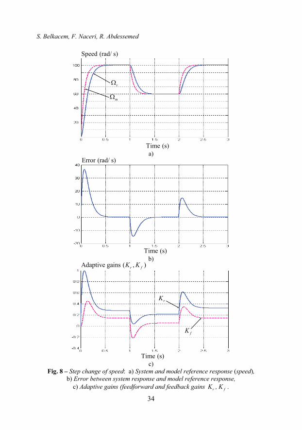
The system response, the model reference response, the adaptive gains and the error are shown respectively in Figs. 8a, 8b and 8c when the reference speed is a step reversing waveform whose repetition period is 1s, the magnitude of the reference speed is increased from 100 rad/s to 60 rad/s. at no load.

A Novel Robust Adaptive Control Algorithm and Application to DTC-SVM...
33
a)
b)
c)
Fig. 7 – Starting at no load: a) System and model reference response (speed), b) Error between system response and model reference response,
c) Adaptive gains (feedforward and feedback gains rK , fK ).
S. Belkacem, F. Naceri, R. Abdessemed
34
a)
b)
c)
Fig. 8 – Step change of speed: a) System and model reference response (speed), b) Error between system response and model reference response,
c) Adaptive gains (feedforward and feedback gains rK , fK .

A Novel Robust Adaptive Control Algorithm and Application to DTC-SVM...
35
d)
e)
f)
Fig. 8 – Step change of speed: d) Phase current sI , e) Electromagnetic torque eT , f) Stator flux magnitude.

S. Belkacem, F. Naceri, R. Abdessemed
36
a)
b)
c)
Fig. 9 – Switching on and off of constant load torque: a) System and model reference response (speed),
b) Error between system response and model reference response, c) Electromagnetic torque eT .

A Novel Robust Adaptive Control Algorithm and Application to DTC-SVM...
37
d)
Fig. 9 – Switching on and off of constant load torque: d) Phase current sI .
The system response, the model reference response, the error, electro-magnetic torque, and the current when load ( 10 NmrT = ) is switched on and off are shown respectively in Figs. 9a, 9b, 9c and 9d, when value of load is increased from 10 Nm to 0 Nm.
5.3 Results discussion The knowledge of plant parameters is not needed for: − The satisfaction of the positive realness condition (38); − The derivation of the MCS control input (30); − The satisfaction of Popov’s criterion (35) and (36).
A At no load ( 0 NmrT = )
The speed response is well damped within a rise time of 0.5s and a good agreement can be observed between system response and model reference response. (Fig. 7a).
The feedforward and the feedback gains change during speed transients and remain unchanged during steady state conditions. (Fig. 7c).
The error between the reference model and system is important during the transient state, and decay to zero during the steady-state conditions. The error is asymptotically stable. (Fig. 7b).
It can be seen that both feedforward and feedback gains are increased and decreased with speed reference. (Fig. 8c).
S. Belkacem, F. Naceri, R. Abdessemed
38
B Load Disturbance test ( 0 Nm 10 Nm 0 NmrT = − − )
The disturbance is slowly varying. In the load disturbance test shown in (Fig. 9), the AC drive is running in
steady-state while the load is switched on-off-on-off suddenly to generate rated sudden load changes.
6 Conclusion
This investigation presents a development of a new robust adaptive control strategy – the Minimum Control Synthesis algorithm for high performance AC drives. These developments have improved the conventional configuration in three respects:
• The proposed configuration has two states speed and acceleration. • Rejection of the effects of external disturbances. Therefore the error is
asymptotically stable. • The error output matrix C design is simplified (in a conventional MRAC
synthesis, C is generated according to Landau: T=C B P , where: T
m m+ = −PA A P Q . Obviously, an estimate of B is required. While it is not required in the case of MCS algorithm.
This MCS controller requires no plant model or controller gain synthesis. At present, the scalar parameters α and β are chosen empirically. The intention is to provide a priori design method for these parameters, based on a robustness study on the MCS closed-loop dynamics.
The stability of the proposed configuration has been proved asymptotically stable using the hyperstability theory.
Simulation studies were used to demonstrate the characteristics of the proposed method. It is shown that the proposed controller has better tracking performance and robustness against parameters variations.
Additionally, the application of SVM guarantee: • Constant inverter switching frequency; • Delimited distortion caused by sector changes; • Requirement of sampling frequency; • High robustness; • Good dynamic response; • Low complexity.

A Novel Robust Adaptive Control Algorithm and Application to DTC-SVM...
39
7 References
[1] I. Takahashi, Y. Ohmori: High-performance Direct Torque Control of Induction Motor, IEEE Transaction on Industry Application, Vol. 25, No. 2, Mar/Apr. 1989, pp. 257 – 264.
[2] D. Casadei, F. Profumo, G. Serra, A. Tani: FOC and DTC: Two Viable Schemes for Induction Motors Torque Control, IEEE Transaction on Power Electronics, Vol. 17, No. 5, Sept. 2002, pp. 779 – 787.
[3] T. Noguchi, M .Yamamoto, S. Kondo, I. Takahashi: High Frequency Switching Operation of PWM Inverter for Direct Torque Control of Induction Motor, Industry Application Conference, New Orleans, LA, Vol. 1, Oct. 1997, pp. 775 – 780.
[4] K.B. Lee, J.H Song, I. Choy, J.Y. Yoo: Torque Ripple Reduction in DTC of Induction Motor Driven by Three-phase Inverter with Low Switching Frequency, IEEE Transaction on Power Electronics, Vol. 17, No. 2, March 2002, pp. 255 – 264.
[5] N.J. Nash: Direct Torque Control Induction Motor Vector Control without an Encoder, IEEE Transaction on Industry Application, Vol.3, No. 2, Mar/Apr. 1997, pp. 333 – 341.
[6] C. Lascua, A.M. Trzynadlowski: Combining the Principles of Sliding Mode, Direct Torque Control and Space Vector Modulation, Industry Applications Conference, Vol. 3, Oct. 2002, pp. 2073 – 2079.
[7] Y.S. Lai, J.H. Chen: A New Approach to Direct Torque Control of Induction Motor for Constant Inverter Switching Frequency and Torque Ripple Reduction, IEEE Transaction on Energy Conversion, Vol.16, No. 3, Sept. 2001, pp. 220 – 227.
[8] D. Swierczynski, M.P. Kazmierkonwski: Direct Torque Control of Permanent Magnet Synchronous Motor (PMSM) using Space Vector Modulation (DTC-SVM) Simulation and Experimental Results, Conference of the Industrial Electronics Society, Vol. 1, Nov. 2002, pp. 751 – 755.
[9] G.R.A. Markadeh, J. Soltani: Robust Direct Torque and Flux Control of Adjustable Speed Sensorless Induction Machine Drive based on Space Vector Modulation using a PI Predictive Controller, Electrical Engineering, Vol. 88, No. 6, Aug. 2006, pp. 485 – 496.
[10] B. Akin: State Estimation Techniques for Speed Sensorless Field Oriented Control of Induction Motor, PhD Thesis, School of Natural and Applied sciences, Middle East Technical University, Aug. 2003.
[11] J. Golten, A. Verwer: Control System Design and Simulation, McGraw-Hill, 1991. [12] J.G. Ziegler, N.B Nichols: Optimum Settings for Automatic Controllers, Transaction of the
American Society of Mechanical Engineers, Vol. 65, Nov. 1942, pp. 759 – 768. [13] K.J. Astrom, T. Hagglund: Automatic Tuning of Simple Regulators with Specifications on
Phase and Amplitude Margins, Automatica, Vol. 20, No. 5, Sept. 1984, pp. 645 – 651. [14] F.J. Lim, C. Liaw: Reference Model Selection and Adaptive Control for Induction Motor
Drives, IEEE Transaction on Automatic Control, Vol. 38, No. 10, Oct. 1993, pp. 1594 – 1600. [15] Y. Wen, C. Soh: A Unified Approach for the Analysis and Design of Robust Adaptive
Control Systems, 35th Conference on Decision and Control, Kobe, Japan, Dec. 1996, pp. 1922 – 1927.
[16] R.D. Lorenz, D.B. Lawson: A Simplified Approach to Continuous, On-line Tuning of Field Oriented Induction Machines Drives, IEEE Industry Application Society Meeting, Vol. 1, Oct. 1988, pp. 444 – 449.

S. Belkacem, F. Naceri, R. Abdessemed
40
[17] C.A. Winsor, R.J. Roy: The Applications of Specific Optimal Control to the Design of Desensitised Model Following Control Systems, IEEE Trans. On Automatic Control, vol. 15, No. 3, June 1970, pp. 326 – 333.
[18] Y.D. Landau: Adaptive Control – The Model Reference Approach, New York, Marcel Dekker, 1979.
[19] S. Belkacem, F, Naceri, R. Abdessemed: Improvement in DTC-SVM of AC Drives using a New Robust Adaptive Control Algorithm, International Conference on Sciences and Techniques of Automatic control and Computer Engineering, Hammamet, Tunisia, Dec. 2009, pp. 751 – 765.
[20] D.P. Stoten, H. Benchoubene: Empirical Studies of an MRAC Algorithm with Minimum Controller Synthesis, International Journal of Control, Vol. 51, No. 4, Apr. 1990, pp. 823 – 849.
[21] D.P. Stoten, H. Benchoubene: Robustness of a Minimum Controller Synthesis, International Journal of Control, Vol. 51, No. 4, Apr. 1990, pp. 851 – 861.
[22] F. Naceri, S. Belkacem: A New Robust Approach to MCS Algorithms. Application to an AC Machine, Archives of Electrical Engineering, Vol. 55, No. 2, 2006, pp. 163 – 178.
[23] F. Naceri, L. Abida: A Novel Robust Adaptive Control Algorithm for AC Drives, Computers and Electrical Engineering, Vol. 29, No. 4, June 2003, pp. 523-534.
[24] K.S. Narendra, L.S. Valavani: A Comparison of Lyapunov and Hyperstability Approaches to Adaptive Control of Continuous Systems, IEEE Transaction on Automatic Control, Vol. 25, No. 2, Apr. 1980, pp. 243 – 247.
[25] Y.C. Wen, Y.C. Soh: Unified Approach for the Analysis and Design of Robust Adaptive Control Systems, 35th Conference on Decision and Control, Kobe, Japan, Dec. 1996, pp. 1922 – 1927.
[26] M. Kadjoudj, N. Golea, M. El. H. Benbouzid: Fuzzy Rule-based Model Reference Adaptive Control for PMSM Drives, Serbian Journal of Electrical Engineering., Vol. 4, No. 1, June 2007, pp. 13 – 22.