a new reconstruction method for 3d buildings from 2d
TRANSCRIPT
HAL Id: hal-00920680https://hal.inria.fr/hal-00920680
Submitted on 19 Dec 2013
HAL is a multi-disciplinary open accessarchive for the deposit and dissemination of sci-entific research documents, whether they are pub-lished or not. The documents may come fromteaching and research institutions in France orabroad, or from public or private research centers.
L’archive ouverte pluridisciplinaire HAL, estdestinée au dépôt et à la diffusion de documentsscientifiques de niveau recherche, publiés ou non,émanant des établissements d’enseignement et derecherche français ou étrangers, des laboratoirespublics ou privés.
A new reconstruction method for 3D buildings from 2Dvector floor plan
Junfang Zhu, Hui Zhang, Yamei Wen
To cite this version:Junfang Zhu, Hui Zhang, Yamei Wen. A new reconstruction method for 3D buildings from 2D vectorfloor plan. Computer-Aided Design and Applications 2013, Jun 2013, Lombary, Italy. �hal-00920680�

Computer-Aided Design & Applications, 10(a), 2013, bbb-ccc © 2013 CAD Solutions, LLC, http://www.cadanda.com
1
A new reconstruction method for 3D buildings from 2D vector floor plan
Junfang Zhu1,2,3, Hui Zhang1,2,3 and Yamei Wen1,2,3
1 School of Software, Tsinghua University, 2Tsinghua National Laboratory for Information Science and Technology 3Key Laboratory for Information System Security, Ministry of Education
[email protected], [email protected], [email protected]
ABSTRACT
This paper proposes a method to analyze the geometry and semantic information of 2D vector floor plans, and reconstruct the corresponding 3D building models automatically. First, the Shape-opening graph (SOG) is introduced to recognize Structural Components (SCs) and describe the relationships between SCs and openings which are architectural components separating spaces. A priority principle algorithm is developed to replace openings with wall equivalent lines for the purpose of later loop searching. Then, we present an odd-even-based edge breaking algorithm to preprocess wall lines in order to search loops directly and exactly. After that, all the interior-space contours, which are in fact rooms or aisles, and exterior boundary contour can be obtained. With the hierarchical component tree presented, the topological relations of the whole building can be obtained. Finally, 3D models can be generated after extruding loops to the wall height and cutting openings from the walls. A drawing with several floor plans can also be reconstructed to multi-floor building after aligning their dimensions. Moreover, the intermediate result after analyzing the 2D floor plan can be the input of other architectural software to generate 3D models.
Keywords: 3D reconstruction, vector floor plan, space information DOI: 10.3722/cadaps.2013.xxx-yyy
1 INTRODUCTION
2D architectural floor plans are a standard way to express design by architects and are widely used in the field of architecture. Fig. 1 is a real 2D vector architectural floor plan. 3D building models are intuitive and also support many applications. Using 3D building models for fire simulations can give valuable insight into building usability and safety [8]. Rendering on 3D building models makes the building more realistic. The popularity of navigation through virtual 3D environments is also rapidly growing. However, creating the 3D model of a set of floor plans manually is nontrivial and requires skill and time [15]. So conversion of 2D floor plans into 3D models automatically is of great significance.

Computer-Aided Design & Applications, 10(a), 2013, bbb-ccc © 2013 CAD Solutions, LLC, http://www.cadanda.com
2
Fig. 1: An example of architectural floor plan.
A building in real life is usually composed of many functional spaces, such as rooms, corridors, etc. Functional spaces are separated by walls, and openings such as doors and windows. Corresponding to the 2D architectural floor plan, functional spaces are presented by loops which are made up of wall lines and openings. So, reconstructing a 2D architectural floor plan to 3D model has three main tasks: 1) recognizing component symbols such as walls, doors, windows; 2) loop searching to get space information; 3) extrusion to get the finally 3D models.
Since vector architectural floor plans from real-life are in various styles, we assume that a typical architectural floor plan has the following characteristics:
� There are only lines, arcs and text existing in the drawing. Other types of graphic items, such as POLYLINEs, are converted into lines and arcs first in our preprocessing automatically.
� Structural Components like walls and openings like doors can-not be isolated. They must be connecting to or near to other openings or Structural Components.
The rest of this paper is organized as follows. Related work is summarized in Section2. Section 3 presents the Shape-opening graph (SOG) to detect walls and create wall equivalent lines for openings. In Section 4, we describe loop searching method to get space information and build the topological tree. Experimental results are shown in Section 5. Finally, we conclude the paper in Section 6.
2 RELATED WORK
There are two main formats for the existing architectural floor plans: digitally scanned format and vector format. Some early architectural drawings are drawn on papers. These drawings have been kept and handed down in the format of raster image. As far as we know, almost all the existing methods convert the raster image into vector format first, except [1] which processed directly on the raster images to analyze drawing and recognize symbols. Ah-Soon [2, 3] proposed a network-based method to recognize architectural symbols. Dosch [5, 6] presented a system for the analysis of architectural drawings. They designed a method for dividing large image into tiles, each of them being processed and analyzed independently. Or [12] proposed a highly automated approach to generate 3D model from a 2D floor plan. It assumed that two polylines with opposite propagating directions and in a certain distance should correspond to a wall. Kishen [11] devised a 3-Phase recognition approach to generate 3D building from 2D floor plan. They used clustering technique to group lines into bounding boxes, each representing a potential wall. Park [13] suggested a method for recognizing main walls based on extension lines, assuming that a main wall contains an auxiliary dimension line inside it. This kind of methods rely heavily on the robustness of the vectorization algorithm and focus on low-level
Computer-Aided Design & Applications, 10(a), 2013, bbb-ccc © 2013 CAD Solutions, LLC, http://www.cadanda.com
3
process, i.e., segmentation, detection of arc from scanned drawings. Because all the exiting vectorization methods are not good enough, these methods usually involves human interactions.
Since 1990s, architectural drawings produced by CAD software (e.g. AutoCAD) have become popular, making the storage, editing and processing of data much easier than before. Therefore, in this paper we only focus on the reconstruction of vector architectural floor plans.
So [14] first incorporated automated approaches to the three streams to accomplish the reconstruction goal: wall extrusion, object mapping, and ceiling and floor reconstruction. The processing time has been shrunk approximately 10% to 15% of the overall manual tasks, but it still needs a lot of manual work.
Lewis [8] developed a semi-automatic system to create 3D polyhedral building models from AutoCAD DXF geometry description format. The system has utilised room label as seed point to find interior space contours and replaced each door symbol with two separate edges. Because of extruding each edge separately, the system still needs a few days to accomplish a building under some sort of human intervention.
Zhi [16] presented an automatic approach to transfer computer-dawn architectural plans into a building fire evacuation simulator model. The system assumed that the drawing is a combination of units and a unit is a combination of loops. They searched loops using a graph directly in the drawing under suitable layers. The limitation is that this system can’t handle drawings composed of complicated graphical primitives.
Dom´�nguez [4] presented a method for detecting the topology of building floors semi-automatically. The method involves the detection of walls and joint points amid walls and openings, and the search of intersection points amid walls. For the representation of opening with wall segments, it must involve user interaction and they assumed that doors and windows are represented by blocks.
Lu developed systems to construct models from computer-drawn construction structural drawings [9] and architectural working drawings [10] which have no labels to indicate component types. Based on the three types of the most frequently occurring shapes T, X, L, it detects parallel line-segment pairs as walls and removes them from the drawing. The remaining architectural symbols are detected by finding features that match with predefined patterns.
In this paper, we focus on getting the topological and semantic information of spaces as well as generating 3D models after analyzing 2D architectural floor plans. The hierarchy tree which presents the relationships among space and architectural components is also created for some applications and being output to other software. We can also construct multi-floor 3D models after analyzing the 2D architectural drawing of its floors by matching their axes in the drawing.
3 COMPONENT SYMBOL RECOGNITION
2D architectural floor plans contain inner spaces such as rooms and corridors, and the outer contour of building. Different spaces are separated by walls and openings. Therefore, after all basic geometric elements are obtained from vector architectural floor plans, we first recognize openings such as doors, windows, decorative components such as furnitures, and Structural Components such as walls before reconstruction.
3.1 Decorative Symbol Recognition
Definition 1 (Wall Side): The direction of a wall is from the lower left points to the upper right points of its wall lines. The left or right side of the wall direction is called the Wall side.
After openings and decorative components were recognized by the symbol recognition algorithm based on key features proposed by Guo [7], more semantic information of some key symbols, such as doors, slide doors windows and bay windows, is analyzed in order to provide basis for more realistic
3D models.
The semantic information of door is facing direction and door-axis. The facing direction can be obtained from determining its Wall Side while door-axis can be determined according to the position of the arc and wall lines beside the door. Fig. 2(a) is a door symbol. It faces upside and its door-axis is

Computer-Aided Design & Applications, 10(a), 2013, bbb-ccc © 2013 CAD Solutions, LLC, http://www.cadanda.com
4
on the left as Fig. 2(e) shows. Based on the position of the wall next to the door-axis, a rectangle (red lines in Fig. 2(e)) to represent the 2D model of the door is created. The length of the rectangle is the radius length of the arc and the width is a default value.
Fig. 2(b) is a slide door symbol. The 2D model of slide door is two adjoining rectangles which share a vertex and have two edges on the same line as Fig. 2(f) shows. The length of each rectangle is half length of the slide door and the width is half the thickness of the wall.
Fig. 2(b) is a window symbol. The orientation is the semantic information of window. We just use two rectangles to represent window sashes as shown in Fig. 2(g). The window sashes must be facing the outside of the room it’s in. The length of each rectangle is half length of the window and the width is a default value.
Fig. 2(g) is a bay window and its 2D model is two rectangles as Fig. 2(f) shows. The two rectangles are overlapping with the lines of bay window.
All these semantic rectangles will not be used for recognizing walls in Section 3 and searching loops of spaces in Section 4. They are for constructing 3D models for openings in Section 5.
(a) Door (b) Slide door (c) Window (d) Bay window
(e) (f) (g) (f)
Fig. 2: Semantic information of key symbols
3.2 Wall Element Identification
After openings and decorative symbols are recognized, Structural Components are then detected in the remaining basic geometric elements. In vector floor plans, Structural Components, such as walls and beams, are usually presented by two parallel lines (PP). Because a large number of other parallel lines such as dimensions exist, detecting two parallel lines within a certain distance directly in the drawing cannot be used to identify walls.
Through analysis of PPs, Lu [5] proposed a method to detect walls by recognizing the three types L, T, X at the intersection of walls. Besides these three types, we find another shape I which is actually a wall not intersecting with other walls, which means it has openings on its both sides. The I shape is represented as a rectangle which is made up of two pairs of PPs intersecting at the endpoints of each PP line in 2D floor plans.
Definition 2 (Basic Structural Element): The four types of wall shapes and openings are defined as Basic Structural Elements.
In this paper, Between the Basic Structural Elements there are three relationships: � Shape and Shape Intersecting (SSI). For shapes S
1 and S
2, if there exists a PP which is belong to
both S1 and S
2, then S
1 and S
2 are SSI.
� Shape and Opening Adjacent (SOA). The shape S and opening O are adjacent if and only if their distance Dis(S, O)� L
diagonal. L
diagonal is the diagonal length of the bounding box of O. Dis(S,O) is
defined as: Dis(S,O)=min{Dis(Li, P
Center)}, L
i is the PP line of S, i ranges from 1 to the number of
lines in S , Pcenter
is the center point of the bounding box of O.
Computer-Aided Design & Applications, 10(a), 2013, bbb-ccc © 2013 CAD Solutions, LLC, http://www.cadanda.com
5
� Opening and Opening Adjacent (OOA). Two openings O1 and O
2 are adjacent if and only if their
distance Dis(PCenter1
, PCenter2
) � Ldiagonal2.
PCenter1
and PCenter2
are the center point of the bounding box of O
1 and O
2 respectively, L
diagonal2 is the sum of the diagonal length of the two bounding boxes
After analyzing a large number of drawings, we find that each Basic Structural Element must have one or more neighboring Basic Structural Elements. That means X, L, T shapes either intersect with other shapes or be adjacent to openings, and I shape has openings at its both sides. An opening is adjacent to shapes or other openings. Based on such basis, openings that have already been recognized can be used to identify walls.
We introduce the Shape-Opening Graph SOG = (N, E), where N is a node set and E is an edge set. Nodes in the graph are one-to-one corresponding to the Basic Structural Elements and edges present the relationships between Basic Structural Elements. The graph generation process is the process of identifying PPs as well as building the topological relationships between PPs and openings. The outline of the algorithm is: First, select any of the recognized openings as the initial node of SOG. Then add nodes that have relationships with nodes in SOG and create edges between them. Recursive these two processes until all the openings are added to SOG.
The shapes in SOG are obtained in the following method: The three shapes T, L and X can be recognized using the algorithm of Lu [14] and the I shape can be got from the intersecting PPs as follows: If there are two PPs, P1 and P2, and the endpoints of the two lines in P1 are the endpoints of the two lines in P2, then P1 and P2 form an I shape.
After the SOG is established, each PP in SOG makes up a wall and the lines of a PP are called wall lines.
Fig. 4(a) is the original architectural floor plan. Fig. 4(b) shows the recognized shapes and wall lines. In Fig. 4(b), there are several shapes not intersecting with others, as the blue shapes shown in Fig. 4(b), our method can identify them correctly, while they can not be handled by the algorithm proposed by Lu [14].
3.3 Wall Equivalent Lines
Because walls are cut off by openings, several recognized PPs may represent the different parts of the same wall. In order to restore the integrity of the wall, we introduce the Wall Equivalent Lines (WELs) to replace openings. A WEL is represented by two parallel lines in the position of the opening to connect its adjoining wall PPs.
Besides an opening has walls at its both sides, there also exist two or more openings adjoining side by side in real architectural floor plans, which means, opening A adjoins opening B, or even B adjoins another opening C. If there are more than one opening adjoining, we need to merge them first to take them as a whole for follow-up processing.
Creating wall equivalent lines for an opening can be achieved by calculating its nearest PPs. Every opening keeps its nearest PPs in a set NP. If the number of PPs in the NP set of the opening is greater than 2, extra operation needs to be carried out by our following priority-based principles.
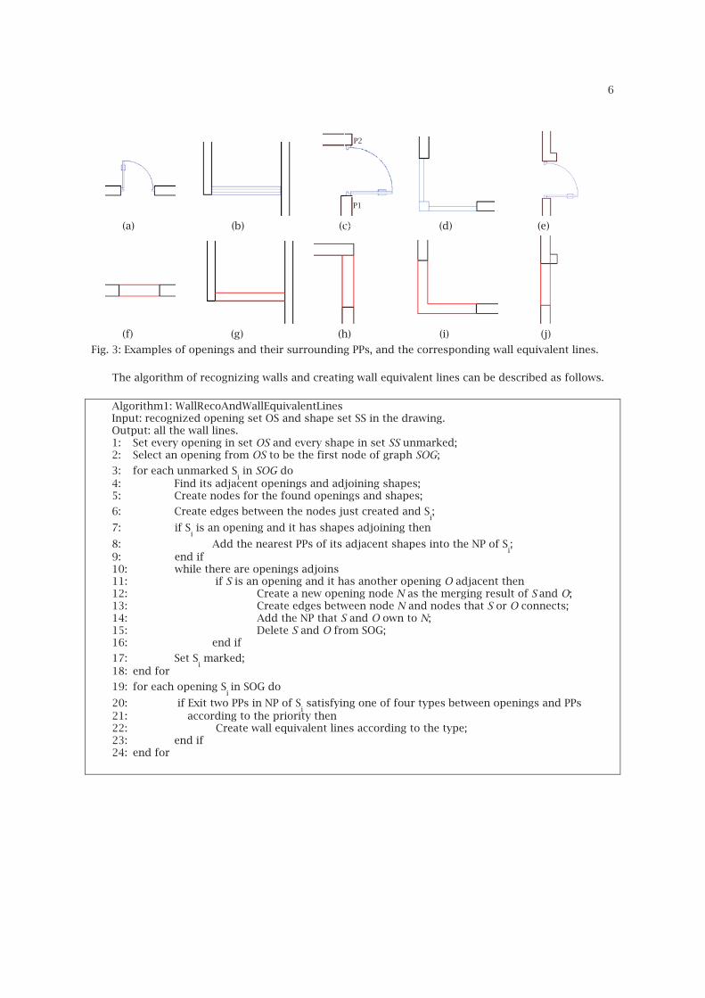
1). If the opening is between two parallel PPs which are in the same line (Fig. 3(a)), create the wall equivalent lines by extending the two lines of one PP to the other as shown in Fig. 3(f)
2). If the opening is between two parallel PPs which are not in the same line (Fig. 3(b)), the center point of the bounding box of the opening is first calculated, followed by creating two parallel edges which are half of wall’s thickness away from the center point and perpendicular to the parallel PPs (Fig. 3(g)).
3). If the opening is between two perpendicular PPs and the projection of P1 to P2 is in P2 (Fig. 3(c)), extend P1 until it meets P2 (Fig. 3(h)).
4). If the opening is between two perpendicular PPs whose intersection is in their extended lines (Fig. 3(d)), extend both of the PPs until they intersect (Fig. 3(i)).
The wall equivalent lines added are shown in red in Fig. 3(f)-Fig. 3(j). The priorities of the above situations are decreasing by the narrating order, that is, only if there are no PPs satisfying the first type, the second type could be considered. For example, Fig. 3(e) satisfies both type 1) and 3), but we handle it as type 1) just because its priority is higher.
Computer-Aided Design & Applications, 10(a), 2013, bbb-ccc © 2013 CAD Solutions, LLC, http://www.cadanda.com
6
P1
P2
(a) (b) (c) (d) (e)
(f) (g) (h) (i) (j)
Fig. 3: Examples of openings and their surrounding PPs, and the corresponding wall equivalent lines.
The algorithm of recognizing walls and creating wall equivalent lines can be described as follows.
Algorithm1: WallRecoAndWallEquivalentLines Input: recognized opening set OS and shape set SS in the drawing. Output: all the wall lines. 1: Set every opening in set OS and every shape in set SS unmarked; 2: Select an opening from OS to be the first node of graph SOG;
3: for each unmarked Si in SOG do
4: Find its adjacent openings and adjoining shapes; 5: Create nodes for the found openings and shapes;
6: Create edges between the nodes just created and Si;
7: if Si is an opening and it has shapes adjoining then
8: Add the nearest PPs of its adjacent shapes into the NP of Si;
9: end if 10: while there are openings adjoins 11: if S is an opening and it has another opening O adjacent then 12: Create a new opening node N as the merging result of S
and O;
13: Create edges between node N and nodes that S or O connects; 14: Add the NP that S and O own to N; 15: Delete S and O from SOG; 16: end if
17: Set Si marked;
18: end for
19: for each opening Si in SOG do
20: if Exit two PPs in NP of Si satisfying one of four types between openings and PPs
21: according to the priority then 22: Create wall equivalent lines according to the type; 23: end if 24: end for
P2
P1
Computer-Aided Design & Applications, 10(a), 2013, bbb-ccc © 2013 CAD Solutions, LLC, http://www.cadanda.com
7
The time complexity of recognizing the types between PPs is O(N2), where N is the number of lines in the drawing. The time complexity of creating SOG graph is O(T2), where T is the total number of the
four kinds of types and openings in the drawing. The time complexity of creating Wall Equivalent Lines is O(D*W2). D is the number of openings and W is the number of wall PPs in the drawing. So the time complexity of Algorithm 1 is O(N2) + O(T2) + O(D*W2).
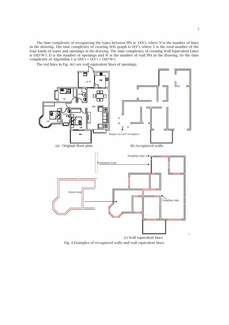
The red lines in Fig. 4(c) are wall equivalent lines of openings.
(a) Original floor plan (b) recognized walls
(c) Wall equivalent lines
Fig. 4 Examples of recognized walls and wall equivalent lines.
Dangling edge
Dangling edge
Room loop
Redundant loop
Shapes Lu can’t recognize

Computer-Aided Design & Applications, 10(a), 2013, bbb-ccc © 2013 CAD Solutions, LLC, http://www.cadanda.com
8
4 LOOP SEARCH TO GET SPACE INFORMATION
4.1 Preprocessing For Loop Searching
Definition 3 (InnerPoint): If a wall line meets another one at a non-endpoint, this intersecting vertex is called InnerPoint.
If searching loops directly among the wall lines and WELs, different types of loops may be detected: loops of functional spaces (rooms, corridors, outer contour), wall contour (redundant loops) and loops with no semantic information (error loops). But some loops, which should be searched, couldn’t be found out. For example, in Fig. 4(c), the left red loop presents a room. The left green loop is a wall contour which is redundant. The outer contour of the building couldn’t be found because of the dangling edge.
In order to ensure that all the searched loops have semantic meaning, e.g. each loop is a functional space, we preprocess the wall lines and wall equivalent lines got in Section 3 if the intersections of them are not their endpoints (see Fig.5) or there exists dangling wall lines which means the degree of one endpoint of a wall line is 1 as Fig.6 shows. After the preprocessing, the edges and vertices satisfy the following two conditions:
� Adjacent edges only intersect at their start or end points. � The degree of each vertex is 2, i.e. every vertex connects two edges.
In order to remove the InnerPoint, we propose an odd-even-based method to break wall lines. For the case of odd InterPoint(s), as shown in Fig.5(a), if wall line W1 intersects with other wall lines at P1 and E1, line segment P1E1 should be deleted in order to eliminate the InnerPoint P1, as Fig.5(b) shows. If the number of interPoints in a wall line WL is n and n is odd, the number of walls crossing WL is (n+1)/2. n/2 walls have two InnerPoints in WL and one wall has an InnerPoint wall thickness away from one of the endpoints.
For the case of even InterPoint(s), as shown in Fig.5(c), if wall line W1 intersects with wall line W2 and W4 at the InnerPoints P1 and P2, line segment P1P2 should be deleted and wall line W1 is separated into two wall lines, as Fig.5(d) shows. If the number of interPoints in a wall line WL is n and n is even, the number of walls crossing WL can be n/2 or n/2+1. The former one means that all the walls crossing WL has two interPoints in WL. The latter one means that besides n/2-1 number of walls having two interPoints with WL, there are also two walls crossing WL with one interPoint.
For each wall line, the interPoints array VR is first calculated. According to the number of VR, we implement the algorithm 2.
(a) One InnerPoint (b) Breaking result for (a) (c) Two InnerPoints (d) Breaking result for (c)
Fig. 5: Examples of preprocess for loop searching
Algorithm 2: OddEvenBreakingEdge. Input: WL: wall lines in floor plan F. Output: WL: wall lines in floor plan F after processing.
1: for each wli in WL do
2: Compute the interPoints array VR in wli;
3: Compute the wall thickness t of the wall which wli belongs to;
4: if (the number of VR is even) then
5: for each vri in VR do
6: if there exists a vertex vrj
t away from vri then
7: Create an edge e from vri to the endpoint near it
P1
W4 E1
W2
W3 W1
W4
W2
W1W3
P2
P1
Computer-Aided Design & Applications, 10(a), 2013, bbb-ccc © 2013 CAD Solutions, LLC, http://www.cadanda.com
9
8: Create an edge d from vri to the other point;
9: Add e, d into WL;
10: Delete wli from WE;
11: Delete from vri, vr
j from VR;
12: OddEvenBreakingEdge(); 13: else
14: if distance between vri and one endpoint ep is t then
15: Create an edge e from vri to the other endpoint;
16: Add e into WL;
17: Delete wli from WL;
18: Delete from vri from VR;
19: OddEvenBreakingEdge(); 20: else
21: for each vri in VR do
22: if distance between vri and one endpoint ep is t then
23: Create an edge from vri to the other endpoint;
24: Add e into WL;
25: Delete wli from WL;
26: Delete from vri from VR;
27: OddEvenBreakingEdge();
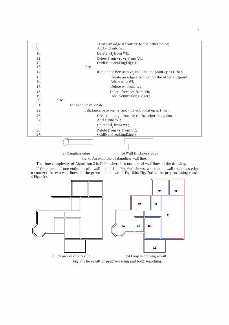
(a) Dangling edge (b) Wall thickness edge
Fig. 6: An example of dangling wall line.
The time complexity of Algorithm 2 is O(L2), where L is number of wall lines in the drawing.
If the degree of one endpoint of a wall line is 1 as Fig. 6(a) shows, we create a wall-thickness edge to connect the two wall lines, as the green line shown in Fig. 6(b). Fig. 7(a) is the preprocessing result of Fig. 4(c).
(a) Preprocessing result (b) Loop searching result
Fig. 7: The result of preprocessing and loop searching.

Computer-Aided Design & Applications, 10(a), 2013, bbb-ccc © 2013 CAD Solutions, LLC, http://www.cadanda.com
10
4.2 Searching Loop
After preprocessing, there are two kinds of loops in the floor plan: inner loop, which indicates spaces, typically rooms and corridors, and the outer contour. Because the degree of each vertex is 2, using any vertex that has not been traversed as the first vertex, travelling in the counterclockwise direction, all the loops can be obtained. The loop containing the minimum value of x or y is the outer loop. Fig. 7(b) shows an example of searched loops. The red loop is the outer loop and the blue loops are the inner loops. The time complexity of searching loops T4 is O(L).
4.3 Semantic Analysis Of Space
Definition 4 (Adjacent Space): If two spaces have a common wall and they can be accessed through a door, they are Adjacent Spaces. For example, in Fig. 7(b), the Adjacent Spaces of inner space S1 are S2, S3, S4, S5, S6, S8.
Definition 5 (Space Distance): For two spaces S1 and S2, their Space Distance SD = SD1 + SD2. SD1 is the distance between the center point of S1 and their common door. SD2 is the distance between the center point of S2 and the door. Specially, if a space A has a door to outside, its distance to outside area is the distance between the center point of A and the door.
With the text in the drawing, we can get the semantic meaning of each space like parlor, dining room and bedroom. A hierarchical component tree is established to describe the topological relations of the building and the root is the building itself. The second layer of the tree is semantic spaces, such as rooms and corridors, and the outer contour. Each space contains a pointer pointing to its Adjacent Spaces. The third layer of the tree is walls and openings. Each wall contains the openings in it.
The hierarchy tree is useful in many applications. It can be saved and put to other software such as REVIT to construct 3D models. It also can be used to generate target path for fire evacuation system. To find the shortest path from an inner space to outside, a travel-graph TG = (N, E) is created, where N is a node set and E is an edge set. Each node presents an inner space or the outside area. If two spaces are Adjacent Spaces, an edge is created between the two corresponding nodes. The weight of each edge is the Space Distance of the two spaces. The nearest path from an inner space to the outer area can be obtained using the Dijkstra algorithm.
5 3D EXTRUSION AND EXPERIMENTAL RESULTS
5.1 Single Floor Extrusion
The final 3D model can be obtained by the following steps:
(1) Extruding the outer loop to the wall height to form the original 3D model.
(2) Cutting the inner loops from above 3D model.
(3) Building the floor according to the inner loops.
(3) Cutting openings from the model.
(4) Building the 3D models of doors, slide doors, windows, bay windows as follows: � The 3D model of door is created by extruding its 2D rectangle loop model from the bottom of
the space to the default height of door. � The 3D model of slide door is created by extruding its 2D rectangle loop model from the
bottom of the space to the default height of slide door. � The 3D model of window is created by extruding its two 2D rectangle loops from the window
base to the window ceil. � The 3D model of bay window is created by extruding it outer loop and minus the inner loop.
Fig. 8(a) is the wall extrusion result. Fig. 8(b) is the 3D model after cutting openings. Fig. 8(c) is the final model of the Fig. 4(a). Fig. 9(a) is a bigger floor plan and Fig. 9(b) is its corresponding 3D model.

Computer-Aided Design & Applications, 10(a), 2013, bbb-ccc © 2013 CAD Solutions, LLC, http://www.cadanda.com
11
(a) Extrusion of walls (b) Cutting openings
(c) Final result (d) A 3D model of multi-floor
Fig. 8 Example of the final 3D model.
(a) A real floor plan (b) 3D model of (a)
Fig. 9 A bigger example.
Computer-Aided Design & Applications, 10(a), 2013, bbb-ccc © 2013 CAD Solutions, LLC, http://www.cadanda.com
12
5.2 Multi- Floor Model Reconstruction
The 3D structure of a building can be obtained by analyzing the 2D architectural drawings of its floors. Every floor is aligned to the first floor by matching their axes in the drawing. An axis has one axis line connected to a circle with text, e.g. Axis (line, circle, text).
There are four types of axes: � Horizontal-left: The line of the axis is horizontal and the text of the axis is on the left of the
drawing. � Horizontal-right: The line of the axis is horizontal and the text of the axis is on the right of the
drawing. � Vertical-up: The line of the axis is vertical and the text of the axis is on the upside of the
drawing. � Vertical-down: The line of the axis is vertical and the text of the axis is under the drawing.
Definition 6 (Equal Axes): Two axes in different floor plans are equal axes if and only if they are of the same type and their texts are the same.
To align more than one floor plan is to match the Equal Axes in these floor plans. Take two floors as the example, the steps of aligning floor F2 to F1 is as follows:
(1) Find all the axes of each floor plan. (2) Determine the type of each axis. (3) Select a horizontal axis h1 in F1, find its equal axis h2 in F2. (4) Select a vertical axis v1 in F1, find its equal axis v2 in F2. (5) Move (x2-x1, y2-y1) for F2 to F1, where y1 and y2 are the y coordinate values of h1 and h2, x1
and x2 are the x coordinate values of v1 and v2.
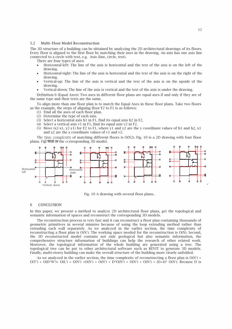
The time complexity of matching different floors is O(N2). Fig. 10 is a 2D drawing with four floor plans. Fig. 8(d) is the corresponding 3D model.
Fig. 10 A drawing with several floor plans..
6 CONCLUSION
In this paper, we present a method to analyze 2D architectural floor plans, get the topological and semantic information of spaces and reconstruct the corresponding 3D models.
The reconstruction process is very fast and it can reconstruct a floor plan containing thousands of geometric primitives in several minutes because of using the loop extruding method rather than extruding each wall separately. As we analyzed in the earlier section, the time complexity of reconstructing a floor plan is O(N2). The working space needed for the reconstruction is O(N). Second, the 3D reconstructed model contains not only geological but also semantic information, the comprehensive structure information of buildings can help the research of other related work. Moreover, the topological information of the whole building are generated using a tree. The topological tree can be put to other architectural software such as REVIT to generate 3D models. Finally, multi-storey building can make the overall structure of the building more clearly unfolded.
As we analyzed in the earlier section, the time complexity of reconstructing a floor plan is O(N2) + O(T2) + O(D*W2)+ O(L2) + O(N2) <O(N2) + O(N2) + D*O(N2) + O(N2) + O(N2) = (D+4)* O(N2). Because D is
Horizontal- left
Vertical- up
Horizontal- right
Vertical- down
Computer-Aided Design & Applications, 10(a), 2013, bbb-ccc © 2013 CAD Solutions, LLC, http://www.cadanda.com
13
usually a much smaller number than N (usually 100*D<N), so the time complexity of reconstructing a floor plan is O(N2). The working space needed for the reconstruction is O(N2).
Many existing methods need semantic information in the drawing when recognizing architectural components such as walls [8] , in [4] the openings should be in blocks. Instead, our method can handle drawings without any additional information when recognizing walls in Section 3.2. After recognition of components, the 3D extrusion using loop extrusion method is faster than many of the existing algorithm, such as [8] who extruded each wall respectively. The time complexity of extra loop searching step is O(W), which is much smaller than extrusion and bollean operation.
Further research includes recognizing isolated walls not adjacent with any components, handling drawings with columns and beams, improving the efficiency of the algorithm and matching different floors with no axes.
ACKNOWLEDGMENTS This work was supported by the 973 Program of China (2010CB328001), the National Nature Science Foundation of China (60903106, 61035002), the 863 Program of China (2012AA040902) and Tsinghua University Initiative Scientific Research Program (2012Z02170).
REFERENCES
[1] Ahmed, S.; Liwicki, M.; Weber, M.; Dengel, A: Improved Automatic Analysis of Architectural Floor Plans, International Conference on Document Analysis and Recognition (ICDAR), 2011, 864–869.
[2] Ah-Soon, C.; Tombre, K: Network-based recognition of architectural symbols, Advances in Pattern Recognition, 1451, 1998, 252–261.
[3] Ah-Soon, C.; Tombre, K.; Razdan, A.: Variations on the analysis of architectural drawings, Proceedings of 4th International Conference Document Analysis Recognition, 29(1), 1997, 20–30.
[4] Dom´�nguez B.; Garc´�a, A.L; Feito, FR: Semiautomatic detection of floor topology from CAD
architectural drawings, Computer-Aided Design, 44(5), 2012, 367–378. [5] Dosch, P.; Masini, G: Reconstruction of the 3D Structure of a Building from the 2D Drawings of
its Floors, Proceedings of the Fifth International Conference on Document Analysis and Recognition, 2005, 487–490.
[6] Dosch, P.; Tombre, K; Ah-Soon, C., Masini, G: A complete system for the analysis of architectural drawings, International Journal on Document Analysis and Recognition, 3(2), 2000, 102–116.
[7] Guo, T.; Zhang, H.; Wen, Y: An Improved Example-Driven Symbol Recognition Approach in Engineering Drawings., Computers & Graphics, 36(7), 2012, 835–845.
[8] Lewis, R.; S´equin, C: Generation of 3D building models from 2D architectural plans, Computer-Aided Design, 30(10), 1998, 765–779.
[9] Lu, T.; Tai, C.L.: Su, F.; Cai, S: A new recognition model for electronic architectural drawings, Computer-Aided Design, 37(10), 2005, 1053–1069.
[10] Lu, T.; Huafei Yang; Ruoyu Yang; Shijie Cai: Automatic Analysis and Integration of Architectural Drawings, Document Analysis and Recognition, 9(1), 2007, 31-47.
[11] Kishen Moloo, R.; jmal Sheik Dawood, M.; Salmaan Auleear A.: 3-Phase Recognition Approach to Pseudo 3D Building Generation from 2D Floor Plan, International Journal of Computer Graphics & Animation, 1(2), 2011, 13-27.
[12] Or, S.; Wong, KH; Yu, Y.; Chang, M.M.; Kong, H: Highly automatic approach to architectural floor plan image understanding and model generation, Proc. Vision, Modeling, and Visualization, IOS Press, 2005, 723-734.
[13] Park, J.; Kwon, Y.B: Main wall recognition of architectural drawings using dimension extension line, Graphics Recognition, Recent Advances and Perspectives, LNCS 3088, 2004, 116–127.
[14] So, C.; Baciu, G.; Sun, H: Reconstruction of 3D virtual buildings from 2D architectural floor plans, Proceedings of the ACM symposium on Virtual reality software and technology, 6754(2), 1998, 17–23.
[15] Yin, X.; Wonka, P.; Razdan, A: Generating 3d building models from architectural drawings: A survey, Computer Graphics and Applications, 29(1), 2009, 20–30.
Computer-Aided Design & Applications, 10(a), 2013, bbb-ccc © 2013 CAD Solutions, LLC, http://www.cadanda.com
14
[16] Zhi, GS; Lo, SM; Fang, Z: A graph-based algorithm for extracting units and loops from architectural floor plans for a building evacuation model, Computer-Aided Design, 35(1), 2003, 1–14.