a new gas dispersion impeller with vertically asymmetric ... · a new gas dispersion impeller with...
TRANSCRIPT
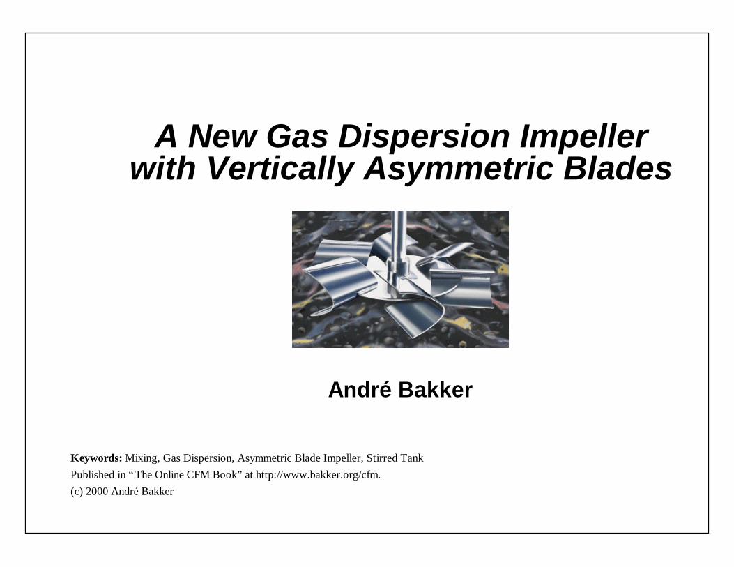
A New Gas Dispersion Impellerwith Vertically Asymmetric Blades
André Bakker
Keywords: Mixing, Gas Dispersion, Asymmetric Blade Impeller, Stirred TankPublished in “The Online CFM Book” at http://www.bakker.org/cfm.(c) 2000 André Bakker

Acknowledgment
u Fluent Inc.:Ø Lanre OshinowoØ Liz Marshall
u Chemineer, Inc.:Ø Mark ReederØ Julian Fasano
u University of Dayton:Ø Kevin MyersØ Aaron Thomas

Abstract
For several decades the so-called Rushton turbine was the standard impeller for gas dispersionapplications. It features six flat blades mounted on a disk. John M. Smith and coworkersintroduced the concept of using concave blades. They explained the improved performance of theconcave blades compared to flat blades in terms of reduced cavity formation behind the blades.Impellers with a semi-circular blade shape are now common in the industry. Relatively recent,new blade designs with a deeper concavity have been proposed by other researchers. Under mostconditions with these deeper blades the gas is being dispersed from the inside of the blade, insteadof from large cavities behind the blade.
All of the disk-style gas dispersion impellers studied in the literature so far haveblades that are symmetric with respect to the plane of the disk. This is not necessarily optimal, asthe gas usually enters from the bottom, causing a distinctly asymmetric flow pattern. This paperdiscusses the performance of a new gas dispersion impeller with vertically asymmetric blades. Thenew impeller is designed to accommodate the different flow conditions above and below theimpeller disk. The blade shape was optimized in a comparative study of more than twenty differentgeometries.
This paper discusses the performance of a gas dispersion impeller with blades that arevertically asymmetric; i.e. the blade shape above the disk is different from the shape below thedisk. It is shown that this impeller has a gassed power curve that is flatter than that of otherimpellers. Furthermore, it can disperse more gas before flooding than the impellers withsymmetric blades. Both experimental data and the results of advanced CFD simulations usingFLUENT 5 will be discussed.

Gas Dispersion Impellers: 1950’s
u Rushton TurbineØ Radial flow impellerØ Six flat blades on a diskØ Suitable for gas dispersion and liquid-liquid
dispersionØ Turbulent power number range: 4.5-6.2Ø Trailing vortices in single-phase flowØ Cavitation in gas-liquid flow

Gas Dispersion Impellers: 1980’s
u Chemineer CD-6Ø Radial flow impeller with six concave blades on
a disk.Ø Design based on prior research by Smith and
co-workers.Ø Lightnin R130, Philadelphia’s “Smith Turbine.”Ø Turbulent power number range: 2.8-3.2.

Multiple Impeller Systems - 1980’s
• CD-6/HE-3 systems mostwidely used system inlarge scale fermenters.HE-3 can be either downor up pumping. Over100,000 kW (130,000 HP)installed.
• Systems with solelydown pumping axial flowimpellers were notsuccessful. Solely uppumping impellers workbetter than down pumping.
•

Gas Dispersion Impellers: 1988-1993
u Proprietary Scaba and ICI ImpellersØ Deeper concave bladesØ Sharp back edge of bladeØ With and without disks
US Patent 4,779,990 (1988) US Patent 5,198,156 (1993)

Gas Dispersion Impellers: 1998
u Chemineer BT-6Ø Asymmetric blade technology: Gas flow is
asymmetric so why would blade shape besymmetric?
Ø Blade curvature is different on top and bottomand the blade is longer on top.
Ø Rising gas is captured bylonger upper portion ofblade and dispersed frominside the deep blades.

BT-6 Performance Characteristics
u Low turbulent power number Po = 2.3.u Power number is constant for impeller
Reynolds numbers greater than 1,000.u Flat power draw curve under gassed
conditions.u Superior gas dispersion capabilities.
Single-Phase Flow Pattern
u Studied extensively using theFluent 5 unstructured CFDsolver.
u Unstructured tetrahedralmeshes with up to 500,000nodes, created usingGambit.
u Sliding mesh models.u Both RANS and LES
turbulence models used.

Impeller Grid
u A very fine meshwas used at theimpeller blades.
u This is needed inorder to captureimportant flowdetails.

Flow Pattern in Vessel

Flow Around Impeller Blades

Impeller Flow Pattern
Vorticity magnitude on a surface of constant velocity (1.875 m/s).
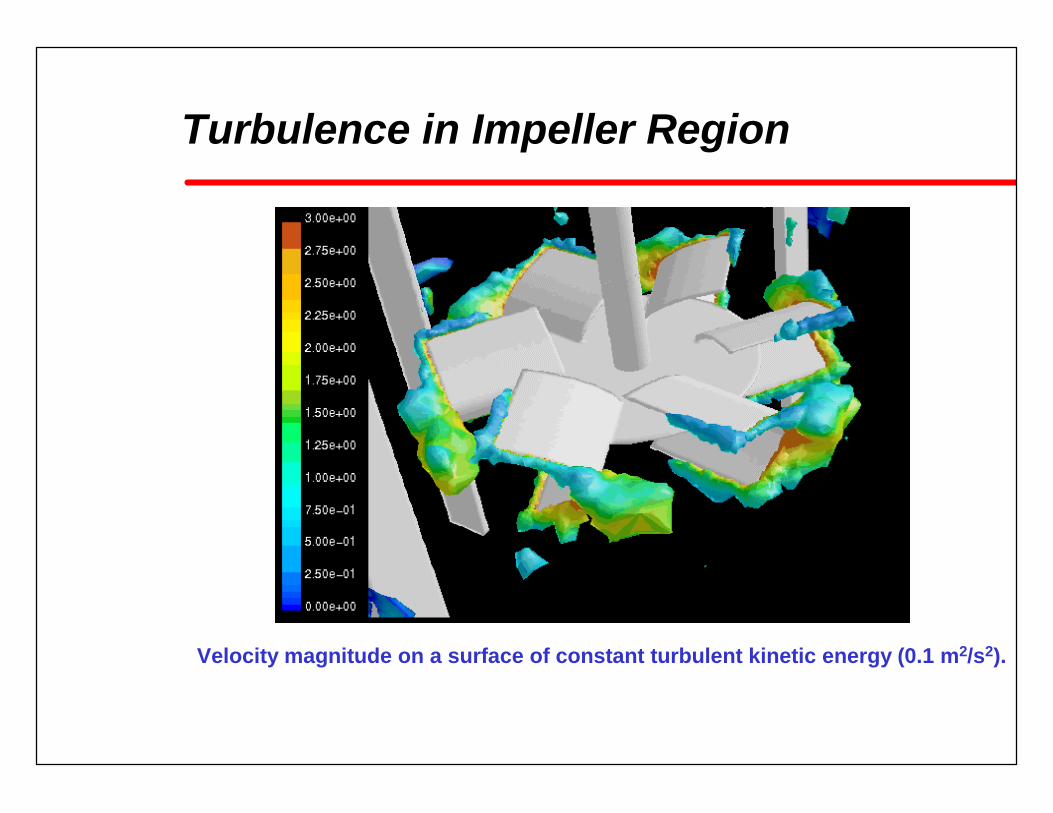
Turbulence in Impeller Region
Velocity magnitude on a surface of constant turbulent kinetic energy (0.1 m2/s2).

Vorticity Magnitude
Vorticity magnitude on the impeller, tank wall, and baffles.

Ungassed Power Number Comparison

Gas Dispersion Retrofit Comparison
Rushton CD-6 BT-6
Gas flow rate 13 vvm (vsg=0.1m/s).

Gassed Power Draw Comparison

Comparison With Up-Pumping Hydrofoil
APV-B2 up-pumping wide blade hydrofoil data from:Hari-Prajitno et al., CJChE, December 1998

BT-6/Maxflo Multiple Impeller Systems
Froude Number = 0.3; D = down pumping; U = up pumping; equal power split)

Torque Required for Complete Dispersion

Power Required for Complete Dispersion

1.0 2.4 3.2 5.4
Relative Gas Dispersion Capability
0
1
2
3
4
5
6
Rushton CD-6 PD-6 BT-6
Retrofit comparison. Average of all available data.The PD-6 is a concave blade impeller with deep symmetric blades.

0
0.5
1
1.5
2
2.5
3
3.5
4
Rushton CD-6 PD-6 BT-6 1.0 1.7 2.1 3.7
Relative Gas Dispersion Capability
Constant D/T comparison. Average of all available data.The PD-6 is a concave blade impeller with deep symmetric blades.

Mass Transfer Coefficient
0
0.05
0.1
0.15
0.2
0.25
0.3 M
ass
Tran
sfer
Coe
ffici
ent (
1/s)
0 0.02 0.04 0.06 0.08 0.1 Superficial Gas Velocity (m/s)
BT-6
CD-6
D-6
Retrofit comparison.kla at Pu/V = 2.2 kW/m3

BT-6 Installation Examples
u Numerous successful industrial installations:Ø BT-6 with down-pumping HE-3 impellers in 750 kW
(1000HP) fermenters.Ø BT-6 with up-pumping Maxflo-Y impellers in 162 kW (215HP)
fermenters.Ø Multiple BT-6 impeller systems in gassed staged columns.Ø BT-6/PBT combinations in hydrogenators.
Maxflo-Y BT-6

Conclusion
u The Chemineer BT-6 is the latest innovation inradial flow gas dispersion impeller technology.
u Experimental data was gathered with high gasflow rates in tanks with diameters up to 1.53m:Ø The patented impeller disperses more gas than all other
designs.Ø The effect of gas flow rate on power draw is reduced
compared to all preceding designs.
u The flow pattern was studied in detail using theFLUENT 5 unstructured CFD solver.
u Currently, installations range up to 750kW(1000HP).