a new digital low-level rf control system for cyclotrons
TRANSCRIPT

A New Digital Low-Level RF Control System for Cyclotrons
William Duckitt

Outline• Overview of RF and Cyclotron systems
at iThemba LABS• Overview of previous RF Control
Systems• Methodology of design • Detailed description of the New RF
Control System

RF and Cyclotron Systems • 2 injector Cyclotrons • K=8 SPC1 with an
internal ion source • K=8 SPC2 with an
external ion source • K=200 SSC• Various buncher systems• In total 13 RF systems• Fixed and variable
frequency systems• Wide frequency range
from 8 to 81 MHz• Wide power range from
50 W to 150 KW
SSC
SPC1 SPC2
3

Previous Control System Block Diagram
• Primarily analogue control system• Dated, utilizes 30 year old technology• PROF180 processor with bubble
memory• Terminal display interface• Software interface upgrade but it
runs on OS2• All the terminals have failed and have
been replaced with software emulators
4
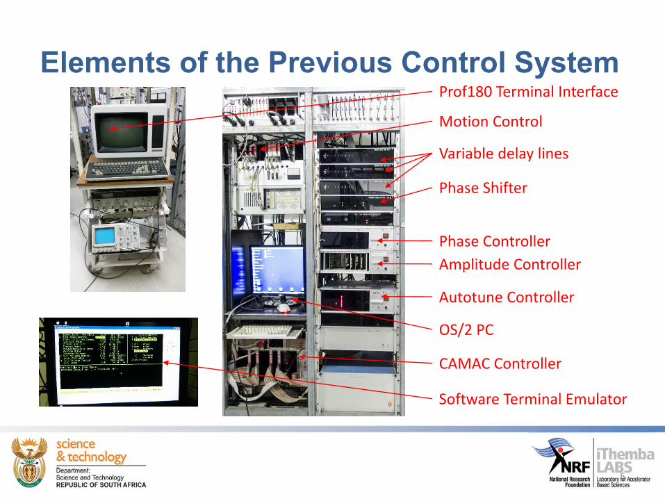
Elements of the Previous Control System
Variable delay lines
Phase Shifter
Autotune Controller
Amplitude Controller
Phase Controller
CAMAC Controller
OS/2 PC
Software Terminal Emulator
Prof180 Terminal Interface
Motion Control
5

Methodology of Design• Goal: to replace 30 year old analog control system with a generic
digital low-level RF control system over frequency range 5 to100MHz
• Performed an extensive market analysis• Several advances in technology demonstrated that it is possible
to design a DLLRF• FPGA based system is an excellent platform for design as we
can implement state-of-the-art techniques such as Direct DigitalSynthesis and I/Q Demodulation
• Set out to achieve 0.01% Amplitude and 0.01° Phase stability• Along the way it became clear there were several important
design decisions to make
6
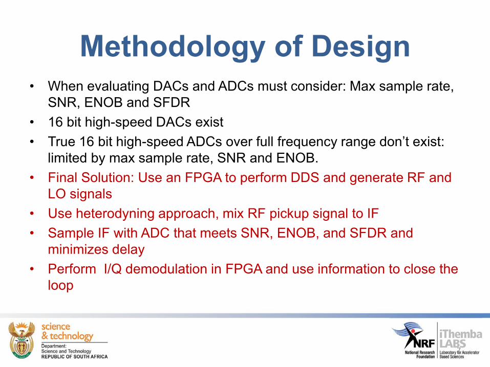
Methodology of Design• When evaluating DACs and ADCs must consider: Max sample rate,
SNR, ENOB and SFDR• 16 bit high-speed DACs exist• True 16 bit high-speed ADCs over full frequency range don’t exist:
limited by max sample rate, SNR and ENOB. • Final Solution: Use an FPGA to perform DDS and generate RF and
LO signals• Use heterodyning approach, mix RF pickup signal to IF • Sample IF with ADC that meets SNR, ENOB, and SFDR and
minimizes delay• Perform I/Q demodulation in FPGA and use information to close the
loop
7

New Digital Low-Level RF Control System• Modular Design• All RF signals are
easily accessible from the front
• Digitally programmable
• 16 bit Amplitude resolution
• Operates between 5 and 100 MHz
• Programmable in steps of 1 µHz
• Phase resolution in steps of 0.0001º
• EPICS based

Designed for Maintainability• All system modules
are easily removed• N-Type connectors to
RF systems• All RF signals are
easily accessible from the front
• Power supplies are easily accessible from the rear
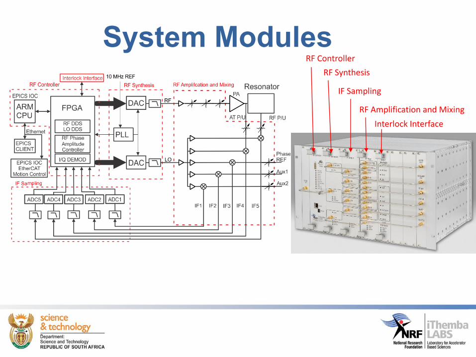
System ModulesRF Controller
RF Synthesis
IF Sampling
RF Amplification and Mixing
Interlock Interface

RF ControllerFPGA
800 MHz ARM CPUEthernet
BackplaneInterface

RF SynthesisRF Output
High-Speed DAC
LO Output
100 MHz LPF
10 MHz Ref
2.4 GHz VCO and PLL

RF Amplification and MixingRF OutputRF input Amplifier
Step Attenuators
LO input 5 Ch. SplitterBuffer Amplifier
Buffer Amplifier
Mixer
Step Attenuator
IF OutputRF Input
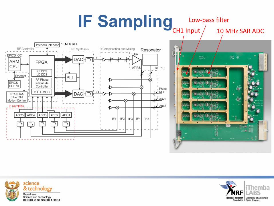
Low-pass filter
10 MHz SAR ADCCH1 InputIF Sampling

Interlock Interface4 Outputs
8 Inputs

RF Motion Control• Needed a solution for
control of the physical motion of the tuneable elements
• We could have done it in house
• However this is time consuming and requires specialised manpower
• Could we do it with off-the-shelf systems?
16

Solution• Beckhoff EtherCAT Terminals• Real-time industrial solution, available for 25 years• 1,000 distributed I/Os in 30 µs• Built on EPICS EtherCAT interface developed by Diamond Light
Source• Fully integrated stepper motor controller, DC motor controller, analog
input and output, and digital input and output terminals
17

Block Diagram Motion Control
18

Complete Solution
&
BeckhoffiThemba LABS
RF ControlPower amplifier, anode,
grid, trimmer, coupling capacitorand short circuit plate control
19

Operator User interface• Allows operator to set RF
amplitude and phase setpoints• Real-time display of 10ms and
up to 100s of RF amplitude and phase information
• All RF system interlocks are displayed
20

Engineering Control Parameters• Multi-tabbed
user interface• Adjust kick and
ramp profiles• Signal chains are
modelled schematically
• Set values of attenuators transmit and receive chain
• Adjust the PID parameters
21
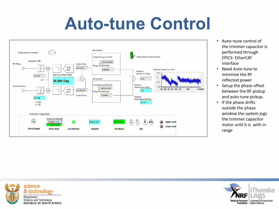
Auto-tune Control
Trimmer Capacitor
• Auto–tune control of the trimmer capacitor is performed through EPICS- EtherCATinterface
• Need Auto-tune to minimize the RF reflected power
• Setup the phase offset between the RF pickup and auto-tune pickup.
• If the phase drifts outside the phase window the system jogs the trimmer capacitor motor until it is with in range
22

Automatic Sequence Control• An SNL Sequencer program was used to
automate the system• Can operate in manual/automatic
configuration mode• In manual config , the user can adjust
parameters, find resonance and switch on the system manually
• In automatic config, the system can perform a power on reset, find resonance, and resume from cold or warm start state.
RF pickup amplitude vs encoder position during a search for resonance
23

Operational HistoryDate Frequency [MHz] Power [KW] Particle Energy [MeV]
1 2015/02/06 13.312675 4.4 40 Ar 7+ 175
2 2015/02/13 26.000000 21.3 H+ 200
3 2015/02/20 26.000000 21.3 H+ 200
4 2015/02/27 26.000000 21.3 H+ 200
5 2015/03/05 12.083549 2.8 40 Ar 6+ 144
6 2015/03/06 12.083549 2.8 40 Ar 6+ 144
7 2015/03/13 14.468056 3.7 4 He 2+ 200
8 2015/03/20 14.468056 3.7 4 He 2+ 200
9 2015/03/21 14.468056 3.7 4 He 2+ 200
10 2015/03/27 14.468056 3.7 4 He 2+ 200
11 2015/04/03 14.468056 3.7 4 He 2+ 200
12 2015/04/10 14.468056 3.7 4 He 2+ 200
13 2015/04/17 14.468056 3.7 4 He 2+ 200
14 2015/04/24 11.896349 3.5 86 Kr 12+ 300
15 2015/05/01 11.896349 3.5 86 Kr 12+ 300
16 2015/05/08 11.896349 3.5 86 Kr 12+ 300
17 2015/05/15 14.468056 3.7 4 He 2+ 200
18 2015/05/22 15.376543 5 14 N 3+ 82
19 2015/05/29 15.322345 6.3 16 O 3+ 93
20 2015/06/05 14.568634 5 16 O 3+ 84
21 2015/06/12 14.221051 3.1 22 Ne 5+ 110
22 2015/06/26 26.000000 21.3 H+ 200
23 2015/07/03 14.468056 3.7 4 He 2+ 200
24 2015/07/10 25.962188 16.2 4 He 2+ 68
25 2015/07/17 25.398046 14.9 4 He 2+ 65
26 2015/09/04 11.379999 4.2 4 He 2+ 120
27 2015/09/11 11.379999 4.2 4 He 2+ 120
28 2015/09/25 13.740135 3.1 18 O 4+ 84
29 2015/11/06 12.080335 2.3 20 Ne 4+ 72
30 2015/11/13 25.655769 9 3 He 2+ 50
31 2015/11/20 26.000645 8.8 3 He 1+ 51.4
32 2015/11/27 26.000000 21.3 H+ 200
33 2016/02/05 13.821065 3 18 O 4+ 85
34 2016/02/12 13.821065 3 18 O 4+ 85
• 3 prototypes
• Commissioned on SPC2 November 2014
• 52 energy changes in 2015/2016
• No callouts
• No breakdowns
Date Frequency [MHz] Power [KW] Particle Energy [MeV]
35 2016/02/19 24.024688 9.6 4 He 2+ 58
36 2016/02/26 24.819700 10.7 4 He 2+ 62
37 2016/03/04 24.819700 10.7 4 He 2+ 62
38 2016/03/18 11.701959 2.9 40 Ar 6+ 135
39 2016/03/24 12.285665 2.1 36 Ar 7+ 134
40 2016/03/31 12.285665 2.1 36 Ar 7+ 134
41 2016/04/14 12.285665 2.1 36 Ar 7+ 134
42 2016/04/21 12.285665 2.1 36 Ar 7+ 134
43 2016/04/28 12.228267 3.0 32 S 5+ 118
44 2016/05/05 12.228267 3.0 32 S 5+ 118
45 2016/05/13 25.962180 16.6 4 He 2+ 68
46 2016/05/20 25.999920 17.9 H+ 200
47 2016/05/27 19.664119 4.4 H+ 100
48 2016/06/01 19.664119 4.4 H+ 100
49 2016/06/08 19.664119 4.5 H+ 100
50 2016/06/17 25.655769 8.8 3 He 2+ 50
51 2016/06/30 25.655769 9.0 3 He 2+ 50
52 2016/07/08 25.655769 9.3 3 He 2+ 50
24

Comparison of Old and New system
-500 -400 -300 -200 -100 0 100 200 300 400 500-120
-110
-100-94-90-84-79
-70
-60
-50
-40
-30
-20
-10
0
Am
plitu
de [d
B]
f- fc [Hz]
Normalized Magnitude Spectrum Comparison fc= 12.228267MHz
New Control SystemOld Control System
Old New
fc 12.228267 MHz 12.228267 MHz
Power 2.6 kW 2.6 kW
SFDR 30 dB 84 dB below 150 Hz, 79 dB above 150 Hz
Amplitude and Phase Read Back of New System, Fs=2.5kHz
Amplitude Reference Setpoint: 14406
Phase Setpoint: 0 °
25

Best Performance
-250 -200 -150 -100 -50 0 50 100 150 200 250
-120
-110
-100
-90
-80
-70-63-58-50-44-40
-30
-20
-10
0
Am
plitu
de [d
B]
f- fc [Hz]
Normalized Magnitude Spectrum Comparison fc=26 MHz
Closed LoopOpen Loop
fc 26 MHz
Power 12 kW
Open-loop SFDR 58 dB
Closed-loop SFDR > 80 dB
Closed-loop Amplitude Stability Better than 0.01%
Closed-loop Phase Stability Better than 0.01 °
Amplitude and Phase Read Back of New System, Fs=2.5kHz
Amplitude Reference Setpoint: 20000
Phase Setpoint: 0 °
26

Final Production• Manufactured 35
systems• Completely
assembled 10 systems
• Enough spare parts
• Enough systems to meet existing collaboration commitments
27

Conclusion• Successfully designed a generic DLLRF control system• Can achieve RF amplitude and phase stability of better than 0.01%
and 0.01° respectively• Operational reliability has been demonstrated• Manufacturability and reproducibility has also been demonstrated• Incorporation of EPICS EtherCAT-based motion control enables the
system to be easily deployed at other facilities
28

Thank you
29