a new coring technology to quantify hydrocarbon content and
TRANSCRIPT

Pressure Coring, A New Tool for Unconventional Oil & Gas
Characterization
Matt BjorumGlobal Product Line Manager
Outline
• Technology Overview
• Coring Configurations
• Tool Overview
• Surface Handling and Data Acquisition
• Obtainable Deliverables
• Sampling Strategy Example

Gas & Fluid Analysis Sources
• Pressure Core
• Wireline Core
• Conventional Core
• Sidewall Cores
• Drill Cuttings
Uncertainty
Quality of Data

QuickCapture
Overview
• Captures all expelled gas and fluids from the core
• 3” (76mm) Diameter Core in 7‐7/8” (200mm) hole size “Wireline”
• 3” (76mm) Diameter Core in 6‐1/8” (155mm) hole size “Conventional”
• 4” (102mm) Diameter Core in 8‐1/2” (216mm) hole Size “Conventional”
• Standard 10’ (3m) in length runs
• Length can be increased or decreased depending on formation
• Pressure & Temperature Transducers
• Crack Valves Set to Control Pressure Communications
• “SAFER” work environment (Pressure Relief Valves)
• Proprietary sealing system (under patent)

Coring Configurations
Conventional/Wireline Core Runs
Pressure Core Runs
‐ 90’
‐ 10’
‐ 90’
‐ 90’
‐ 90’
‐ 10’
‐ 10’
Wireline Platform
• Alternate Between QuickCore and QuickCapture • No Tripping Required • Drill Ahead Capabilities• Suited for Longer Core Intervals
Conventional Platform
• Ability to Use Rigs Drill String• Limited Kit to Mobilize• Suited for Shorter Coring Intervals or Long Drill Breaks

QuickCapture Assembly
Bit / ShankLatch
Valve and Activator
Core Catcher
Spearhead / Inner Barrel Head
Pressure Canister
Inner Barrel
Pressure/TemperatureRecording Module
Pressure/TemperatureRecording Module
Canister

Standard Tool Set‐Up
Crack Valve
Settings
250 psi50 psi50 psi500 psi
Pressure Relief Valve Setting
• Number of Canisters • Pressure Relief Settings
• Operating (500psi)• Barrel & Canister Pressure Relief (1000psi)• Burst Pressure (5000psi)• Canisters can be Added on Surface for Safety
Crack Valve Settings Can be Adjusted

Temperature is Recorded
Stopped to Relieve Torque in Wireline
Stopped to Relieve Torque in Wireline
Pressure Steps Occur as Barrel Vents Into Canister
Core Begins to Build and Maintain Pressure
Pressure Inside and Outside Barrel are Equal
Wireline Trip‐Out Example Blue – Barrel PressurePink – Canister 1 PressureRed – Barrel Temperature

Tool Download
Pressure and Temperature Data
Core Barrel Gas Recovery (if present)
Data Acquisition:• Pressure and Temperature Data• Total Gas Volumes Measured • Gas Composition & Isotope Samples Collected• Fluid Collection
Core Barrel & Canister Recovery
On‐site Laboratory

Surface Handling
Barrel Communicating with Canisters
Tool Removed From Hole
Barrel Temp is Monitored in On‐Site Lab
Canisters Removed / Barrel Transferred to
On‐Site Lab
Barrel Continues to Build Pressure in Lab
Gas from Barrel is Transferred
to First Evacuated Cylinder
Barrel is Monitored as Pressure Stabilizes
Gas from Barrel is Transferred to Second Evacuated Cylinder
Gas and Liquids are Transferred from Canister to Evacuated Cylinder
Tool in On‐Site LabTool at Surface
Blue – Barrel PressurePink – Canister 1 PressureRed – Barrel Temperature

Core Extrusion
Core Transport Barrels
Core Transferred
Transferred To Laboratory
Slotted or Perforated Liner
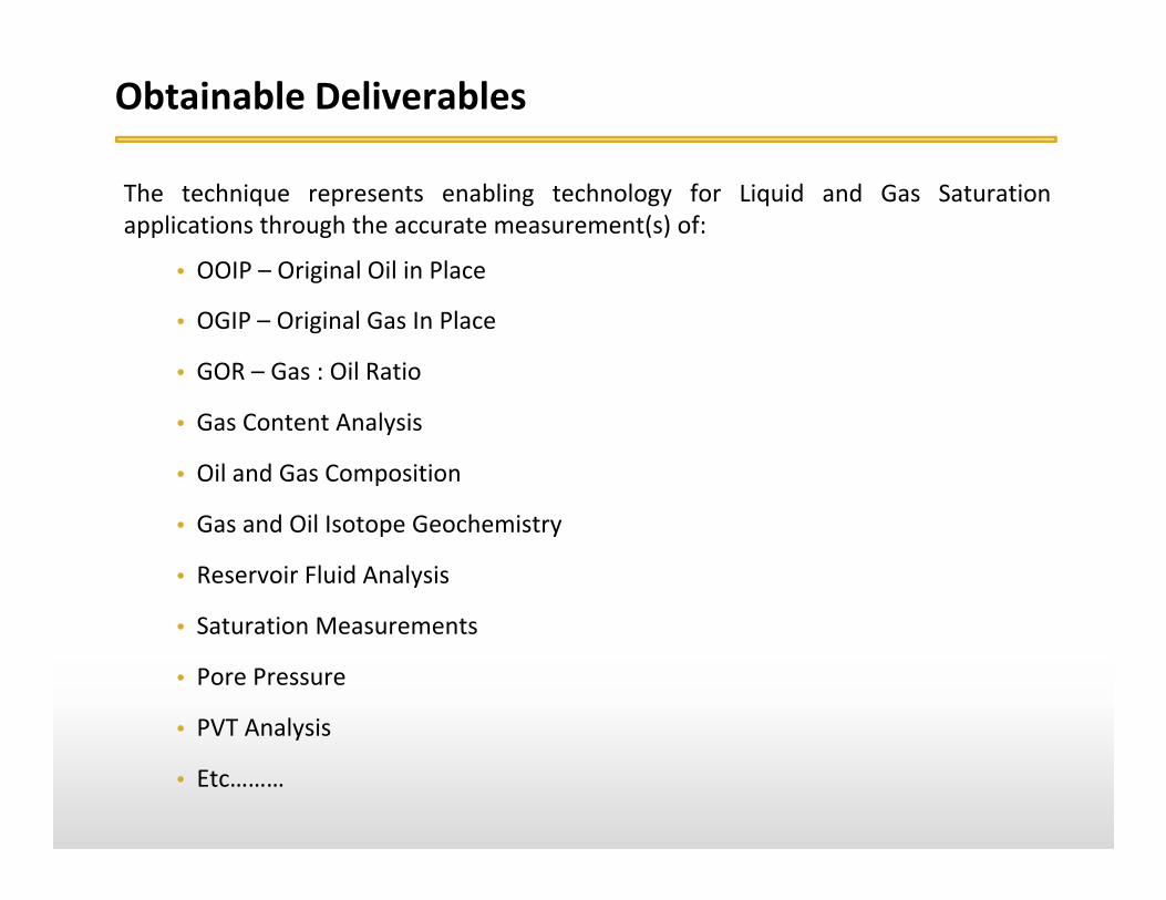
Obtainable Deliverables
The technique represents enabling technology for Liquid and Gas Saturationapplications through the accurate measurement(s) of:
• OOIP – Original Oil in Place
• OGIP – Original Gas In Place
• GOR – Gas : Oil Ratio
• Gas Content Analysis
• Oil and Gas Composition
• Gas and Oil Isotope Geochemistry
• Reservoir Fluid Analysis
• Saturation Measurements
• Pore Pressure
• PVT Analysis
• Etc………

Traditional Gas Content & Composition Analysis
-30
-10
10
30
50
70
90
0 10 20 30 40 50Elapsed Time, hours
Gas
Con
tent
, scf
/ton
Desorption Terminated; Sample is Pulverized and Residual Gas is Measured
Gas Composition Analysis
Lost Gas; Calculated
Measured Gas
Measured Gas
• Method to provide a measurement of all free, adsorbed, and absorbed gas
• Rates of gas evolution from the core matrix provide an indication of relative diffusivity
• Lost Gas is Calculated
• Evolved gas is collected to be assessed for composition and fractionation with time

Recent Gas Content Analysis Project
CanisterGas
Volume
CanisterGas
Content
LostGas
Volume
ResidualGas
Volume= + +
Calculated Measured Measured
Traditional Method
CanisterGas
Volume
CanisterGas
Content
LostGas
Volume
ResidualGas
Volume= + +
Measured Measured
Pressure Coring
All Expelled Gases and Fluids can be Analysed

Sampling Strategy Approach – Dry Gas
Feet Wireline Core1
2
3
4
5
6 P7 C8
9
10
11
12
13 P14 C GC15
16
17
18
19
20
21 P22 C23 P24 C GC25 P26 C27 P28 C GC29 P30 C
Feet Wireline Core 1
2
3
4
5
6 P7 C8
9
10 P11 C12
13 P14 C GC15
16
17
18
19
20 P21 C P22 C23 P24 C GC
25 P26 C27 P28 C GC29 P P30 C C
UPPER ZONE LOWER ZONE
QuickCapture Analysis Sampling Program
Gas Composition / Isotope Samples Collected (QC Barrel)
Gas Composition / Isotope Samples Collected (10’ Canister)
Gas Composition / Isotope Samples Collected (Crushed Gas)
Feet Quick Capture
1
2
3 GC
4
5
6
7
8 GC
9
Whole Core Analysis Sampling Program
Gas Content Samples Collected (C)
Preservation Samples Collected (P)
Canisters Dedicated for Gas Composition / Isotope Analysis (GC)
QuickCapture Sampling

Traditional Canister Gas Totals

QuickCapture Results (Actual Gas Content)

Wellsite Gas Content Numbers
Wellsite86%
Laboratory10%
Residual4%

www.corpro‐group.com
“Summary & Questions”Matt Bjorum
Global Product Line Managermbjorum@corpro‐group.com
+1.303.881.8721
5% 5%
0%
10%
20%
30%
40%
50%
60%
70%
80%
90%
100%
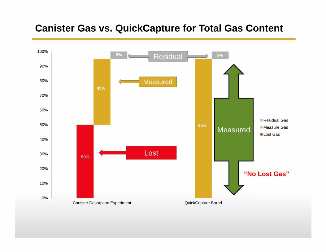
Canister Desorption Experiment QuickCapture Barrel
Residual Gas
Measure Gas
Lost Gas
95%
45%
50%
Measured
Measured
Residual
Lost
“No Lost Gas”
Canister Gas vs. QuickCapture for Total Gas Content