a new approach to manage non-traditional structural model
TRANSCRIPT

A new approach to manage non-traditional structural model geometries applied to Lubina - Montanazo field, Spain: Powered by Volume Based
Modeling algorithm in Petrel
Rosa Aguilar (1), Carlos Nuñez (2), Vanessa Villarroel (2), Marcos Victoria(1)
(1)Repsol, (2)Schlumberger

Introduction
Background
Challenges
Proposed solutions
Reservoir characterization
Faults
Horizons
Fault framework and Volume Based Modeling (VBM)
Stair-Step Gridding
Results & Conclusions
Agenda

Background
• Two oil wells producing from a fractured carbonate reservoir
• 5 km NE-SW elongated structure with rotated blocks limited by two lateral faults
• Two reservoir rocks over-imposed; sucrosic dolomites and karstified limestones
• Complex stratigraphic relationships with carbonates patches and onlaps/downlaps
• Complex fault geometries and truncations (Victoria, M: 2015)
INTRODUCTION STRUCTURAL GRIDDING RESULTS AND CONCLUSIONS
RESERVOIR CHARACTERIZATION
FAULT FRAMEWORK AND VBM

Challenges
• Represent the complex carbonate’s geology in a 3Dmodel capturing the reservoir behavior and connectivity.
• Several issues faced using Traditional Pillar gridding :
1) Too complex fault modeling process; not all the faultsincluded in the 3D grid
2) Structural and stratigraphic complexity was nothonored
3) Resulting 3D grid with a large number of distortedcells; slow simulation and convergence problems
INTRODUCTIONRESERVOIR
CHARACTERIZATIONSTRUCTURAL GRIDDING RESULTS AND
CONCLUSIONSFAULT FRAMEWORK
AND VBM

Proposed solutions
• Use the Structural Framework (SF), Volume Based Model (VBM) algorithm, and Stair-step gridding to :
Reduce the time spent on building the structural grids
Solve the stratigraphic and structural complexities
Assure to build the optimum grid to run dynamic simulations
Pillar grid faults
Structural Framework faults
Vs.
INTRODUCTIONRESERVOIR
CHARACTERIZATIONSTRUCTURAL GRIDDING RESULTS AND
CONCLUSIONSFAULT FRAMEWORK
AND VBM

Reservoir Characterization
INTRODUCTIONRESERVOIR
CHARACTERIZATIONSTRUCTURAL GRIDDING RESULTS AND
CONCLUSIONSFAULT FRAMEWORK
AND VBM
Stratigraphic & Structural Model
Initial structural configuration
Final structural configuration

Reservoir Characterization
Faults Interpretation
INTRODUCTIONRESERVOIR
CHARACTERIZATIONSTRUCTURAL GRIDDING RESULTS AND
CONCLUSIONSFAULT FRAMEWORK
AND VBM
1 Km
Fault extraction Structural Map
Structural Model

Reservoir Characterization
Horizon Interpretation
INTRODUCTIONRESERVOIR
CHARACTERIZATIONSTRUCTURAL GRIDDING RESULTS AND
CONCLUSIONSFAULT FRAMEWORK
AND VBM
1st stage
2nd stage
3rd stage
Initial Horizon configuration
Final Horizon configuration
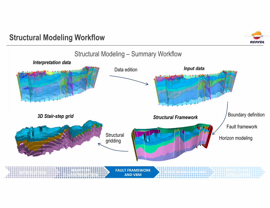
Structural Modeling Workflow
Structural Modeling – Summary Workflow
INTRODUCTIONRESERVOIR
CHARACTERIZATION
Interpretation data
Data edition
Structural Framework
Fault framework
Horizon modelingStructural gridding
3D Stair-step grid
Input data
Boundary definition
STRUCTURAL GRIDDING RESULTS AND CONCLUSIONS
FAULT FRAMEWORK AND VBM

Fault framework and VBM
Structural Modeling – Fault Framework
INTRODUCTIONRESERVOIR
CHARACTERIZATION
• Fault framework process simplifies the fault modeling
• All fault geometries and truncations easily handled
• Drastic reduction of time spent in fault modeling and editing
FAULT FRAMEWORK AND VBM
STRUCTURAL GRIDDING RESULTS AND CONCLUSIONS

Fault Framework and VBM
Structural Modeling – Input Data Preparation
INTRODUCTIONRESERVOIR
CHARACTERIZATION
Horizon Clean-up:
Clean wrong sided data to avoid incorrect modeling of horizons
Cleaning of wrong sideddata outside modelboundaries
Cleaning of wrong sideddata within modelsegments
FAULT FRAMEWORK AND VBM
STRUCTURAL GRIDDING RESULTS AND CONCLUSIONS

Fault Framework and VBM
Structural Modeling – Boundary Definition
INTRODUCTIONRESERVOIR
CHARACTERIZATION
Increase extrapolation of faults
“Watertight model”: the creation of a model with closed boundaries waskey to avoid the extrapolation of the horizons out of the faults limits.
FAULT FRAMEWORK AND VBM
STRUCTURAL GRIDDING RESULTS AND CONCLUSIONS

Fault Framework and VBM
Stratigraphic relationships
Structural Modeling – Horizon Modeling
INTRODUCTIONRESERVOIR
CHARACTERIZATION
SW NE SW NE
Base (5)
Base (4)Conformable (3) Conformable (3)
Conformable (5 NE)
Discontinuous (4 + 5 SW)
Need of combining different horizons and changing stratigraphic relationships to capture complexity
Petrel 2016 – Base-Base horizonrelationship available. No need ofcombining horizons anymore
Original Final model
FAULT FRAMEWORK AND VBM
STRUCTURAL GRIDDING RESULTS AND CONCLUSIONS

Stair-Step Gridding
INTRODUCTION STAIR-STEP GRID RESULTS AND CONCLUSIONS
RESERVOIR CHARACTERIZATION
STRUCTURAL FRAMEWORK AND VBM
Solution: Control points to constrain the horizon modeling
?

Structural gridding
• Structural gridding process generates Stair-step grids which avoid the shortcomings and limitations of thePillar grids related to complex structural relationships and cells distortion.
INTRODUCTIONRESERVOIR
CHARACTERIZATIONFAULT FRAMEWORK
AND VBMSTRUCTURAL GRIDDING RESULTS AND
CONCLUSIONS
• Stair-step grids are more suitable for simulation than traditional Pillar grids. Usually, less time is needed forreview and QC

Structural Gridding
Pillar grid Stair-Step grid
Vs.
Cell Angle property
INTRODUCTIONRESERVOIR
CHARACTERIZATIONFAULT FRAMEWORK
AND VBMSTRUCTURAL GRIDDING RESULTS AND
CONCLUSIONS
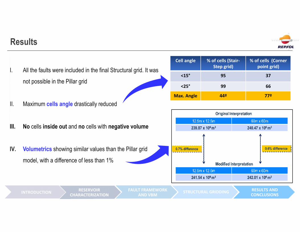
Results
I. All the faults were included in the final Structural grid. It was
not possible in the Pillar grid
II. Maximum cells angle drastically reduced
III. No cells inside out and no cells with negative volume
IV. Volumetrics showing similar values than the Pillar grid
model, with a difference of less than 1%
Cell angle % of cells (Stair-Step grid)
% of cells (Corner point grid)
<15° 95 37
<25° 99 66
Max. Angle 44º 77º
INTRODUCTIONRESERVOIR
CHARACTERIZATIONSTRUCTURAL GRIDDINGFAULT FRAMEWORK
AND VBMRESULTS AND CONCLUSIONS
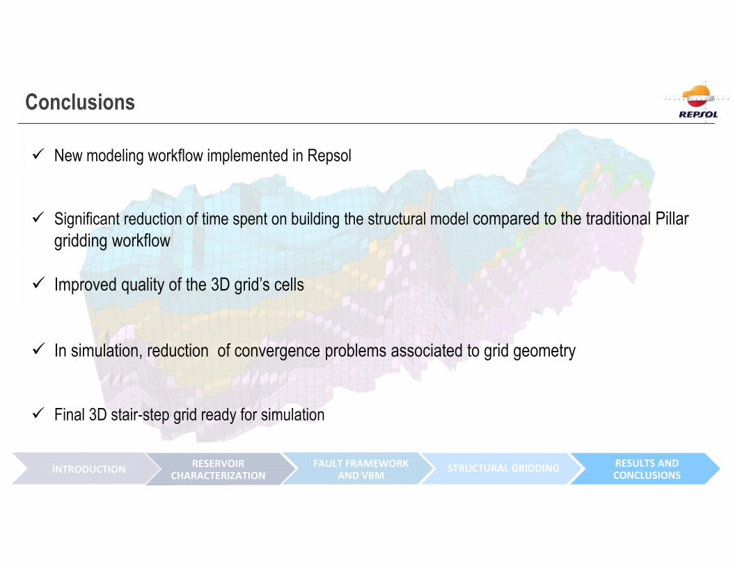
Conclusions
New modeling workflow implemented in Repsol
Significant reduction of time spent on building the structural model compared to the traditional Pillar gridding workflow
Improved quality of the 3D grid’s cells
In simulation, reduction of convergence problems associated to grid geometry
Final 3D stair-step grid ready for simulation
INTRODUCTIONRESERVOIR
CHARACTERIZATIONSTRUCTURAL GRIDDINGFAULT FRAMEWORK
AND VBMRESULTS AND CONCLUSIONS