a multipurpose software package for editing two ... · a multipurpose software package for editing...
TRANSCRIPT

Behavior Research Methods. Instruments, & Computers/990, 22 (5), 453-465
- COMPUTER TECHNOLOGY
A multipurpose software package for editingtwo-dimensional animated images
JEAN LORENCEAULaboratoire de Psychologie Experimentale
Uniuersite R. Descartes, EHESS, CNRS, Paris, France
and
REMI HUMBERTUnite Informatique Sciences Humaines
Universite R. Descartes, EHESS, CNRS, Paris, France
In this paper, we describe a software package, LEDA, for editing two-dimensional images andfilms. It is written in Turbo-C and was first conceived to work with a high-resolution graphicscard (Adage PG90/10, 2,048 x 1,023 x8 bits) on an IBM PC/AT or compatible computer. The program is intended for managing images and films used in the fields of visual psychophysics, electrophysiology, and so forth.
Software packages intended to drive currently availablegraphics displays are not always well adapted to the needsof researchers who use visual stimuli to perform a variety of experiments. Consequently, a great deal of timeis spent developing programs able to build the images orfilms needed for each experiment. It is common that, foreach series of experiments, new programs must be written, even if parts of older programs can be reused. Sometimes, a new application requires a new data structure,since old ones are too specific, and each procedure mustbe modified accordingly. This increasingly large numberof potential modifications increases the probability of bugsor program errors. Additional problems with this approach are the rapid increase in the number of programstogether with their specific graphic images, the lack ofcomments in program code, the absence of compatibility, and so forth. This scenario represents one extreme;a number of researchers and engineers, on the other hand,have developed subtle methods and modular applicationswith few of the aforementioned disadvantages.
We have developed a multipurpose program that allowsthe rapid construction of many different images and films,while taking into account the constraints of an experimental approach. Our goal. was to create software that wouldallow editing of most of the stimuli needed to performa variety of experiments in our laboratory. These includestudies on subjective contours, apparent motion withisoluminant stimuli, motion viewed through apertures,
We wish to thank Margaret Shiffrar for her comments and help inimproving an earlier draft of the text. This work was supported by GrantDRET 88/114. Correspondence should beaddressed to Jean Lorenceau,Laboratoire de Psychologie Experimentale. Universite R. Descartes,EHESS, associe au CNRS, 28 rue Serpente, Paris 75006, France.
shape recognition, and texture discrimination. The software also had to be versatile enough so that the user couldchange any parameters of interest easily and rapidly.
We wanted the program to draw images quick!y, to builda large variety of images, to be easily modifiable, andto use as little memory as possible. Moreover, we wanteda user-friendly program that anyone could use withoutprior knowledge of programming. In addition, the program had to be adaptable to different graphics displays.
In this paper, we describe the program LEDA, whichwe designed to meet the criteria outlined above. It is currently used on an AT-compatible microcomputer with amath coprocessor and a high-resolution graphics display(Adage PG90/lO, 2,048 x 1,024x8 bits). The images aredisplayed on a monitor (Sony GDM 1950) refreshed at60 Hz. To ensure maximum machine-independence, theprogram is written in Turbo-C and is distributed in different modules, each one intended for specific applications.
First, we will describe the data structure and the different modules that constitute the body of the program. Next,we will describe the different functions that are availableand how they can be used to build different kinds of images. (More details on the editing process itself areprovided in Appendix A.) Finally, we will consider somepotential extensions as well as limitations of the software.
GENERAL STRUCTURE: MODULES
To ensure easy maintenance, the program is distributedin 13modules, so that one can find, modify, or add functions that pertain to specific applications.
Four modules deal with low-level applications, such asthe management of windows, control of keyboard inputs,
453 Copyright 1990 Psychonomic Society, Inc.
454 LORENCEAU AND HUMBERT
Don 0nI I ~LJ
menus, and cursor control. They are grouped into alibrary. Four other modules manage operations on thedata. One deals with elements (e.g., allocation ofmemory), one deals with images, and two manage partsof images (block) and a complementary buffer (clipboard).Two modules are used for mathematical operations on thedata. The first one contains low-level functions such ascalculating the x- and y-coordinates of lines from theirlength and orientation, or calculating the value of a sinusoid from its amplitude, pulse, and phase. The second onecontains procedures that allow for more complex operations on the data. One module contains the functions usedto save or load images, change the directory, and so forth.The procedures used to drive the graphics card are in aseparate module, so that modifications only at this levelare needed to adapt the program to different displays. (Additional information for adapting the software is providedin Appendix B.) Finally, the main program, LEDA, organizes the links between the modules.
STRUCTURES AND DATA:IMPLEMENTATION
a
Null
First current
b
/~,
(~: i~::ent )N° column
\ N° line
~preceding element following "ement
Last
Null
number of coordlnat..
Shapecolor lengthmode angle
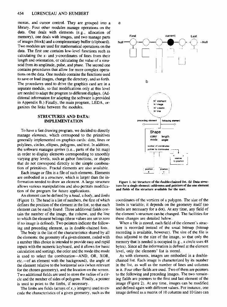
Figure 1. (a) Structure of the double-chained list. (b) Data structure for a single element: addresses and pointers of the one elementand fields of the structure available for the user.
xI relall ....: to poettlonk L-_~
POIUIo"l
~"-__ J
.....'! ccefuon I, X '
coordinates of the vertices of a polygon. The size of thelimbs is variable; it depends on the geometry itself (nolimbs are necessary for a dot). At any time, any field ofthe element's structure can be changed. The facilities forthese changes are detailed below.
When a file is stored, each field ofthe element's structure is recorded instead of the usual bitmap (bitmaprecording is available, however). The size of the file isthus adjusted to the size of the image, so that only thememory that is needed is occupied (e.g., a circle uses 48bytes). Since all the information is defined at the elementlevel, only the elements' list is stored.
As with elements, images are embodied in a doublechained list. Each image is characterized by its numberin the list, as well as the number of lines and columnsin it. Four other fields are used. Two of them are pointersto the following and preceding images. The two remaining fields are pointers to the first and last element of theimage (Figure 2). At any time, images can be modifiedand defined again with different values. For instance, oneimage defined as a matrix of 10 columns and 10 lines can
To have a fast drawing program, we decided to directlymanage elements, which correspond to the primitivesgenerally implemented on graphics cards: dots, lines orpolylines, circles, ellipses, polygons, and text. In addition,the software manages sprites (i.e., parts of the bit map)in order to display elements corresponding to smoothlyvarying gray levels, such as gabor functions, or shapesthat do not correspond directly to the simple combination of primitives. Fractal elements are also available.
Each image or film is a file of such elements. Elementsare embodied in a structure, which is larger than the information needed to draw an element. A large structureallows various manipulations and also permits modification of the program for future applications.
An element can be defined by a head, a body, and limbs(Figure I). The head is a list of numbers, the first of whichdefines the position of the element in the list, so that eachelement can be easily found. Three additional fields contain the number of the image, the column, and the lineto which the element belongs (these values are set to zeroif no image is defined). Two pointers indicate the following and preceding element, as in double-chained lists.
The body is the list of the characteristics shared by allthe elements: the geometry of a given element, coded witha number (this choice is intended to provide easy and rapidinputs with the numeric keyboard, and it allows for basiccalculation and sorting), the color and the mode (the modeis used to select the combination-AND, OR, XOR,etc.-of an element with the background), the angle ofthe element relative to the horizontal axis (when relevantfor the chosen geometry), and the location on the screen.Two additional fields are used to store the radius of a circle and the number of sides of polygons. Finally, a pointeris used to point to the limbs, if necessary.
The limbs are fields (arrays of x,y integers) used to encode the characteristics of a given geometry, such as the

EDITING TWO-DIMENSIONAL ANIMATED IMAGES 455
preceding image Image
¢=======l number of columns
following image
Figure 2. Data structure for the images. Fields for the definition of images, pointers between images,and pointers toward the elements in the list corresponding to the first and last element of one image.
be changed into 10 images defined as matrices of 10columns and I line. The modifications change the segmentation of the list and not the locations of the elementson the screen, since a particular function is used to assign positions on the screen to the elements belonging tothe same image. The various allowable manipulations aredescribed below.
Note that the images' list is not recorded on disk, sinceit is rebuilt from the elements' list when a file is loadedto memory.
In addition to images, two volatile segmentations canbe used to manipulate separate parts of the elements' list.Motifs are pieces of the elements' list defined by a starting and an ending element, independently of the actualimage contents. Blocks are parts of an image (or images)defined by the starting and ending numbers of the images,the columns, and the lines. A block allows the selectionof a subpart of an image through a film. The elementsbelonging to a block or to a motif can be copied in abuffer, moved on the screen, or erased. The elementsstored in the buffer may be inserted anywhere in the list.
A film consists of a number of images that can be displayed sequentially with a given offset delay and a giveninterstimulus interval. Several other functions, such aspanning the frame buffer or dynamic bit-plane segmentation, intended to display a film, are described below.It should be noted that a film may be used to store stimulicorresponding to a block of trials, to a moving stimulus,or to both.
PROGRAM AND FUNCTIONS
The structure of the program is depicted in Figure 3.Activity is controlled through a switching procedure
toward basic functions. When the program is entered, auser can choose from a number of functions, including:editing elements (to assign values to the different fields),saving a list of elements, loading a list, clearing the current list from memory, changing directories, or exiting.
In the edit mode, four levels are accessible: edition ofelements, edition of images, manipulation of blocks, anddisplay functions. Within each of these levels, specificfunctions are used to define, modify, or display the contents or the structure of an element's list.
In the edit mode, the status of each of the different variables that define a list is shown: the number and attributes of the current element, the number and characteristics of the current image, the total number of elementsand images, the size of the current block, and the sizeof the available memory (Figure 4). The different choicescorresponding to the current level can be selected froma menu. Submenus are displayed in windows accordingto keyboard inputs.
At the element level, one can edit a list (element by element or all at once), add, insert, copy, or erase one ormore elements, and use arrows to move within a file. (Inaddition, an element can be selected by its number andthen edited.) One can define or modify an element (a geometry) or access a specific field of this element (its color,its angle, etc.). When defined (i.e., when the geometryis specified), the current element is always displayed onthe graphics monitor, at the center of the screen if x- andy-coordinates have not been defined (they are initializedto zero), or else at the requested position. With the arrows, an element can be displaced pixel by pixel. Plusand minus signs are used to adjust the step size of displacement. An element can be rotated by an adjustableincrement around its center. A switch allows the simul-

456 LORENCEAU AND HUMBERT
List of LEDA's modules
UserINPUTS
LCU RSE
LCWIND
LMENU
LCEDIT
Hard ')\ Disk,<:>'
LEDA
LEDEL
Figure 3. Modular conception of the software package: modules for keyboard inputs and management ofwindows, management of elements, images, mathematical operations, block, and complementary buffer. Display functions are grouped in a single module, so that only modifications at this level are necessary when adapting the software to a different graphics library.
taneous presentation of several elements as one movesthrough the list, so that one can control and adjust therelative positions of different elements.
At this element level, one can copy the contents of amotif of a given size (number of elements) from a starting point to an end point. The contents of a motif, defined by its size and the number of the first element, canbe elements as a whole or a single field of elements. Forinstance, four colors assigned to four different elementsmay be defined according to a color motif that can be applied to other elements of different shapes, orientations,and so forth. In the same manner, three elements definedas a triangle, a disk, and a line may be used as a motifof three geometries copied within boundaries withoutchanging the color of the modified elements.
Mathematical functions (linear, triangle, exponential,square, gaussian, sinusoid, etc.) can be applied to modifya specific field of one part of the list and/or one type ofgeometry. For instance, one can linearly increase the sizeof all the lines between given limits of a file containingdisks and polygons. This option works in the followingmanner: for each element within the defined boundaries,a value, k, is regularly incremented and used to calculatea function whose parameters have been input at the keyboard. On request, the result of the calculus, y, canreplace, be added to, multiply with, or divide, the value
of the element's attribute to be changed. The resultingvalue is then assigned to the attribute's field.
The image level is designed to edit, move, modify, insert, or add images to the image's list. The arrow keysare used to move back and forth in the images' list; thecurrent image is always displayed on the graphics monitor. A switch permits the viewing of successive images,which are then superimposed. When the switch is on, allbut the current image are cleared.
If the number of elements in the list is not large enoughto build the desired images, additional elements are automatically allocated and initialized to zero (the "copy amotif" option can fill them in).
The structure of an image is a matrix of columns andlines. Film editing requires the definition of the numberof images together with the number of columns and lines.Images are defined one by one or all at once and can bechanged at any time.
Once the images are defined, the positions of the elements belonging to the same image can be defined. Forthis purpose, one must define the position of the first element of the image, the distance between columns, andthe distance between lines. It is also possible to use increments to modify the interelement, intercolumn, interline,and interimage intervals. This permits one to edit different types of periodic structures very rapidly (checker-

EDITING TWO-DIMENSIONAL ANIMATED IMAGES 457
\a: BRISTOL.LDAElement Image List Block: first-last
nO 1 nO 1 110 elements image 0 0Column 11 Film: column 0 0
Column 1 Line 10 110 elements line 0 0Line 1 1 images Buffer :
Pos. X 132 from nO 1 EmptyY 82 to nO 110 412840 bytes free
Rect. F. ELEMENT
side 1 25 1 Input one elementside 2 25 2 Input a listangle 0 3 Search for an element
color 15 4 Modify an element F10
mode 0 5 Erase elements6 Insert elements7 Copy one element8 Display a motifF6 Coordinates Info.F7 Copy a motifF8 9 An mation OptionsSave In tialize
ESC:ex t
(-) following/preceding menu F5 Displav
IMAGE1 Define images2 Define positions3 Position Options4 Move an image5 Erase Ima.+ Elem.6 List of images7 Search for an imageF6 Erase a motifF7 Copy a moti fF8 Function OptionsSaveInitializeESC: Exit
DISPLAY1. Display Menu2. Display images3. Display the List4. Modify the Palette5. utilities6. Define a window7. Rotate the Palette8. Rotate colorsF4 Rotate Bit-planesF5 PaningF6 Display motifO. Test Bit-Planes
ESC: Exit
BLOCK
1 Define a block2 Move a block3 Rotate a block4 Display current block5 Sort Options6 Text& Fill Buffer
ESC : Exit
Figure 4. Copy of the control screen while in the edit mode. The menus for managing images, blocks, and display functionsare also shown. Depending on the user's choice, submenus are displayed in the main window. However, information aboutthe status of the file remains visible.
board, square-wave gratings, etc.). In addition, an image can be moved in any direction with the arrow keys.(Steps of displacement are adjustable with the plus andminus keys.)
Since one often has to deal with different aperiodicstructures, facilities for the positioning of elements areprovided: One can fill in a pattern with the elements ofthe list, given the intervals x and y between elements andlines of elements. One can also copy a motif of positionswithin boundaries of the elements' list. For instance, ifthree or more elements have been placed at different locations, their relative positions can be assigned to anygroup of three or more elements. Absolute positions canbe defined by fixing the amount of displacement on thex- and y-axes relative to the copied positions.
Random noise can be applied to an image in order tomodify the positions of the elements by a random amounton the x- and y-axes separately. A similar randomizationcan be applied to each of the fields of the element's structure (color, length, etc.).
These different functions appear to be very powerfulfor building simple or complex images, simply by mov-
ing between positioning functions and image definitions.For instance, if several images are defined and positioned,a simple redefinition of these images as one single largerimage will produce a much more complex structure,which in turn can be replicated and modified. The resultwill be a film of complex images.
LEDA can also be used to edit fractal images (Mandelbrot, 1982). The construction of fractal images requiresthe choice of a number of transformations of the element'slist (see Barnsley & Sloan, 1988). Each transformationis defined by seven values, including the probability ofapplying the transformation onto the list. These transformations apply on x and y locations and are added to thecurrent positions of the elements (for that reason, all theelements should be initialized to the same location beforeconstructing a fractal image).
The block level is designed for manipulation of partsof images, such as the elements between two differentcolumns, two different lines, and two different images.A block can be moved, rotated, or erased. At this blocklevel (but also accessible from the element and the imagelevel), part of the list (i.e., a block or a motif) can be

458 LORENCEAU AND HUMBERT
copied in a buffer. The contents of the buffer can be reinserted anywhere in the list. (This function correspondsto the copy-cut-paste functions available on Macintoshcomputers, but it should be noted that LEDA deals withelements rather than bit maps).
There are different animation procedures for computers(see Proffitt & Kaiser, 1986). One can draw the differentimages sequentially, with the constraint that the time between frames depends on the time needed to write the images. Other possibilities offer faster and more flexible animation. One is to write all the images in a different partof the frame buffer. The animation is then produced bypanning the frame buffer with appropriate values in orderto present the images within a window. This method hasthe constraint that the number and the size of the imagescannot be too large. When several bit planes are separatelyaccessible on the graphics display, and few colors are displayed simultaneously, one can write each image on oneor several bit planes. Animation is obtained by showingthe selected bit planes at a chosen rate. Dynamic changesin the look-up table (LUT) have also proven to be powerful tools for animation.
The choice of one or another procedure (or their combination) depends on the required animation rates, the complexity of the images, the number of colors to be displayedsimultaneously, and/or the number of images that makea film. In apparent motion perception (Braddick, 1974;Cavanagh & Mather, 1989; Papathomas & Gorea, 1988),one often uses cyclic presentations of a reduced numberof images. This allows the use of more powerful animation procedures (i.e., the faster rates).
In LEDA, the film level includes display functions andseveral other useful functions, such as the edition of colors(i.e., changes of the LUT), zooming, panning, testing ofbit planes, and so forth.
The display menu permits one to look at a film-severalimages-at a chosen rate, with or without an interimageinterval. The images are displayed one by one in sequence.This menu allows a control of what should appear duringan experiment, although the rate is not optimized, sinceinformation, printed on the control screen, is timeconsuming (moreover, the rate depends on the numberand type ofthe elements within an image; filled elementsare drawn more slowly than outlined elements).
LEDA also provides a cyclic display of the bit planes(on an 8-bit graphics card, each bit plane can be accessedseparately for read or write operations). One can defineone, two, four, or eight planes to produce the desired segmentation of the eight available bit planes. Animation isrealized by cyclic presentation of the selected bit planeswith an adjustable delay between frames. The rate of animation is then independent of the complexity of the image. Along the same lines, a cyclic modification of theLUT is available to produce high-rate animated images.Suppose, for instance, that one image corresponds to 100lines displayed side by side, but that 99 lines have the colorof the background (i.e., they are invisible). If the colorof the remaining visible line is successively assigned to
each of the lines, one will perceive an apparent motionof one single line. The rotation of the colors of the LUTavailable in the program can be realized within boundaries at a chosen rate. Moreover, different parts of theLUT can be rotated simultaneously, which allows different animation rates for different objects (e.g., two or moregratings can drift in different directions at different rates).
The LUT available with 8-bit planes has 256 entries(i.e., 256 colors can be displayed simultaneously). Eachcolor is defined by the intensity of the red, green, andblue channel. LEDA proposes different predefined definitions of the LUT that can be chosen in a menu. In orderto manipulate the LUT further and thus change the colors,several functions are available. One can change each colorseparately by adjusting the red, green, or blue channel.The values of calculated functions can also be applied toeach channel separately or to the three channels at once.With these functions, it is easy to define different palettes.For instance, one can define a sinusoidal variation of theintensity of the red channel and a linear increase of the intensity of the green channel, while the intensity of the bluechannel decreases. These functions can be applied withinlimits. The LUT defmed in this way can be saved (or not),together with the images.
POTENTIAL EXTENSIONS OF LEDA
Although the current version of the software allows theconstruction of a large number of different images, severalextensions are possible. One extension under developmentis the management of a mouse for positioning or editingelements or images.
In order to run different experiments with specificmethods and procedures with the images edited withLEDA, a specific module intended for running experimentscan be added to the existing ones. We developed such amodule for running experiments in our laboratory (Gorea,Lorenceau, Bagot, & Papathomas, 1990; Lorenceau &Shiffrar, 1990). The experiment module allows the definition of the parameters and procedures that are neededfor specific animations used in experiments, together withthe definition of specific variables such as the name ofthe subject, the number of trials, and so forth. Thisstrategy is very useful for adjusting the parameters of oneexperiment; it is economical, since all the functions usedto load a film or display the elements are already written; and it is flexible, since only the experiment moduleneeds to be modified for a new experiment.
The software manages text, so LEDA can be used inresearch concerned with reading. Each element can holda letter, a word, or a sentence. The size of the letters,their color, and their position can be changed easily.Image editing could be used to display several letters,words, or sentences. The display facilities can be usedto run experiments.
Another extension concerns the synthesis of imagesfrom frequency spectra. It is possible to use the fields ofan element's structure to define frequency, intensity,
EDITING TWO-DIMENSIONAL ANIMATED IMAGES 459
phase, location, and so forth. The program can allow formanipulations (e.g., filtering) of the current spectrumbefore it is sent to a Fourier synthesis module, in order todraw images.
LEDA could also beof use in other fields of research,such as psychoacoustics. For instance, the different fieldsof an element's structure could be used to define parameters such as the frequency, intensity, and phaseof different sounds. Only the messages displayed on the controlscreenandthe outputmodule thatare actually usedto drawelementson a graphicsdisplay needbe rewritten in orderto fit the hardware specifications.
The software's limitations should also be mentioned.One is the limited number of elements and images thatcan be managed simultaneously in the current version.About 400K are available for the data (elements andimages). Extendedor expanded memory is not presentlymanaged by the software. In addition, the matrixstructureof images doesnotallowthree-dimensional manipulations.
CONCLUSION
A general multipurpose software package for editingand animating images was developed to avoid the disadvantagesthat occur when a new program mustbewrittenfor each new experiment. This approach is very powerful and saves a great deal of time. Several experimentsthathavebeenrun withthis software haverequired a minimum of additional programming, although it was sometimeseasier to write an additional specificprocedure thanit was to edit the images with the tools available. However, a new procedure is easier to write when the datastructure is already defined.
The adaptationof LEDA to different graphics displaysis ensured by its modular design, although some of thegraphics functions in the present version may not existin other systems, and some functions available on moresophisticated systems cannot be implemented in LEDA.Thus, some time may be required for the user to adaptthe program to work with different graphics displays.
Althougha versionthat runs on an AT witha single monitor is available for demonstration, the program shouldbe used with two monitors for maximum flexibility andadaptability. Appendix B contains the procedure used todisplay an elementon the screen. Procedures used to displaya motif, an image,or a filmare repetitive calls, withinlimits, to this "display element" procedure. Other modifications concern panning, zooming, writing a single coloror the whole palette, and so forth. It should benoted thatthe procedures used in LEDAare availableon mostof thegraphicscards currentlyavailable, running on an AT withMS-DOS 3.3. Adapting LEDAto run withdifferentoperating systems (e.g., UNIX) requires the change of lowlevelprocedures for management of files, directories, andso forth.
If one is interested in working with LEDA, the program anddocumentation are available fromthe firstauthorfor $40 US. A version that runs on a PC (VGA display)will be provided for testing; the program requires anADAGE PG90/lO graphics card.
REFERENCES
BARNSLEY, M. F., & SLOAN, A. D. (1988). A better way to compressimages. Byte, I, 215-223.
BRADDlCK, O. (1974). A short range process in apparent motion. VisionResearch, 25, 839-847.
CAVANAGH, P., & MATHER, G. (1989). Motion: The long and the shortof it. Spatial Vision, 4, 103-129.
GOREA, A., LORENCEAU, J., BAGOT, J. D., & PAPATHOMAS, T. V.(1990). Color-based motionperception maybe strongerat equiluminantthan under nonequiluminant conditions. Investigative Ophthalmology& Visual Science, 31(Suppl. 2544-51), 518.
LoRENCEAU, J., & SHIFFRAR, M. (1990). Motionviewedthrough severalapertures: Non-rigid percepts. Investigative Ophthalmology & VisualScience, 3l(Suppi. 2557-61), 520.
MANDELBROT, B. (1982). The fractal geometry of nature. San Francisco: W. H. Freeman.
PAPATHOMAS, T. V., & GOREA, A. (1988). Simultaneous motion perception along multiple attributes: A new class of stimuli. BehaviorResearch Methods, Instruments, & Computers, 20, 528-536.
PROFFITI, D. R., & KAISER, M. K. (1986). The use of computergraphicsanimation in motionperceptionresearch. Behavior Research Methods,Instruments, & Computers, 18, 487-492.
APPENDIX A
To provide an example of the use of LEDA, we describe the steps needed to construct theBristol wall illusion.
l , Enter LEDA and select the "edit" mode.2. Select "Input one element":
· define a filled rectangle and its characteristics:· sides, color, mode.
3. Select "input a list":· choose "all at once" option.· choose "copy last element."· enter the number of elements.
4. Use down arrow to display next element.5. Select "modify an element" option:
· change the white color to gray.6. Select the "copy a motif" option:
· enter: the size of the motif and its starting element.: the limits for copying.
· select the element's fields to copy through the list.

460 LORENCEAU AND HUMBERT
APPENDIX A (Continued)
7. Use the right arrow to display the image menu.8. Select the "define an image" option:
, enter the number of images to define., select the "all at once" option., enter: the number of columns and lines.
9. Select the "define positions" option:, enter: X-, y-coordinates of the first element.
: the separation between columns and lines.: the step increment on the x-axis.: parameters for "alternate step's sign" option.
10. The image is displayed on the screen.II. Each step can be reselected to change colors, positions, and size or structure of images,
or to apply a functionon one field of the element's list. Animationprocedures are available.
APPENDIX B
/* set the mode for combining element *//* with the background *//* set the color of the element */dscoltgraf-rcolor);
/* ---- Procedure used to display an element on the graphic screen ---- */void ON_elem(liste_EL *grat){dsopm(graf -+mod_disp);
/* move to the center of the screen if x = Y = 0 *//* move to real x & y otherwise */
if (graf-rxposel = = 0 && graf-ryposel = = 0) dsamove(CentX, CentY);else dsamovergrat-sxposel.graf-eyposel);
/* Selection of what procedure to call *//* depending on the geometry of the element, coded by a number (0 to 15) *//* Coordinates of the element are relative to X & Y location */
switch (graf'-rgeometry){
/* undefined geometry */case 0: return;
/* Display a dot */case I: dsdott ):
return;
/* Display a line whose coordinates are stored in an array of integer */case 2: dsrmove(graf-+ar[O].x, graf-+ar[O].y); /* makes a relative move */
dsrline(graf-+ar[I].x, graf-+ar[l].y); /* draw a relative line */return;
/* Display a circle whose radius is equal to 'len' */case 3: dscrcltgraf-r len);
return;
/* Display a disk. MOPIN is the mode for filling in */case 4: dscrcl(graf-+ len); /* Display a circle */
dsrpaint(O, 0, graf-scolor, MOPIN); /* makes a relative paint */return;
/* Display an outlined rectangle relative to XY location *//* Length and height are stored in an array of integer */
case 5: dsrrct(graf-+arlO] .x, graf -+arlO] .y);return;

EDITING TWO-DIMENSIONAL ANIMATED IMAGES 461
APPENDIX B (Continued)
/* Display a filled rectangle relative to XY location *//* Length and height are stored in an array of integer */
case 6: dsrfrct(graf..... ar[O).x, graf..... ar[O).y);return;
/* Display a polyline of 'arsize' sides */case 9: dsrpll(graf..... arsize.graf..... ar);
return;
/* Display an outlined polygon regular (7) or irregular (10) *//* Makes a relative move from XY location to the first XY coordinates *//* and draws a polygon of 'arsize' sides */
case 7:case 10:dsrmove( - graf..... ar[graf..... arsize) .X, - graf..... ar[graf..... arsize) .y);
dsrplg(graf..... arsize -I .graf..... ar);return;
/* Display a filled polygon regular (8) or irregular (II) *//* Makes a relative move from XY location to the first XY coordinates *//* draws a polygon of 'arsize ' sides *//* fills in from the XY location to the border */
case 8:case II:dsrmove( - graf..... ar[graf..... arsize) .X, - graf..... ar[graf..... arsize) .y);
dsrplg(graf..... arsize -I ,graf..... ar);dsrpaint(graf..... ar[graf..... arsize]. x.graf..... ar[graf..... arsize). y.graf..... color, MOPIN);return;
/* Display an outlined ellipse defined by the ratio of X/Y and its length */case 12:dselps(graf..... ar[0). x.graf..... ar[O).y,graf..... len);
return;
/* Display a filled ellipse defined by the ratio of X/Y and its length *//* MOPIN defines the mode for painting */
case 13:dselps(graf..... ar[0).x,graf..... ar[0).y,graf..... len);dsrpaint(O, 0, graf..... color, MOPIN);return;
/* Makes a call to a procedure that display a text *//* ON _text transforms integers stored in an array into letters *//* concatenates these letters and display the string */
case 14:0N_text(graf);return;
/* Makes a call to a procedure that displays a sprite *//* wriLsprite reads an array of colors *//* draws a dot within a squared matrix */
case 15:wriLsprite(graf, graf....mod Ldisp);return;
/* Makes a call to a procedure that draws a fractal element. */case 16:0N _frac(graf); /* plots colored dots only */}
Note-The ON_elemO procedure is called each time an element is displayed on the graphicscreen. To adapt this procedure to another graphics card, one must change the calls to the graphicslibrary-for example, change dsamove(x,y) dscrcl(radius), which are used here to draw a circleto circletx.y, radius) if a VGA graphics card is to be used. Other modifications-for panning,zooming, writing the LUT, and so forth-are also needed. All these graphic functions are groupedin the same module. If only one screen is available for graphics and controls, switches betweentext and graphic modes should be inserted within the software.

462 LORENCEAU AND HUMBERT
APPENDIX C: Black and White Examples of Images Edited with LEDA
Image 1. Size in memory: 6,591 bytes. Editing process: 2min.
Image 2. Size in memory: 10,529 bytes. Editing process: 3min.

EDITING TWO-DIMENSIONAL ANIMATED IMAGES 463
Image 3. Size in memory: 63,081 bytes. Editing process: 10 min.
Image 4. Size in memory: 114,581 bytes. Editing process: 5 min.

464 LORENCEAU AND HUMBERT
Image 5. Size in memory: 80,208 bytes. Editing process: 10 min.
Image 6. Size in memory: 166,081 bytes. Editing process: 12 min.

EDITING TWO-DIMENSIONAL ANIMATED IMAGES 465
Image 7. Size in memory: 4,703 bytes. Editing process: 30 min.
(Manuscript received March 19, 1990;revision accepted for publication 1uly 30, 1990.)