a multibody formulation for helicopter structural dynamic ... · a multibody formulation for...
TRANSCRIPT

A Multibody Formulation for Helicopter Structural Dynamic Analysis
O.A. Bauchi~u Assoc. Professor
N.K. Kang Gruduate Asst.
Rensselaer Polytechnic Institute Dept. of Mech. Eng., Aero.Enx., and Mechanics
Troy, IVY
This paper presents a multibody formulation for helicopter nonlinear dynamic analysis. Cartesian coordinates are used to represent the eanfiwration of each body. This approach involves more unknown coordinates than
~ ~
arcstrictly necessary todefine theeonfigurationof thesystem; henee,eonstraint cqustionslinking the redundant coordinates are an integral part of the formulation. In classienl rotorcraft methodologies, elsstic bodies are revrescnted in a local. rotaline frame of reference which amounts to sevarntine rieid body and elastic motions. .. .. 'The appn,ach f#,II~,vcd in this "ark dupurli radieilll) tnom lhis rlu~sirul appn,:teh: tltr tulsl ,owtian c,tall elaclir bndie\ i, tlirectl) rcfcrrcrl 11, a single inrrlill frsmf.'l,hi~ xl,proarh readily ulla,vs 1 1 ~ ~ dr$plc,pm~nt of rennl,ulrr models to deal wilh arbitrarily complex multibody eonfig&ations. In this~work, finite rotati& are represented using the components of the conformal rotation vectnr, and the constraint equations are enforced via an aug- mented Lagrangian formulation. Simple numerical examples are presented to validate the formulation, and the ela~sical ground resonance problem is treated here as a multihody prohlem. Good correlation is found between analytical solutions and multibody formulations.
Introduction
he dynam~c analysis of rotorcraft systems involves several T. : : lnteractlng e las t~c components: several blades and rotors,
fuselage, and possibly wings. It is convenient to think of such rotorcraft systems as multibody elastic systems, i .e. a collection of mutuall;interacting elastic bodies. F& instance, in a conven- tional helicopter, the elastic rotor or rotors will interact with the elastic fuselage. The impact of this interaction is important to an accurate prediction of rotor loads, and essential when pre- dicting instabilities such as ground and air resonances since rig- idly mounted rotors do not exhibit such instabilities. In a tiltrotor design the elastic rotor and wings strongly interact, and the propeller whirl flutter is a well-known instability resulting from this interaction. Furthermore. possible interactions with the drive system and connecting shafts can lead to other types of instabilities.
In recent vears. a laree nurnbcr of advanced formulations have . . - been proposed for the analysis of an isolated rotor (Ref. I). In oarticular. finite element formulations now exist that can handle complex configurations involving hearingless root attachment systems, advanced planforms, sweep, and twist, as well as com-
posite materials. Extension of these methodologies to the mod- eling of multibody configurations presents an important chal- lenge and requires a critical assessment of existing modeling procedures.
Modeling Rigid Multibody Systems
Consider first the analysis of a system consisting of several rigid bodies. The governing equations of such a system can be derived and expressed in numerous ways, dependent mainly upon the type of coordinates selected to describe the configura- tion of the system. Three types of coordinates can be used (Ref. 2): generalized coordinates (often referred to as Lagrangian co- ordinates), relative coordinates, and Cartesian coordinates.
Figures la, b, and c represent a simplified rotor system con- sisting of a rigid shaft (height h), hinge ofiset (length r), pitch link and horn (lengths 1 and d, respectively) and a rigid blade connected to a feathering bearing. For dcmonstration purposes, the shaft is allowed to tilt in the plane of the paper, (this could reprcsent an "equivalent" bending of the shaft) resulting in a continuous change in the system's configuration.
3

4 0. A. BAUCHAU JOURNAL OF THE AMERICAN HELICOPTER SOCIETY
of the entire system. In other words, if the system's topology is modified, the basic governing equation must be rederived from
a. Generalized coordinates.
b. Relative eoordinstcs.
e. Cartesian coordinates.
Fig. 1 Representation of a simplified rotor system.
Figure la clearly shows that this system has only one degree of freedom, which can be chosen, for instance, as the tilting of the shaft b. The eauations of motion of the svstem could be obtained irom ~ a ~ i a n ~ e ' s equations with a siigle generalized (or Laeraneian) coordinate. The resultine differential eouation - for rb would be very complex, highly nonlinear, and its deriva- - . tionis by no meanstriviai. Indeed, the kinetic energy expression for the system requires, among other things, the computation of the angular velocity of the pitch link expressed in terms of $. This relationship is very complex and depends on the topology
the start, rendering the development of a general purpose com- puter code based on such coordinates very d~ificult.
Figure lb shows the same simplified rotor, but the following relative coordinates have been introduced: YI and Y2 give the angular position of the pitch link in space, and 0 the geometric pitch of the blade. Once again, Lagrangc's equations could be used to obtain the equations of motion, which consist of four differential equations for a, YI, Yz, and 0. However, three con- straints exist that link these four variables since the system has only one deeree of freedom. Hence, the c o m ~ l e t e descriotion of the.system onsis ts of four equations of mofion and thrce alge- braic constraint equations. This a ~ ~ r o a c h looks far more com- plicated than the' Lagrangian cbbrdinate approach since it involves more variables to be solved for, and more governing equations. However, some of the equations are easily derived. For instance, the angular velocity of the pitch link is computed - in terms of Yt and YZ with a simple expression involving low . levels of nonlinearities, and more importantly, this expression is indeoendent of the touoloev of the svstem. This means that a . generic expression for the kinetic energy can he derived once and for all, easing the development of general purpose computer codes.
Finally, Figure lc shows the same simplified rotor system de- scribed by Cartesian coordinates. The coordinates of the hub (x~,,y~~,zs) feathering bearing (xayb,zb) and pitch link (XI,)~,,ZI) are selected here, together with the pitching of thc blade 0. A total of 10 equations of motion could he obtained from Lagrange's equations, and clearly, nine constraint equations must link the 10 Cartesian coordinates. This apuroach yields many more . . equations and constraints than the others; however, it is well suited for the develoument of general ourpose computer codes. Indeed, a generic expression For the kindtic energ; of a rigid body whose position is defined by the coordinates of two of its points can be readily derived in terms of relationships involving low levels of nonlinearities. Most importantly, this expression does not depend on the topology of the system; thus, this ap- proach is well suited for the development of general codes deal- ing with arbitrarily complex configurations. It is clear that a proper methodology for dealing with the constraint equations is key to the success of this approach.
Modeling Elastic Multibody Systems
Consider now the analysis of a system consisting of several elastic bodies. Two approaches can be used to represent the absolute (inertial) posit~on of the deformed body. In the first approach, the displacement field is separated into a rigid body displacement field and an elastic displacement field. The rigid body motions define the position of a fictitious rigid body; thcn, the elastic motions are added to yield the true position of thc structure. This approach is a natural extension or the classical methods in rotor analysis, where the elastic motion of the blade is reoresented in a rotor-attached irame of reference.
The use of this local frame of reference eases the evaluation of the blade's total potential energy, and, furthermore, the local elastic motion can be expressed a i a superposition of prescribed modes which can be readily interpreted as flap, lead-lag and torsional motions. For small elastic displacement and rotation, the choice o r the set of orthogonal modes corresponding to the unconstrained elastic body would result in a dccoupling of the equations governing the rigid body motions and those governing the elastic motions, further easing the physical interpretation of the results. Unfortunately, this decoupling property is lost when finite elastic displacements and rotations occur as they do in helicopter rotors. In t h ~ s case, finite rotation measures must be used in the analysis.

APRIL 1993 MULTIBODY FORMULATION 5
In contrast, the evaluation of the total kinetic energy of the blade is a complex task that involves the unknown "elastic ve- locities" (i.e., the time dcrivative of the clastic displacement field), the unknown "rigid velocities," and thc corresponding coupling terms. In a finitc element formulation, the elastic de- grees of freedom at each node would be coupled with the rigid degrees of freedom, resulting in highly coupled system matrices and, hence, reduced computational efficiency. The same can be said about constraint equations between two elastic bodies which will couple the rigid body and elastic degrees of freedom of both bodies.
The second approach presents a radical departure from clas- sical rotorcraft rncthodologies: the total motion of all elastic bodies is directly referred to a single inertial frame. The total kinetic energy is now easily evaluated, as the time derivative of the displacement field readily yields the total inertial velocity (Refs. 3 and 4). However, the evaluation of the strain energy of an elastic body must be orooerlv formulated to allow finite dis- placements a i d rotation;. 1 i the finite element method is used to reoresent the elastic bodies, beam and d a t e elements must be formulated that allow finite displacements and rotations and pre- sent the required property of invariance with respect to a rigid body motion. Clearly, the proper parameterization of the finite rotation variables is a key leature of this approach. It sho~ild be noted, however, that if the elastic motion of the body is itself large, as in the case of helicopter blades, a proper representation of the finite rotations is necessary even when the motion is rep- resented in a local frame as in the previous approach. Hence, the usefulness of local frames becomes questionable. It is clear that [nodal analysis is no longer possible with this forrnulation. In addition, the accuracy and convergence charactcristics of mo- dal mcthods applied to nonlinear rotor proble~ns are question- able (Ref. 5).
Parameterization of the Finite Rotations Finite rotations can be parameterized in a number of ways.
Euler angles are widely used in rigid body dynamics, vehicle dynamics, and helicopter rotor problems (Refs. 6 and 7). The drawbacks of this representation are numerous: singularities oc- cur for specific rotation magnitudes; the expression of the rota- t i o n mat r ix i n t e rms of E u l e r a n g l e s i s c o m p l e x and computationally expensive as it involves multiple trigonometric function evaluations; and finally, from a theoretical viewpoint, Euler angles are not closely related to the tensor representation of finite rotations.
Euler parameters are popular in rigid multibody analysis (Refs. 8-10), and have been used for rotor problems (Ref. 11). They present no singularities and their low degree of nonlinear- ity makes them very attractive in modal analysis. Their major drawback is that four parameters are subjected to a normality constraint. However, numerous methods exist to parameterize finite rotations with three parameters such as Rodrigues parame- ters (Refs. 12 and 13). the conformal rotation vector, and the rotational vector. In this work the conformal rotation vector will be used.
An arbitrary finite rotation can be viewed as single rotation of magnitude $ about a unit vector i?, and the Euler parameters (Ref. 14) for this rotation are:
Q Q e,=cos-, ei=rr, sin- i =I, 2, 3 2 2 (1)
where rri are the components of the unit vector r r . The four pa- rameters are linked by the following normality condition:
The components of the conformal rotation vector (Ref. 14) can be defined in terms of the Euler parameters as:
Figure 2 shows the behavior of a typical component of the conformal rotation vector as a function of @. Note the nearly linear relationship between ai and @ when 101 5 n, and the sin- gularity when $ reaches 2n. Limiting the range of rotation to 1 @ 1 5 n is not admissible within the framework of a formulation where rotations are measured with respect to an inertial system resulting in arbitrarily large rotations. Hence the definition of the conformal rotation vector is generalized to allow rotations of an arbitrary magnitude:
= 4u; tan + ( k - I ) , kodd : 3 where 1 @ 1 5 n and k is an integer characterizing the rotation state. This new definition is closely related to Eq. (3) in view of the following trigonometric identities:
tan -+k- = tan - , keven (: 3 (3
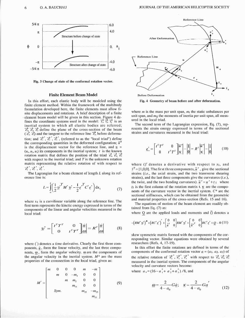
If at an instant during the motion of the elastic body the rota- tion reaches its upper bound, i.e., @ > n , one passes from the current state to a complementary one, i.e., @-> $'= @ - 2n, k-> k' = k + I , and ai = a( . The corresponding change in the com- ponents of the conformal rotation vector are:
a,! = -16aj I aZ
a,! = -16(ai -a;ao 12) I a'
a;=-16(at-a;ao/2-i;bo)la2 (6)
2 2 2 1 where a = a , + a , + a , and no = (16-a2)/8. Figure 3 shows what happens to @ and ai when a change of state is performed.
2 2 2 2 @ + e l + @ + @ = I (2) Fig. 2 Behavior of conformal rotation vector as a function of a.
I 6 0 . A. BAUCHAU JOURNAL OF THE AMERICAN HELICOPTER SOCIETY
Reference Line
Structure before change of state
Structure after change of state -514 rr -6.0
I Fig. 3 Change of state of the conformal rotation vector.
Finite Element Beam Model In this effort, each elastic body will be modeled using the
finite element method. Within the framework of the multibody formulation developed here, the finite elements must allow fi- nite displacements and rotations. A brief description of a finite
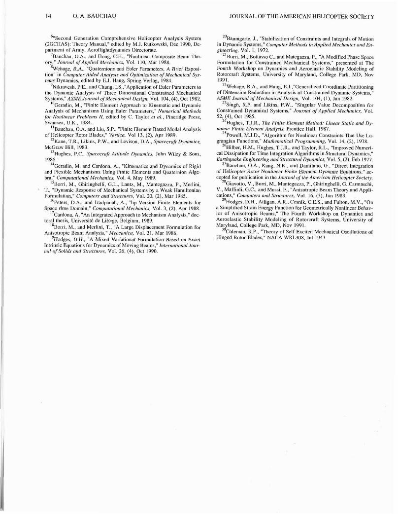
3 element beam model will be given in this section. Fi ure 4 de- fines the coordinate systems used in the model: ~ i ! is an inertial system to which all elastic bodies are referred; 2,2,2 define the plane of the cross-sect~on of the beam (2.1, and the tangent to the reference line 2 , before deforma-
tion; and 2'. 2'. 2'. (referred to as the "local triad") define the corresponding quantities in the deformed configuration; i? is the displacement vector for the reference line, and u = ( r c , , u,, a,) its components in the inertial system; t is the known rotation matrix that defines the position of the triad $,$, 2 with respect to the inertial triad; and T is the unknown rotation matrix representing the relative rotation of with respect to
2.,2*,2.. The Lagrangian for a beam element of length L along its ref-
I erence line is:
where X I is a curvilinear variable along the reference line. The first term represents the kinetic energy expressed in terms of the components of the linear and angular velocities measured in the local triad:
where (') denotes a time derivative. Clearly the first three com- ponents, i , form the linear velocity, and the last three compo- nents, g , form the angular velocity. g a r e the components of the angular velocity in the inertial system. M* are the mass properties of the crosssection in the local triad, given as:
Berare Defom.,inn
Fig. 4 Geometry of beam before and after deformation.
wherc nr is the mass per unit span, rn; the static unbalances per unit span, and 1110 the moments of inertia per unit span, all meas- ured in the local triad.
The second term of the Lagrangian expression, Eq. (7). rep- resents the strain energy expressed in terms of the sectional strains and curvatures measured in the local triad:
where ()' denotes a de r iva t ive with respect to X I , and I T = [l,O,O].Thefirst threecomponents,ij ' , give the sectional -
strains (i.e., the axial strain, and the two transverse shearing strains), and the last three components give the curvatures ( i .e . ) , the twist, and the two bending curvatures). i j ' = g ' + ~ , where tr is the first column of the rotation matrix t. 5 are the compo- nents of the curvature vector in the inertial system. C* are the sectional stiffnesses, which can be obtained from the geometric and material properties of the cross-section (Refs. 15 and 16).
The equations of motion of the beam element arc readily ob- tained from Eq. (7) as: where Q are the applied loads and moments and 0 denotes a
-
skew symmetric matrix formed with the components of the cor- responding vector. Similar equations were obtained by several researchers (Refs. 4, 17-19).
In this effort the finite rotations are defined in terms of the components of the conformal rotation vector a = (01, a2, a,?) of
the relative rotation of 2'. 3'. 2' with respect to ??,2,2 measured in the inertial system. The components of the angular velocity and curvature vectors become:
2 2 2 where a , = ( 1 6 - a , + n , + a , ) / 8 , a n d

APRIL 1993 MULTIBODY FORMULATION 7
as can he found by introducing the conformal transformation Eq. (3) into angular velocity and curvature vectors expressed in terms of Euler Parameters. The rotation matrix is then simply:
Enforcement of the Constraint Equations
We now turn our attention to the enforcement of the constraint conditions between the various elastic bodies. They introduce an "infinite stiffness" into the system and have a destabilizing effect on the time integration process. Several methodologies have been proposed to overcome this problem. One of the first such methods is the constraint violation stabilization method proposed by Baumgarte (Ref. 20). In this approach the con- straint equation linking the coordinates - q written in a generic form as
C(q) = 0 (15) is replaced by
The drawbacks of this approach are clear: the constraint condi- tion is not satisfied exactly since Eq. (16) is enforced rather than Eq. (151, and the method introduces two problem dependent parameters, a and p, that must he appropriately chosen in order to stabilize the integration process.
In the modified phase space lormulation (Ref. 21), the state vector of the svstem is described in a modified ~ h a s e suacc
classical Lagrangian multipliers is avoided in favor of a differ- ent form of multipliers which are their integrals in time. This approach requires a phase space formulation whtch might result in higher computational costs.
The coordinate partitioning method (Refs. 22 and 23) makes use of the fact that the coordinates q are not independent, and hence can be partitioned into a set cf independent coordinates and a set of dependent coordinates. The set of independent co- ordinates is deterrnincd by a matrix factorization process with full or partial pivoting. This method has two drawbacks: pivot- ing techniques are not well suited for large scale systems as they
destroy the bandedness of the matrices, and only holonomic constraints can he treated in this way.
The penalty method (Ref. 24) is also popular for enforcing constraints within the framework of variational problems. If L (q ) is the Lagrangian of the system, a penalty term is added to geld:
where p is a large penalty coefficient. The difficulties associatcd with the penalty method are that the constraint is never exactly satisfied, and the presence of a large penalty coefficient can render the system matrices ill-conditioned.
The ~ a ~ r a n ~ e Multiplier Technique (Ref. 24) is another well- known techniaue in which the Laeraneian of the svstem is modi- - fied to yield:
where h is an additional unknown called Lagrange multiplier. This powerful method enforces the constraint exactly; however, factorization of the system matrix requires full or partial pivot- ing to avoid singularities. This problem can he overcome by using the augmented Lagrangian formulation (Ref. 25):
where p is a penalty like coefficient. This term need not belarge, as in Eq. (17). and prevents the appearance oczero pivots in the factorization process, provided that the unknowns are ordered in a way such that the Lagrangian multipliers are placed after the degrees of freedom participating in the constraint.
The constraint equations are readily integrated into the finite element analysis by adding the Lagrange multiplier and penalty like terms to the Lagrangian of the system. The Lagrange mul- tipliers are treated as additional degrees of freedom added to those of the structure.
Formulation of the Constraint Equations for a Revolute Joint
Consider a revolute joint in which two components undergo a relative rotation Q, as shown in Fig. 5. The orientation of the
A two components of the joint are defined by the triads f,, and
B f,, , respectively, which are coincident before deformation, A
i.e., 7?(=f:-2,p After deformation the triad f,, has ro- *A
tated to ??,, , and the corresponding rotation matrix is R ( d . B "B
Similarly f ,, has rotated to f,, with a finite rotation matrlx R(b); a and b are confor~nal rotation vector components for the corresponding rotations, measured in the inertial system. Since a r evo lu te jo in t a l l o w s on ly a r e la t ive rota t ion abou t
*B , t h e following constraints must be enforced:
C, = 2;' . 2iA = e:~"(b)~(a)e, = 0 (2')
Fig. 5 The revolute joint.

8 0. A. BAUCHAU JOURNAL OF THE AMERICAN HELICOPTER SOCIETY
More often than not, the relative rotation 4 between the two components of the revolute joint is a quantity of primary inter- est, hot it docs not appear in the present formulation based on
*A XB Cartesian coordinates. The finite rotation from *,, to *,, can h e v iewed as a s i n g l e ro ta t ion of magni tude g a b o u t
*A 2iA = 23 , and the components r of the corresponding confor- *A
ma1 rotation vector measured in the local system *,, are given as:
where R(t) is the finitc rotation matrix defining the triad 3, in thc inertial system; a, = (16. aTBl 1 8 , bo = (16 - hTu 1 8 . The relative rotation is now:
Th!, defi11i11on <,I' lhc r c l ~ l ~ v c rotation ill tcrnn 01 lhc ri~talii~n\ nicaih C(II I I I )OIICII~ (11 the i ~ i n l cil11 lje r ~ ~ f ~ ~ r ; c d \ l i t .in addition31 constraint equation:
1 C, = 4 tan - ' -(a,bT - boaT + orb")e, - @
D (24)
Within the fratncwork of the augmented Lagrangian formula- tion, the "Lagraogian" oC a revolute joint becomes:
where 11, h2, and h3 are three unknown Lagrange multipliers. Note that a revolute joint is entirely defined by four generalized coordinates, a and 6 ; whereas in this Cartesian coordinate ap- proach it is defined by seven coordinatcs, a, h, and 0, related by the three constraints, Eqs. (20),(21) and (24). The Lagrange multipliers are additional unknowns related to the moments ap- plied on the joint, which are, perse, quantities of interest. Other kinematic constraints can be readily formulated following the scheme described in this section.
Numerical Results
The first numerical example is chosen to illustrate the use of an inertial system to represent the motion of a rotating beam. Consider a straight beam of length L = 3m, rotating at a constant angular velocity R = 98.17 radlscc. The linear density of the beam i sm = 3.29 kglm, and its bending stiffness in the flap and Icad-lag directions arc 1.28 x lo4 and 1.56 x 1OSNm2. respec- tively. The classical approach in rotorcraft dynamics is to rep- resent the motion of this beam in a coordinate system that is rotatinn with the beam. The solution of the problem is then Iriv~i.l 1111 cl:~<tir cli\pl;icr.n~r.nts will1 rcspcit tu the rotal~ng Iriild .Ire ~Jc!it~c:illy zr.ro exrcpt t l~e clung:~t~~,n (11 (he hr..1111 under tllc effect of the cen t~ i fu~a l fo rces . his contrasts with the present approach where the rotating beam is directly referred to an in- ertial system; hence the rigid body rotation is the unknown re- sponse of the beam. To assess the accuracy of the solution, the numerical results are compared with the exact solution of the problem, I$ = Rt, where 0 is the rotation of the blade. A time period of 3.2 x sec was modeled (corrcsponding to a total
rotation I$ = n rad) with 12, 18,36, 180, 360, and 720 equal time steps. The log of the relative error at the last time step defined as (g, - a) /n is plotted in Fig. 6 , where is g, the predicted rotation angle versus the log of CPU time. Two time integration schemes were used to inteerate the equations of motion: a finite
idly as the number of time steps increases. The second numerical example deals with the analysis of a
pendulum of mass ,,I = 1.0 kg, and length L = 0.5 m (see Fig. 7) (Ref. 17). The origin of the axes system is at a horizontal offset e = 0.1 m. The pendulum is started from its lower equi- librium position with an initial velocity V, = 1.5 m/s and is subjected to the acceleration of gravity g = 9.81 m/sec2. The pendulum is modeled as a point mass with two degrees of free- dom, subjected to a constraint enforcing a fixed distance L from 0 to A. The response is integrated for a period of 1 sec with time increments At = 0.005 sec. After 200 steps the predicted position of the mass is within 0.02 percent of the analytical solution. Figures Xa and 8b show the time history of the hori- zontal acceleration of the mass. The HHT integration scheme was used with various amounts of numerical damping a = 0, -0.05, -0.1, and -0.3. For a = 0 the integration scheme presents no numerical damping, and as a result, the acceleration oscil- lates at each time step about the exact solution. The amplitude of this oscillation increases and would eventually lead to an instability. Figure 8b shows that a small amount of damping is sufficient to control these oscillations, which have almost dis- appeared for a = -0.1 or -0.3. Distinguishing between spurious (or numerical) oscillations and possible physical instabilities could become a problem. The frequency of the oscillations is probably a good indicator: very high frequencies (of the order
I&-. I;-. lh ld CP" (hours)
Fig. 6 Relative errors versus CPU time for the FET and HHT approaches.
Fig. 7 The pendulum problem.

MULTIBODY FORMULATION 9
- 6 - 1
e ~ o o 0.z- 0.30 0.7s t.00 Time (oecs)
9
g =- = E
3 2
2 s. 3 z C s =-
Fig. 8a. Time history of horizontal accelerations with a = 0.0 and -0.05.
.................... HHT ol= 0 . ~ 0 ~ ~ . ~ .~ HHT a=-0.05
Fig. 8b. Time history of horizontal accelerations with a = - 0.0 and -0.03.
of the time step) are probably of numerical origin, whereas low frequencies are more likely to be of a physical nature.
The third numerical example deals with the rigid, two-body problem shown in Fig. 9. Bar 1 (length 11 = 0.5 m, mass ml = 1.6 kg) is frec to rotate about the origin but restricted to the xy plane. This constraint is enforced by a revolute joint which al- lows rotation only about the z axis. Bar 2 (length 12 = 0.5 m, mass szz = 1.6 kg) is connected to the end of bar 1 and is allowed to rotate about an axis that remains aligned with bar 1. This constraint is enforced once again by a revolute joint. The stiff- ness properties of thc bar are as follows: bending stiffness in flap and lead-lag direction of 1.28 x lo7 Nm2 and 1.56 x loR Nm2, respectively, and a torsional stiffness of 1.53 x 10⁷ ~ m l . These stllfnesses were chosen to be very high to simulate rigid bod~es. The multibody, finite element model consists of two 3-noded beam elements (onc for each bar), and two revolute
x . 0 0
4- E 3 g :.
Fig. 9 The articulated dborv.
Time (oeco)
3 g .: 0 r q.
- -
joints, for a total of 32 displacement degrees of freedom, and 6 Lagrange multipliers.
For rigid bars, an analytical solution is readily obtained in terms of the two degrees of freedom, and 91, and 82 represented in Fig. 9. The governing equations of motion are:
HHT a=-0 .1 ~~~~~~ ~~~~~ ~~~~~~~~ ~~~~ ~~~~~~
HHT o le -0 .3
1 (26a)
-D$, sin 8 , + D,e, = ~ ( t ) - -ole: sin 2 0 , (26b) 2
0.00 0.es 0.SO 0;s
ml 2 I t",,,: where D l = (T + HI,) 1 , +i c o d 02, D2 =+n2l1I2, 2 andD3 = - 3
is a time dependent force acting in t h e y direction and applied at the junction between the two bars; and T(t) is a time depcnd- ent torque acting at the second revolute joint. The initial condi-
l i o n s a r e 8 1 = 8 1 = 0 ; 9 2 = 1 & = 0 . In t h e f i r s t numer ica l 2
simulation (CaseI), theapplied loadsare:
F(t) = O.l* <t> N and T(t) = O.Ol* <t> N where <r> = r for O < t < I O s e c
= 2 0 1 for 10 < t < 20 sec (27) = 0 for t >= 20 sec
The simulation mns for 1000 time steps of At = 0.05 sec. The com- wnents of the conformal rotation vector for b a ~ 2 are deoicted in Fie. It) . whew the vcn~cal Ihnrs R . ~ I C \ C I I I il ci~:nigc ot\tilte. I:IOILI ti1i.l l i ~ u n . it i* clc;tr lh31 hdr 2 went Ihn111fih ;I t,~l:aI rol;illon \\ell in ciccr\ o i live revolutions. This representationof the rotation, which involves discon- tinuities at each chanee of state, mav look somewhat unusual. How- - ever, the same rotation can bcvisuali~ed in a numberofalternate ways. For instance, the time history of the same lotation in terns of the direction cosines of bar 2 witjl respect to the ineltial system is shown in Fix. I1 (tii are the components of the mtation mahix TI: note that all discontinlities have now disappeared. Figures 12a, b, &d c show the x, y and z positions of the center of mass of bar 2 versus time, respectively. A reference solution was obtained by integrating the equations of motion Eqs. (26) numerically using the Runge-Kulta method. The reference and numerical solutions are found to be in excellent agreement. Figure 13 shows the three components of the velocity vector of the center of m a s of bar 2. Here again excellent agreement with the reference solution is found. Figure 14 shows the second derivative of thc first component of the conformal rotation vector a] . For a = 0 growing oscillation appears, and an instability occurs at t = 22.15 sec: for a = -0.05 the instability is delayed up to t = 40.65 sec; finally, for a = 0 . 1 no instability occumd. This clearly
Time
Fig. 10 Time history of conformal rotation vector nf bar 2 for case I.

I 0 0. A. BAUCHAU JOURNAL OF THE AMERICAN HELICOFIER SOCIETY
Time
1 Fig. 11 Time history of direction cosines of bar 2 for case I.
S I 0.0 10.0 Z O ~ O Z O . 0 -0 0 SO^,
T f m e
Fig. 12a Time history of X position for case I.
n"a,"tical <ear 1 A"n,rtisel ( B s r B I1HT a=-0.1 ( B o r l l L - - - - -~-~-~. . . . . . HHT a=-0.1 JWaI=.)- - - - - - ~ ~ ~ ~ . . . ~ . ~
Fig. 12h Timc history of Y position for case I.
- - I 0 0 to 0 zo.0 30.0 ao.0 8 O . C
Time
Fig. 12e Time history of Z position for case I.
Fig. 13 Time history for linear velocity of bar 2 for case I.
demonstrates the need for high frequency numerical damping when integrating systems with kinematic constraints.
For the second numerical simulation (Case 11) no external loads wcre applied; howcver, the angular velocity of bar I is prescribed to a constant value of 0.5 radlsec. The time history of the components of the conformal rotation vector for bar 2 is shown in Fig. 15. The simulation covers six complete revolu- tions of bar 2 with 1000 time steps of At = 0.05 sec. Excellent agreement was found between the analytical solution and the numerical predictions.
The multibody formulation is not limited to the analysis of rigid bodies. In a second set of runs, the stiilnesses of the bars were set to realistic values: bending stiffness of 1.28 x LOZ ~m~ and 1.56 x 10' ~m~ for the flapping and lead-lag directions, respectively; torsional stiffness o l 1.53 x lo2 ~ m ~ . Figure 16 shows the projection of the center of mass of bar 2 in the yz inertial plane lor the rigid system (analytical solution), and lor the elastic system (finite element formulation). Elastic motions are clearly captured together with the rigid motions of the sys- tem. Elastic effects are much more pronounced when computing the torque required to spin the system at a constant angular velocity. Figurc 17 shows the time history of this torque for the rigid system (obtained from the analytical solution) and elastic system (obtained from the multibody formulation); peak torque values differ by a factor of about 4.5.
The last numerical example deals with the ground resonance or windmill problem. A four-bladed lag-hinged rotor is mounted
1 HHT a - 0 . 0
2 ' 1 , & 5 R m 9 -
0.0 10.0 zo.0 30.0 Time
R c 0 HHT a=-0.05
2 .? - - E - --1 0.0 10.0 ZO.0 Time
- s HHT a=-0 .10 .= g -. - - 8 s - -
0.0 xo.0 -0.0 zo.0 40.0 em Time
Fig. 14 Timc history of S I of bar 2 for ease I.

APRn 1993 MULTIBODY FORMULATION 11
Time
Fig. 15 Time hislory of conformal rotation vector of bar 2 case ll.
on i n elastic tower (see Fig. 18). Each blade is uniform and has a length L = 2.7 m, a mass mb = 20 kg (resulting in a static unbalance about the hinge Sb = 27 k g m , and a moment of inertia about the hinge I b = 48.6 kg.m2), and a hinge offset e = 0.3 m. Each blade is attached to the hub with a revolute joint, and a torsional spring of stiffness k+, = 14.0 N.m/rad acts at this con- nection. The massless tower has a height h = 3.6 m, a bending stiffness EIT = 1.62 x 10⁴ ~ m ~ , and a concentrated mass ma = LOO kg is located at the top of the tower (resulting in a natural frequency of the tower wr = 9.26 radlsec).
The analytical solution of this problem is well known (Ref. 30) and will not be repeated here. The governing equations are:
2 Rig id Bar
-1.0 -0.5 0.0 0.5 1.0 Y position
-1.0 -0.5 0.0 0.6 1.0
Y position
Fig. 16 The projected molions for the centcr mass of rigid and elastic hnr 2 on the YZ plane far case 11.
Rigid B a r Elastic Bar ................
2 :- 0.0 6.0 10.0 15.0
20.0 EL0 Time
Fig. 17 Time history of the required root torque for the rigid and elastic bars for rase 11.
where the total mass of the system M = nlo + 4mb; k ~ i s the equivalent stiffness of the tower and qr. is its tip displacement; ry; = R t + { c i -1)
the hub mtation; R its constant angular velocity; 0; the lag angle for blade i; and F(t) a time dependent lateral force applied at the tip of the tower. An "exact" solution of the problem can he obtained by integrat- ing the equations of motion, Eq. (28), with the Runge-Kutta scheme. using a very small (10-lo) error tolerance.
The stability of the motion can be assessed by transforming Eq. (28) into constant-coefficient equations using the mutiblade coordinate transformation. The unstable ground resonance re- gion was found to correspond to rotor speeds 1.2 < R c2.3, where R = R l o r .
The multibody finite element model of this problem consists of the following components: the tower (body 1) is modelcd with one 4-noded beam element with a l u m ~ e d mass ma at the tip; the huh (body 2) is modeled with four parabolic beam ele- ments (their bending stiffness is very high, to mimic a rigid hub); each blade (bodies 3 to 6) is modeled with a parabolic element (bending stiffness is very high to model a rigid blade); a revolute joint connects the tower to the hub and four revolute
wkdHH/@~ Fig. 18 The windmill prohlern.

12 0 . A. BAUCHAU JOURNAL OF THE AMERICAN HELICOPTER SOCIETY
8 m 0.0 6.5 1.0 i.s i.o i.5 i.0
Time
Fig. 19 Analytical and HHT respnses for the blade lag motions with R = 1.0.
joints, each with a torsional spring, connect the blades to the huh. The motion is restricted to the plane of the paper, for a total of 71 displacement degrees of freedom. The response of this system is found by integrating the equations of motion in time using the HHT scheme (a = -0.1) with a timc step At = 5 x 10.' sec in the case of R = 1.0. To excite any possible instability, a short impulsive load was applied at the tip of the tower. The loading history has a triangular shape with a peak value of 20 N at 0.005 sec, and is back to zero after 0.01 sec.
Figure 19 shows the lead lag angles of the four blades with respect to the huh for a rotor speed R = 1.0 (i.e. in the stable region). Each vertical dotted line corresponds to a complete
Time
Fig. 20 Analytical and HHT responses far the blade Isg motions with R = 2.0.
0.0 0.6 1.0 1.5 2.0 2.5 3. Time
c4
-- G -
I
Y - 4
B $2- 0 a - R 6 L 0
r X. 8 -i
Fig. 21 Analytical and HHT responses for the inplanc tower motions with = 1.0 and 2.0.
Analytical (n=1.0) ,... nne!utice~.(.C!=!??~ ....
HHT (n=l.O] -. :: 8 I I I ..!!m <!!?2:'?1-..... - - 8 I
I \ : : I , 1 ,
I ': 4 , I I f ,
/ ',, , ,-. . ; I ,--. a \ I I .
--. *. . ..-,' 8 b 8 , % 3 : : I.,' 3 ,
-\ : 3 ,
:,, ! .:
revolution of the rotor. Excellent correlation is found between the analytical solution and the multibody formulation. Figure 20 shows the same quantities for a rotor speed R = 2.0 (i.e. in the unstable region). The growing amplitude of the response is char- acteristic 01 the instability. The relative rotation at the revolute joint is clearly a quantity o r primary interest in this analysis and underscores the importance of defining this quantity within the formulation of the revolute joint (see Eq. (24)). Figure 21 shows the hub transverse motion at the same rotor speeds. It is also interesting to look at the motion ofJhe center of mass of thc rotor, which is depicted in Fig. 22 (X = 1.0 x lo4 X I L and Y = 1.0 x 10⁴ Y L are the normalized inertial coordinates of the center of mass). In the stable region the center or mass moves
Fig. 22 The prajfeled m o t i o n ~ f the rotor center of mass on the XY Plane (R = 1.0 and 2.0).

MULTIBODY FORMULATION 13
very little, whereas in the unstable region it spirals out with a raoidlv erowine amolitude. Note that this motion is that viewed . - " - .
I by an inertial observer and is readily available in this formula- tion since all motions are referred directly to the inertial system. Once again the multihody formulation is not limited to the mod- eling of rigid bodies. Figure 23 shows the lead-lag anele time response for a rotor wzh elastic blades, (chordGse lbending stiffness 2.52 x lo3 ~ m ~ ) . The elastic response shows large vibratory components corresponding to the response of the elas- tic modes.
The multibody formulation can also deal with variable speed rotors. To illustrate this capability the rotor was driven by a torque applied at the huh revolute joint, thereby increasing the rotor speed. The torque grows linearly from a zero value to To in 0.5 seconds, then remains constant at To. Two torque levels were applied, To = 2.5 and 0.5 kN-m. For the high-torque case, the rotor speed increases rapidly and passes through the unstable region quickly; no instability is observed. For the low torque case, the roto; speed increases slowly, dwelling in the unstable zone: an instability is then excited. Figure 24 shows the time histories of rotor speed and blade differential lead-lag angles.
Conclusions A multihody formulation for helicopter nonlinear structural
dynam~c analysis was implemented and validated. The model includes the following features:
1) Cartesian coordinates are used to represent the position of each body. Evcn though this approach requires more coordinates than are strictly necessary to represent the configuration of the system, it is very well suited for the dcvelopment of codes able to handle arbitrarily complex topologies.
2) The modeling of elastic bodies radically departs from classical rotorcraft methodologies in which elastic defor- mations are represented in a body-attached moving frame of refcrcnce. Indeed, in the present approach, each elastic body is referred directly to a single inertial system and no distinction is made between rigid body and elastic dis- placements.
0.0 0.6 1.0 1.6 2.0 2.5 3.0 Time
Fig. 23 Time history of blade lag matinn for the rigid and elastic blades with R = 1.1.
Torque I. ----.- - - - - - - - Torque 11.
1.0 0.5 1.0 1.5 2.0 2.5 3.0 3.5 4.0
Time
0.0 0.5 1.0 1.5 2.0 2.5 3.0 3.5 4.0 4.5 Time
Fig. 24 Rotor speed and blade differential lag angle for the two dif- ferent applied torques.
3) The components of the conformal rotation vector are used to represent the finite rotations.
4) Constraint equations are enforced using the augmented Lagrangian method.
5) The Hilber-Hughes-Taylor scheme is used to control the numerical instabilities associatcd with the time integra- tion of constrained dynamical systems.
6 ) Excellent correlation was found between the multibody formulation and analytical solution for simple rigid body problems.
Acknowledgments This research was sponsored by the Army Research Office
under grant DAAL0388C0004. Dr. Gary Anderson is the con- tract monitor.
References '~odges , D. H., "A Review of Composite Rotor Blade Modeling.'.
AIAA Jol,nral, Val 28. (3). Mar 1990. 'Nikravesh. P.E.. Conrp~rer Aided Aaalj7sis of Mecltorticol Sysretns,
Prentice Hall, 1987. 3~ondah, K., Tmaka, K., and Atluri, S.N., "An Explicit Expression
for the Tangent Stiffness of a Finitely Deformed 3D Beam and Its Use in the Analysis of Space Frames," Co,npare,s orld Srrrrcrnres, Voi 24. 1986.
'~imo, J.C. and VuQuoc, L., "A Three Dimensional Finite Strain Rod Model: Part I1 Compul.atianal Aspects," Conpsrer- Merhods in Applied Mecltnnics otrd E,rgi!teeri,tg, Vol 58, 1986.
'~auchau, O.A. and Guernsey, D., "On the Choice of Appropriate Bases for Nonlinear Dynamic Modal Analysis," accepted for publication in the Jormml of rl~e Arnericoa Helicopter Society
14 0. A. BAUCHAU JOURNAL OF THE AMERICAN HELICOFTER SOCETY
6"~ecand Generation Comprehensive Helicopter Analysis System (2GCHAS): Theory Manual," edited by M.J. Rotkowski. Dec 1990, Dc- partment of Anny, Aeroflightdynamics Directorate.
'~auchau, O.A., and Hang, C.H., "Nonlinear Composite Beam The- ory," Jorcnml of Applied Mechnnics. Val. 110, Mar 1988.
8 ~ e l ~ a g e , R.A., "Quaternions and Euler Parameters, A Brief Exposi- tion" in Co,nprrrer Aided A,8olysis and Opli,nizntion of Mecltn,ticnl Sys- le,ns Dynamics, edited by E.J. Haw, Spring Verlaa. 1984. - - -
'~ikravesh. P.E.. and chung, LS.,"Application o f ~ u l e r Parameters to the Dynamic Analysis of Three Dimensional Constrained Mechanical Systems." ASME JotcrnnlofMecltnrricnl Design, Vol. 104, (4). Oct 1982.
"Geradin, M., "Finite Element Approach to Kinematic and Dynamic Analysis of Mechanisms Using Euler Parameters," Nze,zericnl Merho& for Nonlbzenr P,oDlen~s If, edited by C. Taylor el a / . , Pineridge Press, Swansea, U.K.. 1984.
"~auchau. O.A. and Liu. S.P.. "Finite Element Based Modal Analysis of Helicopter Rotor Blades," Verrica, Vol 13, (2), Apr 1989.
" ~ a n e , T.R., Likins, P.W., and Levison, D.A.. Spacecrrrfl Dy,#o,nics, McGraw Hill. 1983.
I3 Hughes. P.C., Spacecrafl Atfilr<dc Dytyna,nies, John Wiley & Sons, 1986.
"Geradin. M. and Cardona. A.. "Kinematics and Dynamics of Rigid and Flexible Mechanisms Using Finite Elements and Quaternion Alge- bra," Con~pnrolionol Mecl~nnics. Vol. 4. May 1989.
I S Boni, M., Ghiringhelli, G.L., Lanlz, M., Mantegazza, P.. Merlini. T.. "Dynamic Response of Mechanical Systems by a Weak Hamiltonian Formulation," Contparer-s and Srracfa,rs, Vol. 20, (2), Mar 1985.
16 Peters. D.A., and Izadpanah, A.. "hp Version Finite Elements for Space rlrne Domain," Conzprrmrional Mechanics. Vol. 3, (2). Apr 1988.
I, Cardona, A, "An Integrated Approach to Mechanism Analysis." doc- toral thesis, Universite de Libge , Belgium, 1989.
l R ~ a n i . M.. and Merlini. T.. "A Large Displacement Formulation for Anisotropic Beam Analysis," Meccnrrica, Vol. 21, Mar 1986.
"~odges, D.H., "A Mixed Variational Formulation Based on Exaa Intrinsic Fquations for Dynamics of Moving Beams." Inlerrzarionnl Jonr- rznl of Solids rind Srrrtcla,r.~, Vol. 26. (4). Oct 1990.
'"aumgarte, J., "Stabilization of Constraints and Integrals of Motion in Dynamic Systems," CostpaterMerlrod in AppliedMechnrzics andE~z- gineering, Vol. 1. 1972.
' '~or r i , M., Bottasso C., and Mategazza, P., "A Modified Phase Space Formulation for Constrained Mechanical Systems," presented .at The Fourth Workshop on Dynamics and Aeroelastic Stability Modeling of Rotorcraft Systems, University of Maryland, College Park, MD. Nov lQ0l
" ~ e h a g e , R.A., and Haug, E.J.,"Generalized Coordinate Partitioning of Dimension Reduclian in Analysis of Constrained Dynamic Systems," ASME Joartml of Mecltnrzical Design, Vol. 104. (I). Jan 1982.
23 Singh, R.P. and Likins. P.W., "Singular Value Decomposition for Constrained Dynamical Systems," Joanrnl of Applied Mec/ta,~ics, Vol. 52, (41, Oct 1985.
24~ughes , T.J.R.. Tlze Fittile el en re,^^ Mell~od: Lirrenr. Slnric and Dy- namic Finire Elemertr Al~nlysis, Prentice Hall. 1987.
2s~owell. M.J.D., "Algorilhm for Nonlinear Constraints That Use La- grangian Functions." Mofhemalical Progmt?!,,!i!,g, Vol 14, (2), 1978.
26 Hilber, H.M.. Hughes, T.J.R., and Taylor. R.L.. "Improved Numeri- cal Dissipation for Time Integration Algorithms in Structural Dynamics." Enrfltqsake E,rgi?teen'ttg a,tdSm,crornl Dynamics, Vol. 5 , (2), Feb 1977.
''~auchau, O.A.. Kang, N.K.. and Damilano, G., "Direct Integration af Helicopter Rotor Nonlinear Finite Elcment Dynamic Equations," ac- cepted for publication in the Jozmznl of llle Anzericn,t Helicopfer Socie~y.
2%iavotto. V.. Bomi, M., Man1egaz.m. P., Ghiringhelli. G.,Carmaschi. V., Maffiali, G.C., and Mussi, F., "Anisotropic Beam Thcory and Appli- cations," Conlparers nnd S t r t ~ c f ~ m s . Vol. 16, (3). Jun 1983.
29 Hodges, D.H., Atligan. A.R., Cesnik, C.E.S., and Fulton, M.V., "On a Simplified Strain Energy Function for Geometrically Nonlinear Behav- ior of Anisotropic Beams." The Fourth Workshop on Dynamics and Aeroelastic Stability Modeling of Rotorcraft Systems. University of Maryland, College Park, MD, Nov 1991.
30 Coleman, R.P., "Theory of Self Excited Mechanical Oscillations of Hinged Rotor Blades; NACA WRL308, Jul 1943.