a multiband wearable antenna with defected ground structure2. design of microstrip based rectangular...
TRANSCRIPT

URSI AP-RASC 2019, New Delhi, India, 09 - 15 March 2019
A Multiband Wearable Antenna with Defected Ground Structure
Roopan(1), Diptiranjan Samantaray(2) and Somak Bhattacharyya* (2)
(1) Department of Electronic Communication and Engineeering, Punjabi University, Patiala, 147002, India (2) Department of Electronics Engineeering, Indian Institute of Technology (BHU),Varanasi, 221005 India
(1)[email protected], (2)[email protected], * (2)[email protected]
Abstract This work presents the design of a multi-band wearable monopole patch antenna integrated with a defected ground structure. The designed antenna operates over four distinct frequencies viz., 2.12 GHz, 4.78 GHz, 5.57 GHz and 6.11 GHz with the respective fractional bandwidths of 0.94%, 1.04%, 2.5% and 8.18%. The maximum return loss of 51 dB has been achieved over the band 6.05-6.55 GHz while the maximum realized gain of 10.70 dB has been obtained at 6.15 GHz. The simulation has been carried out using Ansys HFSS which has been validated using CST Microwave Studio. The antenna exhibits endfire radiation pattern in its far-field characteristics. The proposed antenna finds its applications in maritime radar, radio LAN, radiolocation, passive sensor and weather radar applications, satellite communication etc. 1. Introduction Now a days, wearable electronic devices have given more importance to use near or on the human body for the purpose of personal health monitoring system, remotely monitoring system, a body-centric wireless communication system and so on [1-4]. In such wireless systems, a flexible, elastic, tensile and compact antenna is required due to curvature present in the body. Generally the human body consists of a lossy type tissue which is very critical due to radiation characteristics of the antenna [1-4]. Thus, researchers are recommended to use microstrip antenna as a result of unidirectional behavior of radiation patterns [1-4]. So the influence on the human body because of their performance is less due to low levels of specific absorption rate (SAR) [1-3]. Basically in these types of antenna, substrate plays a major role in the design. The operating frequency of the antenna can be controlled by variations in substrate thickness. So the conducting material increases the return loss of the antenna by providing good impedance matching. Therefore different textiles can be used as a substrate and conducting material [4-8]. Recently textile based patch antenna attracts high demand due to multi-functionalities such as flexibility, ease of fabrication and integration, inexpensive and wideband or multiband operation with enhanced gain [4-10].
A textile based slotted patch antenna with defected ground structure has been implemented in this paper. In this antenna, two oppositely directed i-shaped slots along with L-shaped slot have been cut in the top rectangular patch of a microstrip antenna. Further to enhance the gain and to improve the bandwidth, a plus (+) shaped slot has been introduced in the ground plane. The proposed antenna has been designed to operate over four different frequencies viz., 2.12 GHz, 4.78 GHz, 5.57 GHz and 6.11 GHz with fractional bandwidths of 0.94%, 1.04%, 2.5% and 8.18% respectively. The final design evolution of the proposed antenna has been discussed. The structure offers very good impedance matching at 6.11 GHz with a return loss of 51 dB while the maximum realized gain of 10.70 dB has been obtained at 6.15 GHz. The proposed antenna exhibits endfire radiation pattern in its far-field characteristics.
2. Design of Microstrip Based Rectangular Wearable Antenna The proposed antenna consists of three different slots like two i-shaped slots along with an L-shaped slot on the patch of a simple microstrip antenna also a plus (+) shaped slots has been introduced in the defected ground plane. The three dimensional view of the proposed antenna is illustrated in Figure 1.
Figure 1. Three dimensional structure of the proposed antenna. (Designed parameters: Sw = 104.778 mm, Sl = 100 mm). The top and bottom views of the proposed antenna are shown in Figure 2(a) and Figure 2(b) respectively. The proposed antenna has been designed on Denim dielectric (relative permittivity of 1.6) with thickness 1.6 mm. All the
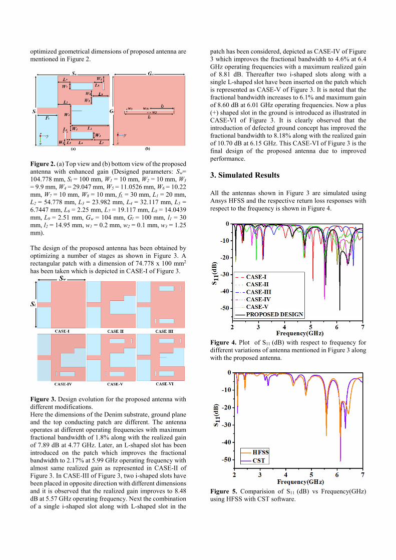
optimized geometrical dimensions of proposed antenna are mentioned in Figure 2.
Figure 2. (a) Top view and (b) bottom view of the proposed antenna with enhanced gain (Designed parameters: Sw= 104.778 mm, Sl = 100 mm, W1 = 10 mm, W2 = 10 mm, W3 = 9.9 mm, W4 = 29.047 mm, W5 = 11.0526 mm, W6 = 10.22 mm, W7 = 10 mm, W8 = 10 mm, fL = 30 mm, L1 = 20 mm, L2 = 54.778 mm, L3 = 23.982 mm, L4 = 32.117 mm, L5 = 6.7447 mm, L6 = 2.25 mm, L7 = 19.117 mm, L8 = 14.0439 mm, L9 = 2.51 mm, Gw = 104 mm, Gl = 100 mm, l1 = 30 mm, l2 = 14.95 mm, w1 = 0.2 mm, w2 = 0.1 mm, w3 = 1.25 mm). The design of the proposed antenna has been obtained by optimizing a number of stages as shown in Figure 3. A rectangular patch with a dimension of 74.778 x 100 mm2
has been taken which is depicted in CASE-I of Figure 3.
Figure 3. Design evolution for the proposed antenna with different modifications. Here the dimensions of the Denim substrate, ground plane and the top conducting patch are different. The antenna operates at different operating frequencies with maximum fractional bandwidth of 1.8% along with the realized gain of 7.89 dB at 4.77 GHz. Later, an L-shaped slot has been introduced on the patch which improves the fractional bandwidth to 2.17% at 5.99 GHz operating frequency with almost same realized gain as represented in CASE-II of Figure 3. In CASE-III of Figure 3, two i-shaped slots have been placed in opposite direction with different dimensions and it is observed that the realized gain improves to 8.48 dB at 5.57 GHz operating frequency. Next the combination of a single i-shaped slot along with L-shaped slot in the
patch has been considered, depicted as CASE-IV of Figure 3 which improves the fractional bandwidth to 4.6% at 6.4 GHz operating frequencies with a maximum realized gain of 8.81 dB. Thereafter two i-shaped slots along with a single L-shaped slot have been inserted on the patch which is represented as CASE-V of Figure 3. It is noted that the fractional bandwidth increases to 6.1% and maximum gain of 8.60 dB at 6.01 GHz operating frequencies. Now a plus (+) shaped slot in the ground is introduced as illustrated in CASE-VI of Figure 3. It is clearly observed that the introduction of defected ground concept has improved the fractional bandwidth to 8.18% along with the realized gain of 10.70 dB at 6.15 GHz. This CASE-VI of Figure 3 is the final design of the proposed antenna due to improved performance.
3. Simulated Results All the antennas shown in Figure 3 are simulated using Ansys HFSS and the respective return loss responses with respect to the frequency is shown in Figure 4.
Figure 4. Plot of S11 (dB) with respect to frequency for different variations of antenna mentioned in Figure 3 along with the proposed antenna.
Figure 5. Comparision of S11 (dB) vs Frequency(GHz) using HFSS with CST software.

The proposed antenna mentioned in Figure 1 operates at four different frequencies viz., 2.12 GHz, 4.78 GHz, 5.57 GHz and 6.11 GHz with fractional bandwidths of 0.94%, 1.04%, 2.5% and 8.18% respectively as shown in Figure 4. This antenna offers very good impedance matching at 6.11 GHz with a return loss of 51 dB. The introduction of different slots on the patch along with the slot in the ground plane improve the bandwidth along with the gain which partially covering S-band and C-band. Again from Figure 5, it is clearly observed that the simulated return loss obtained in HFSS is verified using CST Microwave Studio, which shows identical responses, thus validating the result. The electric field distributions at the top and bottom surface of the metallic patch have been shown in Figure 6(a) and Figure 6(b) respectively. It is observed that they are maximum around the slots and feed of the patch antenna at different operating frequencies of 2.12 GHz, 5.57 GHz and 6.15 GHz. The maximum field distribution has been observed at 6.15 GHz due to combined inductive and capacitive effects of the different slots in the patch as well as ground plane.
Figure 6. Simulated result of eletric field distribution of proposed antenna at different operating frequencies.
Figure 7. Simulated result of surface current of proposed antenna at different operating frequencies. The three dimensional polar plots at different frequencies viz., 2.12 GHz, 5.57 GHz, 5.64 GHz, 6.15 GHz, 6.43 GHz and 6.55 GHz are shown in Figure 8. It is observed that the proposed antenna exhibits the realized gain of 5.25 dB, 8.62 dB, 9.09 dB, 10.70 dB, 7.35 dB and 6.74 dB at the respective operating frequencies. The realized gain is high
over a band from 6.05 GHz to 6.55 GHz and the maximum gain of 10.70 dB has been achieved at 6.15 GHz.
Figure 8. Simulated result of 3D realized gain polar plot of proposed antenna at different operating frequencies. The E-plane (φ = 00) and H-plane (φ = 900) radiation characteristics of the proposed antenna at the operating frequencies of 2.12 GHz, 5.57 GHz and 6.15 GHz has been studied and shown in Figure 9(a) and Figure 9(b) respectively. In E-plane, endfire radiation characteristics are observed while unidirectional pattern is observed along H-plane. It is evident from Figure 9 that the cross-polarized level is 15 dB below than the co-polarized level at all the operating frequencies.
Figure 9. Co-polarized and Cross-polarized (a) E-plane and (b) H-plane at different operating frequencies within the proposed structure.
Table 1. Comparison of proposed antenna with existing antennas
Antenna Design
Fractional Bandwidth (%)
Gain (dB)
Zhu et al.[11] 2.0 3.14
Agneessens et al. [12] 4.8 4.2
Zhu et al. [13] 4 6.4
Agarwal et al.[14] 1.88 4.12
Proposed Antenna 8.18 10.70
The proposed structure has been compared with the existing reported antenna structures as shown in Table 1. It is observed that the proposed design exhibits optimum fractional bandwidth and significant gain in comparison to the reported ones.

4. Conclusion In this paper, the performance of textile based slotted rectangular patch antenna along with defected ground structure is analyzed and studied. The proposed antenna operates over four different frequencies viz., 2.12 GHz, 4.78 GHz, 5.57 GHz and 6.11 GHz with fractional bandwidths of 0.94%, 1.04%, 2.5% and 29.8%. The maximum return loss of 51 dB has been achieved over 6.05-6.55 GHz at 6.11 GHz. The simulated responses of the antenna using Ansys HFSS and CST Microwave Studio give rise to similar results. The maximum realized gain of 10.70 dB is obtained at 6.15 GHz. The antenna exhibits endfire radiation pattern in its far-field characteristics. It is applicable in maritime radar, radio LAN, radiolocation, passive sensor and weather radar applications, satellite communication and also in many communication fields. 5. References 1. S. Velan et al., "Dual-Band EBG Integrated Monopole Antenna Deploying Fractal Geometry for Wearable Applications," in IEEE Antennas and Wireless Propagation Letters, 14, September 2014, pp. 249-252, doi: 10.1109/LAWP.2014.2360710. 2. S. M. Saeed, C. A. Balanis, C. R. Birtcher, A. C. Durgun and H. N. Shaman, "Wearable Flexible Reconfigurable Antenna Integrated with Artificial Magnetic Conductor," in IEEE Antennas and Wireless Propagation Letters, 16, June 2017, pp.2396-2399, doi: 10.1109/LAWP.2017 .2720558. 3. G. Monti, L. Corchia, E. De Benedetto, and L. Tarricone, “Wearable logo-antenna for GPS–GSM-based tracking systems,” IET Microwaves Antennas and Propag. 10, 12, September 2016, pp. 1332–1338, doi: 10.1049/iet-map.2015.0774. 4. W. G. Whittow, A. Chauraya, J. C. Vardaxoglou et al., “Inkjet-printed Microstrip patch antennas realized on textile for wearable applications,” IEEE Antennas and Wireless Propagation Letters, 13, January 2014, pp. 71–74, doi: 10.1109/LAWP.2013.2295942. 5. H. R. Khaleel, H. M. Al-Rizzo, and A. I. Abbosh, “Design, fabrication and testing of flexible antennas,” Advancement in Microstrip Antennas with Recent Applications, InTech, March 2013, pp. 363-382 doi: 10.5772/50841. 6. A. Kiourti, C. Lee, and J. L. Volakis, “Fabrication of textile antennas and circuits with 0.1 mm precision,” IEEE Antennas and Wireless Propagation Letters, 15, pp. 151–153, May 2015, doi:10.1109/LAWP.2015.2435257. 7. I. Locher, M. Klemm, T. Kirstein, and G. Trster, “Design and characterization of purely textile patch antennas,”
IEEE Transactions on Advanced Packaging, 29, 4, Nov. 2006, pp. 777–788, doi: 10.1109/TADVP.2006.884780. 8. M. A. R. Osman, M. K. Abd Rahim, N. A. Samsuri, H. A. M. Salim, and M. F. Ali, “Embroidered fully textile wearable antenna for medical monitoring applications,” Progress in Electromagnetics Research, 117, May 2011, pp. 321–337, doi:10.2528/PIER11041208. 9. Z. Jiang, D. E. Brocker, P. E. Sieber, and D. H. Werner, “A compact, low-profile metasurface-enabled antenna for wearable medical body area network devices,” IEEE Trans. Antennas Propag., 62, 8, Aug. 2014, pp. 4021–4030, doi:10.1109/TAP.2014.2327650. 10. P. J. Soh, G. A. E. Vandenbosch, S. L. Ooi, and N. H. M. Rais,“Design of a Broadband all-Textile Slotted PIFA,” IEEE Transactions on Antennas and Propagation, 60, 1, Jan. 2012, pp. 379–384, doi: 10.1109/TAP.2011.2167950. 11. X.Q. Zhu, Y. X. Guo and W.Wu, “A compact dual-band antenna for wireless body-area network applications,” IEEE Antennas Wireless Propag. Lett. 15, May 2015, pp. 98–101, doi: 10.1109/LAWP.2015.2431822. 12. S. Agneessens, S. Lemey, T. Vervust, and H. Rogier, “Wearable, small and robust: The circular quarter-mode textile antenna,” IEEE Antennas Wireless Propag. Lett., 14, January 2015, pp. 1482–1485, doi: 10.1109/ LAWP.2015.2389630. 13. S. Zhu and R. Langley, “Dual-band wearable textile antenna on an EBG substrate,” IEEE Trans. Antennas Propagation., 57, 4, Apr. 2009, pp. 926–935, doi: 10.1109/TAP.2009.2014527. 14. K. Agarwal, Y. X. Guo, and B. Salam, “Wearable AMC backed near endfire antenna for on-body communications on latex substrate,” IEEE Transaction on Components, Packaging and Manufacturing Technology, 6, 3, Mar. 2016, pp. 346–358, doi: 10.1109/TCPMT.2016.2521487.