a modified simple interface fracture test for ceramic
TRANSCRIPT

TECHNICAL REPORT
A modified simple interface fracture test for ceramic environmentalbarrier coating on ceramic matrix composite
Hideki KAKISAWA1,³ and Toshiyuki NISHIMURA1
1National Institute for Materials Science, 1–2–1 Sengen, Tsukuba, Ibaraki 305–0047, Japan
A new interface fracture test was developed for ceramic environmental barrier coatings (EBCs) on ceramicmatrix composites (CMCs). The proposed test modifies an existing test in order to simplify specimen prepara-tion. An asymmetric double cantilever beam (ADCB) test specimen with a stiffener adhering to the coating wasused, and a wedge was inserted into the notch to open it. A formula to calculate interface toughness using thenotch opening load and displacement was derived; it was expanded so that the toughness could be obtained fromthe wedge insertion load and displacement. The interface toughness of a model EBC/substrate system consistingof a mullite layer and Si bond coat on a monolithic SiC plate was measured to examine the validity of the test.The obtained interface toughness was in good agreement with that obtained by the original test in the previousstudy. The interface to be fractured was controllable by adjusting the position of the notch.©2021 The Ceramic Society of Japan. All rights reserved.
Key-words : Interface toughness, Interface fracture test, Coating adhesion, Environmental barrier coating(EBC), Ceramic matrix composite (CMC)
[Received August 7, 2020; Accepted November 9, 2020]
1. Introduction
Environmental barrier coatings (EBCs) are essential forapplying SiC fiber-reinforced SiC matrix composites (SiC/SiCs) to hot sections of jet engines since SiC/SiCs arerapidly oxidized and volatilized in water-vapor-rich atmos-pheres of combustion gas.1)5) Usually EBCs are multi-layer coating systems designed to meet the demands ofprotective coatings: a top coat providing water shieldingcomposed of Ba1¹xSrxAl2Si2O8 (BSAS) or rare earth sili-cates (RE2Si2O7 and RE2SiO5) (RE: rare earth elementslike Y, Sc, and Yb); an intermediate layer of mullite ormullite/BSAS serving as an oxygen barrier that alsorelaxes thermal expansion mismatch; and a Si bond coatlayer for good adhesion to the substrate. These constitutivematerials have different Young’s moduli and coefficients ofthermal expansion (CTE); thermal stresses are induced onthe order of several hundreds of MPa after processing andduring heat cycles in use.6),7) Thus, thermomechanicaldurability is required for EBCs as well as chemical stabil-ity in the environment, even in quite severe heat cycleconditions ranging from ambient temperature to servicetemperatures of 13001400 °C.
EBCs usually have larger CTE than SiC/SiC sub-strates because the main components of EBCs are oxides;
in-plane tensile stress is induced in the coating when it iscooled. Such a stress condition with a brittle coating andsubstrate can induce several kinds of coating damage,8) asshown in Fig. 1: edge delamination, internal fracture in thecoating or substrate parallel to the interface, and transversecracking through the coating thickness followed by inter-face deflection or penetration to the substrate. This situa-tion is completely different from that in thermal barriercoating (TBC) systems on super alloy substrate; in-planecompressive stress is generated in the coating layer on theductile substrate, in which the main delamination mode isbuckling.8)
The damage mechanism of a realistic EBC system wasreported to be the ingress of the gaseous environment tothe interface between the mullite and Si bond coat layerthrough a transverse through-thickness crack (mud cracksin the top coat and intermediate coat) and the edge of thespecimens.9)12) This results in the formation of thermallygrown oxide (TGO) of ¢-cristobalite (SiO2) at the inter-face, and the volume change of the TGO during coolingcauses microcracking and consequently interface degrada-tion. By this degradation of the interface, edge delamina-tion and deflection of transverse cracking at the interface,which are illustrated as (a) and (c) in Fig. 1, are enhancedin those studies. Thus, the evaluation of delaminationresistance as a result of such degradation is a key issue, aswell as the initial resistance as processed. A quantitativeevaluation with physically meaningful parameters, e.g.,interface toughness, is required for the design and proc-essing selection of EBCs. More importantly, the interface
³ Corresponding author: H. Kakisawa; E-mail: [email protected]
‡ Preface for this article: DOI http://doi.org/10.2109/jcersj2.129.P1-1
Journal of the Ceramic Society of Japan 129 [1] 40-45 2021
DOI http://doi.org/10.2109/jcersj2.20167 JCS-Japan
©2021 The Ceramic Society of Japan40This is an Open Access article distributed under the terms of the Creative Commons Attribution License (https://creativecommons.org/licenses/by-nd/4.0/),which permits unrestricted use, distribution, and reproduction in any medium, provided the original work is properly cited.

toughness may be time-dependent because the degradationis accompanied by the progress of gaseous diffusion andthe formation of chemical product. The change in interfacetoughness with service time is also important for the lifeprediction of EBCs and the safe usage of SiC/SiCs.
Interface toughness depends strongly on the phaseangle, ¼, which is the measure of the stress state near theinterface crack tip. In dealing with interface fractures likeedge delamination and crack deflection of a transversecrack at the interface in EBCs, the importance of interfacefracture tests reproducing relatively low phase angles in-creases compared with the case we deal with the fracturesin TBC/superalloy systems. While there have been well-designed tests for TBCs that reproduce stress states withrelatively high phase angles (4560°),13)17) tests for lowphase angles have been lacking.18)
We previously proposed an asymmetric double canti-lever beam (ADCB) interface fracture test applicable toceramic EBCs on SiC/SiC substrates.19) The test is con-ducted with a small, simple-shape block specimen havinga notch and a pre-crack. It can delaminate the interfacewithout loading the SiC/SiC substrate, which may have aweaker interlaminar strength than the interface. We canobtain interfacial toughness with a relatively low phaseangle (<35°), unlike other interface fracture tests designedfor TBCs on metal substrates. The test has a fairly wideapplication range for coatings with various Young’s mod-uli, strengths, and thicknesses, but several problems stillremain: difficulty in applying to an interface with veryhigh interface toughness (over several tens of J/m2), a
slightly tangled pre-crack introduction procedure, and aneed for precise notch machining. In this study, we pro-pose a simpler interface fracture test, a modification of theoriginal test.
2. Proposed test
Two modifications of the previously proposed test aredone in this study. The specimen preparation procedure inthe original test includes the introduction of indentationcracks at the interface to be fractured, creation of pre-crackfrom the indentation crack and pre-crack dying. The intro-duction of controlled pre-crack is effective for accurate andreproducible measurement of interface toughness but theprocedure is somewhat complicated. In the modified test, along notch is machined so that the effect of geometry canbe minimized and the pre-crack introduction is omitted.As the second modification, a stiffener is adhered on thesurface of the coating. We discussed the application rangeof the original test where interface could be successfullyfractured before the bending fracture of the coatingoccurred; the results indicated that the bending fractureof the coating should be inevitable when a long notch,typically 2mm, is introduced. Thus, to meet both demandsof making a notch long and avoiding bending fracture ofthe coating, a hard plate stiffener is adhered to the coating.A schematic illustration of the proposed test is shown in
Fig. 2. A coated sample is cut into a block-type specimenwith a height of L0 and a width of b, and then a stiffenerwith a thickness of hA is adhered to the coating. A notchwith a width of w is introduced at the interface, which is
Fig. 1. Possible coating damage in the systems of brittle coating and substrate. (a)(d) may appear in a casewhere the CTE of the coating is larger than that of the substrate: (a) edge delamination, (b) internal fractureparallel to interface, (c) transverse cracking followed by deflection, and (d) transverse cracking and penetration tothe substrate. In a case where the CTE of the coating is smaller, the coating is compressed and buckling is themain damage mechanism with in-plane compressive stress in the coating, as shown in (e).
Journal of the Ceramic Society of Japan 129 [1] 40-45 2021 JCS-Japan
41
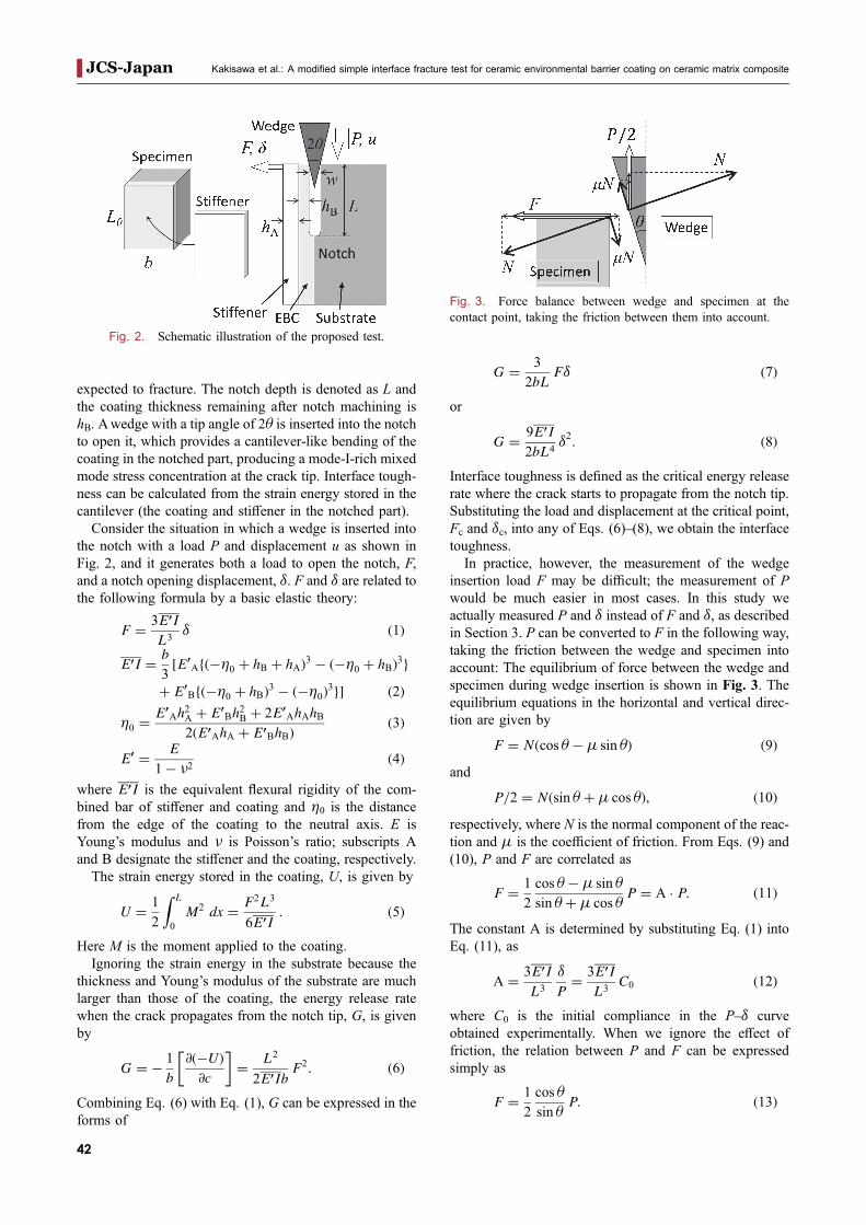
expected to fracture. The notch depth is denoted as L andthe coating thickness remaining after notch machining ishB. Awedge with a tip angle of 2ª is inserted into the notchto open it, which provides a cantilever-like bending of thecoating in the notched part, producing a mode-I-rich mixedmode stress concentration at the crack tip. Interface tough-ness can be calculated from the strain energy stored in thecantilever (the coating and stiffener in the notched part).
Consider the situation in which a wedge is inserted intothe notch with a load P and displacement u as shown inFig. 2, and it generates both a load to open the notch, F,and a notch opening displacement, ¤. F and ¤ are related tothe following formula by a basic elastic theory:
F ¼ 3E0IL3
¤ ð1Þ
E0I ¼ b
3½E0
Afð�©0 þ hB þ hAÞ3 � ð�©0 þ hBÞ3gþ E0
Bfð�©0 þ hBÞ3 � ð�©0Þ3g� ð2Þ
©0 ¼E0
Ah2A þ E0
Bh2B þ 2E0
AhAhB2ðE0
AhA þ E0BhBÞ
ð3Þ
E0 ¼ E
1� ¯2ð4Þ
where E0I is the equivalent flexural rigidity of the com-bined bar of stiffener and coating and ©0 is the distancefrom the edge of the coating to the neutral axis. E isYoung’s modulus and ¯ is Poisson’s ratio; subscripts Aand B designate the stiffener and the coating, respectively.
The strain energy stored in the coating, U, is given by
U ¼ 1
2
Z L
0
M2 dx ¼ F2L3
6E0I: ð5Þ
Here M is the moment applied to the coating.Ignoring the strain energy in the substrate because the
thickness and Young’s modulus of the substrate are muchlarger than those of the coating, the energy release ratewhen the crack propagates from the notch tip, G, is givenby
G ¼ � 1
b
@ð�UÞ@c
� �¼ L2
2E0IbF2: ð6Þ
Combining Eq. (6) with Eq. (1), G can be expressed in theforms of
G ¼ 3
2bLF¤ ð7Þ
or
G ¼ 9E0I2bL4
¤2: ð8Þ
Interface toughness is defined as the critical energy releaserate where the crack starts to propagate from the notch tip.Substituting the load and displacement at the critical point,Fc and ¤c, into any of Eqs. (6)(8), we obtain the interfacetoughness.In practice, however, the measurement of the wedge
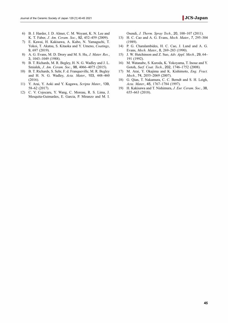
insertion load F may be difficult; the measurement of Pwould be much easier in most cases. In this study weactually measured P and ¤ instead of F and ¤, as describedin Section 3. P can be converted to F in the following way,taking the friction between the wedge and specimen intoaccount: The equilibrium of force between the wedge andspecimen during wedge insertion is shown in Fig. 3. Theequilibrium equations in the horizontal and vertical direc-tion are given by
F ¼ Nðcos ª �® sin ªÞ ð9Þand
P=2 ¼ Nðsin ª þ® cos ªÞ; ð10Þrespectively, where N is the normal component of the reac-tion and ® is the coefficient of friction. From Eqs. (9) and(10), P and F are correlated as
F ¼ 1
2
cos ª �® sin ª
sin ª þ® cos ªP ¼ A � P: ð11Þ
The constant A is determined by substituting Eq. (1) intoEq. (11), as
A ¼ 3E0IL3
¤
P¼ 3E0I
L3C0 ð12Þ
where C0 is the initial compliance in the P¤ curveobtained experimentally. When we ignore the effect offriction, the relation between P and F can be expressedsimply as
F ¼ 1
2
cos ª
sin ªP: ð13Þ
Fig. 3. Force balance between wedge and specimen at thecontact point, taking the friction between them into account.
Fig. 2. Schematic illustration of the proposed test.
Kakisawa et al.: A modified simple interface fracture test for ceramic environmental barrier coating on ceramic matrix compositeJCS-Japan
42

Further, when we have difficulties in measuring ¤, thedisplacement of the wedge, u, can be used as a substitutionby the following conversion:
¤ ¼ 2u tan ª: ð14Þ
3. Experimental procedure
3.1 MaterialA multilayer coating system consisting of a Si bond coat
layer and a mullite layer on a monolithic SiC substrate wasused as the test material. We used the same material as inthe previous study proposing the evaluation method so thatwe could compared the present and previous results. TheSi bond coat was deposited by atmospheric plasma spray(APS) with a designed thickness of 100¯m. Then themullite layer was coated by APS on the Si layer with thethickness set at 250¯m. Young’s moduli of the respectivelayers were measured by nano-indentation, and 126GPafor the Si bond coat layer and 132GPa for the mullite layerwere obtained. The previous paper contains more detailsabout the processing and characteristics of the material.19)
The coated material was cut into the specimen with aheight (L0) of 4mm and a width (b) of 3mm. The widthwas determined by reference to the bending fracture teststandardized in Japanese Industrial Standard 1607(JIS1607) so that a plane strain could be assured. Thesurface was finished as cut without polishing. A sintered¡-alumina plate with a thickness of ³250¯m, one plane ofwhich was mirror polished, was prepared and cut into a4 © 3mm rectangle; it was used as to stiffen the coating.The unpolished plane of the cut plate and the coatingsurface of the specimen were bonded with epoxy adhesive(Araldite 2011: Huntsman Corporation, The Woodlands,TX, USA). The detail of the bonding procedure is asfollows. The epoxy adhesive was spread on both the sur-face of the specimen and the stiffener, which then bondedtogether. The side and corner of the specimen and stiffenerwere exactly lined up using an alignment jig. Then thebonded specimen and stiffener were compressed with a flatpunch with a load of ³100N to remove porosity in theadhesive and extrude the excess adhesive from the sides.The resultant thickness of the adhesive layer was less than10¯m. The epoxy was hardened at room temperature fora day, and then the excess adhesive on the sides of thespecimen was removed with a craft knife.
A notch was introduced using a diamond wire saw (wirediameter: 200¯m) along the interface to a half depth of thespecimen, L = ³2mm. The cutting wire and the interfacewere aligned using a digital microscope so that the centerline of the notch could overlap either the interface betweenthe mullite and the Si layer or between the Si layer and thesubstrate.
3.2 Interface fracture testThe setup of the test equipment is illustrated in Fig. 4.
The wedge was made by cutting a commercial steel craftknife. The thickness of the wedge was 0.5mm, and its tipwas sharpened with a wedge angle (2ª) of 16°. The test
was conducted by inserting the wedge into the notch at aconstant speed of 12¯m/min using a universal testingmachine (EZ-LX: Shimadzu Corporation, Kyoto, Japan).A load cell with a capacity of 50N attached to the machinewas used to measure the wedge insertion load during thetest, P. The notch opening displacement during the test wasmeasured by a spectral interference displacement sensor[SI-F1000V (SI-F10): Keyence, Osaka, Japan]; the dis-tance from the sensor to the upper part of the stiffenersurface was measured as the displacement. The mirror-polished surface of the stiffener contributed to stable andreliable displacement measurement.
4. Results and discussion
Figure 5 shows an example of the relation between thewedge insertion load, P, and notch opening displacement,¤, during the test. The load increased linearly with dis-placement as the wedge was inserted. Then the load devi-ated from the linear increase at the point when the delami-nation started, but still continued to increase. After the loadreached the maximum, it decreased gradually and finallydropped to almost zero when the coating was completelydelaminated. The wedge progressed in the notch smoothlywithout stick-slip throughout the test.
Fig. 4. Setup of test equipment.
Fig. 5. Example of the relation between wedge insertion loadand notch opening displacement during the test. Point C indicatesthe end of the linear load-displacement relation.
Journal of the Ceramic Society of Japan 129 [1] 40-45 2021 JCS-Japan
43

Figure 6 shows the side surface of the specimen afterthe test. A crack path can be identified from the sidesurface observation of the specimen. These paths wereclassified into three types: the path along the interfacebetween the mullite and Si layers, the path along theinterface between the Si layer and the substrate, and thepath within the Si layer along the splat boundaries formedduring APS processing. These crack paths were dependenton the notch position. Crack initiation tended to occur at apoint shifted from the center of the notch to the coatingside, where the largest stress concentration ought to occurdue to the ADCB geometry of the specimen. This sug-gested that we can control the interface which should befractured to some extent by changing the position wherethe notch is introduced. However, note that the fracturedoes not necessarily occur at the point where the largeststress concentration is generated but at the weakest point,which satisfies the fracture criteria first.
Interface toughness was determined from the wedgeinsertion load and notch opening displacement. Assumingthat the crack began propagating at the point where thelinear load-displacement relation finished, C(Pc, ¤c) (seeFig. 6), interface toughness ¥i was calculated by substitut-ing Pc and ¤c into Eqs. (7), (11), and (12), as
�i ¼3A
2bLPc¤c: ð15Þ
Thus, the obtained toughness is the so-called “initial”interface toughness when the crack starts to propagate. Thetoughnesses of the three interface fracture paths weredetermined. At least three successful tests for each type offracture path were used in the calculations. Exactly, E0Ishould be calculated based on the interface fracture actu-ally occurs; e.g., when the fracture occurs at the interfacebetween the Si layer and the substrate, E0I is the equiva-lent flexural rigidity of stiffener, mullite layer and Si layer,as done in Ref. 19. However in this study the effect wasignored because Young’s modulus and the thickness of Silayers is much smaller those of the stiffener.
The measured interface toughness between the Si layerand the substrate was 4.3 J/m2 with a standard deviation(s.d.) of 0.29; this value was in good agreement with theone obtained in the previous study (4.1 J/m2) by the test.19)
Although a pre-crack was not intentionally introduced inthis study, the effect of that was likely to be small. Indouble beam cantilever-type specimens, a crack tends topropagate stably due to the geometric effect. Thus anunintentional very small defect or damage near the notchtip might cause the origin of the stable fracture in an earlystage of the loading (before we can detect the end of thelinear relation), and the formed crack might act as the pre-crack. The influences of the utilization of the stiffener ontest results such as the geometry effect and the phase anglechange near the notch tip should be precisely evaluatedfurther; the proposed test seems useful as a simple sub-stitute for the original test. The test is supposed to providea smaller phase angle than the original test because theexistence of a stiffener reduces the asymmetry of geometryand rigidity in the specimen, which would be of help forstrict evaluation of interface toughness as a function ofphase angle. For the interface fracture between the Si andmullite layers, interface toughness of 9.2 J/m2 with s.d. of2.2 was measured; for the fracture within the Si layer, 6.6J/m2 with s.d. of 0.31 was measured.
5. Conclusion
A new fracture test measuring the interface toughness ofEBCs on ceramic matrix composite substrate was pro-posed by modifying an existing test. A long notch wasintroduced instead of pre-crack and a stiffener was appliedto reinforce the cantilever part of the coating in the ADCBspecimen. The interface toughness obtained by the testagreed well with the one measured in the original test eventhough the introduction of pre-crack, pre-crack dying, andpre-crack depth measurement were omitted, suggesting thevalidity of the proposed test. This is advantageous for thesimplification of the specimen preparation. Although fur-ther analyses for phase angle evaluation and geometryeffect are needed for assuring the accuracy of the test, theusefulness of the test was shown.
Acknowledgments The authors would like to thankKaori Sakata for technical assistance. This work was sup-ported by the Council for Science, Technology and Innova-tion (CSTI), Cross-ministerial Strategic Innovation PromotionProgram (SIP), “Structural Materials for Innovation” [Fund-ing agency: Japan Science and Technology Agency (JST)].
References1) K. N. Lee, Surf. Coat. Tech., 133–134, 17 (2000).2) K. N. Lee, D. S. Fox and N. P. Bansal, J. Eur. Ceram.
Soc., 25, 17051715 (2005).3) B. T. Richards and H. N. G. Wadley, J. Eur. Ceram.
Soc., 34, 30693083 (2014).4) C. V. Cojocaru, D. Lévesque, C. Moreau and R. S.
Lima, Surf. Coat. Tech., 216, 215223 (2013).5) E. García, P. Miranzo and M. I. Osendi, J. Therm. Spray
Tech., 22, 680689 (2013).
Fig. 6. Crack path observed from the side surface after the test.Crack propagating from the notch tip is indicated by the arrow.The figure shows an example of where the crack propagatesalong the interface between the mullite and Si bond coat layers.
Kakisawa et al.: A modified simple interface fracture test for ceramic environmental barrier coating on ceramic matrix compositeJCS-Japan
44
6) B. J. Harder, J. D. Almer, C. M. Weyant, K. N. Lee andK. T. Faber, J. Am. Ceram. Soc., 92, 452459 (2009).
7) E. Kawai, H. Kakisawa, A. Kubo, N. Yamaguchi, T.Yokoi, T. Akatsu, S. Kitaoka and Y. Umeno, Coatings,9, 697 (2019).
8) A. G. Evans, M. D. Drory and M. S. Hu, J. Mater. Res.,3, 10431049 (1988).
9) B. T. Richards, M. R. Begley, H. N. G. Wadley and J. L.Smialek, J. Am. Ceram. Soc., 98, 40664075 (2015).
10) B. T. Richards, S. Sehr, F. d. Franqueville, M. R. Begleyand H. N. G. Wadley, Acta. Mater., 103, 448460(2016).
11) Y. Arai, Y. Aoki and Y. Kagawa, Scripta Mater., 139,5862 (2017).
12) C. V. Cojocaru, Y. Wang, C. Moreau, R. S. Lima, J.Mesquita-Guimarães, E. Garcia, P. Miranzo and M. I.
Osendi, J. Therm. Spray Tech., 20, 100107 (2011).13) H. C. Cao and A. G. Evans, Mech. Mater., 7, 295304
(1989).14) P. G. Charalambides, H. C. Cao, J. Lund and A. G.
Evans, Mech. Mater., 8, 269283 (1990).15) J. W. Hutchinson and Z. Suo, Adv. Appl. Mech., 29, 64
191 (1992).16) M. Watanabe, S. Kuroda, K. Yokoyama, T. Inoue and Y.
Gotoh, Surf. Coat. Tech., 202, 17461752 (2008).17) M. Arai, Y. Okajima and K. Kishimoto, Eng. Fract.
Mech., 74, 20552069 (2007).18) G. Qian, T. Nakamura, C. C. Berndt and S. H. Leigh,
Acta. Mater., 45, 17671784 (1997).19) H. Kakisawa and T. Nishimura, J. Eur. Ceram. Soc., 38,
655663 (2018).
Journal of the Ceramic Society of Japan 129 [1] 40-45 2021 JCS-Japan
45