a model for controlled dosing of femto-litre volume ... fileifac papersonline 50-1 (2017)...
TRANSCRIPT

Delft University of Technology
A model for controlled dosing of femto-litre volume liquids using hollow microcantilever
Cao, Xi; Gruiter, Rick de; van Oorschot, Ralph; Baldi, Simone; Hossein Nia Kani, Hassan; Ghatkesar, Murali
DOI10.1016/j.ifacol.2017.08.2141Publication date2017Document VersionFinal published versionPublished inIFAC-PapersOnLine
Citation (APA)Cao, X., Gruiter, R. D., van Oorschot, R., Baldi, S., Hossein Nia Kani, H., & Ghatkesar, M. K. (2017). Amodel for controlled dosing of femto-litre volume liquids using hollow microcantilever. IFAC-PapersOnLine,50(1), 15542-15547. https://doi.org/10.1016/j.ifacol.2017.08.2141
Important noteTo cite this publication, please use the final published version (if applicable).Please check the document version above.
CopyrightOther than for strictly personal use, it is not permitted to download, forward or distribute the text or part of it, without the consentof the author(s) and/or copyright holder(s), unless the work is under an open content license such as Creative Commons.
Takedown policyPlease contact us and provide details if you believe this document breaches copyrights.We will remove access to the work immediately and investigate your claim.
This work is downloaded from Delft University of Technology.For technical reasons the number of authors shown on this cover page is limited to a maximum of 10.

IFAC PapersOnLine 50-1 (2017) 15542–15547
ScienceDirect
Available online at www.sciencedirect.com
2405-8963 © 2017, IFAC (International Federation of Automatic Control) Hosting by Elsevier Ltd. All rights reserved.Peer review under responsibility of International Federation of Automatic Control.10.1016/j.ifacol.2017.08.2141
© 2017, IFAC (International Federation of Automatic Control) Hosting by Elsevier Ltd. All rights reserved.
10.1016/j.ifacol.2017.08.2141 2405-8963
A model for controlled dosing of femto-litrevolume liquids using hollow microcantilever
Xi Cao1,∗, Rick de Gruiter2, Ralph van Oorschot3,Simone Baldi1, Hassan HosseinNia2,
Murali Krishna Ghatkesar2,∗∗
1 Delft Center for Systems and Control, Delft University of Technology, TheNetherlands,
2 Precision and Microsystems Engineering, Delft University of Technology, TheNetherlands,
3 MA3 Solutions B.V., Eindhoven, The Netherlands.∗[email protected]; ∗∗[email protected]
Abstract: A hollow microcantilever is used instead of a conventional microcantilever to dispenseand aspirate liquids in the femto-litre (10−15 L) volume range in an atomic force microscope(AFM) setup. The inherent force sensing capability of the cantilever is used to monitor the fluidmanipulation in-situ. At this small scale, parameters like: surface energy, evaporation, viscosityand temperature become important for controlled manipulation. In a conventional AFM, theseparameters are usually not taken into consideration as feedback parameters. In the presentwork, we report initial experimental results on the dosing process and an analytical dynamicmodel of the process. The model is based on the liquid bridge between the cantilever tip andthe substrate, which can describe the dosing process with variance accounted for (VAF) largerthan 90%. We aim to use this model and implement a control system for precise dispensing andaspiration.
Keywords: dynamic modelling, hollow-cantilever, nanotechnology, femto-liter, Atomic ForceMicroscope
1. INTRODUCTION
Nanotechnology has been first introduced by RichardFeynman in 1959. In 1990s, the interest in nanotechnologygreatly increased (Elnashaie et al. (2015)), and nowdays,a lot of branches in nanotechnology have arisen: handlingliquids at nanoscale is one of them, with applications insurface nanopatterning or molecules deposition on sur-faces. Atomic force microscope (AFM) has become a cru-cial enabler of dosing liquids in the order of femtoliter.Three different types of AFM-based tools are used fordosing liquids at the femtoliter scale (Ghatkesar et al.(2014)): the first one is the chip without reservoir, calledas DPN (Dip Pen Nanolithography). The second one isthe chip with a reservoir just above the tip of AFM(hollow tip), called as NADIS (Nanoscale Dispensing). Thethird one is the chip with a reservoir: the liquid can flowfrom on-chip reservoir through the hollow cantilever anddispensed from the aperture at the tip, such as AFM-FP (atomic force microscope femto pipette) and NFProbe(Nanofountain Probe). The hollow cantilever AFM has theadvantage that it could both aspirate and dispense liquids,if connected with a pressure control system. So it opensthe possibility to control the dosing process dynamics viaa properly designed applied pressure. However, a dynamicmodel is the necessary first step for the initiation of suchcontrol system. The goal of this work is modeling thedosing dynamics happening in an AFM-FP.
The first contribution of this work arises from the factthat while the state of the art provides us only withexperimental data and empirical analysis about factorsinfluencing the dispensing process of NADIS and DPN(Fabie et al. (2009); OConnell et al. (2014)), in this paper,a dynamic model of the dosing process is formulated for thefirst time. Two principles (Laplace pressure and electricalcircuit analogy method) are appropriately combined todevelop the dynamic model.
The second contribution of this work is the validation ofthe dynamic model, via a set of appropriately designeddosing experiments: it is demonstrated that the proposedmodel can describe the dosing process with variance ac-counted for (VAF) larger than 90%. VAF is used to assessthe quality of a model, which is defined as:
V AF = (1−1N
∑Nk=1 ‖y(k)− ym((k))‖221N
∑Nk=1 ‖y(k)‖22
)× 100%
where y(k) is the experimental data and ym(k) is the datafrom model. VAF values close to 100% indicates that themodel is a good representation of the physical process.
The rest of the paper is organized as follows. Section 2introduces the dosing process. Section 3 explains the mod-eling steps. In Section 4 experimental methods to measurevolume and contact angle are explained. Experimentalresults with model validation are illustrated in Section 5.Section 6 concludes the paper and discusses future work.
Proceedings of the 20th World CongressThe International Federation of Automatic ControlToulouse, France, July 9-14, 2017
Copyright © 2017 IFAC 16112
2. THE DOSING PROCESS
”Dosing” means putting a desired volume of liquids ina specific position of the substrate by dispensing andaspirating. The dosing device comprises AFM-FP, climatecontrol system and pressure control system (van Oorschotet al. (2015)). The dosing process steps are shown Figure 1.The corresponding cantilever deflection signal monitoredwith distance above the substrate surface is shown inFigure 2.
In step 1, the hollow cantilever approaches the substratewith a constant step size. It is the distance which thehollow cantilever AFM tip moves vertically in a specificperiod.
In step 2, the tip touches the substrate, and the externalpressure control system provides pressure for a certain pe-riod. The position where the tip first touches the substrateis the snap in position. The blue line in Figure 2 representsthe signal from step 1 and step 2. The contact periodis called contact time. And the liquid connecting tip andsubstrate is called liquid bridge.
In step 3, the tip starts to retract from the substrate at thesame step size. After the liquid bridge breaks up, the liquiddroplet remains on the substrate, which represent the step4 of the process. The red line in Figure 2 represents thesignal from step 3 and step 4.
The contact angle β (rad) is measured through the liquid,where a liquid-vapor interface meets a solid surface. Instep 2, θd (rad) is called the dynamic contact angle. Whenpositive pressure is provided, the three phase boundary ofliquid bridge increases, then the angle is called advancingcontact angle. When negative pressure is provided, thethree phase boundary of liquid bridge decreases, then theangle is called receding contact angle.
The distance between the tip of hollow cantilever andsubstrate at the instance the liquid bridge breaks h (m)in step 3 is called break-up height. The break-up height isobtained from Figure (2). There is a difference between theapproach (blue) and retract (red) curves because when thetip retracts there is a liquid bridge connecting the AFM-tip and the substrate. Liquid bridge breaking occurs whenthe red line suddenly coincides with the blue line. Thebreak-up height is calculated by subtracting the snap inposition from the break-up position.
3. MODELING THE DOSING PROCESS
3.1 Flow rate
For uniform-viscous and incompressible Newtonian fluidswith no body forces, the flow rate in a channel can bederived as in (Oh et al. (2012)) according to the electricalcircuit analogy method:
Q =∆P
RH(1)
where Q (m3/s) is the volumetric flow rate, ∆P (Pa) isthe pressure difference, RH (Pa · s/m3) is the hydraulicresistance.
Fig. 1. Dosing process in four steps. These steps arerepeated till the desired volume is achieved.
Fig. 2. The deflection of the cantilever with vertical posi-tion is shown. The blue line represents the cantileverapproaching the substrate and the red line representsthe cantilever retracting from the substrate.
The pressure of the liquid bridge will be calculated usingthe Laplace pressure formula. ”The Laplace pressure is thepressure difference between the inside and the outside ofa curved surface that forms the boundary between a gasregion and a liquid region.” (Butt et al. (2006)), which canbe written as (Quere et al. (2004)):
∆P = Pinside − Poutside = γH (2)
where Pinside (Pa) is the pressure inside the curved surface,Poutside is the pressure outside the curved surface, H(1/m) is the curvature of the surface, which is sum ofthe two principle curvatures and γ (N/m) is the surfacetension of the liquid.
3.2 Dynamic model
The scheme of the dosing process is shown in Figure 3. Wedefine the following quantities:
∆Pp = Pp − Patm, ∆Pm = Pm − Patm (3)
where Pp (Pa) is the pressure provided by pressure controlsystem, Pm (Pa) is the pressure in the liquid bridge andPatm (Pa) is the pressure of the atmosphere.Then the flow rate Q can be expressed by the followingdifferential equation with the hydraulic resistance RH ofthe system:
dV
dt= Q =
∆Pp −∆Pm
RH(4)
Proceedings of the 20th IFAC World CongressToulouse, France, July 9-14, 2017
16113

Xi Cao et al. / IFAC PapersOnLine 50-1 (2017) 15542–15547 15543
A model for controlled dosing of femto-litrevolume liquids using hollow microcantilever
Xi Cao1,∗, Rick de Gruiter2, Ralph van Oorschot3,Simone Baldi1, Hassan HosseinNia2,
Murali Krishna Ghatkesar2,∗∗
1 Delft Center for Systems and Control, Delft University of Technology, TheNetherlands,
2 Precision and Microsystems Engineering, Delft University of Technology, TheNetherlands,
3 MA3 Solutions B.V., Eindhoven, The Netherlands.∗[email protected]; ∗∗[email protected]
Abstract: A hollow microcantilever is used instead of a conventional microcantilever to dispenseand aspirate liquids in the femto-litre (10−15 L) volume range in an atomic force microscope(AFM) setup. The inherent force sensing capability of the cantilever is used to monitor the fluidmanipulation in-situ. At this small scale, parameters like: surface energy, evaporation, viscosityand temperature become important for controlled manipulation. In a conventional AFM, theseparameters are usually not taken into consideration as feedback parameters. In the presentwork, we report initial experimental results on the dosing process and an analytical dynamicmodel of the process. The model is based on the liquid bridge between the cantilever tip andthe substrate, which can describe the dosing process with variance accounted for (VAF) largerthan 90%. We aim to use this model and implement a control system for precise dispensing andaspiration.
Keywords: dynamic modelling, hollow-cantilever, nanotechnology, femto-liter, Atomic ForceMicroscope
1. INTRODUCTION
Nanotechnology has been first introduced by RichardFeynman in 1959. In 1990s, the interest in nanotechnologygreatly increased (Elnashaie et al. (2015)), and nowdays,a lot of branches in nanotechnology have arisen: handlingliquids at nanoscale is one of them, with applications insurface nanopatterning or molecules deposition on sur-faces. Atomic force microscope (AFM) has become a cru-cial enabler of dosing liquids in the order of femtoliter.Three different types of AFM-based tools are used fordosing liquids at the femtoliter scale (Ghatkesar et al.(2014)): the first one is the chip without reservoir, calledas DPN (Dip Pen Nanolithography). The second one isthe chip with a reservoir just above the tip of AFM(hollow tip), called as NADIS (Nanoscale Dispensing). Thethird one is the chip with a reservoir: the liquid can flowfrom on-chip reservoir through the hollow cantilever anddispensed from the aperture at the tip, such as AFM-FP (atomic force microscope femto pipette) and NFProbe(Nanofountain Probe). The hollow cantilever AFM has theadvantage that it could both aspirate and dispense liquids,if connected with a pressure control system. So it opensthe possibility to control the dosing process dynamics viaa properly designed applied pressure. However, a dynamicmodel is the necessary first step for the initiation of suchcontrol system. The goal of this work is modeling thedosing dynamics happening in an AFM-FP.
The first contribution of this work arises from the factthat while the state of the art provides us only withexperimental data and empirical analysis about factorsinfluencing the dispensing process of NADIS and DPN(Fabie et al. (2009); OConnell et al. (2014)), in this paper,a dynamic model of the dosing process is formulated for thefirst time. Two principles (Laplace pressure and electricalcircuit analogy method) are appropriately combined todevelop the dynamic model.
The second contribution of this work is the validation ofthe dynamic model, via a set of appropriately designeddosing experiments: it is demonstrated that the proposedmodel can describe the dosing process with variance ac-counted for (VAF) larger than 90%. VAF is used to assessthe quality of a model, which is defined as:
V AF = (1−1N
∑Nk=1 ‖y(k)− ym((k))‖221N
∑Nk=1 ‖y(k)‖22
)× 100%
where y(k) is the experimental data and ym(k) is the datafrom model. VAF values close to 100% indicates that themodel is a good representation of the physical process.
The rest of the paper is organized as follows. Section 2introduces the dosing process. Section 3 explains the mod-eling steps. In Section 4 experimental methods to measurevolume and contact angle are explained. Experimentalresults with model validation are illustrated in Section 5.Section 6 concludes the paper and discusses future work.
Proceedings of the 20th World CongressThe International Federation of Automatic ControlToulouse, France, July 9-14, 2017
Copyright © 2017 IFAC 16112
2. THE DOSING PROCESS
”Dosing” means putting a desired volume of liquids ina specific position of the substrate by dispensing andaspirating. The dosing device comprises AFM-FP, climatecontrol system and pressure control system (van Oorschotet al. (2015)). The dosing process steps are shown Figure 1.The corresponding cantilever deflection signal monitoredwith distance above the substrate surface is shown inFigure 2.
In step 1, the hollow cantilever approaches the substratewith a constant step size. It is the distance which thehollow cantilever AFM tip moves vertically in a specificperiod.
In step 2, the tip touches the substrate, and the externalpressure control system provides pressure for a certain pe-riod. The position where the tip first touches the substrateis the snap in position. The blue line in Figure 2 representsthe signal from step 1 and step 2. The contact periodis called contact time. And the liquid connecting tip andsubstrate is called liquid bridge.
In step 3, the tip starts to retract from the substrate at thesame step size. After the liquid bridge breaks up, the liquiddroplet remains on the substrate, which represent the step4 of the process. The red line in Figure 2 represents thesignal from step 3 and step 4.
The contact angle β (rad) is measured through the liquid,where a liquid-vapor interface meets a solid surface. Instep 2, θd (rad) is called the dynamic contact angle. Whenpositive pressure is provided, the three phase boundary ofliquid bridge increases, then the angle is called advancingcontact angle. When negative pressure is provided, thethree phase boundary of liquid bridge decreases, then theangle is called receding contact angle.
The distance between the tip of hollow cantilever andsubstrate at the instance the liquid bridge breaks h (m)in step 3 is called break-up height. The break-up height isobtained from Figure (2). There is a difference between theapproach (blue) and retract (red) curves because when thetip retracts there is a liquid bridge connecting the AFM-tip and the substrate. Liquid bridge breaking occurs whenthe red line suddenly coincides with the blue line. Thebreak-up height is calculated by subtracting the snap inposition from the break-up position.
3. MODELING THE DOSING PROCESS
3.1 Flow rate
For uniform-viscous and incompressible Newtonian fluidswith no body forces, the flow rate in a channel can bederived as in (Oh et al. (2012)) according to the electricalcircuit analogy method:
Q =∆P
RH(1)
where Q (m3/s) is the volumetric flow rate, ∆P (Pa) isthe pressure difference, RH (Pa · s/m3) is the hydraulicresistance.
Fig. 1. Dosing process in four steps. These steps arerepeated till the desired volume is achieved.
Fig. 2. The deflection of the cantilever with vertical posi-tion is shown. The blue line represents the cantileverapproaching the substrate and the red line representsthe cantilever retracting from the substrate.
The pressure of the liquid bridge will be calculated usingthe Laplace pressure formula. ”The Laplace pressure is thepressure difference between the inside and the outside ofa curved surface that forms the boundary between a gasregion and a liquid region.” (Butt et al. (2006)), which canbe written as (Quere et al. (2004)):
∆P = Pinside − Poutside = γH (2)
where Pinside (Pa) is the pressure inside the curved surface,Poutside is the pressure outside the curved surface, H(1/m) is the curvature of the surface, which is sum ofthe two principle curvatures and γ (N/m) is the surfacetension of the liquid.
3.2 Dynamic model
The scheme of the dosing process is shown in Figure 3. Wedefine the following quantities:
∆Pp = Pp − Patm, ∆Pm = Pm − Patm (3)
where Pp (Pa) is the pressure provided by pressure controlsystem, Pm (Pa) is the pressure in the liquid bridge andPatm (Pa) is the pressure of the atmosphere.Then the flow rate Q can be expressed by the followingdifferential equation with the hydraulic resistance RH ofthe system:
dV
dt= Q =
∆Pp −∆Pm
RH(4)
Proceedings of the 20th IFAC World CongressToulouse, France, July 9-14, 2017
16113

15544 Xi Cao et al. / IFAC PapersOnLine 50-1 (2017) 15542–15547
where, V (m3) is the volume of the liquid bridge. Because∆Pp is the system input, what needs to be determinedis ∆Pm. In particular, since the output of the system isthe volume of the liquid bridge, it is necessary to find arelation between ∆Pm and the volume. The model wouldbecome:
dV
dt=
∆Pp −∆Pm(V )
RH(5)
The method to obtain the relation between pressure andvolume is introduced in the following.
Fig. 3. The schematic of AFM-FP. The liquid is modelledas a uniform-viscous and incompressible Newtonianfluid (courtesy of Dr. Hector Hugo Perez Garza).
3.3 Young-Laplace equation
The profile of an axisymmetric liquid bridge between twosolid surfaces can be described by solving Young-Laplaceequation (Asay et al. (2010); Orr et al. (1975); Melrose(1966)). The tip of hollow cantilever can be approximatedas cone. When the curvature of liquid bridge is negative,and the distance between the tip and substrate is D (seeFigure 4), by solving the Young-Laplace equation, we canobtain:
2HmeanR1 =1
d{− cos(θ1 + ψ)− cos(θ2)−
1
k[E(φ2, k)−
E(φ1, k)] +1− k2
k[F (φ2, k)− F (φ1, k)]}
(6)
where
k = (1
1 + c)1/2
c = 4H2meanR
2 sin2(ψ)− 4HmeamR sin(ψ)sin(θ1 + ψ)
φ1 = −(θ1 + ψ) + 1/2π
φ2 = θ2 − 1/2π
d =y1 +D
R1=
1
tan(π2 − ψ)sinψ +
D
R1
Hmean is the mean of the two principle curvatures, which is2Hmean = H; R1 is the radius of the circle which is tangentto the edge of the cone and pass through the point wherethe liquid bridge is connected to the cone. We define c1 as:
2HmeanR1 = HR1 = c1 (7)
y1 is the height of that point; θ1 is the contact anglebetween the liquid and tip; θ2 is the contact angle betweenliquid and substrate; F is the elliptic integral of first kindand E is the elliptic integral of second kind. Dynamiccontact angle has a complex behavior for different liquids.For most liquids the advancing angle is the same when the
radius of droplet increases (Kwok and Neumann (1999)).The receding angle is more complex than the advancingcontact angle. The receding contact angle can change withvolume (Lam et al. (2002)). For small volumes, it is easyfor the three phase boundary of liquid bridge to increasewith increase in volume (Korhonen et al. (2013)). Whenconsidering dispensing process via hollow cantilever (forsmall volume), the angles θ1, θ2 (advancing contact angles)in (6) can be treated as constant values, and the distancebetween the tip and substrate D is zero. As a result (6)becomes an equation with the only variable HmeanR1. Soc1 is constant in this condition.
As for the aspirating process, because θ1 and θ2 may notbe constant, c1 may change with volume and time.
Fig. 4. Liquid bridge between a cone and plane.
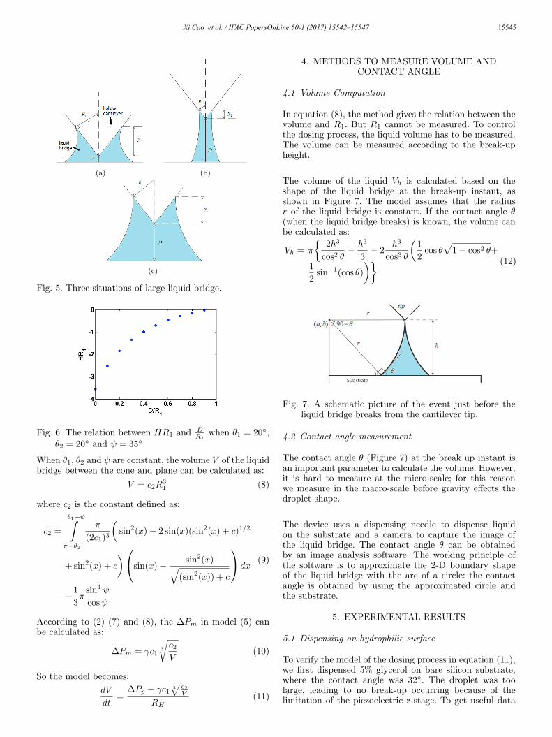
If the distance D between the tip and substrate is notzero, c1 will change when the volume changes. As for largevolume of liquid bridge, there are three situations, whichis shown in Figure 5.
In the situation (a), the distance D is small, but R1 andy1 are large. In the situation (b), the distance D is large,while R1 and y1 are small. In the situation (c), D, R1 and
y1 are large. Because d = y1+DR1
, in the situation (a), the
part DR1
can be neglected, d can be approximated as thesituation when the distance D is zero.
In the situation (b), D is much larger than R1 and y1.The relation between HR1 and the ratio of D
R1is shown in
the Figure 6 where θ1 = 20◦, θ2 = 20◦ and ψ = 35◦. Wecan see when the distance D becomes larger HR1 becomessmaller and changes slowly. So in this situation HR1 canbe treated as a small value near zero.
In the situation (c), because R1, y1 and D are very large,so when there is small increase of liquid bridge, justsmall increase happens in y1 and D1. d can be treatedas constant. According to equation (6), HR1 is constantwhen θ1, θ2 and ψ do not change. So we can conclude whenthe volume of liquid bridge is very large and the change ofvolume is small, even if distance D is not zero, c1 can betreated as constant (not the same in different situations).
Proceedings of the 20th IFAC World CongressToulouse, France, July 9-14, 2017
16114
(a) (b)
(c)
Fig. 5. Three situations of large liquid bridge.
Fig. 6. The relation between HR1 and DR1
when θ1 = 20◦,θ2 = 20◦ and ψ = 35◦.
When θ1, θ2 and ψ are constant, the volume V of the liquidbridge between the cone and plane can be calculated as:
V = c2R31 (8)
where c2 is the constant defined as:
c2 =
θ1+ψ∫
π−θ2
π
(2c1)3
(sin2(x)− 2 sin(x)(sin2(x) + c)1/2
+sin2(x) + c
)sin(x)− sin2(x)√
(sin2(x)) + c
dx
−1
3πsin4 ψ
cosψ
(9)
According to (2) (7) and (8), the ∆Pm in model (5) canbe calculated as:
∆Pm = γc13
√c2V
(10)
So the model becomes:
dV
dt=
∆Pp − γc1 3√
c2V
RH(11)
4. METHODS TO MEASURE VOLUME ANDCONTACT ANGLE
4.1 Volume Computation
In equation (8), the method gives the relation between thevolume and R1. But R1 cannot be measured. To controlthe dosing process, the liquid volume has to be measured.The volume can be measured according to the break-upheight.
The volume of the liquid Vh is calculated based on theshape of the liquid bridge at the break-up instant, asshown in Figure 7. The model assumes that the radiusr of the liquid bridge is constant. If the contact angle θ(when the liquid bridge breaks) is known, the volume canbe calculated as:
Vh = π
{2h3
cos2 θ− h3
3− 2
h3
cos3 θ
(1
2cos θ
√1− cos2 θ+
1
2sin−1(cos θ)
)} (12)
Fig. 7. A schematic picture of the event just before theliquid bridge breaks from the cantilever tip.
4.2 Contact angle measurement
The contact angle θ (Figure 7) at the break up instant isan important parameter to calculate the volume. However,it is hard to measure at the micro-scale; for this reasonwe measure in the macro-scale before gravity effects thedroplet shape.
The device uses a dispensing needle to dispense liquidon the substrate and a camera to capture the image ofthe liquid bridge. The contact angle θ can be obtainedby an image analysis software. The working principle ofthe software is to approximate the 2-D boundary shapeof the liquid bridge with the arc of a circle: the contactangle is obtained by using the approximated circle andthe substrate.
5. EXPERIMENTAL RESULTS
5.1 Dispensing on hydrophilic surface
To verify the model of the dosing process in equation (11),we first dispensed 5% glycerol on bare silicon substrate,where the contact angle was 32◦. The droplet was toolarge, leading to no break-up occurring because of thelimitation of the piezoelectric z-stage. To get useful data
Proceedings of the 20th IFAC World CongressToulouse, France, July 9-14, 2017
16115
Xi Cao et al. / IFAC PapersOnLine 50-1 (2017) 15542–15547 15545
(a) (b)
(c)
Fig. 5. Three situations of large liquid bridge.
Fig. 6. The relation between HR1 and DR1
when θ1 = 20◦,θ2 = 20◦ and ψ = 35◦.
When θ1, θ2 and ψ are constant, the volume V of the liquidbridge between the cone and plane can be calculated as:
V = c2R31 (8)
where c2 is the constant defined as:
c2 =
θ1+ψ∫
π−θ2
π
(2c1)3
(sin2(x)− 2 sin(x)(sin2(x) + c)1/2
+sin2(x) + c
)sin(x)− sin2(x)√
(sin2(x)) + c
dx
−1
3πsin4 ψ
cosψ
(9)
According to (2) (7) and (8), the ∆Pm in model (5) canbe calculated as:
∆Pm = γc13
√c2V
(10)
So the model becomes:
dV
dt=
∆Pp − γc1 3√
c2V
RH(11)
4. METHODS TO MEASURE VOLUME ANDCONTACT ANGLE
4.1 Volume Computation
In equation (8), the method gives the relation between thevolume and R1. But R1 cannot be measured. To controlthe dosing process, the liquid volume has to be measured.The volume can be measured according to the break-upheight.
The volume of the liquid Vh is calculated based on theshape of the liquid bridge at the break-up instant, asshown in Figure 7. The model assumes that the radiusr of the liquid bridge is constant. If the contact angle θ(when the liquid bridge breaks) is known, the volume canbe calculated as:
Vh = π
{2h3
cos2 θ− h3
3− 2
h3
cos3 θ
(1
2cos θ
√1− cos2 θ+
1
2sin−1(cos θ)
)} (12)
Fig. 7. A schematic picture of the event just before theliquid bridge breaks from the cantilever tip.
4.2 Contact angle measurement
The contact angle θ (Figure 7) at the break up instant isan important parameter to calculate the volume. However,it is hard to measure at the micro-scale; for this reasonwe measure in the macro-scale before gravity effects thedroplet shape.
The device uses a dispensing needle to dispense liquidon the substrate and a camera to capture the image ofthe liquid bridge. The contact angle θ can be obtainedby an image analysis software. The working principle ofthe software is to approximate the 2-D boundary shapeof the liquid bridge with the arc of a circle: the contactangle is obtained by using the approximated circle andthe substrate.
5. EXPERIMENTAL RESULTS
5.1 Dispensing on hydrophilic surface
To verify the model of the dosing process in equation (11),we first dispensed 5% glycerol on bare silicon substrate,where the contact angle was 32◦. The droplet was toolarge, leading to no break-up occurring because of thelimitation of the piezoelectric z-stage. To get useful data
Proceedings of the 20th IFAC World CongressToulouse, France, July 9-14, 2017
16115

15546 Xi Cao et al. / IFAC PapersOnLine 50-1 (2017) 15542–15547
in this situation, cantilever was made to contact with theliquid bridge and the tip need not have to be in contactwith the substrate surface. Then it was observed that thevolume increases with time. Two experiments were done,one was the distance between tip and substrate beingsmall, the other was for large distance. No pressure wasapplied externally. The volume change with time can beobtained by considering the volume being proportional tothe cube of the ratio between the diameter of the liquidbridge w2 and the width of the cantilever w1 (see Figure10(a)):
ra = (w2
w1)3 (13)
The value of the volume at the ending of each experimentwas obtained by using the droplet remained on the sub-strate after break-up, which is shown in Figure 8. Thevolume of the droplets is 2.75×10⁴ fL and 1.9×10⁴ fL. Thelarger one is in the condition when the distance betweentip and substrate is small and the smaller one is in thecondition when the distance between the tip and substrateis large. By using ra and droplet volume, we can calculatethe volume of liquid bridge during dispensing process. The
(a) (b)
Fig. 8. The droplet deposited on the substrate (after can-tilever retracted) for a) small tip-substrate distanceand b) large tip-substrate distance.
experiment results with different distance between the tipand substrate are shown in Figure 9 and 11 with red dots.The time 0 s means the start of recording images. Two ofthe recorded images in the two experiments are shown inFigure 10 and 12.
The evaporation rate is proportional to the radius ofdroplet (Birdi et al. (1989)). The volume of the liquidbridge is very large, so evaporation cannot be neglected.
Fig. 9. Experimental result with small distance betweenthe tip and substrate (the red dots are the experi-mental result, the blue dots are the result of fittingwith the model (14)).
(a) (b)
Fig. 10. The dispensing process for small tip-substrate dis-tance. a) Initial image when dispensing started (t=0)b) Final image when dispensing saturated (t=13s).
Fig. 11. Experimental result with large distance betweenthe tip and substrate (the red dots are the experimen-tal result, the blue line is the result of fitting with themodel (14)).
(a) (b)
Fig. 12. The dispensing process for large tip-substrate dis-tance. a) Initial image when dispensing started (t=0)b) Final image when dispensing saturated (t=65s).
The evaporation rate should be proportional to the cuberoot of volume V . So the model (11) is changed to:
dV
dt=
∆Pp − γc1 3√
c2V
RH− c3
3√V (14)
c3 is the parameter related to the evaporation rate.It can be seen that the model can match the datawell with VAF 98.54% and 97.46% for the two experi-
ments. The value of parameterγc1 3
√c2
RHobtained in the
first experiment is −0.2647 × 10−18.667 m4/s and c3 is
0.0806× 10−9.33 m2/s. For the second experiment,γc1 3
√c2
RH
is −0.2499×10−18.667 m4/s and c3 is 0.1644×10−9.33 m2/s.When the distance between the tip and substrate in-creases, the volume increase speed decreases, which can beexplained by (14), the absolute value of c1 3
√c2 decreases
when the d in equation (6) increases. And the interfacearea between liquid and vapor increases at certain liquidvolume, which increases c3.
5.2 Dispensing on functionalized surface
In this experiment, hollow cantilever with smaller aper-ture size was used, and the silicon substrate was func-
Proceedings of the 20th IFAC World CongressToulouse, France, July 9-14, 2017
16116
Fig. 13. Droplet volumes of 5% glycerol solution withvarying pressure on funtionalized surface (De Gruiter(2015)).
tionalized by octyltrichlorosilane, to make the surfacehydrophobic. The receding contact angle measured wasabout 50.5◦, pressure control system provided 5000Pa,10000Pa, 15000Pa and 20000Pa with the same contacttime (0.5 s). And the volume was calculated accordingto equation (7) by using the break-up height. The resultis shown in Figure 13. It can be seen that the relationbetween volume and pressure is almost linear. The reasonis that when the substrate becomes more hydrophobic, theabsolute value of c1 3
√c2 decreases because of the increase
of θ2 in equation (6), γc1 3√
c2V can be neglected in (14).
And because the volume V in (14) changes in a very smallrange, the evaporation part can be treated as constant,so the average volume shows linear relation with pressureprovided with VAF 91.85%. The RH obtained from theexperiment data is 1.8382× 10²² Pa · s/m3. And the aver-age variation of volume on different pressure is less than0.06 fL.
6. CONCLUSIONS AND FUTURE WORK
The purpose of the work was to develop a dynamicmodel for dosing liquids via atomic force microscope withfemto pipette. The dynamic model we proposed combinesthe Laplace pressure theory with the electrical circuitanalogy. The resulting model can be expressed by equation(14). Validation of the proposed modeling approach withexperimental data demonstrates that the VAF of themodel is larger than 90%. The model can describe thedosing process on different substrates. However, when thesurface is hydrophilic, the liquid that is dispensed canreach the scale 104 fL, which is too large to be measured bycantilever deflection curves because of the limited z-rangeof the vertical deflection piezos.
Future work includes the following: to verify whether themodel is valid in the femto-litre range on a hydrophilicsurface and small aperture size. A small aperture sizemeans large hydraulic resistance and it will help to obtainsmall volume that can be measured by AFM deflectioncurves even on hydrophilic surface.
ACKNOWLEDGEMENTS
This work was partially supported by NanoNextNL, amicro and nanotechnology consortium of the governmentof the Netherlands and 130 partners. It was also supported
by the cohesion grant of 3mE faculty of TU Delft betweenPME and DCSC departments. We also thank Edin Sarajlicof SmartTip for some of the cantilevers.
REFERENCES
Asay, D., De Boer, M., and Kim, S. (2010). Equilibriumvapor adsorption and capillary force: Exact laplace–young equation solution and circular approximation ap-proaches. Journal of Adhesion Science and Technology,24(15-16), 2363–2382.
Birdi, K., Vu, D., and Winter, A. (1989). A study of theevaporation rates of small water drops placed on a solidsurface. The Journal of physical chemistry, 93(9), 3702–3703.
Butt, H.J., Graf, K., and Kappl, M. (2006). Liquidsurfaces. Physics and Chemistry of Interfaces, 4–25.
De Gruiter, R.B.T. (2015). Dosing of femto liter volumesusing hollow cantilever AFM. Ph.D. thesis, TU Delft,Delft University of Technology.
Elnashaie, S.S., Danafar, F., and Rafsanjani, H.H. (2015).From nanotechnology to nanoengineering. In Nanotech-nology for Chemical Engineers, 79–178. Springer.
Fabie, L., Durou, H., and Ondarcuhu, T. (2009). Capillaryforces during liquid nanodispensing. Langmuir, 26(3),1870–1878.
Ghatkesar, M.K., Garza, H.H.P., Heuck, F., and Staufer,U. (2014). Scanning probe microscope-based fluid dis-pensing. Micromachines, 5(4), 954–1001.
Korhonen, J.T., Huhtamaki, T., Ikkala, O., and Ras, R.H.(2013). Reliable measurement of the receding contactangle. Langmuir, 29(12), 3858–3863.
Kwok, D.Y. and Neumann, A.W. (1999). Contact anglemeasurement and contact angle interpretation. Ad-vances in colloid and interface science, 81(3), 167–249.
Lam, C., Wu, R., Li, D., Hair, M., and Neumann, A.(2002). Study of the advancing and receding contactangles: liquid sorption as a cause of contact anglehysteresis. Advances in colloid and interface science,96(1), 169–191.
Melrose, J.C. (1966). Model calculations for capillarycondensation. AIChE Journal, 12(5), 986–994.
OConnell, C.D., Higgins, M.J., Marusic, D., Moulton, S.E.,and Wallace, G.G. (2014). Liquid ink deposition from anatomic force microscope tip: deposition monitoring andcontrol of feature size. Langmuir, 30(10), 2712–2721.
Oh, K.W., Lee, K., Ahn, B., and Furlani, E.P. (2012).Design of pressure-driven microfluidic networks usingelectric circuit analogy. Lab on a Chip, 12(3), 515–545.
Orr, F., Scriven, L., and Rivas, A.P. (1975). Pendular ringsbetween solids: meniscus properties and capillary force.Journal of Fluid Mechanics, 67(04), 723–742.
Quere, D., de Gennes, P., Brochard-Wyart, F., andReisinger, A. (2004). Capillarity and wetting phenom-ena: Drops, bubbles, pearls, waves.
van Oorschot, R., Garza, H.H.P., Derks, R.J., Staufer,U., and Ghatkesar, M.K. (2015). A microfluidic afmcantilever based dispensing and aspiration platform.EPJ Techniques and Instrumentation, 2(1), 1.
Proceedings of the 20th IFAC World CongressToulouse, France, July 9-14, 2017
16117
Xi Cao et al. / IFAC PapersOnLine 50-1 (2017) 15542–15547 15547
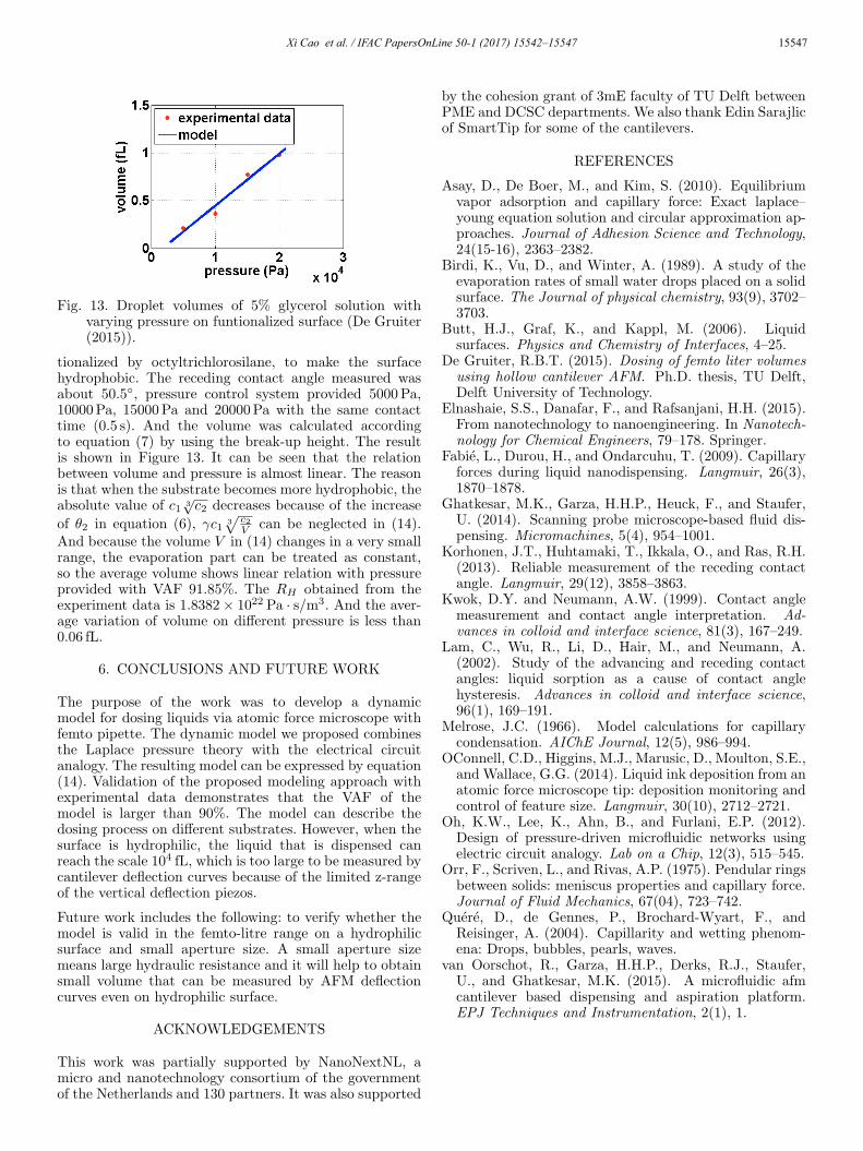
Fig. 13. Droplet volumes of 5% glycerol solution withvarying pressure on funtionalized surface (De Gruiter(2015)).
tionalized by octyltrichlorosilane, to make the surfacehydrophobic. The receding contact angle measured wasabout 50.5◦, pressure control system provided 5000Pa,10000Pa, 15000Pa and 20000Pa with the same contacttime (0.5 s). And the volume was calculated accordingto equation (7) by using the break-up height. The resultis shown in Figure 13. It can be seen that the relationbetween volume and pressure is almost linear. The reasonis that when the substrate becomes more hydrophobic, theabsolute value of c1 3
√c2 decreases because of the increase
of θ2 in equation (6), γc1 3√
c2V can be neglected in (14).
And because the volume V in (14) changes in a very smallrange, the evaporation part can be treated as constant,so the average volume shows linear relation with pressureprovided with VAF 91.85%. The RH obtained from theexperiment data is 1.8382× 10²² Pa · s/m3. And the aver-age variation of volume on different pressure is less than0.06 fL.
6. CONCLUSIONS AND FUTURE WORK
The purpose of the work was to develop a dynamicmodel for dosing liquids via atomic force microscope withfemto pipette. The dynamic model we proposed combinesthe Laplace pressure theory with the electrical circuitanalogy. The resulting model can be expressed by equation(14). Validation of the proposed modeling approach withexperimental data demonstrates that the VAF of themodel is larger than 90%. The model can describe thedosing process on different substrates. However, when thesurface is hydrophilic, the liquid that is dispensed canreach the scale 104 fL, which is too large to be measured bycantilever deflection curves because of the limited z-rangeof the vertical deflection piezos.
Future work includes the following: to verify whether themodel is valid in the femto-litre range on a hydrophilicsurface and small aperture size. A small aperture sizemeans large hydraulic resistance and it will help to obtainsmall volume that can be measured by AFM deflectioncurves even on hydrophilic surface.
ACKNOWLEDGEMENTS
This work was partially supported by NanoNextNL, amicro and nanotechnology consortium of the governmentof the Netherlands and 130 partners. It was also supported
by the cohesion grant of 3mE faculty of TU Delft betweenPME and DCSC departments. We also thank Edin Sarajlicof SmartTip for some of the cantilevers.
REFERENCES
Asay, D., De Boer, M., and Kim, S. (2010). Equilibriumvapor adsorption and capillary force: Exact laplace–young equation solution and circular approximation ap-proaches. Journal of Adhesion Science and Technology,24(15-16), 2363–2382.
Birdi, K., Vu, D., and Winter, A. (1989). A study of theevaporation rates of small water drops placed on a solidsurface. The Journal of physical chemistry, 93(9), 3702–3703.
Butt, H.J., Graf, K., and Kappl, M. (2006). Liquidsurfaces. Physics and Chemistry of Interfaces, 4–25.
De Gruiter, R.B.T. (2015). Dosing of femto liter volumesusing hollow cantilever AFM. Ph.D. thesis, TU Delft,Delft University of Technology.
Elnashaie, S.S., Danafar, F., and Rafsanjani, H.H. (2015).From nanotechnology to nanoengineering. In Nanotech-nology for Chemical Engineers, 79–178. Springer.
Fabie, L., Durou, H., and Ondarcuhu, T. (2009). Capillaryforces during liquid nanodispensing. Langmuir, 26(3),1870–1878.
Ghatkesar, M.K., Garza, H.H.P., Heuck, F., and Staufer,U. (2014). Scanning probe microscope-based fluid dis-pensing. Micromachines, 5(4), 954–1001.
Korhonen, J.T., Huhtamaki, T., Ikkala, O., and Ras, R.H.(2013). Reliable measurement of the receding contactangle. Langmuir, 29(12), 3858–3863.
Kwok, D.Y. and Neumann, A.W. (1999). Contact anglemeasurement and contact angle interpretation. Ad-vances in colloid and interface science, 81(3), 167–249.
Lam, C., Wu, R., Li, D., Hair, M., and Neumann, A.(2002). Study of the advancing and receding contactangles: liquid sorption as a cause of contact anglehysteresis. Advances in colloid and interface science,96(1), 169–191.
Melrose, J.C. (1966). Model calculations for capillarycondensation. AIChE Journal, 12(5), 986–994.
OConnell, C.D., Higgins, M.J., Marusic, D., Moulton, S.E.,and Wallace, G.G. (2014). Liquid ink deposition from anatomic force microscope tip: deposition monitoring andcontrol of feature size. Langmuir, 30(10), 2712–2721.
Oh, K.W., Lee, K., Ahn, B., and Furlani, E.P. (2012).Design of pressure-driven microfluidic networks usingelectric circuit analogy. Lab on a Chip, 12(3), 515–545.
Orr, F., Scriven, L., and Rivas, A.P. (1975). Pendular ringsbetween solids: meniscus properties and capillary force.Journal of Fluid Mechanics, 67(04), 723–742.
Quere, D., de Gennes, P., Brochard-Wyart, F., andReisinger, A. (2004). Capillarity and wetting phenom-ena: Drops, bubbles, pearls, waves.
van Oorschot, R., Garza, H.H.P., Derks, R.J., Staufer,U., and Ghatkesar, M.K. (2015). A microfluidic afmcantilever based dispensing and aspiration platform.EPJ Techniques and Instrumentation, 2(1), 1.
Proceedings of the 20th IFAC World CongressToulouse, France, July 9-14, 2017
16117