a middleby company i
TRANSCRIPT
Ea southbend A MIDDLEBY COMPANY
IMPORTANT FOR FUTURE REFERENCE
Please complete this information and retain this manual for the life of the equipment. MODEL # SERIAL # DATE PURCHASED
i
OWNER’S MANUAL INSTALLATION USER’S GUIDE
SERVICE PARTS
INFRA-RED CHEESE MELTERS
MODELS: CM-3lC; CIU-36; CM-32; CM-S-60 CM-mPC, cNl=3lw, CMal, CM-3lP CMeoc, cM-64,cM-60=60 CNMOPC, CM4OW, CM-60, CM-6OP
These instructions should be read thoroughly before atterrpting instaMion. in&Won and Start Up should be petformd by a qualified service techridan. The Mariutacturer, Southbend (1100 Old HoneyaRt FM., Fuquay-Varina, hbrih Camfina 2Z26), infomrs you ~atunlessthe.~ninstnrctionsfortheabove~SwthbendFHodud~ ~andperformedbyaquatifisd~technician,(apelsan~encedinand krmhdgeable aweming the instalWon of cofnmefcial gas.aWof ektrkal oook@ equipment) then the terms and conditions of the Manufachner’s Limited warranty will be rendefedvoidandnowanantyofanykindshaUapply.
If the equipment has been changed, attered, modified or repaired by other than a quaiified sewice technician during or after the 12~mordh limited warranty period, then themanufadurershan~beCaMefotanyindde~orconsequentiald;unagestoany person or to any property which may result from the use of the equipment thereafter. Some States do not allow the exclusion or limitation of incidental or consequential ~~,so~e~~li~orexdusiontheretomaynot~toyou.
Intheeve~~youhaveanypuestionsconcemingtheinstal(ation,use,care,orsenriceof the pfocm, write Customer Service Department, Southbend, 1100 Old Honeycult Rd, Fuquay-Vartna, North Camha 27526.
MFRAIRED CHEESE MELTERS (Manual Section BR)

Chqmtdationa! You have jut purched me at the best piecss uf heavy-dufy, mefiial e00king equipment on the market today.
You will 5nd that your new equipment, like all Southbend equipment, has been designed and manufachaed to some of the toughest standards in the indumy - thoss of Southbend Cqmration. Each piece of Southbend equipment haa been cn~fblly engineered and de&ns have ken vsrified through laboratory m end field instabtions in some of the more strenuous commercial cooking applic&m. With proper ca,m and field maintenance, you will experience years of relisble, &mbb-&ee operation from your So&bend equipment. To get the best msul% it% important that you read tbis manual cmwfizlly.
TABTZ OF CONTENTS SE~‘.KNO.KNO~-ON
IrltdMon . . . . . . ..--.*..........................*......-.-...................
. . . . . . . . . . . . . . . . . . . . . . . ..-.-.-..........~-........................... ; SEXXONTWO-UsER’SGuIDE
. . . . . . . . ..*.....I-...............*...............*-.......~......... 192
ouredusive Schwank cfmmictilehumm in8bouth&theusualtime,withlesgas
mheatingsoccmdaryanfacesasisn~in
CA-ON: POST INZ?ROiMINENT Lt2CtUTON~S~UcIIoNS To BE FOLLOWED m !lT?E EVENT THE SMELL OF GAS IS DlZ2YZmD. Z!EIS RWO2’Ui@l7ON S&ALL BE OBT~ERO~LOCXLWSIP+~
t 1
I I
FoRYouRsAEETY
DO NOT STORE OIt USE GASOLTNE OR OTHBR-LEVAPORSAND ~QUBWINTBEVICINlTYOF’~OZUNYOTHEEtAppw[ANcE.
KEEPAREAAROUND APPLuNcBs~ANDcLEARFaoMcoMB-s.
INTHEEVENTAGASODOEISDETecTeD,~DOWN~UIfMENTA31‘THE MAIN SHUTOFF VALVE AND CONTACT TEE LOCAL GAS COMPANY OR GAS -FoR-cE9
l
WARNING-W- wIuBEvoIDIR ASERVICEWORKISPERFORMEDBYOTHERTaANAQUAL;IFIED
TlWHNICIAN. KOTKERTHANGENMNE souTHBENDBlEPLA~ PAaTs ARE
INSTALLED.
1lOOOklHOMyCiJItROild Fquay.NC27526 (919)662-9161 FAX(919)552-9796

INFRA-RED CHEESE MELTERS INSTALLATION SPECIFICATIONS mj
COUNTER UNITS
DIMENSIONS:
FRONT VEW END VIEW END VIEW FRONTVIEW
ClFn&CS3lP cNbOacN-6w (Upper gas connection not mfaitablc on W-31P tk chbmop~
I”i--l
RLiJ CM-3lC&CM-3lPC
(Upper gas comeion not mdable on C%3lPC &
(In Inches)
t . YooEL9 1 NElGHr
CM-31 31 16 19% @.w 16 19% CMMP 31 ?4’/$ 19% CM6OP w2 14’h 19% CMCMC
INFRA-REO CHEESE MEUERS SEC’IION ONE - lNSlALLA3lON
PAGE 1

I INSTALLATION
I WARNING: THESE PROCEDURES MUST BE FOLLOWED BY QUALIFIED PERSONNEL OR WARRANTY WILL BE VOIDED. I
THE UNiT, WHEN INS’T%LLXD, MUSI’ CONFORM WITH LOCAL CODES, OR IN THE ABSENCE OF LOCAL CODES, WITH THE NATIONAL FUEL MS CODE, ANSI 2!2!23.1-Latest Edition. CANADIAN INSTALLATION MUST COMPLY WITH CAN/CGA-B149.1 NATURAL GAS INSTALLATION CODE, CODE CAN/CGA-B149.2 PROPANE INSTALLATION CODE. Serial plate located on the top of the unit at the hnt towards the right, indicates the type of gas your unit is equipped to burn, Do Not connect to any other gas type. These models are design certified for operation on Natural or Propane gases.
ORIFICECHART
Total Burner pilot Pressure Gas Rating orifice Olifie Bllnler Regulator
NCitllId 25,000 BTU/Hr. No. 44 (P-N. 3 166904) -016 (P-N. 1163675) universal 6” W.C. Propane 25,000 BTU/I+. No. 53 (P.N. 1163653) ,016 (P.N. 1163676) universal lo” WC.
NOTE: If this equipmeat is king installed over 2,000 feet altitude and was not so specified on order, contact Swthbend Service DepartmenL Failure to install with proper orifice sizing may ‘void the warranty.
SUFFlX DEFlNITiONS PRERX DEFINITIONS
CM: CheeseMelter P: PassThrough
PC : Pass Though Counter Unit c : collnter units
W : Wall Mount Units
3: Single Units Input 25,000 BTUH
6: Double Units Input 50,000 BTUH
.
INSTALLATION CLEARANCES, AS APPLICABLE.
MINIMUM CLEARANCES FROM COMBUSTIBLE CONSTRUCTION
Side-6INCHES BACK - 0 INCHES (Bottom Gas Connection) BACK-6 INCHES (Rear Gas Connection)
I A 12” clearance above the top of the broiler is required for proper venting and service. I
PASS THRU DESIGNS (Models CM3IPC and CM-6OPC) should be accessible from both front and back, and must NOT BE LOCATED CLOSER THAN TWENTY-TWO (22) INCHES at back or front to any combustion constructions. Never attach pass rhru unit directly to a wall.
I Counter Models (CM-31C AND CM31PC, CM -6OC AND CM4OCP)
For use only on noncombustible counters. I
NOTICE: The unit must be installed in such a manner that the flow of combustion and ventilation air are not OBSTRUCTED. An adequate air supply for combustion is obtained thm a series of holes at the top of the unit. These openings must NOT be OBST?WXED in any way while the unit is operating. The unit must be accessible for service.
t
IWRA-WDCHEESEMELTERS SECTION ONE-INSTALLATION PAGE 4
lithoin USA 11-92

INSTALLATION
NOTE: No additional clearance from the sides and back is required for service, as the units are serviceable from the front.
E2iHAUST FANSAND CANOPIES: Canopies are set over ranges, ovens, etc., for ventilation purposes. It is recommended that a canopy extend 6” past appliance and be located 6’6” from the floor. Filters should be installed at an angle of 45 degrees or more with the horizontal. This position prevents dripping of grease and facilitates collecting the run-off grease in a drip pan, usually installed with a filter. A strong exhaust fan tends to create a vacuum in the room and may interfere with burner performance or may extinguish pilot flames. Fresh air openings approximately equal to the fan area will relieve such vacuum. In case of unsatisfactory perf ormance on an appliance, check with the exhaust fan in the “OFE” position.
NOTE: Be sure to inspect and clean ventilation system according to the ventilation equipment manufacturerk instructions.
I WARNING: THESE PROCEDURES MUST BE FOLLOWED BY QUALIFIED PERSONNELORWARRANTY WIUBEVOIDED.
GAS CONNECTIOM l.AtX&i.fied pressme regulator designed for the type of gas for which the unit is equipped is packed
with the unit.
2. If applicable, the vent line from the gas appliance pressure regulator shall be installed to the outdoors in accordance with local codes or, in the absence of local codes, with the National Fuel Gas Code, ANSI Z223.1-Latest Edition. Canadian installation must comply with CANXGA- B149.1 Natural Gas Instahation Code, Code CAN/CGA-B1492 Propane Installation Code.
3. The gas supply connection is l/2” NIT and can be made at either the rear or the bottom on the left-hand side. Both of these connections are closed by a l/2” NPl’ plug as shipped from the factory. Pass thru models only have bottom connection. AREA&
Bemove the 1/2” NPT plug at the rear lefi side. Insert a V2” NPT nipple, 3 inches long, into this fitting. At the inlet of this I.&!” NPT nipple install the pressure regulator. Take care that the flow of gas thru this pressure regulator is as indicated by an axrow on this controL Install a 1/2”NPTserviceshutoffvalvetotheregulatorandcoMecta1/2”NPTgassupplylinetothis valve.
B. BO’ITOE Remove the l/2” NPT plug at the bottom lefi area and use the same pmcedure as above for the connection.
I CAUTIONBESURETOHOLDPRESSUREREGULAZ#RWIZHAWRENCH~Z7GHlENLNG SUPPLYPIPEToAVOIDDAMAGEToTIEEREGULA7UR,VvALvE,ANDO7HERCOMPONENZS. I
4.TheunitshouId13econnected~ytothetypeofgasfarwhichitisequipped.Checktypeof~on rating plate. On all threaded connections, the pipe compound must be approved for use with natural and propane gas.
5. Make sure burner valve is in the ‘Ol?F’ position before connecting gas to unit. Test all pipe connections thoroughly for gas leaks. Use soapy water only for testing on all gases.
6. Turn on burners and bleed supply line, then turn burners off.
7. Light pilot and adjust so that flame is approximately W8" long. Adjustment is tbru a 318” dia. 0ueni.w in the white area of the valve indicator decal.
I --- ---- -- --- --- --- -~~ - SUPPLYPrPINGSYSllEMAT~STP~SSURES~UAL~O~LESS~1/2PSIG(3.45KPa). 1
wFRA4?EDaEEsEMELlERs SEmONE-iNSTALL4TlON
PAGE 3
\
INSTALLBTION
ST&EB;;~LmOm~D BY QUALIFIED .
A I” NPT line is provided at the rear for the connection. Each unit is equipped with an internal pressure regulator which is set for 4” WC. manifold pressure for natural gas and 10” WC. for propane gas. Use 1/8” pipe tap on the burner manifold for checking pressure.
An adequate gas supply is imperative. Undersized or low pressure lines will restrict the vohrme of gas requked for satisfactory perhonnauce. A steady supply pressure, 6” W.C. for natural gas aud 10” W.C. for propane gas, is recommended. With all uuits operating simultaneously, the manifold pressure on all units should not show any appreciable drop. Fluctuations of more than 25% on natural gas, and 10% on propane gas, will create pilot problems and affect burner operating characteristics. Contact your gas company for correct supply line sizes.
Purge the supply line to clean out any dust, dirt, or other foreign matter before connecting the line to the unit. It is recommended that an individual manual shutoff valve be installed in the gas supply line to the unit. Use pipe joint compound which is suitable for use with LP gas on all threaded connections. Test pipe connectious thoroughly for gas leaks. USE SOAPY WATER ONLY FOR TESTING ON ALL GASES. NEVER USE AN OPEN FLAME TO CHECK FOR GAS LEAKS. ALL CONNECTIONS MUST BE CHECKED FOR IEAKS, AFTER TIIE UNIT HAS BEEN PUT IN OPERATION.
lNPRAaEDcNEEsEMELTERs SECTION ONE-INSTALLATION
PAGE 4

INSTALLATION r
I WARNING: THESE PROCEDURES MUST BE FOLLOWED BY QUALIFIED PERSONNELORWARRANTY WILL BE VOIDED. I
All Cheese Melters are shipped with rack guide assemblies packaged in the crate. They are easily assembled to each side as shown above. Rack guides should be removed periodically for cleaning.
FIELD ASSEMBLY INSTRUCTIONS AND DIAGBAMS The following section covers Field Assembly installation instructions for the Cheese Melter unit combinations noted below and shown on SECTION ONE, page 3.
1. Installing legs for counter units. Model Numbers CM-31C and CM-31PC . . . . ..*...-.................... SECTION ONE, Page 7
2. Assembliug wall mount hanger and attaching unit for wall mount units. Model No. CM-31W . . . . . . . . . . . . . . . . . . . . . . . . . . . . . . . . . . . . . . . . . . . . . . . . . . . . SECTION ONE, Page 8
3. Assembling flue risers and attaching unit for mounting over 32 in. Sectional Range. Model No. CM-32 . . . . . . . . . . . . . . . . . . . ..-........................... SECTION ONE, Pages 9,10
4. Assembling flue riser and attaching unit for mounting over 36 in. Cafe Range. Model No. CM-36 . . . . . . . . . . . . . . . . . . . . . . . . . . . . . . . . . . . . . . . . . . . . . SECTION ONE, Pages 11,X& 13
5. Assembling flue riser and attaching unit for mounting over 60 % in. Cafe Range. Model No. CM-3160 . . . ..I............................................. SECTION ONE, Page 20
INSTRUCI’IONS: To Install Legs on Counter Models 1. Remove the BASIC Unit from the container.
2. CAREFULLY place the unit on its BACK.
3. Four NSF approved LEGS are packed with the unit.
4. REl? sketcllbelow Atbreaded~CEPTACLE(R),isattacbedtothe underside oftbe bottom, at each comer. Each leg has a threaded STUD (S). ‘I?ghtentbestudoneachlegintoareceptace.Secure with a wrench on the hexagon section of the leg. Each leg has its own NSF approved leveling FOOT (LX By adjust&these feet, the proper combination can be achieved whereby the unit will be level and steady.
Never attach the pass thru unit, Model CM3lP, Directly to a wall.
1NmA-REDcHEEsEMELlERs SECTIONONE-INSTALLA=
PAGE 5

\
INSTALLATION
1.
2.
3.
4.
5.
6.
7.
MODEL NO. CM31W
DIAGRAM FOR MOUNTING CHEESE MELTER TO WALL USING CM-W-31 WALL MOUNT KIT.
%
A- l/4” -20 x l/2” Hex head Sol. P/N 1146200 with Split Washer P/N 1146500
and l/4” -20 Hex Nut P/N 1146400
C - #10x 112” Sloted Truss Head Sheet Metal Screw PIN 1146300
Wall mouut consists of the following parts:
A. (1) Top Bracket - T B. (1) Bottom Bracket - B C. (1) Right Side Bracket - R D. (1) Left Side Bracket - L E. (1) Right Filler - FR F. WLeft Filler-FL G. Necessary Fasteners
NOTE: Fasteners for mounting bracket zttssembly to wall are not provided.
Determine method of gas piping, remove pipe plug from unit and if piping fkom the rear, add ===wfittings.
Assemble T, B, L and R as showu. Twill hook into the mounting pocket located at the rear of the unit. B should be positioned so that the bottom flange is flush with the unit bottom when lllOunted.
Mount wall mount assembly securely to the wall in the desired location.
Liftunit andplace~eonTiato~partafrearmountingpocket.Positionunit as desired fromrighttoleftalld secure bottom of unit through slots in horizontal flange ufB through CL
Rocf3ed with gas connections as discus& in the forward section of this mauual.
INFRARED CHEESE MELTERS SECIION ONE - INsTc\LLATIoN

INSTALLATION I
WARNING: FOR AN APPLIANCE EQUIPPED WITH CASTERS, TRE INSTALTXf’ION SHALL BE MADE WITB A CONNECTOR TEIAT COMPLIES WITH TEE STANDARD FOR CONNECTORS FOR MOVABLE GAS APPLIANCES, ANSI 221.69-198‘7, CAN/CGA-6.16. MS7 AND A QUlCX-DISCONNECT DEVICE THAT COMPLIES WITH THE STANDARD FOR QUICK-DISCONNECT DEVICES FOR USE WITH GAS FUEL, ANSI 221.41-1978, AND ADDENDA, Z21.41a-1981, ZZ1.41b-1983 AND CAN1 6.9 M79. ADEQUATE MEANS MUST BE PROVIDED TO IJMXT THE MOVEMENT OF THE APPLJANCE WITHOUT DEPENDING ON THE CONNECTOR AND THE QUICK-DISCONNECT DEVICE OR ITS ASSOCIATEDPIPlNGTOIJMITTFIEAPPLL4NCEMOVEMENT.
~iJlI?+I&ISCO.~~ON OF THIS REJ STRAINT Is NECESSARY To REMOVE CIZANING, EYI’C, RECONNECT IT WHEB TEIE APPIJANCE IS
MOVED TO ITS ORIGINALLY INSTALLED POSITION.
MODEL NO. CM-32
DIAGM FOR MOUNTING CMS-32SECTIONAL32IN.RzsERTORANGE,
1. Front panel “A” is fastened with (4) hex head sheet metal screws. Remove screws and panel.
2. Remove nuts and lockwasher f+om collar plate studs “C” on range.
3. Lower riser onto range allowing studs “C” to enter holes in riser bracket ‘EV Secure riser bracket %= with nuts and lockwasher removed in instru~on No. 2.
4. Install angles W packaged in riser container with slotted hez head screws provided, into holes in rear riser bracket ‘W and match drill 964 inch dia. holes in range body for mounting angle “IT to range with slotted hex head screws provided.
5. Install unit (see instnlctioIls).
6. F&place fkont panel uA” and fasten with sheet metal screws that were removed in in&r&ion No. 1.
7. U-shaped channel ‘G” is provided for all batteried ranges. Place U&aped channel ‘G” over angles on adjacent ranges to form a sanitary sealing between ranges.
iNFRA-i?EDCHEESEMELTERS sEcnoNoNE-lNsTALLAnoN
PAGE 7

INSTALLATION
MODEL NO. CM-32
DIAGRAM FOR MOUNTING CHEESE MELTER TO 32 IN. SECTIONAL RANGE RJSER NO. CMS-32,
1. Determine method of gas piping and remove pipe plug fkom unit.
2. Hanger bracket “B” is attached to unit sA” at the &tory unless ordered otherwise.
3. Lift unit with hanger bracket attached and place banger over riser support “c” and fasten with (3) slotted hex head sheet metal screws.
4. Fasten bottom back of unit to the riser with the two bottom hold brackets “D” provided. A magnetic screwdriver should be used. Bottom hold brackets (P/N 1163736) are to be secured to the inner riser uprights through the two prwlrilled holes in the back of the uniti
5.proceedwithgaswnnectiansasdiscussedinthefo~sectionofthismanual.
NOTE: Range clearances to combustible con&n&ion, as shown on range serial plate, supersede Cheese Melter clearances.
INFRA-REDCHEESEMELTEFS SECTlON ONE- WSTALLAllON T%Y - PAGE 8

INSTALLATION r
WARNING FORANAPPUANCE EQUIP= WlTE CASTERS, TEE INSTWTION SHALLBEMADEWITHACONNECTORTHATCOMPIJES WlTHTEESI!!ARDFOR CONNECTORS FOR MOVABLE GAS APPIJANCES, ANSI 221.69-1987, CAN/CGA-6.16- MI37 AND A QUICK-DISCONNECI’ DEVICE TEAT COMPLlEX3 WITH THE WANDARD FOR QUICK-DISCONNECT DEVICES FOR USE WIl’!E GAS FUEL, ANSI 221.41-1978, AND ADDEND& 221Ala-1981,221.41b-1983 AND CAN1 6.9 M79. ADEQUATE MEANS MUST BE PROVIDED TO LIMIT THE MOVEMENT OF TEE APPLIANCE WITHOUT DEPENDING ON TBE CO~CTOR AND TEiE QUICK-DISCONNECT DEVICE OR ITS ASSOCIATEDPIPINGTOLIMITTEIEAPPLLWcEMOVEMENT.
WARNING: IJ? DISCONNECTION OF TEIS RESTRAINT Is NEcIEssARY TOREMOVE THE APPIJANCE FOR CLEANING,EI’C,RECONNECT~WHENTBEAPPIJANCEIS MOVEDTOITSORIGINAU,YINSTALLEDPOSITION.
MODEL NO. CM=36
DIAGRAIKFORMOUNTING CMCX6 CAFE 36 IN. RISER TO RANGE.
1. Rear Panel *A” is fastened far shipping with (4) hex head sheet metal screws. Remove screws and rear panel,
2. Set the two angles T’ aside until Cheese Melter is mounted.
3. Lower riser onto range, line up holes in riser bracket “B” with weld nut holes in range. Secure riser bracket ‘W’ to range witb (4) hex head l/4-20 screws and (4) washers (2 each side) provided.
4. The oven flue riser extension T” is packed in oven. Slide fiue riser extension 7.7 t&rough hole in rear rest “IIn over collar protruding tbrougb burner box bottom YE.”
5. Install unit bee instnlctions).
WFFiA-REDCHEESEMELTERS sEclloNoNE-!lNsTAuATloN
PAGE 9

\
1.
2.
3.
4.
5.
INSTALLATION
MODEL NO. CM36
DIAGRAM FOR MOUNTING CHEESE MELTER To 36 IN. CAFE RANGE RISER.
Determine method of gas piping and remove pipe plug from unit.
Hanger bracket “B” is attached to unit at the factory unless ordered otherwise.
Lift unit with hanger bracket attached and place hanger over riser support “C and fasten with (3) slotted hex head sheet metal screws. Unit should be centered on riser.
FastenbottombaclrofunittotheFiserwiththetwosheet metalscrewssecuredintopredrilled holesintheb~oftheunitthroughrearofriser.
Install rear panel “A” and angles “‘I”’ to rear of riser assembly (see instructions). Match drill 9164 dia. holes in range body for mounting angle 9” to range at the bottom.
NOTE: Range clearances to combustible cons&u&ion, as shown on range serial plate, super&e Cheese Melter clearances.
lNPRA=NEDcNEEsEMEuEFls SECTION ONE - INsTAuATlON
INSTALLATION t
MODEL NO. CM36
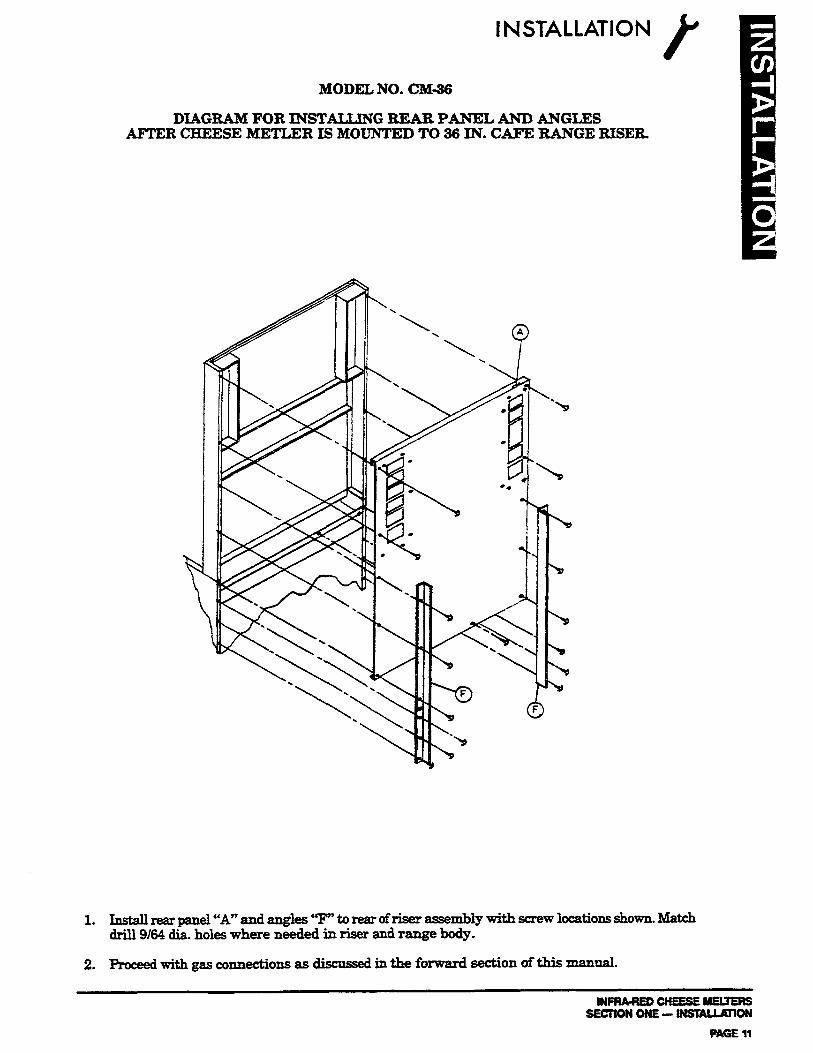
DIAGRAM FOR INSTALUl4G REAR PANEL AND ANGLES AFlXR CHEESE METLER IS MOUNTED TO 36 IN. CAFE RANGE RISER.
1. Install rear panel “A” and an&s ‘T” to rear ofriser assembly with screw locations shown. Match drill 9164 dia. holes where needed in riser and range body.
2. Proceed with gas connections as discus& in the forward section of this manual.
INFfWREDCHEESEMEUERS SIWION ONE- lNSKALLKllON

I INSTALLATION
FIELD ASSEMBLY INSTRUCZ’IONS AND DIAGRAMS
The following section covers Field &sembly in&al&ion instructions for the Cheese Melter unit com- binations noted below and shown on SECTION I, page 3.
1. Installing legs for counter units. Model Numbers CM-GOC and CM-GOPC SECTION I, page 14
2. Assembling wall mount hanger and attaching unit for wall mount units. Model No. CM-GOW . . . . . . . . . . . . . . . . . . . . . . . . . . . . . . . . . . . . . . . . . . .SECTIONI, page 15
3. Assembling flue riaors and attaching unit for mounting over two 64 in. Sectional Ranges. Model No. CM-64 . . . . . . . . . . . . . . . . . . . . . . . . . . . . . . . . . . . . . . . . .SECTION I, pages 16, 17
4. Assembling flue risor and attaching unit for mounting over 60-314 in. Cafe Range. Model No. CM-60-60. . . . . . . . . . . . . . . . . . w . . . . . . . . . . . . . . . . . . . -SECTION I, pages 18,19
MODELS CM-6OC AND CM-PC
INSTRUCTIONS: To instaII Legs on Counter Models
1. Remove the BASIC Unit from the container. CAUTION: C~CKTOlNSVRE THAT THESCREWS, WHICHHOLD =BURNER
I.N PLACE DURING SILlPPmG, ARE STILL SECURlNG IT.
2. CAREFULLY place the unit on its BACK.
3. Four NSF approved LEGS are packed with the unit.
4. REFz Sketch below:
A threaded RECEPTACLE CR), is attached to the underside of the bottom, at each comer.
Each leg has a threaded STUD Q.
Tighten the stud on each leg into a receptacle. Secure with a wrench on the hexagon section of the leg.
Each leg has its owp NSF approved leveling FOOT (L). By ad.. these feet, the proper combination can be achieved whereby the unit will be level and steady.
CAUTION: ONLYNON~OMBU co-AREmBEusEDmsuPmm~ lIlM!ls.. ~~~OMooMBUslzBLE~U~ONsHow1vONPAGE2.
NEVER attach the pass tbru unit, Model CM-GOP, directly to a wall.
WFRA-RED CHEESE MELTERS SECTIONONE-lNSTALUllON PAGE 12

1.
2.
3.
4.
5.
6.
7.
INSTALLATION
MODEL NO. CM&oW
DIAGRAM FOR MOUNTING CHEESE MELTER TO WALL USING CMWa WALL MOUNT EXT.
Wall mount consists of the following parts:
A. (1) Top Bracket - T B. (1) Bottom Bracket - B C. (1) Right Side Bracket - B D. (1) Left Side Bracket - L E. (1) Right Filler - FR F.WLeft.Filler-FL G. Necessary Fasteners
NOTE Fasteners for mounting bracket assembly to wall are not provided.
Determine method of gas piping, remove pipe plug from unit and if piping from the rear, add necessargfittings.
Fasten FR and FL to each side of unit by removing upper and lower rear body side screws and *attach with fillers in place.
Assemble T, B, L and R as shown. T will hook into the mounting pocket located at the rear of the unit. B should be positioned so that the bottom flange is flush with the unit bottom when mounted.
Mount wall mount assembly securely to the wall in the desired location.
Lift unit and place flange on T into upper part of rear mounting pocket. Position unit as desired from right to left and secure bottom of unit through slots in horizontal flange of B through CL
proceed with gas ccmmctions as discus& in the forward section of this manual.
lrmuaEDcNEEsEMEuENs SECTION ONE-INSlUJJlON
PAGE13
1 INSTALLATION
WARNING FOR AN APPIlLGNcE EQUIPPED WITH CASTERS, THE INSTALLATION SHALT., BE MADE WITH A CONNECTOR TEAT COMPLIES WITH THE STANDARD FOR CONNECTORS FOR MOVABI;E GAS APPLIANCES, ANSI 221.69-1937, CAN/CGA- 6.16-MS7 AND A QUICK-DISCONNECT DEVICE THAT COMPLIES WITH THE STANDARD FOR QUICK-DI!XONNECT DEVICES FOR USE WlTH GAS FUEL, ANSI 221.41-1978, AND ADDENDA, 221.41a-1981, Z21.41b-1983 AND CAN1 6.9 M79. ADEQUATE MEANS MUST BE PROVIDED TO LIMIT THE MOVEMENT OF THE APPLIANCE WITHOUT DEPENDING ON THE CONNECTOR AND THE QUICK- DISCONNECT DEVICE OR ITS ASSOCIATED PIPING TO LIMIT THE APPLIANCE MOVEMENT.
WAR&IN& IF DISCONNECTION OF THIS RESTRAINT Is NECESSARY To REMOVE TBE APPLTANCE FOR tXZANlNG, E’IC, RECONNECT IT WHEN THE APPLIANCE IS MOVED TO ITS ORIGINALLY INSTALLED POSITJON.
MODEL NO. CM-64
DIAG.&iMFORIKOUNTING cMs-64sEcTIoNAL64lN.RI8ERToTwoRANGEs
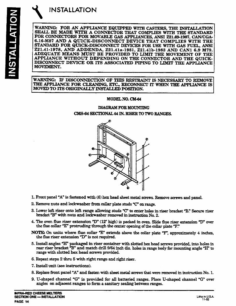
1. F’ront panel “A” is fastened witb (6) hex head sheet metal screws. Remove screws and paneL
2. Remove nuts and lockwasher fkom collar plate studs T’ on range.
3. Lower left riser onto lefk range allowing studs ‘C to enter holes in riser bracket ‘B.” Secure riser bracket “B” with nuts and lockwaaher removed in instruction No. 2.
4. The oven flue riser extension “D” (12” high) is packed in oven. mde flue riser extension “I)” over the flue collar T protruding through the center opening of the collar plate T.=
NOTE: On units where flue collar T’ extends above the collar plate T’, approximately 4 inches, the flue riser extension UD” is not required.
5. Install angles w” packaged in riser container with slotted hex head screws pn>vided, into holes in rear riser bracket 3” and match drill 9164 inch dia. holes in range body for mounting angle “H” to range with slotted hex head screws provided.
6. Repeat steps 2 thru 5 with right range and right riser.
7. Install unit (see instnlctions).
8. Replace front panel “A” and fasten with sheet metal screws that were removed in iu&uction No. 1.
9. U-shaped channel “G” is provided for all battexied ranges. Place U-shaped channel ‘G” over angles on adjacent ranges to form a sanitary sealing between ranges.
INFRA-REDCHEESEMELTERS SECTlOHOHE-IHSTALLATiOH PAGE 14
litho in U.SA 11-92

INSTALLATION r
MODEL NO. CM&$
DIAGRAM FOR MOUNTING CHEESE MELTER TO 64 IN. SECTIONAL RANGE RISER NO. CMS-64.
1. Determine method of gas piping and remove pipe plug from unit.
2. Hanger brackets “B” are attached to unit ‘A” at the factoq unless ordered otherwise.
3. LiR unit witi banger brackets attached and place hangers over riser support “Cy line up holes and fasten with (6) slotted hex head sheet metal screws.
4. Fasten bottom of unit to the center uprights using bracket ‘p,t and match drill 9164 in. dia. holes, two in uprights and one in bottom of unit. Fasten with (3) sheet metal screws provided.
5. Proceed with gas connections as discus& in the forward section of this manual.
NOTE: Range clearances to combustible constmction, as shown on range serial plate, supersede Cheese Melter clearances.
INPNA-NED CNEESE hELtENS SECnON ONE - INSULLUION
PAGE 15

I INSTALLATION
WARNING FORANAPPLIANCE EQUtPPED WITTI CASTERS, THE INST~TION SHALL BE MADE WITH A CONNECTOR THAT COMPLIES WITH THE STANDARD FOR CONNECTORS FOR MOVABLE GAS APPLIANCES, ANSI 221.69-1987, CAN/CGA- 6.16-MS7 AND A QUICK-DISCONNECT DEVICE THAT COMPLIES WITH THE STANDABD FOR QUICK-DISCONNECT DEVICES FOR USE WITH GAS FUEL, ANSI 221.41-1978, AND ADDENDA, 221.41a-1981, 221.41b-1983 AND CAN1 6.9 M79. ADEQUATE MEANS MUST BE PROVIDED TO LIMIT THE MOVEMENT OF TH.E APPLIANCE WITHOUT DEPENDING ON THE CONNECTOR AND THE QUICK- DISCONNECT DEVICE OR ITS ASSOCLATED PIPING TO LIMXT THE APPLIANCE MOVEMENT.
WARNING IF DISCONNECTION OF THIS RESTRAINT Is NECESSARY To BEMOVE THEAPPLk3NCEFOR CLEANING, El-C., RECONNECT IT WHEN THE APPLIANCE IS MOVED To ITS OBIGINALLY YNSTATXXD POSITION.
MODELNO. CM&60
DIAGR&IFORMOUN’lJNG ClKS=6OCAFE6OlN..TORANBANGE.
1. Rear Panel “A” is fastened for sbipping with (4) hex head sheet metal screws. Remove screws and rear panel.
2. Set the (3) angles “E” aside.
3. Lower riser onto range, line up holes in riser “A” with weld nut holes in range. Secure riser “A” to range with (4) hex head M-20 screws and (4) washers (2 each side) provided.
4. The oven flue riser extensions “B” are packed in oven. Slide flue riser extensions ‘W through hole in rear rest “CT’ over collar protrucling through burner box bottom “II.”
5. Install unit (see instrllctions).
INFRA-REDCHEESEMELTERS SECTION ONE- 1NSTALLATlON PAGE 16

MODEL NO. CM-6@60
DIAGRAM FOR MOUNTING CHEESE MELTER TO 60-314 IN. CAFE RANGE RISER NO. CMCXo.
NOTE: Most 60-314 * riser assemblies are shipped &om the factory preassembled to the range. If not however, follow the mounting method depicted in the diagram The following in&n&ions should then be followed to mount a Cheese Melter to a CMG60,60-3/4 ” riser assembly.
1. Determine method of gas piping and remove pipe plug from unit.
2. Hanger brackets “B” are attached to unit “A” at the f&tory unless ordered otherwise.
3. Lift unit with hanger brackets attached and place hangers over riser support at top. Line up holes and fasten with (6) slotted hex head sheet metal screws.
4. Fasten bottom back of unit to the riser with two sheet metal screws ‘9” provided. A magnetic screwdriver should be used.
5. Roceed with gas connections as discussed in the forward section of this manual.
6. Install rear panel ‘9” and angles “E” to rear of riser assembly. Match drill 9/64 in. dia. holes in range and riser for mounting angles.
NO!I’E: Range clearances to combustible construction, as shown on range serial plate, supersede Cheese Melter clearances.
INRU-REDCHEESEMEUEF& SECTIONONE--ON
MGEn

\
INSTALLATION
WARNING FORANAPPLIANCE EQUIPPED WITH CASTERS, THE INSTALLA~ON SHALL BE MADE WITH A CONNECTOR THAT COMPLIES WITH THE STANDARD FOR CONNECTORS FOR MOVAEIZ GAS APPIZANCES, ANSI 221.69-1987, CAN/CGA- 6.16-MS7 AND A QUICK-DISCONNECT DEVICE THAT COMPLIES WITH THE STANDARD FOR QUICK-DISCONNECT DEVlCES FOR USE WITH GAS FUEL, ANSI 221.41-1978, AND ADDENDA, 221.41a-1981, 221. 4133-1983 AND CAN1 6.9 M79. ADEQUATE MEANS MUST BE PROVIDED TO LIMIT THE MOVEMENT OF THE APPLblNCE WITHOUT DEPENDING ON THE CONNECTOR AND THE QUICK- DISCONNECT DEVICE OR ITS ASSOCIATED PIPING TO LIMIT THE APPLIANCE MOVEMENT.
WARNING: IF DISCONNECTION OF T[lBIs ZtEsTRAINT Is NECESSARY To REMOVE THE APPLTANCE FOR CLEANING, ETC., RECONNECT IT WHEN THE APPLIANCE IS MOVED TO ITS ORXGlNALLY IWTALLED POSITION.
MODEL NO. CM-31.60
DIAGRAB5FORMOUNTINGCEERSEMELTERTO 6@3/4 IN. CAFE RANGE RISER NO. MRK-30.
NOTE: Most 60-3/4” riser assemblies are shipped from the factory preassembled to the range. Ifnot however, foIlow the mounting method depicted in the diagram. The following instructions should then be followed to mount a Cheese Melter to a MRK-30,60-3/4” riser assembly.
1. Determine method of gas piping and remove pipe plug from unit.
2. Hanger bracket “B” is attached to unit “A” at the factory unless ordered otherwise.
3. Lift unit with hanger bracket attached and place hanger over riser support at top. Line up holes and fasten with (3) slotted hex head sheet metal screws. Unit should be flush against shelf.
4. Fasten bottom back of unit to the riser with two bottom hold brackets “c” provided. A magnetic screwdriver should be used. Bottom hold brackets (P/N 1163736) are to be secured to izmer riser uprights through the two pre-drilled holes in the back of the unit.
5. Proceed with gas connections as discussed in the forward section of this manual.
NOTE: Range clearances to combustible con&n&ion, as shown on range serial plate, supersede Cheese Melter clearances.
lNFRh-REDCNEESEMELTEFlS SECTION ONE- INSlALLATlON PAGE $8
““l%iSA

INFRA-RED CHEESE MELTERS USER’S GUIDE
LIMITED WARRANTY
Southbend wanants that the equipment, as supplied by the factory to the original purchasers, is free from defects in materials and workmanship. Should any part thereof become defective as a result of nomral use within the period and limits defined below, then at the option of Southbend such parts will be repaired or replaced by Southbend or its Autho- rized Service Agency. This warranty is subject to the following conditions: If upon inspection by Southbend or its Authorized Senrice Agency it is determined that this equipment has not been used in an appropriate manner, has been modified, has not been properly maintained, or has been subject to misuse or misapplication, neglect, abuse, accident, damage during transit or delivery, fire, flood, riot or Act of God, then this wamnty shall be void. Specifically excluded under this warranty are claims relating to installation: examples are improper utilii connections and improper utiries supply. Claims relating to normal care and maintenance are also excluded; examples are calibra- tion of controls, and adjustments to pilots and burners. Equipment failure caused by inadequate water quality is not covered under warranty. WATER QUALRY must not exceed the following limits: Total Dissolved Sol& (TDS) - 60 PPM (Parts Per Million). Hardness - 2 Grains or 35 PPM, PH Factor - 7.0 to 7.5. Water pressure 30 PSI minimum, 60 PSI maximum. Boiler maintenance is the responsibilii of the owner andisnotcoveredbywananty. This equipment is intended for commercial use only. Warranty is void if equipment is installed in other than commercial application. Repairs under this wananty are to be performed only by a Southbend Authorized Service Agency. Southbend can not be responsible for charges incurred from other than Authorized Southbend Agencies. THIS WARRANTY MUST BE SHOWN To AN AUiHORtZED SERVlCE AGENCY WHEN REQUESTING IN-VVARRANTY SERVICE WORK. THE AUTHORIZED SERVlCE AGENCY MAY Al- HIS OPTlON REQUIRE PROOF OF PURCHASE. This warranty does not cover services performed at overtime or premium labor rates nor does Southbend assume any
*iii for extended delays in replacing or repairing any items in the equipment beyond the control of Southbend. “South- nd shall not be ii for consequential or special damages of any nature that may arise in connection with such product
or part.” Should service be required at times which normally invohre overtime or premium labor rates, the owner shall be charged for the dllrence between normal service rates and such premium rats In all circumstances, a maximum of one hundred miles in travel and two and one half hours (25) travel time shall be allowable. In all oases the closest Southbend Authorized Agency must be used. The actual warranty time periods and exceptions are as follows: l%ii wananty only covers product shipped into the 48 contiguous United States and Hawaii, one year labor, one year parts effective from the date of original purchase. There will be no labor coverage for equipment located on any island not connected by roadway to the mainland. Exceptions to standard wananty, effective within above limitations: Glass Windows, Door Gaskets, Rubber Seals, Light Bulbs, Ceramic Bricks, SightGlasses,CathodicDescalersorAnodes . . . . . . . . . . . . . . . . . . . . ..-............ 90daysmaterialandlabor Stainless Steel Fry pot. . . . . . . . _ . . . . . . . . . . . . . . . .4 years extended material wananty on fry pot only - no labor Stainless Steel Open Top Burners . . . . . . . . . . . . . . . 4yearsextendedmaterialwarmntyonbumersonly-nolabor Pressure Steam Boiler Shell . . . . . . . . . . . . . . . . Prorated4yeamextendedwanantyonboilershellonly-nolabor
Boibr shells which have not been prvperiy maintained will not be coywed by warranty. InallcasespartscoveredbyafiveyearwanantywillbeshippedFOB~factMyafter~firstyear. Our warranty on all replacement parrs which are replaced in the field by our Authorized Service Agencies will be limited to three months on labor, six months on materials (parts) effective from the date of installation. See LIMITED WARRANTY - REPLACEMENT PARTS for conditions and limitations. if the equipment has been changed, altered, modified or repaired by other than a qualified service technician during or after the one year limited wananty period, then the manufacturer shall not be liable for any damages to any person or to any property which may result from the use of the equipment thereafter. “THE FOREGOING WARRANTY IS IN LIEU OF ANY AND ALL CrrHER WARRANTIES EXPRESSED OR IMPLIED INCLUDING ANY IMPLIED WARRAN-IY OF MERCHANTABlLlTY OR FITNESS, AND CONSllTUTES THE ENTlRE LIABILITY OF SOUTHBEND. IN NO EVENT DOES THE LlMlTED WARRANTY EXTEND BEYOND THE DURATION
ONE YEAR FROM THE EFFECTIVE DATE OF SAlD WARRANTY’
INPNA-FEO CHEESE YEUERS SECTION TWO - USER’S GUIDE
PAGE 1

OPERATION
CAUTIONz D’YOUSMELL GzUDlXlNG Z!KEL?GHlm?G PROCEDURE, IMMEDL4lELY SHUTOI?FTHEGASSUl=PLYU?i’TU l!l3ELEAKHAS BEENCORREC7W.
WARNNGc INTHEEVENTAGASODORISDETE~,SHUTDOWNEQ~~AT THE MAIN SFIUTOFF VALVE AND CONTACT THE LOCAL GAS COMPANY OR GAS SUPPLlERFORSERVICE
OPERATION: 1. Check that the pilot is ignited. 2. Turn burner valve to “HI1 Burner will ignite from the pilot. If burner fails to ignite, turn burner
OFF, check pilot.
CAUTION: THESE ARE NOT SAFETY PILOTS AND WmN Om, THEY DO NOT INTERBUPT THE FLOW OF GAS TO THE BURNER; CONSEQUENTLY IT IS THE RESPONSIBILITY OF THE OPERATOR To CHECK THE IGNITION OF THE BURNERS, IMMEDUTELYAF!lER THE BURNER VALVE IUS BEEN TURNED ON. SHOULD IGNITION FAlL AFTER 5 SECONDS, TURN VALVE OFF AND WtiT 5 MINUTES BEFORE TRYING AGAIN
The pilot should burn continuously unless the unit is to be completely shut down. When extinguished, the pilot gas supply is NOT INTERRUPTED automatically. For complete shutdown, the manual service value on the inlet gas supply line should be turned to OFF.
3. When the burner ignites, a blue haze type flame will cover the surface of the ceramics for 60 seconds. This haze will gradually disappear and witbin two minutes the ceramics will glow red. The flame on the surface of the ceramics should be barely visible, with practically no blue haze.
4. LOW SSEITING: After the burner has operated on HIGH for several minutes, turn the valve counterclti, as far as possible, so its handle points to the LO mark also indicated by the pink area on the colored decal hehind the valve handle. At this low setting the surface of the ceramics should become a very dull red, with a-blue haze. The burner should not %utter” or ‘pop” at this setting. If such a condition does exist, the setting is too low and should he increased. Regulation of this low setting is by a set-screw inside the hollow stem of the valve. Turn IN or clockwise to reduce and OUT or counterclockwise to increase. BURNER CONTROL: There are two de&rite positions on the burner valve, one at HI and the other at LG. Behind the valve handle, there is a colored decal. When the handle points toward the RED area, the burner is atHIGH. At LGW, the handle points to the PINKarea. Between these settings, there is a graduated colored area By placing the valve handle toward this area, a variety of burner rates can be obtained. RACE POSITION: There are two locations for the rack, due to the two sets of rack slides. To change the rack, lift and pull it forward. Then place it on the other set of slides, or on the bottom. The temperatures on this rack can thereby be changed by placing it closer or further from the burner. By the combination of rack positions and selection of burner rates, a variety of rack temperatures, suitable for i:Lpzduct being processed, can be f
All Cheese Melters are shipped with xack guide assemblies packaged in the crate. They are easily assembled to each side as shown above. Rack guides should be removed periodically for cleaning. PRODUCTS Toasting, top hmwning of numerous products such as meringue, hash browning of potatoes and other vegetables, all types of cheese melting and cheese bubbling such as on &Iexicanfoodplattem. For products other thau the dry type such as toast, a dish or a pan with adequate provisions for catching any drippings or other residue which could fall through the rack must be provided. S’hoult3 any such grease drippings or other residue fall onto the bottom, it must be removed and &aned thoroughly immediately and not allowed to accumulate.
lNFRA-f3EDCHEESEMEL~~ SECTlON TWO - USER’S GUIDE PAGE 2
Limo in USA 11-92

MAINTENANCE 1
BURNERREMOVAL:
1. Remove 12 slotted hex head screws fi-om top panel. 2. Remove top panel. 3. Disconuect gas supply tube to burner. 4. Remove tube. 5. Remove 2 screws from small filler panel at left end of burner. 6. Remove panel and insulatior~ 7. Remove 2 screws holding panel just bebind burner. 8. Remove panel. 9. Remove control knob.
10. Remove 8 slotted truss head screws fkom front panel. 11. Remove panel. 12. Remove 2 screws holding panel just in fkont of burner (pilot is mounted to t&is panel). 13. Lift up panel to disengage pilot from its entrance hole and remove panel. 14. Slide burner to the right and lift out at left end. 15. Reverse procedure to re-sssemble.
WFF&REDCHEESEMEUEFiS SECI’ION lW0 - USER’S GUIDE
PAGE 3

)) MAINTENANCE
WARNING: AJMUSTMEN’B AND SERVICE WORK MAY BE PERFORMED ONLY BY A QU- T33cHNIcIANwHoIsExPERIENcEDINANDENo-LE WITH THE OPERATION OF COMMERCIAL GAS COOElNG EQUIPMENT. HOWEVER, TO A!3SUREYOURCONFIDENCE,CON’IACI’YOURAUTHORIzED SERVICEAGENCYFOR RELIABLE SERVICE, DEPENDABLE ADVICE OR OTH.ER ASSISTANCE, AND FOR GENUINE FACTORY PARTS.
WARNING DIscoNNEcrpowEBERoM~P~~EQuLppED~COrvvEcrrON TYPE OVEN HAVING A CHEESE MELTER MOUNTED TO APPLIANCE BEFORE CLEANINGORSERS’ICING,IFAPPLICABI3.
MAl[NTENANcE:
l.Kaepbottomofunitcleanatalltimes.
Daily
A Remove rack and wash daily.
B. Remove entire side liuings, to which the rack slides are fastened, by lifting up and inward. wash thoroughly.
MOIlth&
ALubricatevalveasreq&ed.
B. Clean around burner air mixer and orifices ifhnt has accumulated.
C. Assure proper ignition of burners from pilot
vent &7stemz
1. To remove normal dirt, grease and product residue from stainless steel that operates at LOW temperature, use ordmary soap and water (with or without detergent applied with a sponge or cloth.Drythomughlywithacleancloth.
2. To remove grease and food splatter, or condensed vapors, that have BARED on the equipment, applycleansertoadampclothorspangeandrubcleanser onthemetalinthedirectionofthe polishing lines on the metal. Rubbing cleanser as gently as possible in the direction of the poIishedlineswillnotmarthetinifihoftheskrinless~NEVERRUB~ACIRCULAR MOTION. Soil and burnt deposits which do not respond to the above procedure can usually be removed by rubbing the sut%ce with SCOTCH-BRITE scouring pads or STAINLESS scoming pads. DO NOT USE ORDINARY STEEL WOOL as any particles laft on the surface will rust and further spoil the appearance of the finifih. NRVRR USE A WIRE BRUSH, STEEL SCOURING PADS EXCEPT STAINIZSS), SCRAPER, FILR OR OTHER STEEL TOOLS. Surfaces which are marred collect dirt more rapidly, and become more diEcult to clean. Marring also increases the possibility of corro&eattack.Re&&&ngmaythenberaquir&
3. To remove heat tint. Darkened areas sometimes appear on stainless steel surfacas where the area has been subjected to excessive heat. These darkened areas are caused by thickeuiug of the protedive surface of the stainless steel and are not ha.rmM. Heat tint cau normally be removed by the foregoing, but tint which does not respond to this procedure calls for vigorous scouring in direction of the polish lines, using SCOTCH-BRITE scauring pads or a STAINLRSS scouring pad in combination with a powdered cleanser. Heat tint action may be lessened by not applying or by reduciug heat to boiler during slack periods.
BLACKBAKED- .
1. Allow unit to cool somewhat after use and wash exterior with a hot, mild detergent or soap solution; particularly clean off grease deposits. Dry thoroughly with a dry cloth.
INFRA-REDCHEESEMELlERS SECTIONTWO-USEFt’SGUlDE PAGE 4

INFRA-RED CHEESE MELTERS SERVICE
ADJUSTMENTS ’ /
GENERAL:
When any difficulty arises it is always a good idea to check that the unit has been connected to the gas supply type and voltage for which it was supplied. This can be done by examining the serial plate located on the top of the unit at the front towards the right. It will list the gas @pe and voltage for which the unit was manufactured.
Wiring diagrams for the unit are located at the rear of the “SERVICE” section in this manual and in a small brown envelope af%imed to the rear side of the front control panel.
WARNING ADJUSTEMENTS AND SERVICE WORK MAY BE PERFORMED ONLY BY A QUALIFIED TECBNICIAN WHO IS EXPERIENCED IN, AND KNOWLEDGEABLE WITH, THE OPERATION OF COMMERCIAL GAS COOKING EQUIPMENT. HOWEVER, TO ASSURE YOUR CONFIDENCE, CONTACT YOUR AUTHORIZED SERVICE AGENCY FOR RELIABLE SERVICE, DEPENDABLE ADVICE OR OTHER ASSISTANCES, AND FOR GENUINE FACTORY PARTS.
CHEESE MELTERS:
All units are adjusted at the factory. In case of problems in operation at initial installation, check type of gas and manifold pressure and compare with information listed on the serial plate, located at the right front corner of the body top.
PILOT VALVE LOCATIONS:
There is a single adjustment for each pilot bumar, located thru the 318” dia. opening in the white area of the valve indicator decal.
Adjustments to pilots are made by turning the xnall slotted screw on the pilot valve. The flame on each pilot should be approximately 5/8” high. Pilot flame should be stable and not producing carbon.
Low SETrING:
The LO adment of the broiler burner valves ia by a set screw in the hollow stem of this valve. Turn “IN” or clockwise to reduce and “OUI”’ or counterclockwise to increase. Burner flame on low setting should not flutter or “POP” but should bum with a dull red and a blue haae.
AlRADJusTMENT:
The ix&a-red burner requires no field air adjustment. However, if a major change in burner opera- tion is noted, check for obstruction of air flow through the top air holes as well as around burner air mixer and orifice.
Burner orifice must be centered with the mixer opening but should not enter.
COMPLETE SHUTDOWN:
1. Turn off all burner valves.
2. Turn off pilot adjustment valve.
3. Turn off main supply valve.
MFRkREOCHEESEMEU’ERS SECTION THREE - SERVICE
PAGE 1

INFRA-RED CHEESE MELTERS PARTS
PARTS i ’ 69
W-C3 INSTALLATIONOFoTHER!I’BANGENUINE SOuTHBENDPARTswILT4 VOID THE wARR4NTY ON THIS EQUIPMENT
The serial plate is located on the top of the unit at the front on the right.
Replacement parts may be ordered either through a Southbend Authorized Parks Distributor or a Southbend Authorized Service Agency.
When ordering parts, please supply the Model Number, Serial Number, Part Number, Description, plus Finish, Type of Gas and Electrical Characteristics, as applicable.
For parts not listed, consult a Southbend Authorized Parts Distributor or Southbend Authorized Setice Agency. If necessary, please consult Southbend Park Department for assistance.
MR BROILERSUFFIXES
SUFFQC DATE INDICATES 1977
None & before Unit has a cast iron venturi. A 1977 Unit has a rack adjustable with a handle and a tubular steel venturi B 1977 Unit has a rack which must be moved manually (no handle), also
has a tubular steel venturi. C Unit is a counter model. W Unit is a wall mount unit
I PARTNO. DESCRIPTION PART NO. DESCRIF’TION
W-31 Wall Mount Bracket 1163565 Back 1163662 Back Guide Assy. 1164684 Valve Handle 1164582 Pilot Assy. - Natural Gas 1163583 Pilot&isy.-RopaneGas 116-3676 Pilot Assy. - Propane Gas lx-3552 Hi-h Valve 1163553 Pilot Valve
1163537 Stainless Right Side 1163739 Black Lefi Side 11&3740 Black Right Side 1163728 Black Right Body Side (Pass ‘huh 116-3759 Black Left Body Side (Pass ‘h-u) 1163758 Stainless Left Body Side (Pass Thru) 1163726 Stainless Right Body Side (Pass Tim) 11643623 Hanger Bracket 1163661 TOP Assy.
1163689 PressreRegulator-NatumlGas(1163582) lx-3542 Control Panel lx-3590 Fkssure Regulator - Pmpne Gas (1163583) 1163677 Dial Decal 1163672 Burner Assy. without Orike 1163742 Stainless End Cover, Bight 1163644 Burner Orif& - Natural (No. 44) 1163741 Stainless End Cover, Left 1163653 Burner Orifice - Propane (No. 53) 1163534 Body Bottom-CM-31 1163629 Manual 1163554 orifice & Elbow &sy. 1163561 Adjustable Leg - 4” - (one only) 1163615 Burner Supply Tube 117-2857 Set of 4 - 4” adjustable legs 1163619 Pilot Supply Tube 1163578 Ceramic Burner Tile 1163628 Fibrefax Gasket Material 1163536 Stainless Left Side
INFRA-REDCHEESEMELTERS SECTION FOUR-PARTS
PAGE 1

PARTS
REPLACEMENT PARTS LIST FOE CXMOC, CM-fit%, CM-, CM=6OPC, CM-6OW, CM-60, CM-cioP
The serial plate is located on top of the unit at the front, t43wards the right. When ordering parts, please supply the Model Number, Serial Number, Description, plus Finish, Type of Gas and Electrical Characteristics as applicable.
c
1
Back Guide Assy.
Pilot Assy. -Natural Gas (1163675) Pilot Assy. - Pmpane Gas (1163676)
Stainless Right Side Black LetI Side Black Right Side Black Right Body Side (Pass Thru) Black Left Body Side (Pass Thru) Stainless Left Body Side (Pass Thru)
Ihssamw-NatutalGas(1163662) Aessrae~-~Gas(1163583) BumerAsyw without Orike Burner Orifice - Natural (No. 4.4) Burner Or&e-Propane @To. 53)
AdjwtableLeg-C-(oneonly)
contml Panel
Stainless End Cover, Right Stainless End Cover, Left orxce & Elbow Assy.
For not parts listed, consult a Soutbbend Authorized Parts Distributor or Southbend Authorized semkeAgency.Ifnewssary, please consult Southbend Parts Department for a&stance.
INFRA-RED CHEESE MELTERS SECTIONFOUR-PARTS PAGE 2
l.ilbOiflU.SA 11-92

INFRA-RED CHEESE MELTERS
I I A product with the Southbend name incorporates the best in durability and low maintenance. We all recognize however, that replacement parts and occasional professional service may be necessary to extend the useful life of this unit. When service is needed, contact a Southbend Authorized Service Agency, or your dealer. To avoid confusion, always refer to the model number, serial number, and type of your unit.
I I
m southbend 1100 Old Honeycutt Road AMIVVLEEY C(H(pANy Fuquay-Varina. NC 27526
(919) 552-9161 FAX (919) 552-9798
PART NUMBER 1163629 LithO in UJA (BOO) 348-2658