a methodology for the design and implementation of … methodology for the design and... · a...
TRANSCRIPT
A Methodology for the Design and Implementation of
Communication Protocols for Embedded Wireless Systems
by
Thomas Eugene Truman
B.S. (University of California, Berkeley) 1992M.S. (University of California, Berkeley) 1994
A dissertation submitted in partial satisfaction of therequirements for the degree of
Doctor of Philosophyin
Engineering – Electrical Engineering and Computer Sciences
in the
GRADUATE DIVISION
of the
UNIVERSITY OF CALIFORNIA, BERKELEY
Committee in charge:
Professor Robert W. Brodersen, ChairProfessor Jan M. Rabaey
Professor Paul Wright
Spring 1998
This dissertation of Thomas Eugene Truman is approved:
____________________________________________________________________Chair Date
____________________________________________________________________ Date
____________________________________________________________________ Date
University of California, Berkeley
Spring 1998
A Methodology for the Design and Implementation of
Communication Protocols for Embedded Wireless Systems
Copyright 1998
by
Thomas Eugene Truman
1
Abstract
A Methodology for the Design and Implementation ofCommunication Protocols for Embedded Wireless Systems
byThomas Eugene Truman
Doctor of Philosophyin
Engineering – Electrical Engineering and Computer Sciences
University of California, Berkeley
Professor Robert W. Brodersen, Chair
Communication protocol design involves 4 complementary domains: specification,
verification, performance estimation, and implementation. Typically, these
technologies are treated as separate, unrelated phases of the design: formal
specification, formal verification, and implementation, in particular, are rarely
approached from an integrated systems perspective. For systems that are
implemented using a combination of hardware and software, a significant technical
barrier to this integration is the lack of an automated, formal mapping from an
abstract, high-level specification to a detailed implementation in either
synchronous hardware or non-deterministically interleaved software threads.
This dissertation presents a design methodology that uses a combination of formal
and informal mappings to refine a high-level specification into an implementation.
A taxonomy of formal languages that are commonly used for protocol or finite-state
machine (FSM) description is developed and used to identify when a particular

2
formal model is most useful in the design flow. The methodology relies on an
informal specification to develop a formal description that can be formally verified
at the asynchronous message-passing behavioral level. Central to the methodology
is application of compositional refinement verification to relate a synchronous
implementation finite-state machine to an asynchronous specification state
machine. An architectural template for an embedded communication system is
used to facilitate the mapping between the specification and a software
implementation, and a prototype operating system and low-level interface units
provide the necessary interprocess communication infrastructure between
hardware and software.
__________________________________________________
Professor Robert W. Brodersen, Chair

iii
D e d i c a t i o n
In memory of
my grandfather,
John M. Hornbeck, Sr., 1920-1994
and my sister,
Loriann H. Truman, 1969-1992
iv
Con ten t s
Chapter 1 ..........................................................1
Introduction........................................11.1 Overview .............................................................................................................. 1
1.2 Dimensions of the Problem Space: Specification, Verification, PerformanceEstimation, and Implementation........................................................................ 5
1.2.1 The specification problem............................................................................. 61.2.2 The verification problem............................................................................... 71.2.3 “Correctness” and performance .................................................................... 81.2.4 Relating abstract models to implementation................................................. 9
1.3 Abstract Services and the OSI Protocol “Stack”.................................................. 10
1.4 An approach to integrating protocol design disciplines ...................................... 15
1.5 Summary of Contributions................................................................................. 19
1.6 Outline of the dissertation.................................................................................. 20
Chapter 2 ........................................................22
Informal Specification of ProtocolSystem Requirements........................22
2.1 Overview ............................................................................................................ 22
2.2 An informal high-level description of the InfoPad system................................... 25
2.3 A “message-passing” architectural partitioning.................................................. 282.3.1 The InfoNet network infrastructure ............................................................ 31
2.3.1.1 Mobility support ................................................................................. 312.3.1.2 Multimedia I/O support ..................................................................... 32
2.3.2 Architecture of the InfoPad terminal........................................................... 33
2.4 Service Requirements: Performance aspects vs. functional aspects ................... 36
2.5 Following the methodology through to implementation: the design of theInfoPad terminal................................................................................................ 40

v
2.5.1 Hardware support for remote I/O............................................................... 422.5.1.1 Design trade-offs ................................................................................ 442.5.1.2 IPbus Description............................................................................... 45
2.5.2 Wireless Interface Subsystem..................................................................... 47TX Interface.................................................................................. 51RX Interface.................................................................................. 53FPGA Interface ............................................................................. 54
2.5.3 Microprocessor Subsystem......................................................................... 552.5.4 Microprocessor Interface Chip.................................................................... 562.5.5 User Interface I/O Peripherals.................................................................... 56
2.5.5.1 Graphics Subsystem .......................................................................... 562.5.5.2 Pen Subsystem................................................................................... 582.5.5.3 Audio Subsystem................................................................................ 582.5.5.4 Video Interface ................................................................................... 58
2.5.6 Evaluation and Measurements................................................................... 592.5.6.1 Architectural Evaluation .................................................................... 60
Processor Utilization..................................................................... 60Remote-I/O Processing Latency.................................................... 61Communications Protocol Support............................................... 63
2.5.6.2 Implementation Evaluation ................................................................ 63Power consumption ...................................................................... 63Form factor................................................................................... 65
2.6 Summary ........................................................................................................... 67
Chapter 3 ........................................................69
Protocol Design and FormalSpecification Languages ....................69
3.1 Overview ............................................................................................................ 69
3.2 Specification of Protocols ................................................................................... 703.2.1 A formal model of protocol systems ............................................................ 713.2.2 Models of concurrency and communication ............................................... 73
3.2.2.1 Semantics of event ordering ............................................................... 743.2.2.2 True- and quasi-parallelism ............................................................... 763.2.2.3 Communication Synchrony ................................................................ 79
3.2.3 Formal Languages for Protocol Specification .............................................. 803.2.3.1 Standardized FDTs for Protocol Specification..................................... 81
Estelle .......................................................................................... 81SDL .............................................................................................. 85LOTOS.......................................................................................... 88
3.2.3.2 Specialized Languages........................................................................ 903.2.3.3 The Synchronous Languages.............................................................. 92
3.2.4 Summary of Formal Languages.................................................................. 92

vi
Chapter 4 ........................................................94
Practical Approaches to the FormalVerification of CommunicationProtocols...........................................94
4.1 Overview of formal verification ........................................................................... 94
4.2 Model Checking.................................................................................................. 974.2.1 Symbolic Model Checking........................................................................... 994.2.2 Partial Order Reduction............................................................................ 1004.2.3 Symmetry Reduction ................................................................................ 1024.2.4 Compositional Refinement Verification..................................................... 103
Chapter 5 ......................................................108
A Hardware ImplementationMethodology Using RefinementVerification .....................................108
5.1 Overview .......................................................................................................... 108
5.2 Refinement and verification of a generalized data transfer network ................. 111
5.3 Zen and the art of protocol abstraction............................................................ 1145.3.1 A divide-and-conquer approach................................................................ 1155.3.2 Generalized interfaces .............................................................................. 116
5.3.2.1 Specifications, implementations, and abstract variables .................. 117Abstract variables....................................................................... 118Symmetry reductions ................................................................. 119
5.3.2.2 The role of refinement maps and witness functions ......................... 121
5.4 Refinement Verification in SMV........................................................................ 1245.4.1 Layers....................................................................................................... 1245.4.2 Refinement ............................................................................................... 1265.4.3 Abstract signals........................................................................................ 1275.4.4 Symmetry reduction techniques............................................................... 128
5.4.4.1 Restrictions on Scalarsets ................................................................ 1285.4.4.2 Dealing with asymmetry................................................................... 129
5.5 SDL Specification of a Packet Multiplexing system .......................................... 130
5.6 Sequential implementation of the switch ......................................................... 133
5.7 Outline of the proof .......................................................................................... 134
5.8 SMV Specification ............................................................................................ 1365.8.1 Specifying data integrity at the atomic transfer level ................................ 136
5.8.1.1 The atomicSend layer ...................................................................... 1365.8.1.2 The input_spec layer ...................................................................... 139
vii
5.8.1.3 The output_spec layer .................................................................... 1415.8.1.4 The recv_spec layer ........................................................................ 143
5.8.2 Switch input refinement: unordered, sequential transfers into the switch1435.8.2.1 The seqSend layer ............................................................................ 1445.8.2.2 The seqStore layer ............................................................................ 1455.8.2.3 Proving sequential transfers imply atomic transfers......................... 147
5.8.3 Switch output refinement......................................................................... 1525.8.3.1 The seqFetch layer .......................................................................... 1535.8.3.2 Proving sequential output meets the specification............................ 154
5.8.4 Receiver Specification............................................................................... 1565.8.5 Proving completeness and ordering at the receiver................................... 157
5.8.5.1 Breaking symmetric structures ........................................................ 158
5.9 Verification results........................................................................................... 159
Chapter 6 ......................................................161
An Implementation Methodology forEmbedded Systems..........................161
6.1 Overview .......................................................................................................... 161
6.2 The relationship between specification languages and implementation ........... 165
6.3 An architectural template for wireless systems ................................................ 1676.3.1 A domain-specific implementation template............................................. 1706.3.2 A template for computation and communication in mixedhardware/software implementations................................................................. 1726.3.3 Partitioning strategy: the SDL process as the smallest partitioning unit .. 173
6.3.3.1 System partitioning and code generation ......................................... 175
6.4 Interprocess communication support............................................................... 1756.4.1 Supporting the hardware/hardware interface .......................................... 176
6.4.1.1 Hardware-to-hardware message passing.......................................... 1786.4.1.2 Hardware-to-hardware import/export .............................................. 1786.4.1.3 Hardware-to-hardware remote-procedure call .................................. 1796.4.1.4 Hardware-to-hardware design example: implementation of the IPBus179
6.4.2 Mapping the SDL model to software ......................................................... 1836.4.2.1 Scheduling policies........................................................................... 1836.4.2.2 Advancing time................................................................................. 183
6.5 IPos: operating system support in the InfoPad system ..................................... 1846.5.1 Data sources, sinks and streams ............................................................. 186
6.5.1.1 Hardware-hardware and software-software sources and sinks ........ 1876.5.1.2 Crossing the hardware/software boundary ...................................... 189
6.5.2 Timers ...................................................................................................... 191
6.6 Current status and possible extensions ........................................................... 193
viii
Chapter 7 ......................................................195
Practical strategies for integratingformal methods in protocol design andimplementation...............................195
7.1 Overview .......................................................................................................... 195
7.2 An informal system-level specification ............................................................. 1967.2.1 Delay, bandwidth and reliability constraints ............................................ 1977.2.2 System-level services for I/O servers and clients...................................... 199
7.3 Designing the data link protocol ...................................................................... 201
7.4 Physical layer interface .................................................................................... 2037.4.1.1 Bit-level synchronization .................................................................. 2057.4.1.2 Frame synchronization..................................................................... 2077.4.1.3 Discussion of heuristics and design tradeoffs .................................. 2087.4.1.4 Signal strength measurements & antenna diversity......................... 210
7.5 Media access protocol for frequency-hopping modems..................................... 2127.5.1.1 Choosing a hopping sequence .......................................................... 213
Frequency hopping for coarse-grain frequency diversity............. 214Frequency hopping for unregulated systems.............................. 215Slow frequency hopping code division multiple access ............... 215
7.5.1.2 Synchronizing the transmitter and receiver...................................... 216
7.6 Link management protocols ............................................................................. 2187.6.1.1 Overview of message sequence charts .............................................. 219
7.6.2 Establishing the link ................................................................................ 2207.6.3 Maintaining the link ................................................................................. 223
7.6.3.1 Handoff between cells....................................................................... 223
7.7 Formal description and verification of the system............................................ 2267.7.1 Message Sequence Chart specifications.................................................... 2277.7.2 SDL specifications .................................................................................... 2287.7.3 Promela .................................................................................................... 229
ix
Chapter 8 ......................................................232
Conclusions and Future Work .........232
Bibliography....................................236
Appendix A ....................................................241
Measurement-based characterization ofan indoor wireless channel .............241
A.1 Introduction..................................................................................................... 241
A.2 Measurement Setup......................................................................................... 244
A.3 Results of Measurements................................................................................. 248A.3.1 Stationary Environment ........................................................................... 248A.3.2 Non-stationary Environment .................................................................... 250
A.4 Analysis ........................................................................................................... 251A.4.1 Rate of change of signal strength ............................................................. 251A.4.2 Frequency dependence of time-variation .................................................. 252A.4.3 Time-dependence of channel quality ........................................................ 257
A.5 Conclusion....................................................................................................... 259
Appendix B ....................................................260
Finite-state model for mobilityprotocols in InfoPad ........................260
B.1 State transition diagrams for InfoNet/InfoPad protocols.................................. 260B.1.1 Pad Server................................................................................................ 261B.1.2 Basestation .............................................................................................. 262B.1.3 Mobile Client ............................................................................................ 263
B.2 Promela Code................................................................................................... 264
Appendix C ....................................................279
Glossary of notation and SDL legend 279C.1 Notation........................................................................................................... 279

x
C.2 SDL graphical legend....................................................................................... 280

xi
L i s t o f F i gu res
Figure 1— 1. OSI Protocol Layers...........................................................................11
Figure 1— 2. Mixed Formal/Informal design flow for data link protocols................16
Figure 2— 1. The InfoPad System Architecture.......................................................26
Figure 2— 2. Message sequence chart illustration (explanatory items in bold) .......29
Figure 2— 3. The InfoPad portable multimedia terminal.........................................42
Figure 2— 4. InfoPad computation resource partitioning (left) vs. traditionalcomputer architecture (right) ..........................................................44
Figure 2— 5. IPBus and architectural organization of dataflow ..............................46
Figure 2— 6. Block diagram of wireless interface subsystem..................................48
Figure 2— 7. Packet Format....................................................................................49
Figure 2— 8. Logical organization of the TX buffering scheme................................52
Figure 2— 9. Power breakdown by subsystem with video display (left) and withoutvideo display (right) .........................................................................64
Figure 2— 10. Interior view of the InfoPad terminal ................................................66
Figure 2— 11. Weight Breakdown by Subsystem (left), and surface area of board bysubsystem (right) ............................................................................67
Figure 3— 1. Multiple assignment in synchronous parallelism..............................77
Figure 3— 2. Pseudo-code for concurrent processes...............................................78
Figure 3— 3. Estelle concurrency constructs..........................................................82
Figure 3— 4. Inter-module communication in Estelle .............................................83
Figure 3— 5. SDL channel refinement example ......................................................88
Figure 4— 1. Interleaved process pseudo code......................................................101
Figure 5— 1. A “semi-formal” refinement methodology .........................................110
Figure 5— 2. Generalized data transfer network...................................................110
Figure 5— 3. Message-passing view of system architecture ..................................112
Figure 5— 4. The InfoPad implementation architecture ........................................112
Figure 5— 5. Example of a generalized interface: specifications define relationshipsbetween the original source and the node of interest ....................117
Figure 5— 6. Using abstract history variables to remember the past....................119
xii
Figure 5— 7. Refinement hierarcy.........................................................................123
Figure 5— 8. Simplifying the verification problem by using abstractions in theenvironment..................................................................................127
Figure 5— 9. Packet Mux System..........................................................................131
Figure 5— 10. SDL Specification for Packet Mux ..................................................132
Figure 5— 11. Organization of Layers ...................................................................135
Figure 5— 12. Verification environment for sequential input................................149
Figure 5— 13. Verification environment for sequential output..............................152
Figure 6— 1. Modeling a shared memory system using SDL.................................166
Figure 6— 2. Typical Embedded System Architecture...........................................170
Figure 6— 3. Architectural template for embedded system implementation .........172
Figure 6— 4. Hardware process template..............................................................177
Figure 6— 5. IPBus interface architecture ............................................................180
Figure 6— 6. Logical organization of IPBus packet-transfer interface ...................181
Figure 6— 7. Hardware-to-hardware stream example: RX chip to Videodecompression module .................................................................188
Figure 6— 8. Bus bridge and IPos kernel ..............................................................190
Figure 7— 1. Top-level system view: I/O servers and clients ...............................200
Figure 7— 2. InfoPad data link protocol architecture............................................202
Figure 7— 3. Signaling interface to generic RF modem .........................................204
Figure 7— 4. Data link frame format.....................................................................206
Figure 7— 5. Clock recovery illustration ...............................................................206
Figure 7— 6. Interaction of frame and clock synchronization units ......................208
Figure 7— 7. Modified preamble incorporating antenna diversity .........................211
Figure 7— 8. Link establishment protocol (without bit errors or lost packets) ......222
Figure 7— 9. Message sequence chart for perfectly-executed handoff...................224
Fig. A— 1. Measurement Environment – Path of user moves continuously through thepoints A-B-C ..................................................................................247
Figure A— 2. Attenuation (negative of RSSI in dB) over a 5-minute interval(stationary)....................................................................................249
Figure A— 3. Attenuation (negative of RSSI in dB) over a 5-minute interval (non-stationary).....................................................................................249
Figure A— 4. Empirical probability density plot of derivative of signal strength as afunction of time, for stationary (left) and non-stationary (right)environments ................................................................................251
xiii
Figure A— 5. Variance over a 5-second sliding window for stationary-userconfiguration.................................................................................253
Figure A— 6. Variance over 5-second sliding window for non-stationary userconfiguration.................................................................................254
Figure A— 7. Empirical complimentary distribution for maximum deviation overvariable time windows of 50, 500, and 5000 milliseconds ............256
Figure A— 8. Zoomed view of Figure A— 7.............................................................256
Figure A— 9. Autocovariance of received signal strength, averaged over frequencyband..............................................................................................258
Fig. B— 1. State-machine view of the Pad Server mobility protocol.......................261
Figure B— 2. Basestation Mobility Finite State Machine.......................................262
Figure B— 3. Mobility state machine for mobile client ..........................................263
Fig. C— 1. SDL Block interaction diagram............................................................281
Fig. C— 2. SDL state machine legend ...................................................................282
Fig. C— 3. Message Sequence Chart graphical legend ..........................................283

xiv
A c k n o w l e d g m e n t s
"It is not the critic who counts; not the man who points out how the strong man stumbles, orwhere the doer of deeds could have done better. The credit belongs to the man who isactually in the arena, whose face is marred by dust and sweat and blood; who strives
valiantly; who errs, and comes short again and again; because there is not effort withouterror and shortcoming; but who does actually strive to do the deeds; who knows the greatenthusiasms, the great devotions; who spends himself in a worthy cause, who at the best
knows in the end the triumphs of high achievement and who at the worst, if he fails, at leastfails while daring greatly, so that his place shall never be with those cold and timid souls who
know neither victory nor defeat."-Theodore Roosevelt.
Perhaps the most difficult aspect of writing this dissertation was trying to place a
linear order on concepts: the first chapter must be followed by a second, which is
followed by a third, and so on, implicitly leading the reader to believe that one idea
is in some way more fundamental than another. I find this way of thinking very
unnatural, and as I write this final section I find that once again I am faced with
the impossible task of placing an order on the people to which I feel indebted. I
have opted for an order that is mostly chronological, or at least the way that I
remember arriving at this point in life. In any case, my perspective throughout
graduate school is that my education is a process, rather than a product. The
relationships with the people around me at Berkeley – both on and off the campus
– are by far the most invaluable aspect of the past six years.
My choice of electrical engineering and computer science as a profession is largely
the result of my grandfather, who in the midst of a Pascal programming course that
he was taking (at age 70!) would frequently ask for help with the problem solving

xv
part of his homework assignments. At the time (1987), I was intent on a career in
medicine, and was spending far too many hours in the quantitative analysis lab
trying to determine the composition of unknown inorganic compounds, and the
temptation to distract myself with programming problems was too strong to resist.
With the help and guidance of Dan Morrow, then a professor at a local college, the
Pascal I picked up during this time opened the door for a part-time job with Pacific
Western Systems. (Dan is now the president of PWS). The next several years with
PWS immersed me in a mix of hardware and software projects, and soon I found
my interest in problem solving and system building far outweighed my interest in
medicine.
In my junior year at Berkeley (1990-1991), I found that my first-choice lecture to
introductory course to solid-state devices and low-level circuit design was full with
a rather long waiting list. Thus, I decided to go with a different section that was
taught by a post-graduate instructor, Bill Barringer.
During the first week of class, Bill described the lab in which he was working as
one that “turned algorithms into architectures,” and invited students to drop by
and see what they did. I took him up on the offer, and after a discussion about my
hardware/software background, Bill introduced me to his former advisor, Bob
Brodersen (who became my graduate advisor) – they were both looking for someone
with experience in embedded systems to work with Bill on a real-time image
processing system. In retrospect, I doubt that my path through graduate school
and my work with Bob Brodersen would have occurred without the fortuitous
influence of the “course crashing” system at Cal.

xvi
My final undergraduate year at Berkeley brought two life-changing events. The first
was the death of my younger sister in an auto accident, and the second was my
decision to stay at Berkeley for graduate school. As part of my formative history,
these events are intertwined because it was during the process of dealing with the
loss of my sister that I began to seek resolution to the open questions that I had
about life purpose and meaning. This exploration involved an intense grappling
with issues of faith and God, and end the end I came to fully embrace a
relationship with the Creator.
In September of 1992, I met Jolly Chen in a course on how to do a startup, and he
pointed me in the direction of the First Presbyterian church in Berkeley. It was here
that I became deeply involved in Crossroads, a community that became my
extended family. Peter Akemann, John Warren, Michele Loberg (now Sullivan), and
Andrea Hoover (now Truman!) invited me, during my first visit, to an afternoon at
Great America. They are still among my closest friends: I married Andrea, Peter and
Michele were in our wedding, and John and Lori Burrows-Warren are still involved
with us on a day-to-day basis. My vision for this dissertation came together during
a Presidents Day weekend trip to Santa Barbara to visit Jay and Michele Sullivan,
and my vision for my next phase of life has grown fantastically during walks, talks,
and weekend retreats with John and Lori.
The list of people who have been an integral part of my life in Berkeley seems
endless, and looking back it is clear that I was more involved outside of the Cal
campus than within it. Marc and Suzi Coudeyre, Jill Moriarty (Wait), John and
Lailina Nadell, Jeannie Lee, Brad Loftin, Dan Lam, Jason Gong, Kim Wells, Todd
McIlraith, Martin Donaldson, Ryan Grant, Dave Hoffman and Debbie Mossman-
Hoffman, Kelly and Ole Bentz, Liz and Jolly Chen, Nancy McNabb, Alan and Dorene
xvii
Marco, Timothy and Kate Kam, and Joel and Barbie Kleinbaum are close friends
that I share many memories with.
There were several friends whose consistency in hanging out over a long period of
time gives me a deep sense of connection and history. Peter Akemann and I had
many interesting discussions at Fat Slice about real analysis. Early on, Brad Hall,
and later Alan Marco, and I met weekly for lunch for several years – something I
already miss. The monthly lunches with John Fanous had a huge impact on my
vision of community and life purpose. Jon Schmidt, who taught me everything I
know about the architectural history of North Berkeley, continuously amazed me
with his willingness to drive across town to meet me on a moment’s notice. My
walks with Marc Coudeyre around Piedmont, or around Rockridge or North
Berkeley with Joel Kleinbaum were times that drove home the fact that I have had
an incredible opportunity to live in a place that is truly unique – culturally,
architecturally, and in the diversity of people that live in the Berkeley area.
My colleagues at Cal also played a significant here, both in and out of Cory Hall.
Roger Doering, Trevor Pering, and I were confined to a tiny office on the 4th floor of
Cory Hall during the first 3 years; out of that office – and our discussions,
arguments, and collaborations – came the core of the InfoPad. Roger is an
incredible teacher, generous with his time, and taught me a lot about embedded
system design. Trevor is one of the few other graduate students that had a life
outside of Cory: his stories about Cal Band, acapella chorus, jazz band, and
orienteering were always fun to hear. When I moved to the 5th floor, Tony Stratakos
kept me in stitches with his stories of trying to acquire a cup of coffee at Peets or
Starbucks (“coffee boy”). Rick Han, who traveled in Italy with Andrea and me, is a
deep thinker with profound insight, and as I look to joining him on the East Coast

xviii
during my next phase of life, I anticipate many more camping, backpacking, and
traveling experiences with him. Finally, Craig Teuscher has become a close friend
that I deeply respect for his technical depth, life balance, and integrity; our
discussions about everything from communications theory to fatherhood to faith
have enriched my view on how the pieces of life can be integrated.
The encouragement from my family was an essential ingredient. From the earliest
time I can remember, my mother built in me the confidence that I could achieve
whatever I set out to do, along with the tenacity and perseverance to endure
difficulties and challenges. My grandparents, who provided both moral and
financial support throughout my formative years, reinforced these character
qualities. My brother has been a patient listener during difficult times and has been
a constant source of encouragement. And, since I have been married, Tom and
Marge Hoover have been second parents to me; their support, affirmation, and
encouragement have been invaluable.
I cannot say enough about the role that Andrea, my wife, has played during the
past six years. During the first three years, before we were married, she was an
incredibly fun antidote to the discipline that coursework demands. The ski trips,
barbecues on the deck of the Thornhill house, trips to the Berkeley Bowl, road trips
to Ashland or Santa Barbara or Redding, hosteling through the Canadian Rockies,
or hanging out at the Montell house with Lori are what I remember most about my
bachelor days at Berkeley. Since we have been married, her perseverance at
Chevron has enabled us to do things that a graduate student stipend simply will
not allow. From managing the Recovery One project, to driving a car without air
conditioning in the 100-plus degree afternoons coming from Concord, to dealing
with irate customers on the Chevron Travel Club’s customer service line, the

xix
sacrifices that she made greatly eased the growing pains that I was experiencing as
I finished grad school and wrote my dissertation. As we look forward to the next
phase in life, my hope is to repay the debt of gratitude by enabling her to pursue
her vision and dreams for her “life after Chevron.”
Finally, I owe Bob Brodersen, my advisor, an enormous thank-you for investing
time, energy, and an incredible amount of money in my ideas. Through the 8 years
I have known him, he has seen me mature into adulthood, and guided my
transformation into an independent researcher. The many days he spends on the
road marketing ideas, raising support, and gathering feedback have provided an
exciting, wonderful environment in which to explore new ideas. His advice has
helped steer me onto a path that I am confident will provide an endless supply of
interesting, relevant problems to work on throughout my career.

1
Chapter 1
I n t r o d u c t i o n
1.1 Overview
Data communications protocols govern the way in which electronic systems
exchange information by specifying a set of rules that, when followed, provide a
consistent, repeatable, and well-understood data transfer service. In designing
communication protocols and the systems that implement them, one would like to
ensure that the protocol is correct and efficient. Correctness means that the rules of
exchange are internally consistent and unambiguously handle all possible events.
Informally, we wish to know that the protocol is free from unwanted behavior, such
as deadlock, and that it can indefinitely provide data transfer service under any
input sequence. These correctness properties are only part of the design problem: it
is equally important to guarantee that the protocol is efficient.
Efficiency, used here to indicate how well a given protocol performs relative to an
implementation with unconstrained complexity, is a much more difficult property
to quantify. The measures of efficiency are largely dependent upon the context in
2
which the protocol is to be used and upon the services that the protocol is
supposed to provide. Throughput, delay, channel utilization, spectral efficiency,
and end-to-end distortion are but a few of the measures commonly used to
compare alternatives in protocol design. The underlying question is “all constraints
considered, is there a better approach that provides the same service?”
In practice, most new protocol designs are approached in an ad-hoc fashion that
relies heavily on simulation to answer both the question of correctness and
efficiency. Formal approaches such as formal specification and formal verification
are usually relegated to the domain of theorists. This thesis, in contrast, addresses
the problem of integrating formal methods within a comprehensive design flow.
The context for the protocol design methodology is link-level communication
protocols for wireless networks that provide multimedia services to mobile users,
such as the one described in example system of Chapter 2. (In particular,
infrastructure-based networks that support mobile clients are considered;
challenges specific to peer-to-peer communication between mobile hosts are not
addressed). Portable devices, in this context, have severe constraints on the size,
the power consumption, and the communications bandwidth available, and are
required to handle many classes of data transfer service over a limited-bandwidth
wireless connection, including delay sensitive, real-time traffic such as speech and
video. This combination of limited bandwidth, high error rates, and delay-sensitive
data requires tight integration of all subsystems in the device, including aggressive
optimization of the communication protocols to suit the intended application. The
protocols must be robust in the presence of errors; they must be able to
differentiate between classes of data, giving each class the exact service it requires;

3
and they must have an implementation suitable for low-power portable electronic
devices.
There are at least four aspects of this protocol design problem that make it both
challenging and interesting. The first is common to all protocol designs: because
designing a protocol involves reasoning about a distributed system, the designer
must be able to conceptualize and model the interaction between independent
actors. Within the context of infrastructure-based mobile networking the problems
are particularly challenging because despite the best intentions of the actors, it
cannot be assumed that the physical link even exists! Obviously, design language
and modeling tools must handle concurrency, asynchrony, and interprocess
communication, yet the breadth of ongoing work on concurrent systems attests to
the challenges that remain to be solved to find the “right” language for protocol
design.
The second aspect is the particular class of protocols: data link protocols. Data link
protocols are usually divided into two main functional components, the logical link
control (LLC) and the media access control (MAC), that are responsible for providing
(1) a point-to-point packet transfer service to the network, and (2) a means by
which multiple users can share the same physical transmission medium. Since it
must interact both with network-level services and the physical transmission
medium, the data link protocol spans several levels of service abstraction and
several orders of magnitude in time granularity. This complicates modeling,
simulation, and formal analysis because no single design language is capable of
working well across so many levels of abstraction and across so many levels of
time. Synchronous languages, such as Esterel and SMV, are appropriate for
designing and verifying implementation-level state machines, but are not able to
4
model distributed systems that exchange messages asynchronously. Formal
description languages like SDL solve the problem of distributed, asynchronous
systems, but are inadequate for use in describing detailed behavior of synchronous
circuits that are typical in modem interface hardware.
The third design challenge is the difficulty of obtaining performance estimates for
media access and physical layer protocols for wireless networks. Because the
users are mobile and the communications channel is highly time-varying, estimates
of error rates and coding performance are largely dependent upon the traffic
patterns of other users, the modulation scheme used, and the extent to which the
channel changes with time. Developing realistic statistical models for traffic
patterns, channel noise and interference, and for the time-varying wireless channel
are essential to the design of good protocols. Obtaining experimental data that
gives the designer insight about the time-varying statistics of the wireless channel
is still a subject of active research. One approach to using experimental data to
characterize the time statistics of an indoor wireless link is presented in Appendix
A.
The fourth aspect is the design context itself: the combination of wireless
communications and portable devices. Taken in isolation, each of these presents a
rich basis for new approaches to solving mature problems. Taken together, they
offer the chance to completely rethink classical approaches to communication,
networking, computing, and system design. It is this aspect which provides the
greatest opportunity for technical contributions because designs must be
approached with a holistic view, rather than by composition of individually
optimized subsystems.

5
Data communications networks have historically been limited to fixed-wire
networks: wireless media was utilized in very specialized applications, such as
military tactical networks or communication with satellites, with few real-time
applications. Most protocol design methodologies implicitly assume an environment
that is static, and thus radically different than wireless. It is only in the last decade
that wireless communications has completely pervaded modern life, and in doing so
has made relevant the question of a design methodology that considers the
particular problems and opportunities that are present in this context.
The primary goal of this thesis is to identify how the demanding requirements for
high-bandwidth, low-latency wireless communication for portable devices requires
a complete rethinking of the methodology for designing these systems; the
methodology presents one approach to integrating specification, formal verification,
performance simulations, and a path to implementation.
1.2 Dimensions of the Problem Space:Specification, Verification, Performance Estimation,and Implementation
As described above, the focus of this dissertation is on simplifying the protocol
design problem, which has four key elements: specification, verification,
performance estimation, and finally, implementation. Historically, these
dimensions have largely been separated. To give the reader a view of what lies
ahead, the approach taken here begins with the assumption that performance
estimation and protocol verification are equally important problems that must be
addressed at some point before implementation. Thus, what is needed is
6
• A language that is formal, yet has the capability to both abstract and to
refine, as needed, throughout the design process. The language must
provide a means of expressing performance constraints.
• A set of tools that facilitate design exploration and evaluating performance
• Clear understanding of the relationships of key parameters in the protocol
design, and the relationships to the network layer and physical layer
characteristics
• A means of separating simulation models while still capturing essential
interdependencies – for example, simulating both the backbone network
(packet-level abstraction) and the signal-space modulation details is
prohibitively expensive and provides little intuition about the way the
system should be designed. Instead, one would like to abstract where
possible without losing essential performance information.
Thus, what is needed is a methodology that addresses the exploration phase, the
“standardization” phase1, and the implementation phase.
1.2.1 The specification problem
As a starting point, we take the well-known fact that protocols of any significance
are notoriously difficult to design. First, there is the problem of saying what the
protocol does and, without constraining the implementation, detailing the services
that it provides. The services, legal sequences of message exchanges, and the
behavior under all exceptional conditions must be defined in such a way that there
can be no semantic ambiguity. This is the specification problem.
To have any hope of applying automated methods of formal verification to the
problem, the protocol must itself be described in a language that has well-defined
7
semantics and an underlying mathematical model of the system being represented.
Chapter 3 explores the existing formal languages used to describe protocols and
compares their models of computation, concurrency, communication, and other
features that either aid or hinder the integration of performance metrics.
1.2.2 The verification problem
The verification problem deals with the issue of proving correctness properties
about a system. These properties usually fall into two broad classes: safety, or
“invariance”, properties and liveness, or “eventually”, properties [OL82, Pnu85,
Eme90]. Intuitively, a safety property asserts that “nothing bad happens,” while
liveness properties state that “something good eventually happens.” Though it will
be explored in detail in later sections, it is introduced here with the observation
that formal verification is perhaps the most challenging and least-understood
technologies available to system designers.
The challenge for a designer lies in the fact that formally proving anything about a
system requires a precise mathematical model of the system. Further, for practical
systems, proving the safety and liveness properties is computationally intractable
without abstracting away all but the most relevant detail needed to prove that the
properties hold, and in practice is more an art than a science. The art of abstrac-
tion requires a deep understanding of the protocol as well as knowledge of how the
representation of a system impacts the capability to prove properties about it.
1 By standardization, we mean the protocol must be described in an implementation-independent, unambiguous way.
8
Fortunately protocol systems can be modeled as finite automata, giving us a
starting point for the mathematical model. But reducing the size of the model to a
point where an automated formal verification system becomes useful requires a
deep understanding of operation of the system and the subtle relationships
between each subsystem. This step is still the limiting factor that impedes the
application of formal verification.
1.2.3 “Correctness” and performance
Two other critical points about formal verification techniques are that 1) they are
capable of working with the possible states that a system might be in rather than
the probability of being in a given state, and 2) time is abstracted to the point that it
is only possible to distinguish between orderings of events. Thus, proving
correctness is limited to proving properties that are concerned with the ordering of
two events, rather than the absolute interval that separates them. Thus it is
possible to say that the event b follows the event a or occurs simultaneously with
event a . This is a critical point because the third dimension of interest,
performance modeling, is particularly interested in the times and probabilities. The
“correctness” of a protocol, for many applications, cannot be expressed solely in
terms of safety and liveness properties. Determining that a given protocol system
meets a throughput requirement can be as important as answering the question of
formal correctness.
For example, formal verification can determine that it is possible for a buffer to
overflow, but provides no information about how likely that event is. In practice one
would like to optimize for the common case – sizing buffers to handle typical
occupancies without overflow – while being able to recover from the corner cases
9
(buffer overflow). As another example, throughput and delay estimates are typically
based on statistical models of the communications channels, the number of users,
and the traffic patterns for each user. The most natural simulation domain for
modeling these phenomena is using discrete event simulation systems that provide
essentially unrestricted input specifications (e.g., Ptolemy, VHDL, and Bones).
Discrete event systems are in general not finite-state [ELLS97] and hence are
incompatible with formal verification. Thus, although answering the questions is a
crucial part of showing that a protocol is “correct,” the design is approached from
two fundamentally different paradigms. Both seek to answer the question that
must precede implementation efforts – namely, “does the protocol provide, in a
fundamental way, the desired behavior?”
1.2.4 Relating abstract models to implementation
Finally, the implementation domain of the protocol also has a significant ability to
impede an integrated design approach, especially when the implementation
contains a mix of hardware and software. The media access control layer, in
particular, is closely tied to the underlying physical layer and control logic must
respond to events at the microsecond level; for power efficiency, it is most efficient
to implement this control logic in hardware. Product differentiation, firmware
upgrades, and the flexibility of a software-based approach, on the other hand, pull
towards implementing as much as possible in software. In practice, the final
implementation is a mix of hardware and software.
The problem of designing these hybrid systems and obtaining meaningful
performance estimates is an area of active research known as “co-design” (see
[ELLS97] and the references cited therein). At the heart of the issue is that
10
hardware and software naturally have two very different types of concurrency –
interleaved and true parallel – and so design styles, representations, and
simulation semantics are extremely domain-specific. We will explore these issues
further in Chapter 3.
Summarizing, we are presented with conflicting objectives in our specification
languages, in our ways of checking “correctness”, and it becomes difficult to relate
these various conceptual models to the domain of our implementation. For a pure
specification, such as a standards body might produce, all detail must be included
in the model. For performance modeling, we would like the capability to model
many users, to quantify throughput, delay, and buffer occupancy, etc. – we need to
have a higher-level statistical model of the system with both time and probabilistic
metrics. For verification, we would like to compact, abstract, and remove as much
detail as possible without changing the protocol. It is not surprising that the
languages used to describe a particular model are strongly influenced by whether
the model is to be used for specification, for formal verification, for performance
modeling, or for the actual implementation.
Before proceeding, it is beneficial to take a brief look at the history of protocol
design, protocol specification, and the various technical tools that have been used
to verify correctness and estimate performance.
1.3 Abstract Services and the OSI Protocol “Stack”
Because it is the most common decomposition of protocol services, a good starting
point for discussing communication protocols is the Open Systems Interconnection
(OSI) “protocol stack” [DZ83]. In the OSI model, protocols are conceptually
11
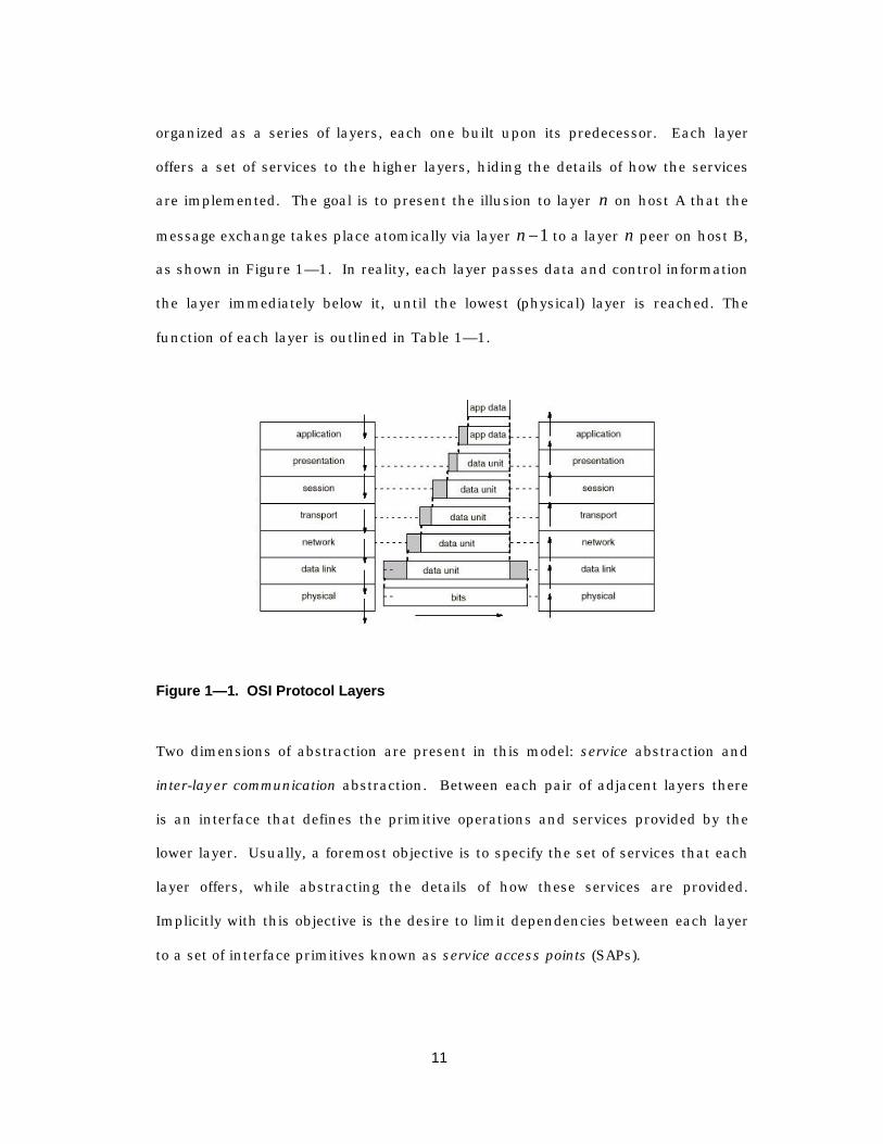
organized as a series of layers, each one built upon its predecessor. Each layer
offers a set of services to the higher layers, hiding the details of how the services
are implemented. The goal is to present the illusion to layer n on host A that the
message exchange takes place atomically via layer n - 1 to a layer n peer on host B,
as shown in Figure 1— 1. In reality, each layer passes data and control information
the layer immediately below it, until the lowest (physical) layer is reached. The
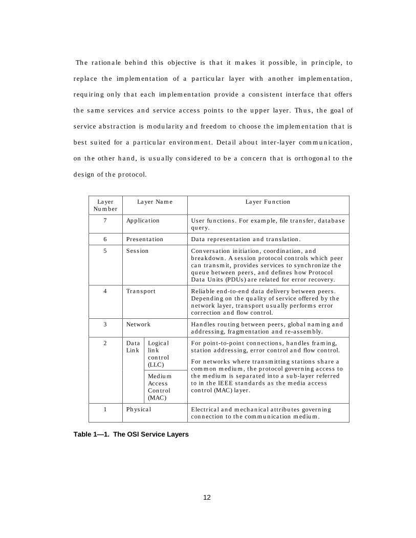
function of each layer is outlined in Table 1— 1.
Figure 1— 1. OSI Protocol Layers
Two dimensions of abstraction are present in this model: service abstraction and
inter-layer communication abstraction. Between each pair of adjacent layers there
is an interface that defines the primitive operations and services provided by the
lower layer. Usually, a foremost objective is to specify the set of services that each
layer offers, while abstracting the details of how these services are provided.
Implicitly with this objective is the desire to limit dependencies between each layer
to a set of interface primitives known as service access points (SAPs).
12
The rationale behind this objective is that it makes it possible, in principle, to
replace the implementation of a particular layer with another implementation,
requiring only that each implementation provide a consistent interface that offers
the same services and service access points to the upper layer. Thus, the goal of
service abstraction is modularity and freedom to choose the implementation that is
best suited for a particular environment. Detail about inter-layer communication,
on the other hand, is usually considered to be a concern that is orthogonal to the
design of the protocol.
LayerNumber
Layer Name Layer Function
7 Application User functions. For example, file transfer, databasequery.
6 Presentation Data representation and translation.
5 Session Conversation initiation, coordination, andbreakdown. A session protocol controls which peercan transmit, provides services to synchronize thequeue between peers, and defines how ProtocolData Units (PDUs) are related for error recovery.
4 Transport Reliable end-to-end data delivery between peers.Depending on the quality of service offered by thenetwork layer, transport usually performs errorcorrection and flow control.
3 Network Handles routing between peers, global naming andaddressing, fragmentation and re-assembly.
Logicallinkcontrol(LLC)
2 DataLink
MediumAccessControl(MAC)
For point-to-point connections, handles framing,station addressing, error control and flow control.
For networks where transmitting stations share acommon medium, the protocol governing access tothe medium is separated into a sub-layer referredto in the IEEE standards as the media accesscontrol (MAC) layer.
1 Physical Electrical and mechanical attributes governingconnection to the communication medium.
Table 1— 1. The OSI Service Layers

13
While this model provides an excellent starting point for conceptually partitioning a
set of protocol services, it must be used with care. This model has two implicit
assumptions that fail to hold in many practical contexts. First, there is the
assumption that cost of abstraction and separation is negligible compared to
advantage of being able to interchange layers. Second, there is an assumption that
interchanging layers that provide the same logical services – for example, a wired
physical layer and a wireless physical layer – provide equivalent service.
Since in wired networks the point-to-point network topology is essentially static,
physical-layer channels can be modeled as time-invariant systems and user-to-user
interference can be modeled as a stationary random process. Both of these
properties provide simple, understandable statistical models for characterizing the
probability of errors, justifying abstractions that allow the services provided to be
partitioned into orthogonal concerns. For example, a networked file system
provides the abstraction that all files reside on a single logical file system, greatly
simplifying the design of an application that read and write files using a standard
file I/O interface. In turn, the networked file system is simplified if it can assume a
black box, reliable packet delivery service from the lower-level network services.
The difficulty in applying this layering approach lies not in defining clean service
access points and abstracting lower level functionality; the real difficulty is in
separating the semantics of the service primitives. This is a subtle point, and one
worth further discussion.
The specification for the widely used ARPA Transmission Control Protocol (TCP), for
example, contains no explicit reference to a physical media or to any particular
style of implementation. Instead, it is assumed that the implementation has a
means of providing a best-effort datagram transfer service between endpoints, and
14
the TCP specification focuses solely upon higher level issues such as setting up a
connection, maintaining order, and so on. Informally, the SAPs to the lower levels
are primitives to send and receive datagrams. TCP maintains its own timer for
datagrams that still require an acknowledgement, and since corrupted packets
received by lower layers are discarded, TCP has no way of distinguishing between a
packet corrupted by bit errors from packets that are lost due to congestion in the
network.
TCP has been successfully used with a variety of lower-level media access protocols
such as carrier-sense multiple access (CSMA) and token ring, and on a variety of
physical media, including wireless, optical fiber, and wired media. Although the
TCP specification makes no explicit reference to the characteristics of the lower
layers, implicitly in the timeout and retransmission mechanisms there are the
assumption that the error rate is low, and that lost packets occur due to network
congestion. Accordingly, lost packets trigger a congestion-avoidance mechanism in
TCP that reduces the rate at which packets are sent. Thus when TCP is used over a
wireless link, a slight change in the packet error rate can mean that the
performance drops drastically due to the compounded effect of lost packets and a
rate reduction by the sender. An aggregate throughput of 25% of the link capacity
is typical of TCP over wireless [BPSK97].
The problem here arises due to misinterpreting the semantics of the event “lost
packet.” The appropriate behavior for the protocol depends strongly on the
semantics of this event, and misinterpretation leads to behavior that, although it
does not violate any safety or liveness properties, severely limits the usefulness of
the protocol.
15
1.4 An approach to integrating protocol design disciplines
This above example attests to the need to tailor protocols to the environment they
operate in, and is the strongest argument for a design methodology that integrates
performance metrics with functional correctness. Separating the design of the
protocol from the context in which it exists leads to performance penalties that are
unacceptable for wireless, portable applications. The remainder of this dissertation
explores the relationships between specification, verification, performance
estimation, and implementation. The summary of this exploration is presented here
as a guide for the reader.
The formal methods community has long advocated a methodology that begins with
an abstract, formal description of the system functionality that is supposed to be
the basis for rigorous formal verification and architectural exploration.
Conceptually, this provides the designer with an implementation-independent way
of evaluating a protocol or an algorithm. Further, this methodology proposes that
the designer refine this abstract description by successively adding implementation
details, proving at each step that the refinement is consistent with the original
specification.
In practice few if any formal methods are employed in the design community.
Informal text documents usually specify the system requirements, and the typical
design flow starts with simulation models based on these informal descriptions.
Simulation is then used to drive the bulk of the algorithmic exploration, and the
results of these simulations are used to elaborate and fine-tune the original design.
Typically, it is only after a prototype of the system has been built and checked via
16
black-box conformance testing [Hol92] that the system is checked against the
standard.
FormalVerification(Promela)
FormalSpec
(MessageSequence
Charts)
HardwareDesign(SMV/
Verilog)
SoftwareDesign
(C/C++/ASM)
Perf.Estimation
(DEsimulation)
FunctionalReqt’s
FormalModel(SDL)
MAC
LLC
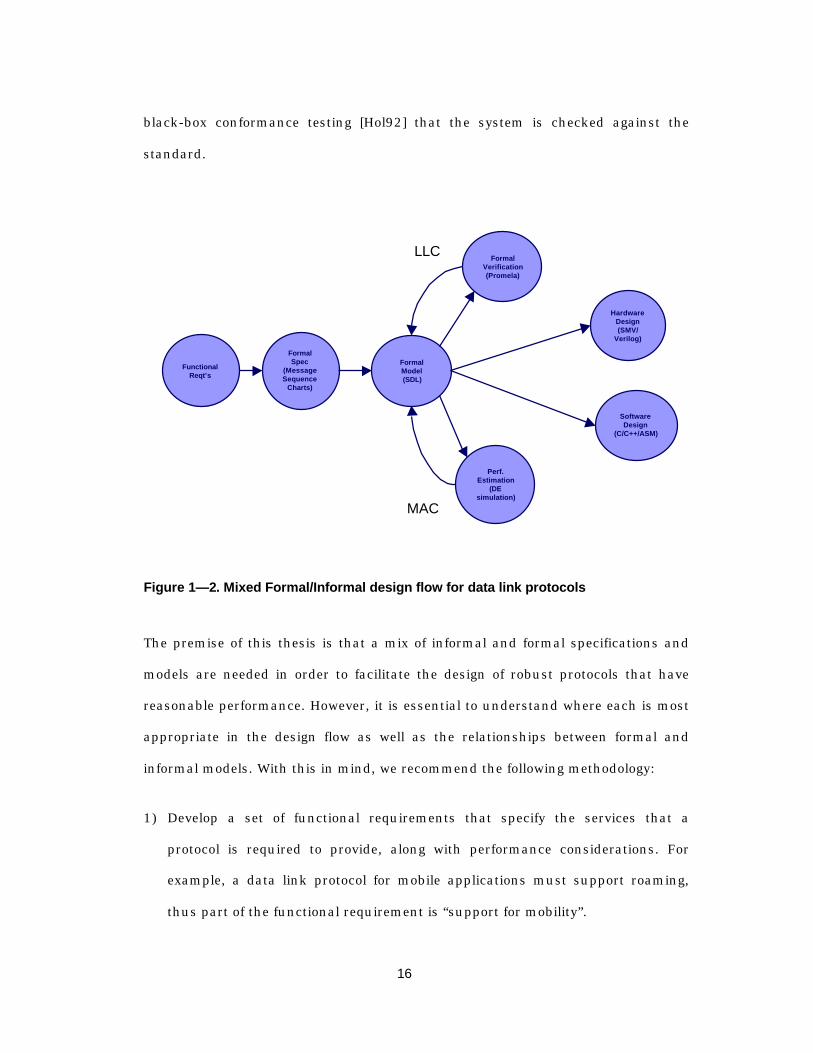
Figure 1— 2. Mixed Formal/Informal design flow for data link protocols
The premise of this thesis is that a mix of informal and formal specifications and
models are needed in order to facilitate the design of robust protocols that have
reasonable performance. However, it is essential to understand where each is most
appropriate in the design flow as well as the relationships between formal and
informal models. With this in mind, we recommend the following methodology:
1) Develop a set of functional requirements that specify the services that a
protocol is required to provide, along with performance considerations. For
example, a data link protocol for mobile applications must support roaming,
thus part of the functional requirement is “support for mobility”.
17
2) Develop an informal, coarse-grained architectural definition of the system that
identifies a set of message passing entities (e.g., mobile devices and
basestations), along with a (perhaps incomplete) set of message exchange
sequences for each protocol function. Performance considerations, along with
details about computation, data structures, etc., are omitted. The primary
purpose of this phase is to focus on the exchange sequences that comprise the
protocol, without regard to implementation, in typical scenarios. Message
sequence charts (MSCs) are one semi-formal approach that is provides a means
to graphically depict the actors, the state of each actor as time progresses, and
their possible interactions. In addition, this specification can be used later
during verification to check the trace-equivalence of the implementation at the
message passing and state transition level.
3) Develop a more detailed, formal state machine model of each actor in the
system, omitting performance-tuning features of the protocol during the early
stages. Though a variety of formal languages exist, the most widely accepted of
these is SDL, and is a reasonable choice for modeling functionality that is likely
to be implemented in software (e.g., the logical link and high-level MAC
functionality). The strength of SDL at this level is that it allows the designer to
focus on the state machines, the messages that are exchanged, and the
structure of the system at the block-diagram level. The formal semantics of
timers, channels, and message passing allows the designer to focus creative
effort on the design of the protocol rather than on developing a simulation
infrastructure and defining the state machine using the semantics of a
simulator.
18
4) At this point the design process branches into two largely independent tasks:
formal verification and performance estimation. Logical link protocols are by
nature distributed-state concurrent systems and the design process must
insure the logical consistency of the protocol, and are thus the primary target
for formal verification in our context1. This is because formal verification
focuses on proving properties about the system given a set of possible events,
without regard to the probability of any event. So, for example, one would like
to prove that the logical link could not deadlock under packet reordering or loss
events. On the other hand, the media access control protocol consists of an
algorithm that is designed to minimize the interference between users, and its
evaluation must be done in terms of the probabilities of collision, loss, and
corruption. Thus, performance estimation will largely focus on the media access
algorithm.
5) Finally, the system is ready to be implemented as a mix of hardware and
software. For hardware subsystems, it is not desirable to directly map an SDL
process onto a hardware implementation: the result is semantically incon-
sistent with the abstractions that SDL enforces (detailed in Chapter 3 and
Chapter 5). Chapter 5 presents a compositional refinement methodology
whereby it is possible to informally relate a high-level, asynchronous FSM,
message-passing view of the system to a detailed hardware implementation. In
Chapter 6, we consider a path from a high-level language such as SDL to
software, and present an operating system implementation that provides the
1 For wireless systems, logical link protocols include both link establishment protocols andlink management protocols that support mobile users.

19
infrastructural "glue" that is necessary to combine the hardware and software
implementations.
1.5 Summary of Contributions
This work addresses the design methodology for link-level protocols that are
implemented in embedded systems. The primary contributions are as follows:
1) A taxonomy of formal languages that have been applied to protocol design
2) The relationship between specification, formal verification, performance
estimation, and implementation as applied to the protocol design and
implementation
3) A semi-formal methodology for mapping SDL to synchronous hardware
implementations using compositional refinement to verify that an
implementation conforms to a high-level specification
4) A decomposition of a generalized data transfer network that allows end-to-end
verification of data integrity, transfer completion, and data ordering
5) A roadmap for further research on the problem of integrating formal description
techniques into to design and implementation flow
In this thesis, we do not address the technologies underlying the "performance
estimation" phase of protocol design. Of the four protocol design technologies,
performance estimation is the one that is most often used in working designs, and
for this reason we focus our energies on aspects of the design that are less familiar
to the design community.
20
1.6 Outline of the dissertation
The dissertation is organized as follows. Chapter 2 uses a large-scale system design
example to explore the process of starting with a set of informal constraints and
mapping these constraints onto a protocol design. Chapter 3 investigates the
languages that are used to specify protocols using formal (i.e., mathematical)
languages, and presents a taxonomy of execution and communication models for
the most well-known formal languages. Given a formal model of a protocol, it
becomes possible to address the problem of formally proving properties about the
model. Chapter 4 presents a tutorial on the most common formal verification
technologies as they apply to hardware and protocol verification, and introduces
some recent work in compositional refinement verification that provides the
theoretical underpinnings for the following chapter.
In Chapter 5, we consider the methodological challenge of mapping protocols from
a high-level, asynchronous concurrent execution, abstract “message-passing”
domain (e.g., SDL) to an implementation-level domain with synchronous
concurrent execution. This forms the basis of a “semi-formal” approach to protocol
design and implementation that combines SDL modeling with an informal mapping
to a high-level model using a synchronous language known as SMV. This high-level
SMV model can then be incrementally refined into an implementation, and at each
step of the refinement process it is possible to check that a refinement is consistent
with the original high-level specification.
Chapter 6 turns to the more general problem of relating an SDL system to an
implementation in a mix of hardware and software. The problem is one of mapping
high-level message-passing semantics of SDL onto a combination of synchronous
21
hardware and non-deterministically interleaved software threads, as well as
providing the infrastructural resources such as queues, timers, and schedulers in
an embedded operating system.
Finally, Chapter 7 provides an in-depth look at the design of the data link
initialization and link management protocols for the InfoPad system and outlines
the challenges of formally verifying the link level protocols. Chapter 8 concludes the
dissertation with an eye to extensions of this work.
22
Chapter 2
I n f o rma l Spec i f i ca t i on o fP r o t o co l Sys t em
R e q u i r e m e n t s
2.1 Overview
The first step in any protocol design is to determine the service requirements. That
is, what set of services is the protocol intended to provide to external programs
(which include higher layers in the protocol stack). Simultaneously one must define
required services that the protocol layer of interest will not provide: this defines the
dependencies on services from the lower level protocols.
The scope of our methodology ranges from specification through implementation.
To motivate and define the context for the data link and media access protocols, we
start by examining a full system design of a wireless communication system known
as InfoPad [TPD97][NSH96]. Our goal is to give the reader a feeling for the range of
problems that the methodology must address.

23
The InfoPad system is an example of a large system design in which ad-hoc design
methodologies were used. The data link protocols were informally documented
using graphical representations of state transition systems. With a few sketches of
protocol state machines, an implementation in hardware and software was the next
objective, before any high-level performance estimates or formal verification results
were obtained. Finally, the implementation was incrementally debugged over a
period of several months as the implementation began to stabilize. In hindsight, the
strength of an abstract state machine language with clean message-passing
semantics and language constructs that are designed to facilitate protocol
specification would have greatly simplified the eventual task of implementing the
protocol simply because it would be easier to understand what must be
implemented.
In Section 2.2, the top-level system is described qualitatively together with the
overarching design objectives; from this we derive a set of informal constraints for
the link level protocols. In Section 2.3, we outline a functional partitioning of the
system that identifies the message-passing interactions between functional units.
For our system, the message-passing entities generally fall into one of 3 categories:
1) network management or mobility support; 2) multimedia server or client; or 3)
the mobile device. We consider each of these in Sections 2.3.1.1, 2.3.1.2, and 2.3.2,
respectively.
Once the initial system architecture is in place, we turn our attention to the
qualitative performance objectives. These objectives define a set of constraints can
be broadly classified as either functional or performance-oriented. (A subset of
these constraints is discussed in Section 2.4.)

24
For example, a qualitative performance objective is that the wireless network
connection should be maintained transparently to a roving user: cell-to-cell
handoffs should, if at all possible, avoid dropping the link. We can split this
requirement into the following constraints:
1) Performance constraint: The protocol should minimize the probability of
dropping the link
2) Functional constraint: protocol must provide both for handoff without drop-out
and for recovery in the case where the link is dropped
The point here is that an informal constraint often translates into a series of formal
constraints1, some of which are performance-oriented and some of which are
function-oriented. It is important to understand the difference because the tools
used to analyze and determine whether the implementation meets the constraint
are radically different for the two types of constraints. Performance-oriented
constraints are usually handled using a combination of hand analysis and discrete-
event simulation; functional constraints must be formally verified.
This abstract view of the system must undergo a series of refinements before an
implementation is possible. Since the latter part of our methodology focuses on the
implementation phase, it is useful to follow a portion of the system through to
implementation, laying the groundwork for the refinement methodology presented
in Chapter 5.
1 In this example, we use the word formal in the sense that it is possible to prove whether theconstraint is satisfied

25
Since the InfoPad was designed to be a tool for research in mobile communication
systems, there are many features in the hardware implementation that support
dynamic configuration for protocol support and would be of interest to a protocol
systems designer. Section 2.5 presents an in-depth look at the design of the mobile
device, and will be referenced in Chapter 5; however, it is intended primarily as a
reference section and may be safely skipped in a first reading.
2.2 An informal high-level description of the InfoPadsystem
There is presently a re-examination of the requirements of the system architecture
and hardware needed for personal computing for the new and ever-growing class of
users whose primary computing needs are to access network information and
computing resources, as well as real-time interactive activities (chat rooms, games)
and direct communications with other people. These applications, which are more
communications-oriented than computation-oriented, require a “personal
computer” that primarily has support for high bandwidth real-time
communications as well as multimedia I/O capabilities – including audio,
text/graphics and video. User-accessible general-purpose programmability and
local high-performance computation are a secondary requirement, desirable only if
the increased complexity and cost to support stand-alone operation, which is
required for disconnected or poorly connected operation, can be justified.
As the dependence on network information storage and computation increases, the
desire to ubiquitously access the network will require the terminal to have the
portability of a paper notebook (1 lb., 8/12x11x1/4”) while still being able to
support real-time multimedia capabilities. These goals require a sophisticated
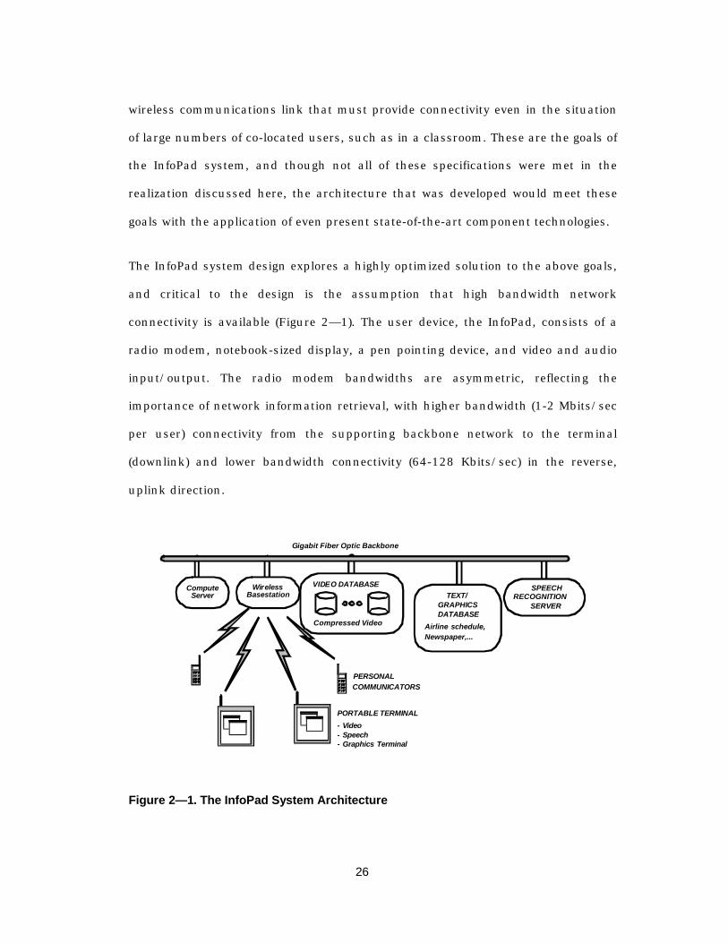
26
wireless communications link that must provide connectivity even in the situation
of large numbers of co-located users, such as in a classroom. These are the goals of
the InfoPad system, and though not all of these specifications were met in the
realization discussed here, the architecture that was developed would meet these
goals with the application of even present state-of-the-art component technologies.
The InfoPad system design explores a highly optimized solution to the above goals,
and critical to the design is the assumption that high bandwidth network
connectivity is available (Figure 2— 1). The user device, the InfoPad, consists of a
radio modem, notebook-sized display, a pen pointing device, and video and audio
input/output. The radio modem bandwidths are asymmetric, reflecting the
importance of network information retrieval, with higher bandwidth (1-2 Mbits/sec
per user) connectivity from the supporting backbone network to the terminal
(downlink) and lower bandwidth connectivity (64-128 Kbits/sec) in the reverse,
uplink direction.
VIDEO DATABASE
Compressed Video
Gigabit Fiber Optic Backbone
Wireless
GRAPHICS
SPEECHRECOGNITION
DATABASE
TEXT/
- Video
PORTABLE TERMINAL
PERSONALCOMMUNICATORS
Airline schedule,Newspaper,...
SERVER
ComputeServer Basestation
- Speech- Graphics Terminal
Figure 2— 1. The InfoPad System Architecture
27
Since portability and widespread consumer use was an important requirement, it
was necessary to reduce the energy consumption, weight and cost of the design as
much as possible. For this reason, exploitation of the availability of the network
connectivity and access to network servers was deeply built into the overall system
architecture [NSH96]. The InfoPad essentially functions as a remote I/O interface,
in which computing and storage resources are removed from the portable device
and are placed on a shared, high-speed backbone network of servers, which
provide mass storage, general-purpose computation, and execution of system and
user-level applications [SCB92][BBB94][CBB94].
The InfoPad system architecture allows dramatic simplifications in both the actual
hardware that is used as well as the software and system management. A brief
summary of some of the most important advantages is outlined below:
Reduced cost, complexity and energy consumption – Moving the general purpose
computing resources out of the portable device maximally reduces the cost, weight and
energy consumption, by eliminating mass storage, high performance processors, and
memories. Energy consumption for specific communication or I/O functions can be
reduced by several orders of magnitude by replacing general-purpose computation with
dedicated architectures.
Ease of use and remote system support – Support for sophisticated applications and
operating systems is provided by remote network managers. In this respect the use
model is closer to that provided by the telecommunications industry, in which the user
I/O device, the telephone, has little complexity and the network providers perform
system support and maintenance.
28
Appearance of unlimited storage and computational resources – since applications and
server processes run on servers on the backbone network, it is possible to run
sophisticated applications and computationally-intensive I/O algorithms – speech and
handwriting recognition, for example – without the cost or energy consumption incurred
in providing local high performance computation. Similarly, mass data storage is
provided by storage and application servers rather than in local disks or flash memory.
We mentioned in earlier that the overall system constraints often have a dramatic impact
on the service requirement for the link level protocol and on the implementation of the
protocol. Considering the system described above, we can infer that the most critical
constraints are as follows:
1) High-bandwidth, low-latency service that supports interactive multimedia
2) An energy-efficient implementation
3) Support for mobility, with dynamic network reconfiguration
4) Data-dependent quality of service, given the over-subscribed wireless link
Since the link-level protocol handles only the point-to-point link, these constraints are
viewed in terms of their impact on the design of the mobile device and the "basestation"
that provides the logical and physical connection between the wireless link and the
backbone network. However, since part of the link protocol includes support for mobility,
we must also consider network-wide support for roaming.
2.3 A “message-passing” architectural pa rtitioning
At this point, we have a first-order description of the design objectives for the entire
system. The second step in the methodology outlined in Chapter 1 requires
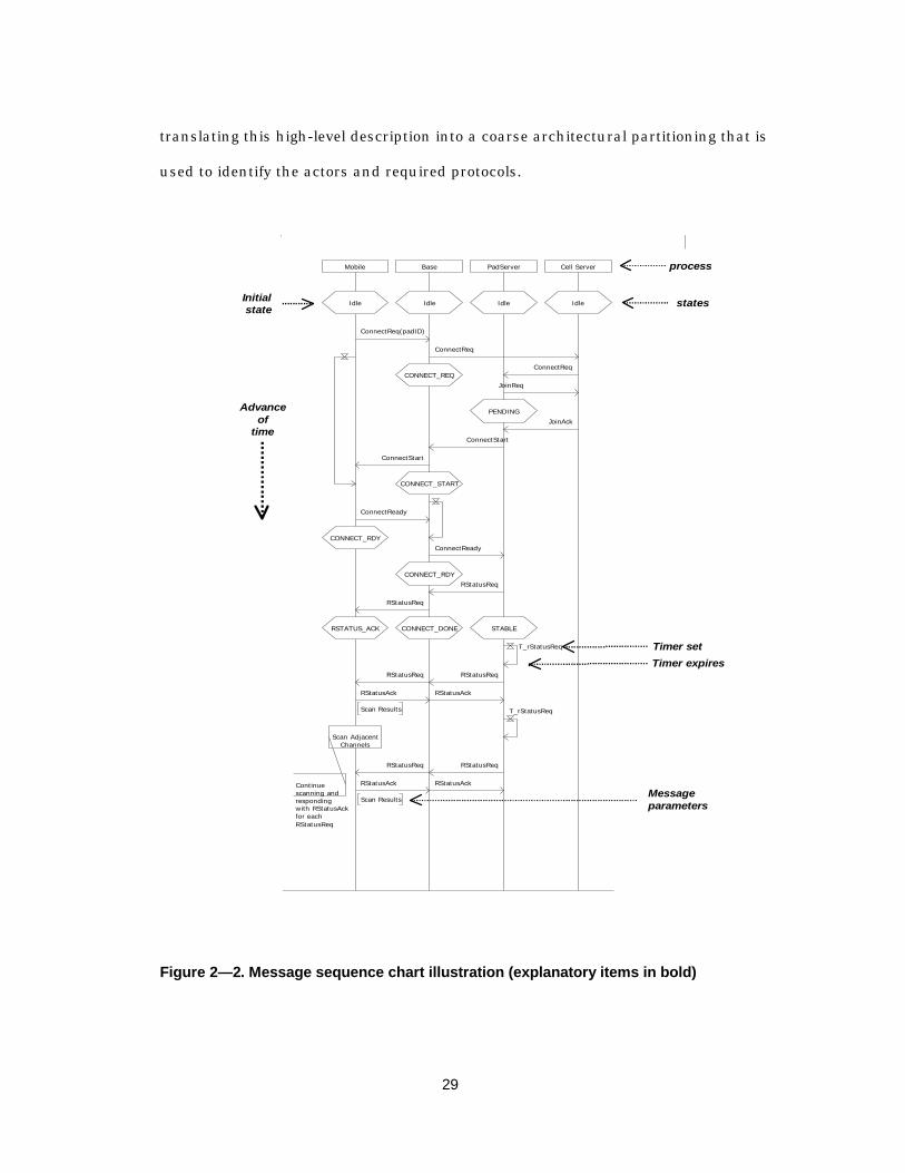
29
translating this high-level description into a coarse architectural partitioning that is
used to identify the actors and required protocols.
Mobile Base PadServer Cell Server
IdleIdleIdleIdle
ConnectReq(padID)
ConnectReq
CONNECT_REQConnectReq
JoinReq
PENDINGJoinAck
ConnectStart
ConnectStart
CONNECT_START
ConnectReady
CONNECT_RDYConnectReady
CONNECT_RDYRStatusReq
RStatusReq
CONNECT_DONERSTATUS_ACK STABLE
T_rStatusReq
RStatusReq RStatusReq
RStatusAckRStatusAck
Scan Results T_rStatusReq
Scan AdjacentChannels
RStatusReqRStatusReq
RStatusAck
Scan Results
RStatusAckContinuescanning andrespondingwith RStatusAckfor each RStatusReq
process
states
Timer set
Timer expires
Messageparameters
Advanceof
time
Initial state
Figure 2— 2. Message sequence chart illustration (explanatory items in bold)
30
Figure 2— 2 depicts a Message Sequence Chart [ITU93c][RGG95] partition of the
system architecture that includes the backbone network support for resource
allocation and mobility (the CellServer and PadServer) along with the basestation
and the mobile device. Each of these entities can be further refined to include a
more detailed view of the particular subsystem of interest – in fact, this is precisely
what the latter steps in the methodology will address.
The development of a set of message sequences capturing the various scenarios
that the protocol is expected to encounter is perhaps the most useful, yet most
frequently overlooked, step in the protocol design flow because it clearly identifies
the interaction and state relationships between concurrent processes. Further, the
high degree of abstraction provides a clear view of the essential interactions.
The difficulty with this step is that a message sequence represents an execution of
some part of the system, and for complex designs the number of cases one must
consider quickly grows beyond what is tractable for complete specification using
message sequences. Thus, typically a few critical sequences are specified, while
others are at the discretion of the designer, relegated to the next phase, in which a
finite-state transition system is used to model the protocol system.
In any case, a thorough understanding of the functional requirements is necessary
before detailed message sequences can be defined. To provide the reader with the
functional requirements placed on a reasonably complex protocol, in the following
sections we address the major features of the mobility support protocols, the
multimedia I/O servers, and the mobile device. We begin with an overview of the
backbone network support for mobility.
31
2.3.1 The InfoNet network infrastructure
As described in [NSH96], the InfoNet system provides the backbone network
support for the InfoPad. An overarching system requirement for the InfoNet was
that it must support both legacy applications and mobile/InfoPad-aware
applications.
To this end, InfoNet provides a proxy agent – the Pad Server – that acts logically as
a single, fixed (non-mobile) InfoPad. All network connections to other servers (e.g.,
video server or graphics server) are routed directly to the Pad Server and logically
terminate there.
2.3.1.1 Mobility support
The network is physically divided into picocells, typically about the size of a single
room. Each cell has a basestation/gateway that provides the physical and logical
interface between the wireless and wired network. This gateway interacts closely
with a Cell Server that is responsible for resource management within each cell.
Upon startup, the mobile device listens for periodic beacons that are broadcast by
the basestation. These beacons identify the basestation, the cell to which the
basestation is logically attached, and other information that will be used to
synchronize the mobile with the basestation.
When the mobile has located one or more candidate cells, it requests to join a cell
by sending a JoinRequest to the basestation. This request is forwarded to the cell
server for the current cell, and the cell server in turn contacts the "pad server"
proxy agent and negotiates the join process.
32
After a mobile has successfully joined a cell, the pad server periodically requests
status updates from the mobile. These status reports include the signal strength
measurements taken from adjacent cells, which are used to drive the decision to
handover a mobile to an adjacent cell.
2.3.1.2 Multimedia I/O support
The multimedia services provided by the network to the InfoPad are contained
within 4 primary I/O servers:
1) The speech server, which accepts audio from the uplink and performs speech
recognition
2) The pen server, which accepts stylus coordinates from the uplink and provides
logical “pointer” functions
3) The graphics server, a modified X11 server that provides a logical windowing
system interface to applications, and manages the screen-refresh policies for
the InfoPad
4) The video server, which compresses a real-time video stream and forwards the
compressed video and compression codebooks to the InfoPad
As mentioned above, each of these I/O servers are logically connected to the Pad
Server.
The following section presents the architecture of the InfoPad portable multimedia
terminal itself, which can be thought of as a simple I/O interface that is logically
connected directly to each of the above servers via a wireless link.
33
2.3.2 Architecture of the InfoPad terminal
Externally, the InfoPad terminal provides a pen- and speech-based user interface to
applications, along with a graphics and full-motion video display. Since the link to
the network is central to the operation of the device, a natural model for the
portable device is that it is simply a multimedia-enabled extension of the backbone
network. Several architectural features distinguish the InfoPad from desktop,
notebook, and network computers as well as from PDAs and PIMs. These features
are outlined below.
Peripheral vs. central processing unitExperience with an earlier prototype [BBB94] indicated that the microprocessor
subsystem, which was responsible for managing data transfers between the
wireless modem and the I/O-processing chipset, consumed a significant fraction of
the overall power budget and was also a primary performance bottleneck. The most
delay-sensitive activities, such as moving the pen and expecting the cursor to track
location in real-time, typically generate a large number of very small data transfers,
so that the microprocessor spends the majority of its cycles entering and exiting
interrupt service routines and setting up data transfers. Due to the delay-
sensitivity and asynchronous nature of these transfers, it is difficult to amortize the
transfer setup overhead over more than one or two I/O packets.
The requirements outlined above lead to an optimization in which the user
accessible central processing unit (CPU) is functionally removed from the
architecture of the portable and networked based resources are used instead.
Unlike a local CPU architecture, in which I/O peripherals enhance the functionality
of the core processor, our goal was to design intelligent peripherals that process
I/O events and manage data transfers without relying on a centralized processor.

34
Instead, the general-purpose processing unit is viewed as simply another peripheral
subsystem which exists to complement the functionality of the I/O peripherals,
thus the processor is more appropriately termed a peripheral processing unit (PPU).
Class-based communications protocolsThroughout the Pad architecture, it was necessary to distinguish between classes
of data, where each class has its own service needs, primarily because of the
required support of interactive multimedia over a wireless network, where
bandwidth is limited and reliability can vary dramatically. The heterogeneous mix
of traffic supported over the wireless link requires that the link level protocol be
aware of the delay and reliability requirements of a particular packet, and tailor the
behavior of the protocol to meet the requirements of each class of traffic.
For example, in a vector-quantized image compression scheme, it is possible to
differentiate the quantization codebook from the quantized image. Since the
codebook is relatively small and will be used to decode many image frames,
increasing the reliability of the codebook transmission (via forward error correction
coding, retransmission, or a combination of both) has little impact on the overall
bandwidth requirements but has a dramatic impact on the overall quality of the
decompressed image. Data frames, which require more bandwidth and are more
delay-sensitive, can be transmitted with little or no error correction: corrupted
image frames with bit-error rates of up to still provide the viewer with a good idea
of the overall image composition [HM96].
Low-overhead, minimal-state communicationsConsistent with the goal of exploiting network resources, the amount of state
maintained in the portable device is minimized and for this reason explicit support
35
for end-to-end transport and internetworking protocols over the wireless link is
avoided. Instead, focus was is on the link between the mobile and basestation, in
which optimized link-level protocols are tailored to variable rate multimedia traffic
and the low reliability of wireless transmission.
Since applications execute on the backbone network, and general-purpose network
connections between applications exist entirely within the backbone infrastructure,
the mobile is relieved from the task of handling “standard” protocols. Often these
protocols are designed for generality, and either require superfluous fields in the
protocol data structures or exhibit behavior that is unsuitable for use on error-
prone wireless links. Additionally, by assuming a connection-oriented protocol
between the basestation and the other servers on the backbone network, it is
possible to view the wireless link as a simple extension of this connection, where
the basestation acts as a proxy network termination for the transport- and
network-layer protocols. Since the connection to the backbone network is a single-
hop link, routing between the basestation and the Pad is not required, obviating the
need for an internet protocol and the associated overhead.
At the transport layer, an end-to-end, connection-oriented protocol such as TCP is
not well-suited to the transmission of real-time, isochronous data across a wireless
link. Re-transmitting a lost image frame from a streaming movie, or attempting to
retransmit a lost audio frame would in many cases violate the delay constraints for
these data types. Further, no well-known transport protocol is particularly suited to
the burst error characteristics of the wireless channel. (With TCP in particular, the
congestion-avoidance mechanism enhance negative effects of retransmission, since
a burst of errors interpreted as severe congestion in the channel, forcing the sender
to further restrict the rate of transmission [BPSK96]).

36
An infrastructure for mobile multimedia computing researchIn order to support the architectural features described above, it is necessary to
design and build an infrastructure of network resources. This includes the design
of interactive applications, multi-modal user interfaces, source and channel coding
algorithms, network protocols, and base station architectures that are specifically
targeted to wireless multimedia.
2.4 Service Requirements: Performance aspects vs.functional aspects
The above system-architecture objectives provide a starting point for defining the
service requirements for the data link and media access protocols. In such a
design, we are starting with an almost unlimited solution space. Thus, we need a
means by which we can compare different approaches.
As mentioned above, we can identify both a performance aspect and a “functional
correctness” aspect. Performance issues are primarily optimization problems, and
so of necessity they focus on common-case behavior and are typically addressed
using probabilistic analysis or discrete-event simulation. Functional issues, on the
other hand, are often dealing with corner cases that are difficult to exercise using
simulation tools and are typically addressed using formal verification.
In this section, we provide a few selected examples from this InfoPad system that
illustrate how one moves from a high-level informal specification to specific service
requirements, and show how the service requirements can be broken into
performance estimation issues and verification issues.
First, we identify the primary services that our protocols are to provide:
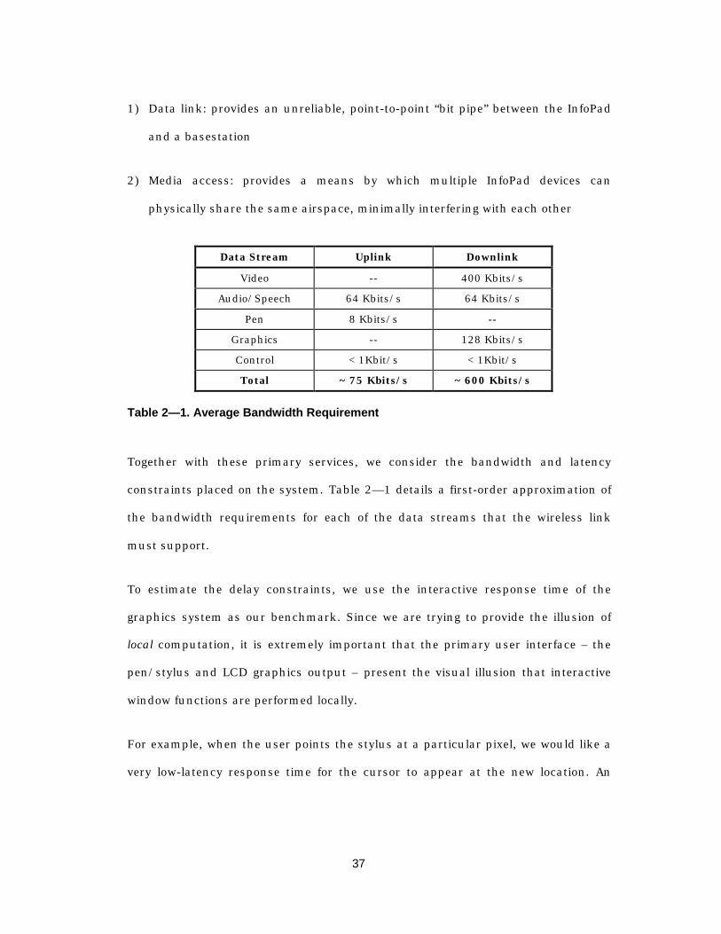
37
1) Data link: provides an unreliable, point-to-point “bit pipe” between the InfoPad
and a basestation
2) Media access: provides a means by which multiple InfoPad devices can
physically share the same airspace, minimally interfering with each other
Data Stream Uplink Downlink
Video -- 400 Kbits/s
Audio/Speech 64 Kbits/s 64 Kbits/s
Pen 8 Kbits/s --
Graphics -- 128 Kbits/s
Control < 1Kbit/s < 1Kbit/s
Total ~ 75 Kbits/s ~ 600 Kbits/s
Table 2— 1. Average Bandwidth Requirement
Together with these primary services, we consider the bandwidth and latency
constraints placed on the system. Table 2— 1 details a first-order approximation of
the bandwidth requirements for each of the data streams that the wireless link
must support.
To estimate the delay constraints, we use the interactive response time of the
graphics system as our benchmark. Since we are trying to provide the illusion of
local computation, it is extremely important that the primary user interface – the
pen/stylus and LCD graphics output – present the visual illusion that interactive
window functions are performed locally.
For example, when the user points the stylus at a particular pixel, we would like a
very low-latency response time for the cursor to appear at the new location. An
38
aggressive upper bound of 30 milliseconds1 was placed on the round-trip time that
it takes for a stylus coordinate to be generated, sent via the uplink, basestation,
and gateway to the pen server, which then forwards the coordinate to the X11
server. The X server renders the background fill for the old location, renders the
cursor in the new location, and forwards both of these bitmap blocks to the
gateway/basestation before it is transmitted via the downlink.
For this system, the round-trip latency bound together with the bandwidth
requirements form the primary basis for evaluating the suitability of various media
access and handoff strategies.
Table 2— 2 summarizes selected functional requirements that the data link protocol
must provide, and illustrates how these functional requirements can be mapped to
performance constraints and functional constraints. In this partitioning of protocol
support, the data link protocol is required to provide the point-to-point link
between the mobile and the base. Thus, the protocol must provide a mechanism for
establishing, creating, monitoring, and using this point-to-point link.
For example, initially a mobile must scan for candidate cells and basestations to
which it will present a request to join. Thus, the protocol must provide for
“announcements” from a basestation and “join requests” from a mobile. There
must also be a protocol for assigning a mobile to exactly one cell, and a protocol for
distributing this information to the rest of the system. If the request to join a cell is
rejected, the protocol must specify what options the mobile can exercise in seeking
1 This 30 millisecond figure is based on the screen refresh rate: generating the new cursorposition any sooner would give no perceptible improvement to the interactive feel of the userinterface.
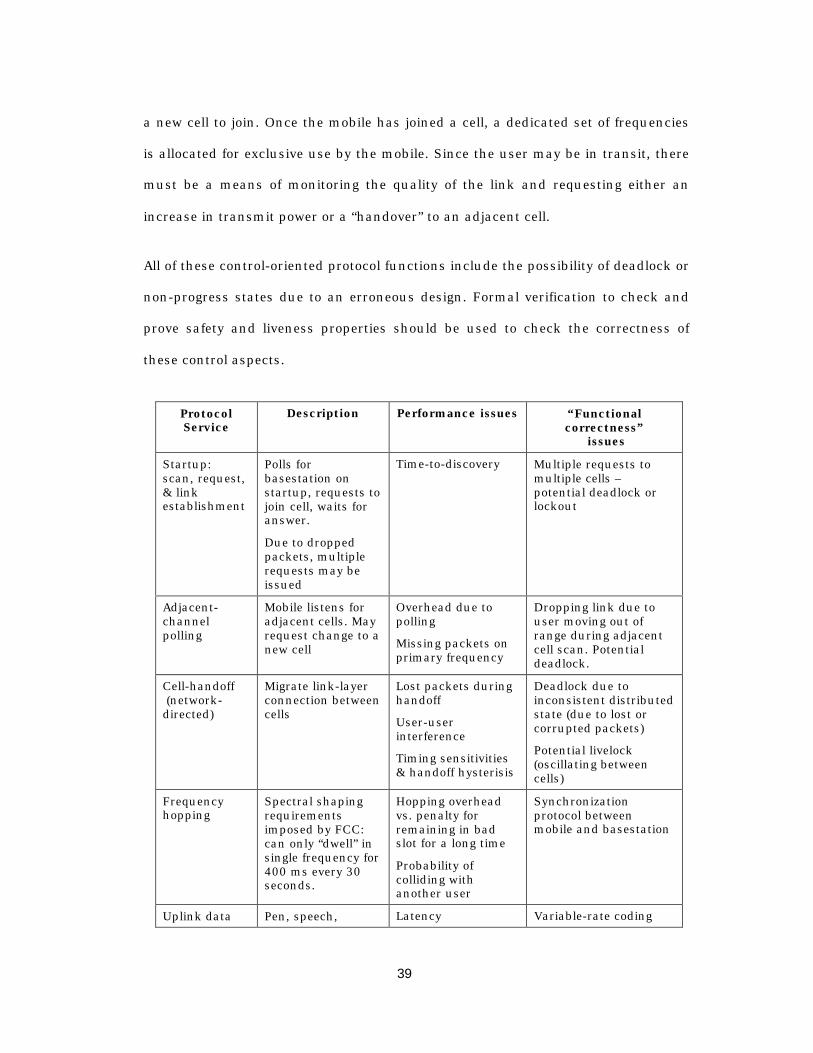
39
a new cell to join. Once the mobile has joined a cell, a dedicated set of frequencies
is allocated for exclusive use by the mobile. Since the user may be in transit, there
must be a means of monitoring the quality of the link and requesting either an
increase in transmit power or a “handover” to an adjacent cell.
All of these control-oriented protocol functions include the possibility of deadlock or
non-progress states due to an erroneous design. Formal verification to check and
prove safety and liveness properties should be used to check the correctness of
these control aspects.
ProtocolService
Description Performance issues “Functionalcorrectness”
issues
Startup:scan, request,& linkestablishment
Polls forbasestation onstartup, requests tojoin cell, waits foranswer.
Due to droppedpackets, multiplerequests may beissued
Time-to-discovery Multiple requests tomultiple cells –potential deadlock orlockout
Adjacent-channelpolling
Mobile listens foradjacent cells. Mayrequest change to anew cell
Overhead due topolling
Missing packets onprimary frequency
Dropping link due touser moving out ofrange during adjacentcell scan. Potentialdeadlock.
Cell-handoff (network-directed)
Migrate link-layerconnection betweencells
Lost packets duringhandoff
User-userinterference
Timing sensitivities& handoff hysterisis
Deadlock due toinconsistent distributedstate (due to lost orcorrupted packets)
Potential livelock(oscillating betweencells)
Frequencyhopping
Spectral shapingrequirementsimposed by FCC:can only “dwell” insingle frequency for400 ms every 30seconds.
Hopping overheadvs. penalty forremaining in badslot for a long time
Probability ofcolliding withanother user
Synchronizationprotocol betweenmobile and basestation
Uplink data Pen, speech, Latency Variable-rate coding
40
delivery control protocol Buffer overflow
Downlink datadelivery
Video data &codebooks,graphics, audio,and controlprotocols
Latency
Buffer overflow
Variable-rate decoding
Table 2— 2. Selected protocol services and their performance and functionalconstraints
On the other hand, the “performance” aspects of the protocol have softer
correctness metrics that capture the probabilistic, common case behavior. We
would like to characterize the average delay and queue length of the transmit path,
for example. We would also like to know how well we are utilizing the available
bandwidth, and how much we are wasting due to protocol overhead.
These performance issues are best characterized using discrete event simulation.
However, a common mistake is to attempt to model the performance of the system
at the implementation level, rather than first developing high-level, abstract models
of various pieces of the system and using these high-level simulations to drive
architectural choices. As we move through the descriptions of the InfoPad in the
following sections, we will point out implementation decisions that were strongly
influenced by performance goals, and will discuss a variety of abstractions that
could be used to model aspects of the system.
2.5 Following the methodology through to implementation:the design of the InfoPad terminal
The purpose of integrating a high-level protocol description language into the
design flow is that it enables a much simpler initial specification because the
language itself provides semantic constructs that are useful for describing protocol

41
systems. The problem, however, is that the abstractions that enable high-level
system design are inappropriate for use in the low-level implementation, especially
when the implementation is in the synchronous hardware domain. We will address
this problem in great depth in Chapters 3 and 5. At this point we simply note that a
bridge is needed to relate a protocol specification to its implementation.
Chapter 5 considers in great detail one approach to relating the specification to the
implementation, using a technique known as compositional refinement verification.
In that chapter, we consider the implementation of the multimedia I/O subsystems
on the InfoPad hardware terminal, and the interaction of these subsystems with the
wireless link control system.
The remainder of this section presents in detail the design and implementation of
the hardware components of the InfoPad multimedia terminal. It is included for
completeness and to explain in detail how the data processing subsystems interact
with the wireless link protocols. It can safely be skipped during a first reading.
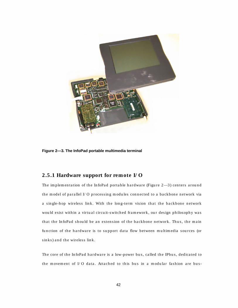
42
Figure 2— 3. The InfoPad portable multimedia terminal
2.5.1 Hardware support for remote I/O
The implementation of the InfoPad portable hardware (Figure 2— 3) centers around
the model of parallel I/O processing modules connected to a backbone network via
a single-hop wireless link. With the long-term vision that the backbone network
would exist within a virtual circuit-switched framework, our design philosophy was
that the InfoPad should be an extension of the backbone network. Thus, the main
function of the hardware is to support data flow between multimedia sources (or
sinks) and the wireless link.
The core of the InfoPad hardware is a low-power bus, called the IPbus, dedicated to
the movement of I/O data. Attached to this bus in a modular fashion are bus-
43
mastering data sources and bus-slave sinks, as depicted in Figure 2— 5. Together,
these I/O devices support two-way audio, pen input, monochrome graphics, and
color video capabilities over a full-duplex wireless link; they are implemented as 10
full-custom ASICs in a 1.2-micron CMOS process. A microprocessor system is used
to handle system initialization and higher-level protocol functions (e.g., collecting
error statistics and signal strength measurements).
Conceptually, the architecture is analogous to an output-buffered, self-routing
packet switch. At run-time, each data source is given a type-tag1 which is used to
identify the type of data generated (e.g., pen vs. speech), and for each {data source,
type tag} pair a unique device destination address is assigned. When a source has
data of a particular type available, it uses the type tag to dynamically determine the
corresponding sink to which the data should be sent. Thus, once initialization is
complete, data transfers between source and sink are autonomous, requiring no
microprocessor intervention.
The type tag provides a mechanism to support lightweight protocols that provide
data-specific transport services. For example, the transmitter interface module uses
the tag to determine how the current packet is to be encapsulated, since optional
fields such as packet length, forward error correction, or sequence number, may be
omitted for certain types.
1The assignment of tags to a particular data class is globally shared with the backbone network software.
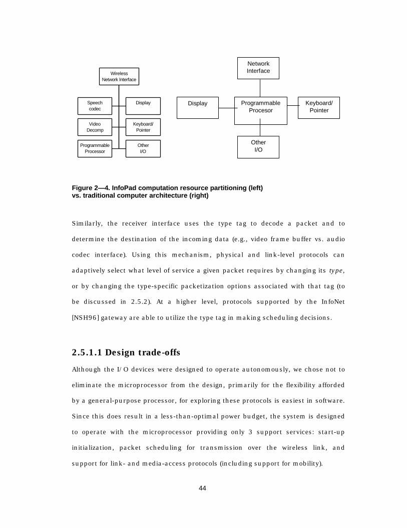
44
Speechcodec
Display
VideoDecomp
Keyboard/Pointer
ProgrammableProcessor
OtherI/O
WirelessNetwork Interface
ProgrammableProcesor
Display Keyboard/Pointer
NetworkInterface
OtherI/O
Figure 2— 4. InfoPad computation resource partitioning (left)vs. traditional computer architecture (right)
Similarly, the receiver interface uses the type tag to decode a packet and to
determine the destination of the incoming data (e.g., video frame buffer vs. audio
codec interface). Using this mechanism, physical and link-level protocols can
adaptively select what level of service a given packet requires by changing its type,
or by changing the type-specific packetization options associated with that tag (to
be discussed in 2.5.2). At a higher level, protocols supported by the InfoNet
[NSH96] gateway are able to utilize the type tag in making scheduling decisions.
2.5.1.1 Design trade-offs
Although the I/O devices were designed to operate autonomously, we chose not to
eliminate the microprocessor from the design, primarily for the flexibility afforded
by a general-purpose processor, for exploring these protocols is easiest in software.
Since this does result in a less-than-optimal power budget, the system is designed
to operate with the microprocessor providing only 3 support services: start-up
initialization, packet scheduling for transmission over the wireless link, and
support for link- and media-access protocols (including support for mobility).
45
A second power-related concession was made in the design of the wireless
interface: the physical interface to the RF modems utilizes an commercially-
available FPGA to enable experimentation with both the wireless modem and the
physical-layer protocols (e.g., FEC coding, clock recovery, etc.). Radio technology is
rapidly advancing; and while current radio technology is adequate for experimental
designs (the current downlink radios operate at 640 Kbit/s), they do not provide
the 2-10 Mbit/s envisioned for future devices. The FPGA design provides an
interface which is easily changed to take advantage of new radios as they become
available.
Overall, the primary technical challenge was to balance the low-power design
against system flexibility (for use as a research tool), and system responsiveness
(for actual use). In the following sections, as we discuss the specifics of the I/O
subsystems, we will identify the design trade-offs and implementation choices that
are driven by the architectural goals presented in Section II.
2.5.1.2 IPbus Description
The IPbus is an 8- bus designed to run at a speed of 1MHz and a supply voltage of
1.2-1.5 Volts. This design provides a maximum throughput of 8Mbit/s, well above
the 1 Mbit/s maximum supported by the radios, ensuring that the IPbus
bandwidth is adequate for system dataflow. An 8-bit word size was chosen to
minimize pin count, and hence package size, of the custom ASICs; a larger word
size would not measurably improved system performance since the system
throughput is constrained by the bandwidth of the radio channel.

46
Speech
Video
Pen
Text/Graphics
Protocolcontroller
Receive Interface
IPbus
Audio
ProtocolController
Transmit Interface
TransmitterPhysicalInterface
ReceiverPhysicalInterface
Mux
Demux
FIFOs
Module
Module
Figure 2— 5. IPBus and architectural organization of dataflow
The IPbus supports direct read/write transfers as well as a packet-based transfer
mechanism. Utilized only by the microprocessor subsystem, the direct read/write
mechanism allows the processor to directly configure a device, query status, and
respond to interrupt conditions. Packet-based transfers are used for inter-device
communication: the source device indicates a new transfer by sending a start of
packet (SOP) byte, followed by a variable number of data bytes, and terminates the
transfer by sending an end of packet (EOP) byte to the sink device. Included in the
SOP byte is the 6-bit type tag which identifies the data-type of the packet (e.g. pen,
audio, etc.). The EOP byte contains additional (optional) status information, which
can be used to identify packets that are corrupted during transmission over the
wireless link, for example.
Data transfers are not required to be atomic: distinct data streams from different
sources can be interleaved across the bus, and simultaneous transfers to the same
sink device by multiple sources are allowed. For example, it is possible for the
47
audio, the pen, and the microprocessor to simultaneously transfer data to the
transmitter interface. This removes the requirement for store-and-forward protocols
in the I/O peripherals, decreasing the overall system delay, but requires that the
sink devices be capable of demultiplexing the incoming data.
2.5.2 Wireless Interface Subsystem
In the early design phases (1992-1993), the dearth of high-speed wireless modems
suitable for use in the InfoPad and the uncertainty that standard link-level
protocols would provide adequate performance for multimedia over wireless,
demanded reconfigurable wireless interface - one that was flexible in its ability to
interface to a variety of wireless modems, as well as the ability to support
experimentation with link and media access protocols. Our strategy was to
partition the interface into three parts, shown in Figure 2— 6: a transmitter (TX)
interface ASIC; a receiver (RX) interface ASIC; and a reconfigurable physical
interface module, implemented in an FPGA. The TX and RX modules handle
packet- and byte-oriented functions, while the FPGA provides bit-level
manipulations, such as forward error correction (FEC) coding, and the physical
signalling interface to the wireless modems. This partitioning allows the underlying
modem to change, requiring neither a change to byte- and packet-oriented
operations nor an ASIC refabrication.

48
TransmitInterface
FPGA
PhysicalInterface
ReceiveInterface
Bytes Out
Tx Byte Clk
Rx Byte Clk
Bytes In
Tx Bits Out
Tx Bit Clk
Rx Data In
To ProximRDA 100
From PlesseyDE6003(625 Kbit/s)
(242 Kbit/s)
IPbus
Figure 2— 6. Block diagram of wireless interface subsystem
In the following subsections, we outline the salient features of the protocol support
primitives.
Packet structureThe basic packet structure supported over the wireless link is an extension of the
IPbus packet format, shown in Figure 2— 7. The minimum overhead added by the
wireless link is the single-byte pad alias, which is an address equivalent.
Optionally, sequence number, packet length, and CRC fields may also be added.
The inclusion of sequence numbers is a Pad-specific configuration parameter. The
other optional fields are type-specific, giving a very fine granularity on how the link
protocols treat particular classes of data, supporting our goal of providing
lightweight, type-specific communications protocols.
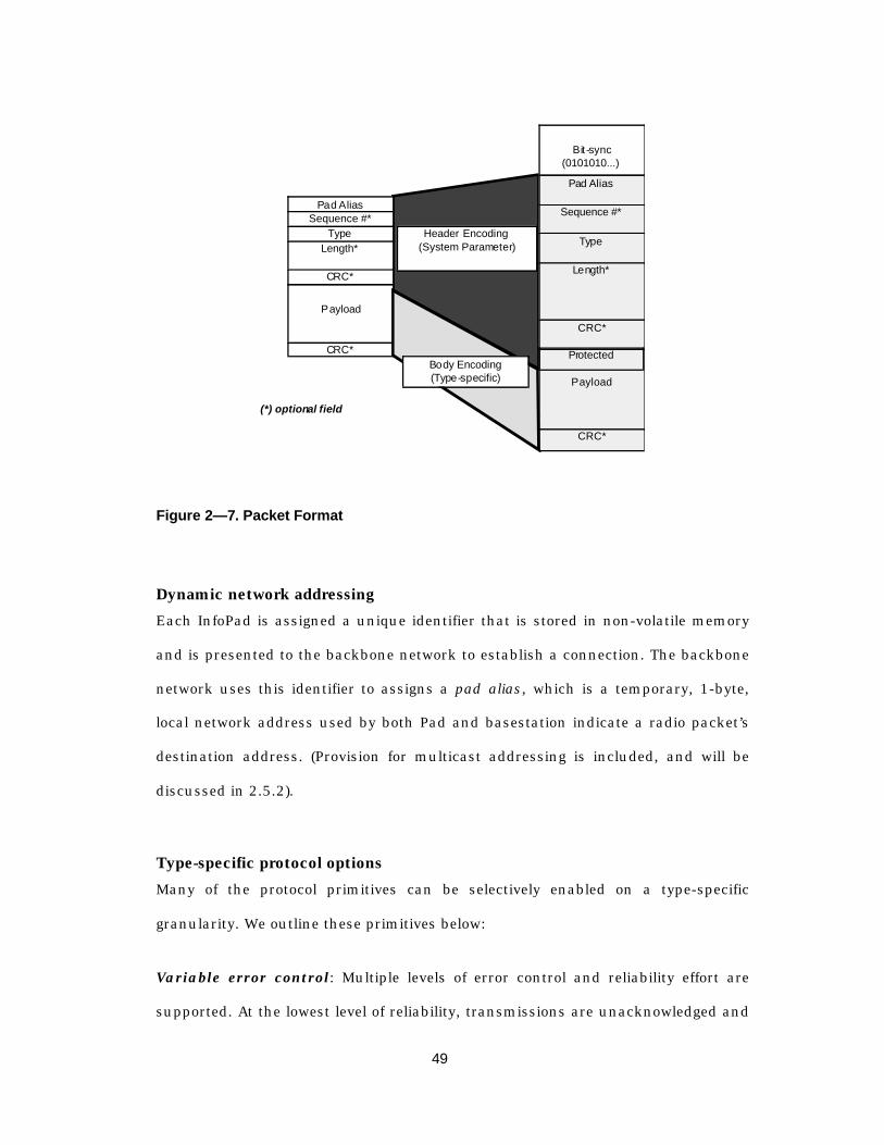
49
Header Encoding(System Parameter)
Pad Alias
Payload
CRC*
Sequence #*Type
Length*
CRC*
Pad Alias
Protected
Payload
CRC*
Sequence #*
Type
Length*
CRC*
Bit-sync(0101010...)
(*) optional field
Body Encoding(Type-specific)
Figure 2— 7. Packet Format
Dynamic network addressingEach InfoPad is assigned a unique identifier that is stored in non-volatile memory
and is presented to the backbone network to establish a connection. The backbone
network uses this identifier to assigns a pad alias, which is a temporary, 1-byte,
local network address used by both Pad and basestation indicate a radio packet’s
destination address. (Provision for multicast addressing is included, and will be
discussed in 2.5.2).
Type-specific protocol optionsMany of the protocol primitives can be selectively enabled on a type-specific
granularity. We outline these primitives below:
Variable error control: Multiple levels of error control and reliability effort are
supported. At the lowest level of reliability, transmissions are unacknowledged and

50
no error correction or error detection is employed; at the highest-level of reliability,
a Type-1 Hybrid ARQ protocol is used. Additionally, two different error correction
codes1 are available: a BCH (15,5,3) code, and a BCH (15,11,1) code. These
variable-level encoding schemes allow bandwidth-intensive data (such as graphics
or video) to be minimally encoded, while latency or content-critical data (such as
video codebooks or pen packets) can be maximally encoded.
Differentiation of packet header and packet payload: An insight gained from
experience with the earlier prototype is that for many classes of data packets, there
often are a few content-critical bytes which require higher reliability than the rest of
the payload - a bitmap, for example, has an x- and y-coordinate followed by a series
of pixel values, and displaying the bitmap at the correct location is far more critical
than displaying every pixel value correctly.
For this reason, we chose to provide a mechanism that allows the link protocols to
differentiate between packet header and packet payload: at a type-specific
granularity, it is possible to encode the first 1-7 bytes of the payload with the same
FEC coding as the packet header, while the remainder of the payload is encoded
independently. An optional payload CRC field is available for data types that
require correct transmission. In this way, it is possible to have the content-critical
bytes maximally encoded, while the remainder of the payload is encoded at a
completely different level. Interleaving is a standard mechanism for increasing the
effectiveness of error correcting codes in the presence of burst errors [LC83].
1 An (n,k,t) error correcting block code uses transmitted bits to send information bits, andcan correct up to errors in bits.
51
Interleaving: The TX and RX subsystems provide a 15x16 interleaver/de-
interleaver, which redistributes 240-bit blocks of FEC-encoded data into 16 15-byte
blocks. In this configuration, we are able to correct a large number of burst errors
of up to 48 bits in each 240-bit block.
In the remainder of this section, we outline the particular features of the wireless
interface components.
TX Interface
The TX subsystem is responsible for demultiplexing interleaved data streams (sent
from different sources) and buffering them until they can be encapsulated and
metered out to the FPGA interface. Data is encapsulated with the InfoPad radio
packet format which provides additional functionality such as error detection,
length information, etc. Packet scheduling is accomplished in cooperation with the
microprocessor subsystem.
The TX chip provides five distinct logical channels, each of which can handle one
non-interleaved data stream. A single source per logical channel mapping is
enforced in software. Associated with each logical channel is a ring buffer which
provides storage for packets pending transmission (Figure 2— 8). Each ring buffer
has a programmable number of entries - pointers to packets in an external memory
- with up to 32 entries per ring. The number of buffers for each channel, as well as
the size of each buffer, can be dynamically adjusted according to the type of traffic
carried by the channel.
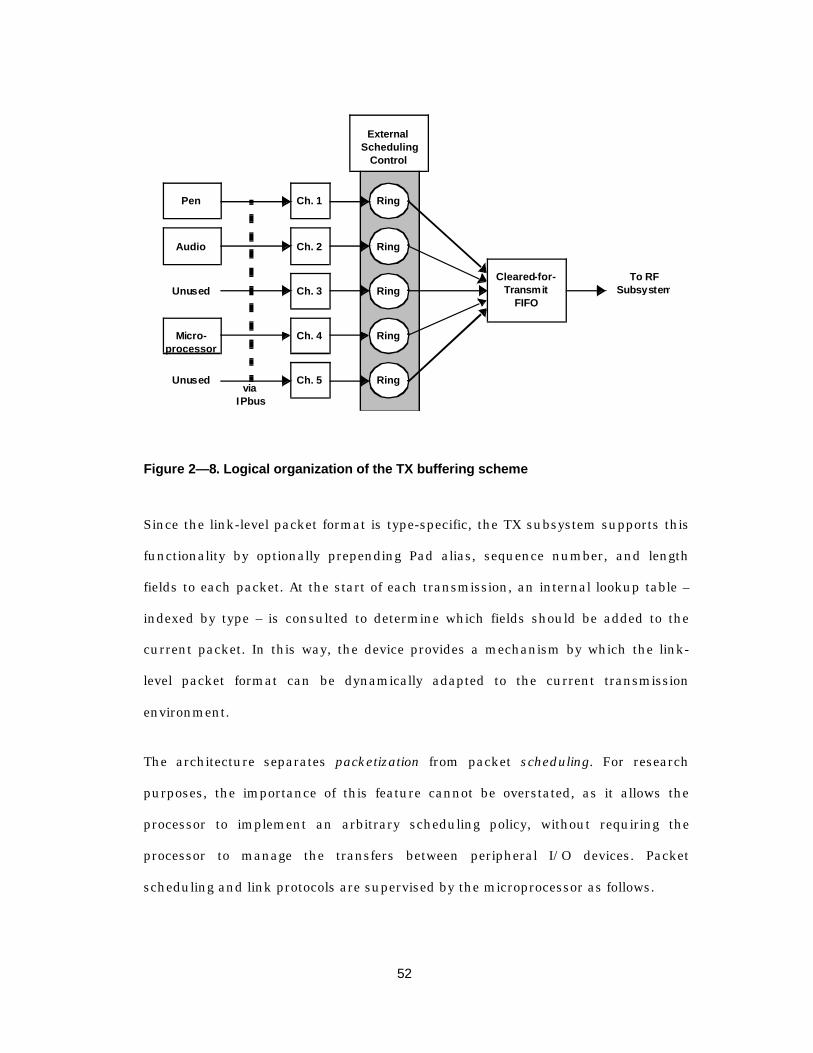
52
Ch. 1 Ring
Ch. 2 Ring
Ch. 3 Ring
Ch. 4 Ring
Ch. 5 Ring
To RF Subsystem
Pen
Audio
Unused
Micro-processor
Unusedvia
IPbus
ExternalScheduling
Control
Cleared-for-Transmit
FIFO
Figure 2— 8. Logical organization of the TX buffering scheme
Since the link-level packet format is type-specific, the TX subsystem supports this
functionality by optionally prepending Pad alias, sequence number, and length
fields to each packet. At the start of each transmission, an internal lookup table –
indexed by type – is consulted to determine which fields should be added to the
current packet. In this way, the device provides a mechanism by which the link-
level packet format can be dynamically adapted to the current transmission
environment.
The architecture separates packetization from packet scheduling. For research
purposes, the importance of this feature cannot be overstated, as it allows the
processor to implement an arbitrary scheduling policy, without requiring the
processor to manage the transfers between peripheral I/O devices. Packet
scheduling and link protocols are supervised by the microprocessor as follows.
53
Upon the receipt of a complete packet, the TX chip issues an interrupt to the
processor subsystem. The processor reads the {ring number, buffer number, packet
type, length} information from the device and records this information. At some
time in the future, the processor may choose to queue this packet for transmission
by pushing the {ring number, buffer number} to a “ready for transmit” FIFO in the
TX module. At the completion of packet transmission, the TX chip again issues an
interrupt, indicating that the packet represented by {ring number, buffer number}
has completed transmission.
RX Interface
The RX subsystem is responsible for processing the incoming radio traffic. It
processes the packet headers received from the FPGA and routes the data body to
the appropriate destination. Packet headers can optionally be duplicated and
forwarded to the local microprocessor for statistical monitoring, allowing the
microprocessor to monitor the packet traffic, dropped packets, and passed/failed
CRCs without processing or transporting body data.
The internal architecture of the device is a simple state machine that controls data
flow to an internal FIFO. Packet destination is determined by a programmable
lookup table based on the packet’s type field, which enables a number of data flow
scenarios. In normal operation, data is sent directly to the appropriate sink device,
though for debugging, specific data types can be routed through the
microprocessor, allowing monitoring, modifying, and rescheduling the packet before
forwarding to its final destination.
The device performs only simple, pass-through routing: once data is available in
the receive FIFO, it is transferred out to the IPbus at the first opportunity. One

54
disadvantage of this pipelined reception path is the inability of the receiver
subsystem to drop incoming packets, since the payload CRC is not available until
after the packet data has been forwarded on to the data sink. Therefore, data sinks
that wish to discriminate between clean and corrupted data must buffer incoming
bytes before processing can proceed.
In addition to supporting point-to-point addressing via the pad alias, the RX
interface supports both multicast and broadcast addressing. A second alias, the
group alias, is used to identify a particular multicast group; incoming packets with
an Alias field matching either the pad alias register or the group alias register are
accepted by the receiver module. With the exception of broadcast packets, all other
packets are ignored.
FPGA Interface
The FPGA subsystem is the intermediary between the RX or TX subsystems and
the physical radios. In addition to providing the error correction coding and CRC
modules, the primary responsibilities are outlined below:
Signaling interface: since there is no standard physical interface to wireless
modems, supporting multiple physical interfaces is a task which is particularly
well-suited to programmable logic. Virtually all wireless modems support a
common set of control signals such as power up/down, channel selection,
transmit/receive selection. The FPGA module provides an abstraction of the
underlying mechanisms, so that the RX, TX, and processor modules have a
uniform view of the wireless modem primitives.
55
Timing and data recovery: On the downlink, the DE6003 modem interface
presents only the raw received data signal - i.e., the analog output of a hard-
limiting comparator (binary FSK modulation is used). This signal, which is has a
nominal bit rate of 625 Kbits/sec, is oversampled by a factor of 16 (10 MHz), and is
used to recover both the timing information and data sequence. At the start of a
transmission, a sequence of 48 alternating 1’s and 0’s is sent, followed by a 32-bit
framing character; once this is received, the tracking feedback loop is opened for
the duration of the packet. Due to an implementation limitation of these modems,
the maximum continuous transmission is 10 milliseconds, so that clock drift
between transmitter and receiver during a packet time is small enough to ignore1.
Real-time interrupt: To support real-time protocol requirements (e.g., frequency
hopping), a real-time interrupt is provided with up to a 5 microsecond resolution.
For reservation-based media access, the guard interval between channel uses is
inversely proportional to the accuracy of the reservation timer. Placing the timer
block near the receive path provides a convenient mechanism for accurately (within
a bit-time) synchronizing the mobile with the basestation.
2.5.3 Microprocessor Subsystem
The microprocessor is responsible for system initialization and various high-level
protocols. The system is based around an ARM60 microprocessor running at 10
MHz with 512 KB of RAM, with 128 KB ROM for program storage.
1 The 20 MHz system clocks are accurate to plus/minus 20 PPM
56
To maintain power efficiency, the microprocessor system is designed with hardware
support for a software-initiated idle state. When the software determines that it has
no more work to be done, i.e., when waiting for some external stimulus, it signals
an external controller to initiate the idle state. This controller gates the system
clock, freezing the processor in mid-cycle and driving its power consumption to a
minimum. The processor interrupt line is monitored by the controller, and with the
next interrupt (e.g., a timer event or incoming data), the controller reactivates the
processor clock.
2.5.4 Microprocessor Interface Chip
The processor interface (ARMIF) device is the bridge between the microprocessor
bus and the IPBus, and its main roles are buffering data, byte-to-word conversion,
and performing miscellaneous control functions. In the active mode, the Master
channel directs data from the processor to the peripheral I/O chips (video,
text/graphics, audio, transmitter), while the Slave channel collects packets from
the chipset (pen, speech, and radio transmitter). A third channel, the Direct
read/write channel, provides an unbuffered read and write mechanism so that the
processor is able to program the control registers and read back the status
registers of the peripheral chips.
2.5.5 User Interface I/O Peripherals
2.5.5.1 Graphics Subsystem
The graphics subsystem is the primary output device for the InfoPad system. It
consists of a low-power SRAM frame buffer (described fully in [CBB94]), a controller
module, and 640x480 monochrome LCD. Graphics operations (e.g., line drawing

57
and text display) are performed in the backbone network in the graphics server
[NSH96], and the resulting bitmaps are sent directly over the wireless link and are
rendered by the controller module.
Three shapes of bitmaps are supported: rectangular block, horizontal line, and
vertical swath (32 bits wide, variable height.) Normally, received bitmaps are
displayed regardless of the correctness of their content; if bit errors are incurred
during wireless transmission then the data is displayed with errors. This design
choice was driven by the desire to maintain a responsive interactive user interface
with bit error rates above .
A second mode, called protected mode, queues incoming bitmap data and displays
it only if it the packet payload passes CRC. This is used in conjunction with a
technique known as asymptotically reliable transmission [HM96],[Han97]. To
maintain the responsiveness of the user interface, an initial, possibly corrupted,
version of a bitmap is rendered as quickly as possible; in the background, the
graphics server follows the initial transmission with low-priority1, protected-mode
update packets that cyclically refresh the entire screen. In this scheme, corrupted
packets that were previously displayed are eventually replaced by either a clean
refresh image or an entirely new image (again possibly corrupted). This approach
provides a very responsive interactive feel while providing a means by which,
asymptotically, the screen image can be rendered without errors.
1 These packets can be transmitted at lowest priority, utilizing unused transmissionbandwidth.

58
2.5.5.2 Pen Subsystem
The pen interface utilizes a commercially-available digitizer tablet, which is
attached to the underside of the graphics LCD panel. This digitizer feeds pen
coordinates and button status to a custom ASIC, which provides a buffered
interface to the IPbus. With the first available byte of pen data, the ASIC initiates
an IPBus transfer to the Target Address, followed by a programmable number of
data bytes; this configuration allows the system software to fine-tune the buffer size
in order to balance round trip delay against the overhead incurred by sending very
short packets. (In the current implementation, the default pen packet size is 5
bytes).
2.5.5.3 Audio Subsystem
The audio subsystem performs bi-directional audio buffering and provides a
physical interface to a commercial codec, amplifier, and speaker. The audio
channel supports 8 KHz 8-bit -law encoded audio, which presents the wireless link
with 64 Kbit/s raw audio bandwidth. Downlink audio is buffered in a 1 Kbyte FIFO,
smoothing the delay jitter in the incoming audio packets. Uplink audio is generated
at the same 8 KHz rate and transferred to its destination (typically the TX interface)
via the IPBus.
2.5.5.4 Video Interface
The video subsystem supports full-motion color video. A custom ASIC
implementation consisting of 5 decompression chips plus 4 custom, low-power
frame buffer ASICs, drives the external add-on color display [CBB94]. Ideally, the
video display and graphics display would be combined, reducing system
59
complexity; however, during the design phase, lightweight, thin, low-power, color
LCDs were unavailable.
As detailed in [CBB94], video data is transmitted using an adaptive vector
quantization compression scheme which divides the compressed information into
two distinct types -- video data and video codebooks – each of which has differing
transport demands. The compression scheme used can deliver up to 30
frames/second over the wireless link.
2.5.6 Evaluation and Measurements
The implementation described in the proceeding section uses a combination of full-
custom ASICs and commercially available components to provide the required
functionality and demonstrate the viability of the architecture. In several places,
providing this functionality with commercial components came at a significant
increase in the power budget. However, the lack of available components (or
weaknesses in the underlying technology) has fueled further research efforts to
close the gap: energy efficient microprocessor design [BB97]; low-power, energy-
efficient DC-DC conversion [SSB94]; fully-integrated, CDMA transmitter and
receiver implemented in CMOS [SLP96]; and circuit design for energy-efficient
reconfigurable logic devices are several of the complementary research projects
which were spawned from the InfoPad project.
In this section, we evaluate the strengths and weaknesses of the design, making a
distinction between architecture limitations and implementation-specific
limitations. We begin with a power breakdown by subsystem.
60
2.5.6.1 Architectural Evaluation
As a preface to an architectural evaluation, we return to the fundamental
assumption about the role of the terminal in the overall system: that the portable
terminal is a remote interface to networked I/O servers, where the interface devices
generate data at a pre-determined maximum rate. Hence, data throughput or
computational performance is not a useful characterization of the system, since as
long as the device is able to process incoming and outgoing I/O packets at the pre-
determined rate (e.g., video frame rate, graphics frame rate, pen I/O packet rate,
etc.) there is no advantage to making the device “faster.” Our evaluation is thus
restricted to a consideration of how well the internal architecture supported the
design requirements.
Processor Utilization
As mentioned earlier, one of the goals was to minimize, and ideally eliminate, the
role of the microprocessor subsystem in the overall design, in order to reduce power
consumption. Fig. 8 illustrates that of the non-video power budget the
microprocessor subsystem accounts for 20% of the power consumption
(approximately 1.4 Watts) in fully-active operation (100% duty cycle). However,
since the microprocessor subsystem is composed of fully-static CMOS components,
gating the clock reduces the power consumption to approximately 0.25 Watts
(power due to clock distribution only). During normal operation of the InfoPad, the
measured duty cycle shows that the processor is active 7% of the time when
running at 10 MHz; this yields an average power consumption of 0.33 Watts.
While active, the processor spends the majority of its cycles servicing the TX
module, which has only a 1 MHz read/write interface. Waiting for I/O peripherals
61
while responding to packet-ready notifications, clearing packets for transmission,
and responding to transmission-complete notifications dominate the time that the
processor subsystem is not in sleep mode.
Remote-I/O Processing Latency
A critical metric of the usefulness of the remote I/O architecture is the round-trip
latency incurred as a packet moves through successive stages in the system. While
the dominant source of latency is the network interfaces on the backbone network,
early measurements ([NSH96] [BBB94] [LBS95]) using standard workstations
attached to a 10 Mbit/s Ethernet backbone demonstrate that a 30 millisecond
round-trip latency was an achievable design constraint for a LAN-based backbone.
This goal is based on the graphics refresh interval and gives the user an
imperceptible difference between local- and remote-I/O processing for the pen-
based user interface. Given this constraint, it is useful to evaluate the processing
latency introduced by the interface between the IPbus peripherals and the wireless
link. We break this latency into the following three components:
Packet generation: 3 microseconds. This is defined to be the time elapsed from
when the last byte of available uplink data until the packet is reported ready (i.e., a
request for scheduling is generated). The bus-mastering architecture of the IPbus
provides a direct path from each data source to the wireless network interface (via
the TX chip buffers) without involving the processor. Thus, the packet generation
latency is typically less than three IPbus clock cycles.
Scheduling : 160 microseconds. This is the time required to process the
scheduling request and clear the packet for transmission. To facilitate
experimentation with a variety of scheduling algorithms and media-access
62
protocols, packetization and scheduling are separated. Partitioning these functions
into physically separate units increases the complexity of the packetizer by
requiring it to support random access to available packets. This partitioning also
increases inter-module communication by requiring the packetizer to interact with
the scheduler several times for each packet, and each interaction requires several
bus transactions.
The current implementation, with an idle transmitter and an empty transmit
queue, has a worst case time on the order of 160 microseconds Ñ 50 microseconds
to notify the processor, 10 microseconds for the processor to clear the packet for
transmission, and 100 microseconds for the first bit of data (after 64 bits of
synchronization preamble) to be transmitted over the wireless link.
Packet distribution: 1 microsecond. This is defined as the time elapsed from the
moment the first byte of available downlink data is ready until the first byte of the
packet is sent to its destination device (e.g., pen, audio, etc.). Since the architecture
employs direct, unbuffered routing from source to destination, the packet
distribution latency is simply the time required to determine the hardware
destination address for the given type, which can be accomplished in a single IPbus
clock cycle.
The sum of these three components is 164 microseconds. This latency is
insignificant compared to the latency incurred in the backbone network (10-20
milliseconds).
63
Communications Protocol Support
Because the InfoPad architecture supports type-specific link protocols, it is possible
to experiment with a variety of protocols, and, given the current transmission
environment, to fine-tune the parameters of each protocol to best handle each type
of data. By characterizing the typical traffic patterns for each data type – a
characterization which may be performed either off-line or dynamically – it is
possible to eliminate unused fields, and to optimize for the common case.
The data link protocol, which provides a unreliable point-to-point link over the
wireless medium, relies on the 1-byte pad alias field to indicate the receive address,
and on the type-tag field (1 byte) to identify the data type of the current packet.
Optionally, this layer includes any combination of the following: packet length (2
bytes), sequence number (1 byte), header CRC (1 byte), and payload CRC (1 byte).
Relative to standard protocols for wireless transmissions, this 7-byte overhead is
significantly less: on a 5-byte pen packet, for example, typically only the pad alias
and two CRC fields are added, incurring a 37% overhead. For comparison, the
IEEE 802.11 draft standard, which uses a 28-byte MAC frame header, requires
660% overhead.
2.5.6.2 Implementation Evaluation
Power consumption
The totals for the power consumption, broken down by subsystem, are presented in
Table 1, and are graphically summarized in Fig. 8. The figures indicates the
maximum power consumption, which is measured when all subsystems are fully
active (100% duty cycle). Complete with the video display module, the InfoPad

64
consumes 9.6 Watts, an order of magnitude higher than the ideal power budget.
Processor6%
Misc Support1%
Misc I/O9%
Wireless30%
LCD10%
Custom I/O Peripherals
2%
DC/DC42%
Video Display40%
Wireless18%
Processor4% Custom I/O
Peripherals1%
LCD6%
Misc I/O5%
DC/DC25%
Misc Support1%
Figure 2— 9. Power breakdown by subsystem with video display (left) and withoutvideo display (right)
The external video display, however, was intended to demonstrate the feasibility of
compressed full-motion video over a wireless link and to demonstrate the low-
power decompression chipset. It is worthwhile to consider the system without the
external color video display because it is such a large fraction of the power
consumption (3.9 Watts), and since comparable color LCD panels that consume
less than 1 Watt are now commercially available. In the discussion below, we
analyze the non-video power budget.
Without the video display, the inefficiencies of DC/DC conversion surprisingly
dominates the total power dissipation. These standard, off-the-shelf converters
typically operate at 70-80% efficiency, expending nearly 2.5 Watts (42% of the total
power) in providing the required supply voltages. The need for efficient DC/DC
conversion is clear: a 90%-efficient voltage conversion, for example, reduces the 2.5
Watts currently dissipated to 0.9 Watts – a 25% reduction in the total InfoPad
power budget.
65
To address this need, a new DC/DC conversion design methodology has been
developed, and a proof-of-concept low-voltage prototype IC has been demonstrated
which remedies many of the limitations of current-day solutions [SSB94]. Smaller
size and lower power systems are achieved through the highest levels of CMOS
integration together with higher operating frequencies and minimum-sized inductor
selection. A synchronous rectifier, whose timing is controlled in a low-power DLL,
enables nearly ideal soft-switching and efficient conduction, even at ultra-low
output voltages. Typical converter efficiencies range from above 90% at full load
and 1.5 V and above, to 80% at minimum current load and voltages as low as 200
mV.
The second largest power consumer is the wireless link subsystem: including the
FPGA interface module (0.6 Watts), the uplink and downlink radios (0.55 and 0.53
Watts, respectively), and the A/D converter for measuring received signal strength
(0.25 Watts). This accounts for 30% of the total power dissipation, and the desire to
substantially reduce the power dissipation in this subsystem has fueled research
both in low-power reconfigurable logic [AR96], and in low-power RF transceiver
design [SLP96].
Form factor
Including the battery pack, the InfoPad measures 11 inches by 12 inches, is 1.3
inches thick, and weighs 3.3 pounds (1.1 kg). An open-case view of the InfoPad is
shown in Figure 2— 10. Figure 2— 11 graphically summarizes the contribution, by
subsystem, to the weight and surface area of the device.

66
Figure 2— 10. Interior view of the InfoPad terminal
Higher levels of integration are the most obvious way to improve the form factor.
Since the total number of transistors in the I/O processing ASIC is fewer than 5
million, it would be possible to fit the entire functionality onto a single die with
current semiconductor technology. Reducing the number of high-pinout ASICs is
beneficial in 3 ways: 1) eliminates the weight of the chips; 2) reduces the surface
area, and hence weight, of the PCB board; and 3) simplifies the PCB routing, and
allows for a reduction in the number of layers in the board. Together, these
reductions could eliminate approximately 30-50% of the current weight. Pushing
the higher integration between the analog and digital components is needed as well,
given the large fraction of the overall board area that is utilized by discrete
components.

67
Breakdown of Board Surface Area, by Subsystem
Mechanical32%
Video27%
Processor13%
Custom I/O ASICs12%
Power Supplies12%
Miscellanous4%
Case31%
LCD 20%Pen Digitizer
6%
Battery Pack11%
Radios8%
PCB9%
Custom I/O ASICs5%
Misc. 10%
Figure 2— 11. Weight Breakdown by Subsystem (left), and surface area of board bysubsystem (right)
2.6 Summary
Optimizing the system architecture and design of the future “personal computer”
for mobile wireless access to network based services requires a new relationship
between local computation and network access capability. The InfoPad explores a
design point where the terminal functions as a remote I/O interface to user-
accessible computing, information, and storage resources that are removed from
the portable device and are placed on a shared, high-speed backbone network of
servers. This optimization allows the minimal cost, weight, and energy
consumption.
Results show that by using an optimized architecture for communications along
with low-power design techniques that high real-time multimedia data can be
manipulated while requiring only a small fraction of the overall system power.
Future research should focus on the other power consuming components, which

68
includes displays, high-efficiency DC/DC conversion; energy-efficient
microprocessor design; fully-integrated, low-power RF transceivers; and low-power
programmable logic technologies.
69
Chapter 3
Pro t o co l Des i gn andF o r m a l S p e c i f i c a t i o n
Languages
After all, when you come right down to it, how many people speak the same language even whenthey speak the same language?
Russell Hoban, in The Lion of Boaz-Jachin and Jachin-Boaz (1973).
3.1 Overview
In the preceding chapter, we took an in-depth look at how system-level constraints
impact the service requirements of the link level protocol. These service
requirements are typically expressed informally, as in a textual description, and
must be translated into constraints on the state machines that define the protocol.
This informal approach to defining the behavior of the protocol gives rise to several
problems. First, there is the problem of checking that the protocol provides the
required service. Without a formal description of the service requirements, it is
impossible to determine whether a protocol formally meets the service

70
requirements. Yet to date there is no formal means of specifying service
requirements.
A second problem is that of specifying the protocol itself. Assuming a protocol
designer is capable of capturing and understanding the full set of service
requirements and (mentally) designing a protocol that meets these requirements, a
language that has precise, unambiguous semantics is needed in order to capture
the protocol. Such a language is referred to as a formal language, and for these
languages it is possible to uniquely determine the meaning of each language
construct.
A rather large body of work exists in the formal languages area. Thus, the first
problem is that of choosing an appropriate language to describe the system of
interest. In this chapter, we lay the foundation for understanding formal languages,
and also for understanding the basis for the formal verification techniques
presented in Chapter 4. We begin by introducing formal specification of protocols
and the languages that have been used for formal specification.
3.2 Specification of Protocols
The protocols we are interested in involve concurrent systems, and the behavior of
concurrent systems is usually modeled as a sequence of states or actions, or both.
A specification of a protocol – what the protocol is supposed to do – consists of the
set of all possible behaviors, or sequences of states, considered to be correct. The
problem at hand is to determine a language that is suitable for specifying a protocol
in an implementation-independent way; however, this language must allow one to
easily map the essential features of the protocol down onto an implementation. A
71
problem that we will discover is that many of the specification languages have
semantics that are particularly biased toward high-level software implementation
and are practically impossible to directly map onto a hardware implementation.
Another dimension of the specification problem is that of combining design with
specification. That is, in the early phases of a protocol design it must be possible to
estimate performance while working at a very high level with sections of the system
only partially specified. The specification language should facilitate this iterative
design process rather than orthogonalizing the design and standardization/-
specification problem.
With these issues in mind, we develop a formal definition of a specification, a model
for protocol systems, and consider the major efforts in protocol specification
languages.
3.2.1 A formal model of protocol systems
A protocol is analogous to a language in that it consists of a vocabulary of
messages, a precise syntax for encoding the messages, a grammar that defines the
rules for composing and exchanging messages, and semantics for interpreting the
meaning of strings in the vocabulary. Just as a spoken language serves to convey
an idea from one person to another, so a protocol provides some service based on
exchange. The protocol specification is a precise, unambiguous formulation of this
language of exchange.
If we assume that the set of messages that can be exchanged is finite, the analogy
between languages and protocols leads to very convenient, well-developed
formalisms: formal languages and finite automata. A formal language is a set of
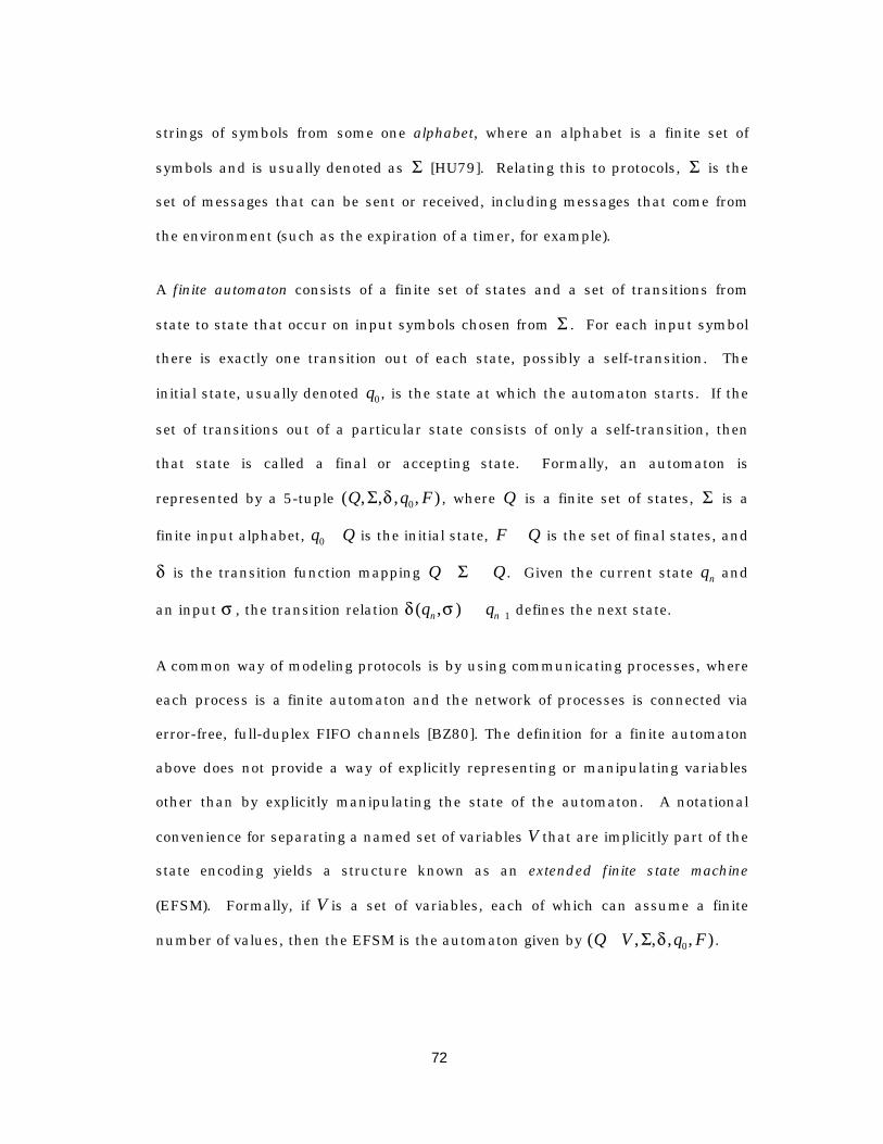
72
strings of symbols from some one alphabet, where an alphabet is a finite set of
symbols and is usually denoted as S [HU79]. Relating this to protocols, S is the
set of messages that can be sent or received, including messages that come from
the environment (such as the expiration of a timer, for example).
A finite automaton consists of a finite set of states and a set of transitions from
state to state that occur on input symbols chosen from S . For each input symbol
there is exactly one transition out of each state, possibly a self-transition. The
initial state, usually denoted q0 , is the state at which the automaton starts. If the
set of transitions out of a particular state consists of only a self-transition, then
that state is called a final or accepting state. Formally, an automaton is
represented by a 5-tuple ( , , , , )Q q FS d 0 , where Q is a finite set of states, S is a
finite input alphabet, q Q0 Œ is the initial state, F QÕ is the set of final states, and
d is the transition function mapping Q Q¥ ÆS . Given the current state qn and
an input s , the transition relation d s( , )q qn nÆ + 1 defines the next state.
A common way of modeling protocols is by using communicating processes, where
each process is a finite automaton and the network of processes is connected via
error-free, full-duplex FIFO channels [BZ80]. The definition for a finite automaton
above does not provide a way of explicitly representing or manipulating variables
other than by explicitly manipulating the state of the automaton. A notational
convenience for separating a named set of variables V that are implicitly part of the
state encoding yields a structure known as an extended finite state machine
(EFSM). Formally, if V is a set of variables, each of which can assume a finite
number of values, then the EFSM is the automaton given by ( , , , , )Q V q F¥ S d 0 .
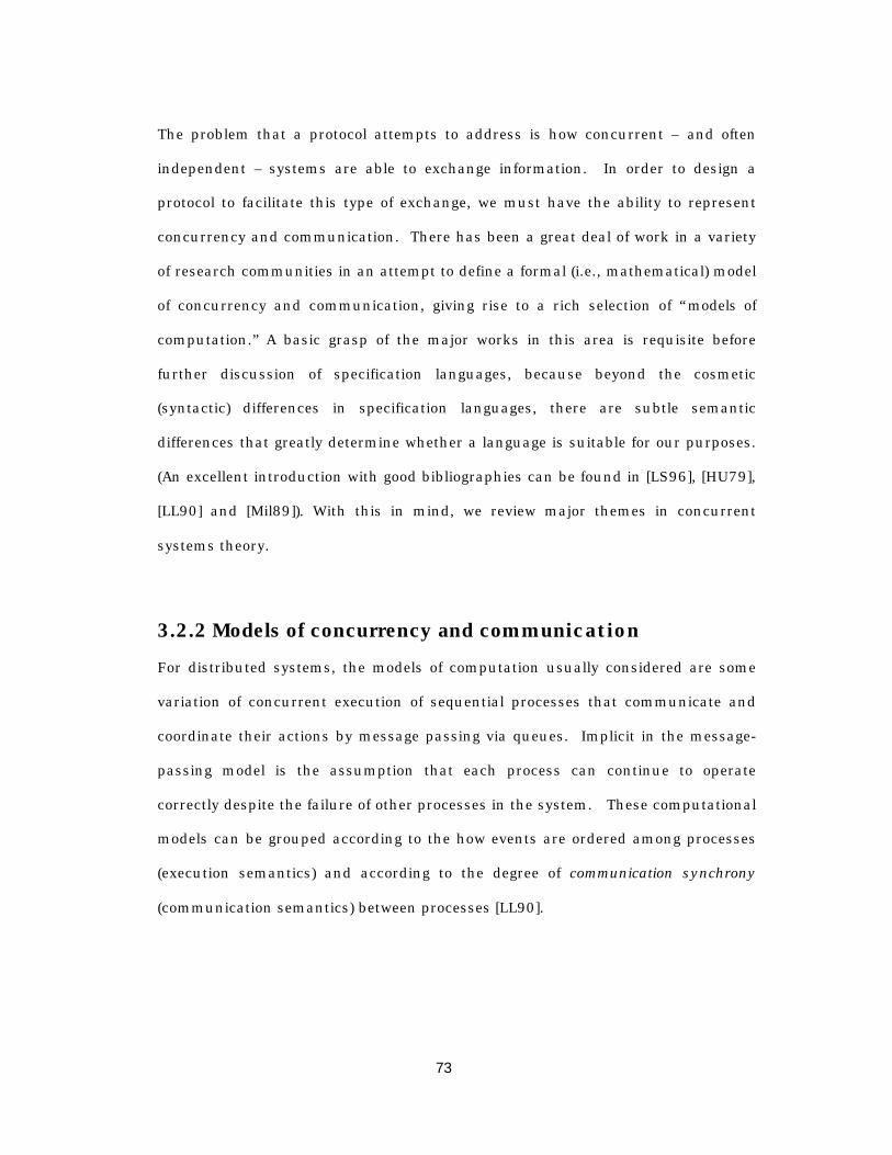
73
The problem that a protocol attempts to address is how concurrent – and often
independent – systems are able to exchange information. In order to design a
protocol to facilitate this type of exchange, we must have the ability to represent
concurrency and communication. There has been a great deal of work in a variety
of research communities in an attempt to define a formal (i.e., mathematical) model
of concurrency and communication, giving rise to a rich selection of “models of
computation.” A basic grasp of the major works in this area is requisite before
further discussion of specification languages, because beyond the cosmetic
(syntactic) differences in specification languages, there are subtle semantic
differences that greatly determine whether a language is suitable for our purposes.
(An excellent introduction with good bibliographies can be found in [LS96], [HU79],
[LL90] and [Mil89]). With this in mind, we review major themes in concurrent
systems theory.
3.2.2 Models of concurrency and communication
For distributed systems, the models of computation usually considered are some
variation of concurrent execution of sequential processes that communicate and
coordinate their actions by message passing via queues. Implicit in the message-
passing model is the assumption that each process can continue to operate
correctly despite the failure of other processes in the system. These computational
models can be grouped according to the how events are ordered among processes
(execution semantics) and according to the degree of communication synchrony
(communication semantics) between processes [LL90].

74
3.2.2.1 Semantics of event ordering
A natural question that arises when modeling a system of distributed interacting
processes is how the ordering of events is represented at the system level. Lee and
Sangiovanni-Vincentelli [LS96] present a framework for comparing models of
computation based on how time is represented. Their framework uses a tagged
signal model, where events consist of a (tag, value) pair and signals are simply sets
of events. Processes – fragments of the system – are relations on signals, which are
expressed as sets of n-tuples of signals. Models of computation are differentiated
according to how order imposed on tags and by how the process evolves [ELLV97].
Timed systems impose a total order on event tags, since given any two events it is
possible to say that either one preceded the other or that they occur
simultaneously. Untimed systems, where there is no assumed temporal relationship
between processes, are said to have partial order execution semantics. In these
systems, event tags within a process can be ordered, but ordering event tags
between processes is meaningless.
Asynchronous systems are untimed systems – for example, it is assumed that
messages that are inserted into a queue are eventually delivered. In asynchronous
systems, there is no concept of how long it takes the message to be delivered, how
fast a process executes relative to another process, how much time passes between
events, and there can be no assumption about when messages will arrive. However,
completely removing the notion of time is usually too strong for practical systems,
so other models introduce abstract time [ITU93a][Est89][Hol92]. Here it is possible
to specify that a message is to be delivered within some upper bound d that has no
correspondence to physical time, but creates a formal representation for a time-out
event and allows the specification to handle these events.
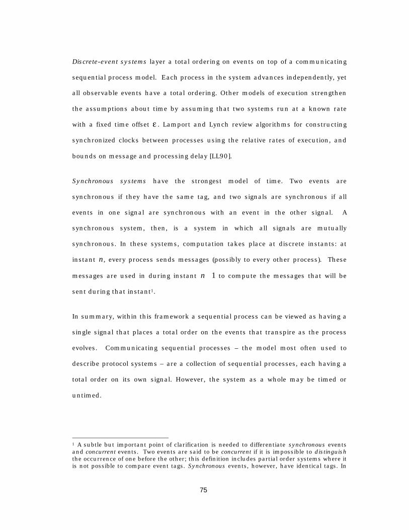
75
Discrete-event systems layer a total ordering on events on top of a communicating
sequential process model. Each process in the system advances independently, yet
all observable events have a total ordering. Other models of execution strengthen
the assumptions about time by assuming that two systems run at a known rate
with a fixed time offset e . Lamport and Lynch review algorithms for constructing
synchronized clocks between processes using the relative rates of execution, and
bounds on message and processing delay [LL90].
Synchronous systems have the strongest model of time. Two events are
synchronous if they have the same tag, and two signals are synchronous if all
events in one signal are synchronous with an event in the other signal. A
synchronous system, then, is a system in which all signals are mutually
synchronous. In these systems, computation takes place at discrete instants: at
instant n, every process sends messages (possibly to every other process). These
messages are used in during instant n + 1 to compute the messages that will be
sent during that instant1.
In summary, within this framework a sequential process can be viewed as having a
single signal that places a total order on the events that transpire as the process
evolves. Communicating sequential processes – the model most often used to
describe protocol systems – are a collection of sequential processes, each having a
total order on its own signal. However, the system as a whole may be timed or
untimed.
1 A subtle but important point of clarification is needed to differentiate synchronous eventsand concurrent events. Two events are said to be concurrent if it is impossible to distinguishthe occurrence of one before the other; this definition includes partial order systems where itis not possible to compare event tags. Synchronous events, however, have identical tags. In
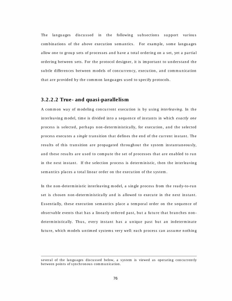
76
The languages discussed in the following subsections support various
combinations of the above execution semantics. For example, some languages
allow one to group sets of processes and have a total ordering on a set, yet a partial
ordering between sets. For the protocol designer, it is important to understand the
subtle differences between models of concurrency, execution, and communication
that are provided by the common languages used to specify protocols.
3.2.2.2 True- and quasi-parallelism
A common way of modeling concurrent execution is by using interleaving. In the
interleaving model, time is divided into a sequence of instants in which exactly one
process is selected, perhaps non-deterministically, for execution, and the selected
process executes a single transition that defines the end of the current instant. The
results of this transition are propagated throughout the system instantaneously,
and these results are used to compute the set of processes that are enabled to run
in the next instant. If the selection process is deterministic, then the interleaving
semantics places a total linear order on the execution of the system.
In the non-deterministic interleaving model, a single process from the ready-to-run
set is chosen non-deterministically and is allowed to execute in the next instant.
Essentially, these execution semantics place a temporal order on the sequence of
observable events that has a linearly ordered past, but a future that branches non-
deterministically. Thus, every instant has a unique past but an indeterminate
future, which models untimed systems very well: each process can assume nothing
several of the languages discussed below, a system is viewed as operating concurrentlybetween points of synchronous communication.
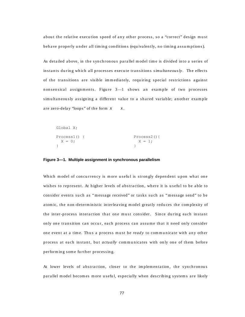
77
about the relative execution speed of any other process, so a “correct” design must
behave properly under all timing conditions (equivalently, no timing assumptions).
As detailed above, in the synchronous parallel model time is divided into a series of
instants during which all processes execute transitions simultaneously. The effects
of the transitions are visible immediately, requiring special restrictions against
nonsensical assignments. Figure 3— 1 shows an example of two processes
simultaneously assigning a different value to a shared variable; another example
are zero-delay “loops” of the form x x= ÿ .
Global X;
Process1() { X = 0;}
Process2(){ X = 1;}
Figure 3— 1. Multiple assignment in synchronous parallelism
Which model of concurrency is more useful is strongly dependent upon what one
wishes to represent. At higher levels of abstraction, where it is useful to be able to
consider events such as “message received” or tasks such as “message send” to be
atomic, the non-deterministic interleaving model greatly reduces the complexity of
the inter-process interaction that one must consider. Since during each instant
only one transition can occur, each process can assume that it need only consider
one event at a time. Thus a process must be ready to communicate with any other
process at each instant, but actually communicates with only one of them before
performing some further processing.
At lower levels of abstraction, closer to the implementation, the synchronous
parallel model becomes more useful, especially when describing systems are likely
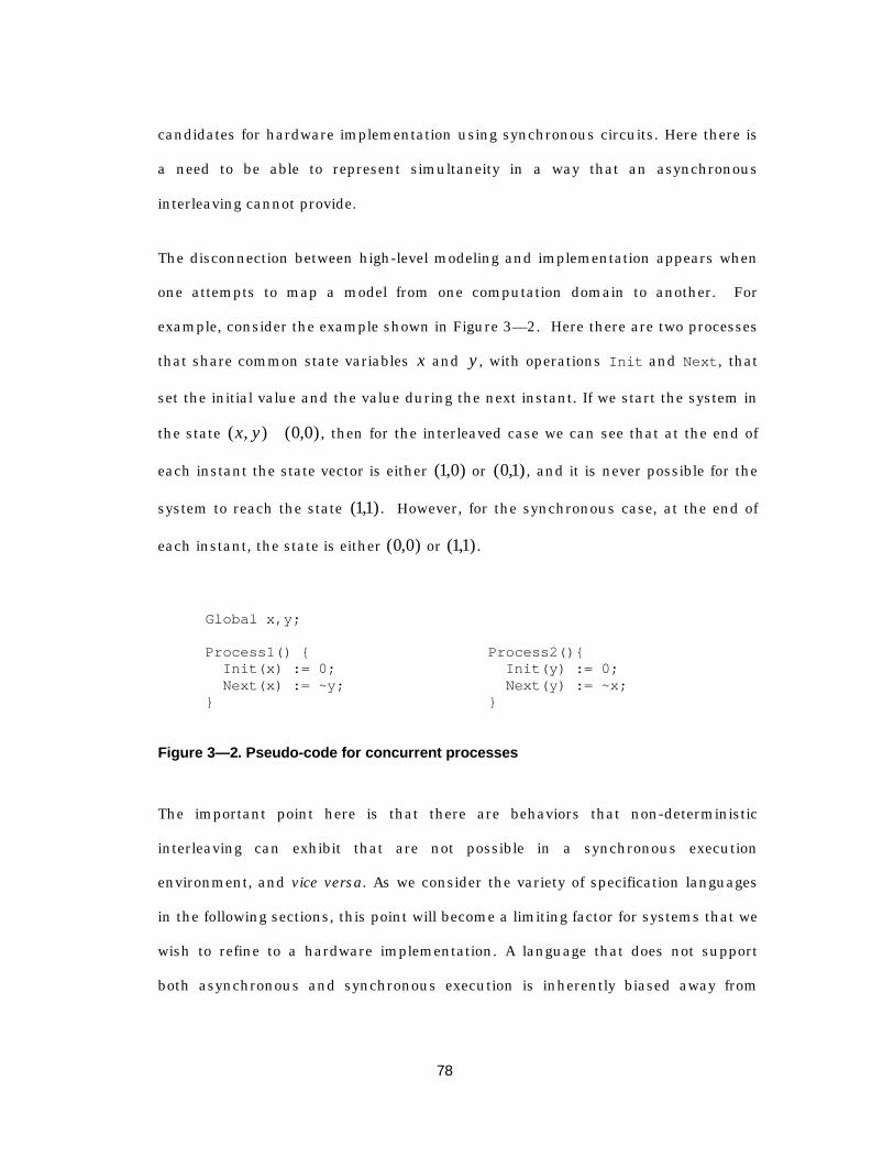
78
candidates for hardware implementation using synchronous circuits. Here there is
a need to be able to represent simultaneity in a way that an asynchronous
interleaving cannot provide.
The disconnection between high-level modeling and implementation appears when
one attempts to map a model from one computation domain to another. For
example, consider the example shown in Figure 3— 2. Here there are two processes
that share common state variables x and y , with operations Init and Next, that
set the initial value and the value during the next instant. If we start the system in
the state ( , ) ( , )x y = 0 0 , then for the interleaved case we can see that at the end of
each instant the state vector is either ( , )1 0 or ( , )01 , and it is never possible for the
system to reach the state ( , )11 . However, for the synchronous case, at the end of
each instant, the state is either ( , )0 0 or ( , )11 .
Global x,y;
Process1() { Init(x) := 0; Next(x) := ~y;}
Process2(){ Init(y) := 0; Next(y) := ~x;}
Figure 3— 2. Pseudo-code for concurrent processes
The important point here is that there are behaviors that non-deterministic
interleaving can exhibit that are not possible in a synchronous execution
environment, and vice versa. As we consider the variety of specification languages
in the following sections, this point will become a limiting factor for systems that we
wish to refine to a hardware implementation. A language that does not support
both asynchronous and synchronous execution is inherently biased away from

79
graceful refinement to synchronous hardware. The task of mapping a model in one
computation domain to another is one that is still an area of active research.
3.2.2.3 Communication Synchrony
A further point of differentiation in formal languages is the semantics of message
transfer, where the differentiation is made based on whether the sender must wait
on the receiver before continuing. Hoare’s language for communicating sequential
processes (CSP) [Hoa78] introduces a model where processes execute
asynchronously (in the sense that the relative rates of execution are not specified)
but communicate synchronously – a mechanism commonly referred to as a
rendezvous.
In CSP, processes execute asynchronously, but the message sending operation
requires the sender to wait for the receiver to accept the offered message before
proceeding to the next step in its execution. Thus, message passing defines
discrete synchronization points where the participants in a message exchange
execute simultaneously during the instant of message transfer. In the literature,
this style of communication is often referred to as a rendezvous between processes,
and, for example, is the communication that underlies remote procedure calls.
Asynchronous communication, on the other hand, allows the sender to post a
message to a queue and continue processing without waiting for the receiver to
accept the message. While this simplifies the description, it can lead to difficulties
during the implementation or validation phase because, for example, it is possible
to specify systems that require infinite buffering capacity, rendering many safety
and liveness properties formally undecidable. However, the asynchronous
80
communication using unrestricted queues is by far the most common abstraction
in protocol description languages, as we shall see in the following section.
3.2.3 Formal Languages for Protocol Specif ication
Since the models of computation usually considered are based on concurrent
execution of sequential processes, the primary function of a protocol specification is
to provide the legal execution sequences that each process can exhibit. Thus a very
natural way to think about and specify protocols is by using a language that is
based on concepts rooted in programming languages. In programming linguistics,
as in the study of natural languages, syntax is separated from semantics.
Language syntax is concerned with the structural aspects of the language, such as
the symbols and the phrases used to relate symbols; syntactic analysis determines
whether a program is legal. The semantics of a programming language, on the
other hand, deals with the meaning of a program – that is, what behavior is
produced when the program statements are executed.
In order to create an unambiguous specification, one must use a language that has
unambiguous semantics, so that a legal phrase in the language has a single
interpretation. In a protocol context, this requires an underlying mathematical
model of process execution, inter-process communication, and the system state
space. A language having these properties is known as a formal description
technique (FDT).
A variety of languages have been proposed and developed for the purpose of
describing protocols. Some of these languages were developed with the goal of
augmenting informal descriptions in protocols published by standards committees,
while others were developed as aids for the design and verification of protocols.

81
These languages can be differentiated according to the model of computation,
communication infrastructure, synchronization primitives, notion of time, and
support for data types. In sections 3.2.3.1 through 3.2.3.3, the most well known
formal languages are presented with a comparison of their suitability for protocol
specification.
3.2.3.1 Standardized FDTs for Protocol Spec ification
Several early attempts at developing a language formalizing a protocol description
[Ans86][ARC82][AC83] gave birth to three parallel standardization efforts by the
International Standards Organization (ISO) and Comité Consultatif International
Télégraphique et Téléphonique (CCITT). The resulting languages are described
below:
Estelle
Estelle [Est89][ISO9074] is a second generation FDT and was heavily influenced by
earlier prototype languages [Ans86][ARC82][AC83]. The underlying model is that of
extended finite state machines1 that communicate by exchanging messages and by
restricted sharing of some variables.
Model of computation: Estelle supports both non-deterministic interleaving and a
“synchronous parallel” model of computation, denoted by activities or processes,
respectively. The top-level construct, a specification, consists of a set of modules,
where the execution of each module is non-deterministically interleaved with that
1 “Extended” finite state machines do not treat variables as part of the state per se: instead ofhaving an explicit state and transition for each value of a variable, there is a many-to-one

82
of all other modules and the communication between top-level modules, called
systems, is asynchronous. A system must be attributed as either of the activity
type (systemactivity) or the process type (systemprocess). A systemactivity can
consist only of activity instances, while a systemprocess, on the other hand, can
consist of both activity and process instances. The legal parent-child relationships
are depicted in Figure 3— 3.
systemprocess systemactivity
process
process
activity
activity
activity
activity
activity
activity
activity
activity
module
Figure 3— 3. Estelle concurrency constructs
mapping between variable values and states. This is strictly a notational convenience that isused to clarify the design of a transition system.
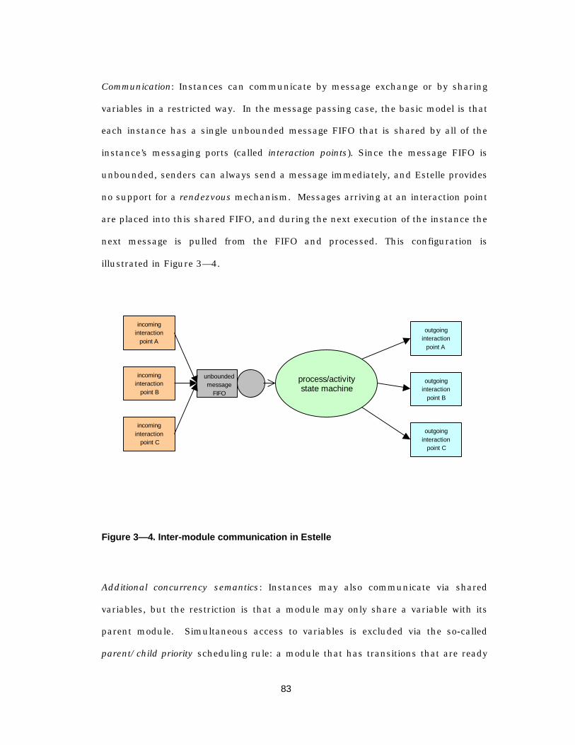
83
Communication: Instances can communicate by message exchange or by sharing
variables in a restricted way. In the message passing case, the basic model is that
each instance has a single unbounded message FIFO that is shared by all of the
instance’s messaging ports (called interaction points). Since the message FIFO is
unbounded, senders can always send a message immediately, and Estelle provides
no support for a rendezvous mechanism. Messages arriving at an interaction point
are placed into this shared FIFO, and during the next execution of the instance the
next message is pulled from the FIFO and processed. This configuration is
illustrated in Figure 3— 4.
process/activitystate machine
incominginteraction
point A
incominginteraction
point B
incominginteraction
point C
outgoinginteraction
point A
outgoinginteraction
point B
outgoinginteraction
point C
unboundedmessage
FIFO
Figure 3— 4. Inter-module communication in Estelle
Additional concurrency semantics: Instances may also communicate via shared
variables, but the restriction is that a module may only share a variable with its
parent module. Simultaneous access to variables is excluded via the so-called
parent/child priority scheduling rule: a module that has transitions that are ready
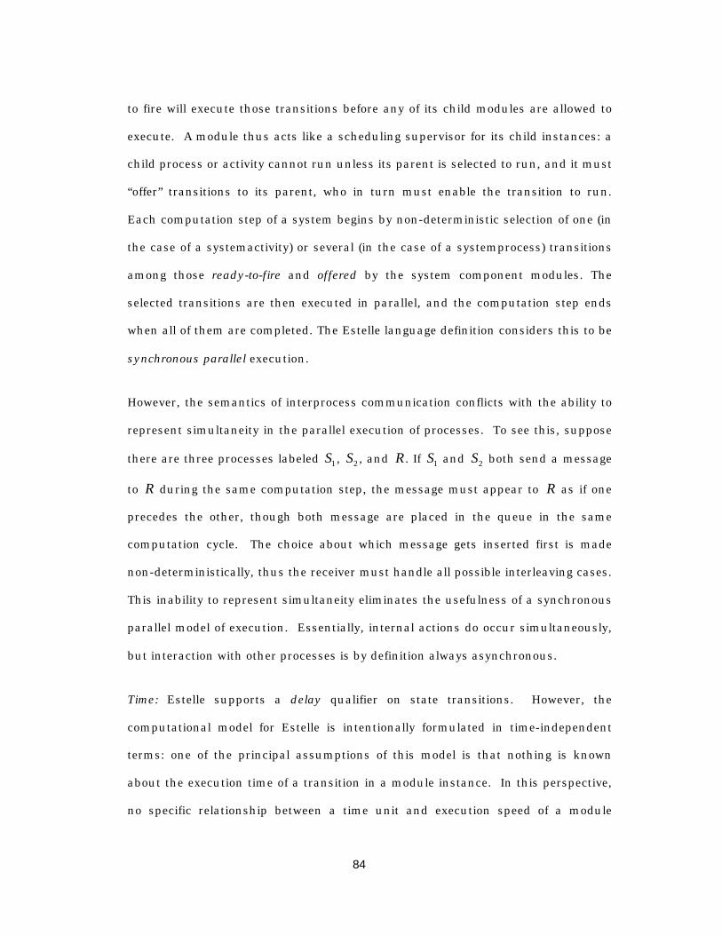
84
to fire will execute those transitions before any of its child modules are allowed to
execute. A module thus acts like a scheduling supervisor for its child instances: a
child process or activity cannot run unless its parent is selected to run, and it must
“offer” transitions to its parent, who in turn must enable the transition to run.
Each computation step of a system begins by non-deterministic selection of one (in
the case of a systemactivity) or several (in the case of a systemprocess) transitions
among those ready-to-fire and offered by the system component modules. The
selected transitions are then executed in parallel, and the computation step ends
when all of them are completed. The Estelle language definition considers this to be
synchronous parallel execution.
However, the semantics of interprocess communication conflicts with the ability to
represent simultaneity in the parallel execution of processes. To see this, suppose
there are three processes labeled S1 , S2 , and R . If S1 and S2 both send a message
to R during the same computation step, the message must appear to R as if one
precedes the other, though both message are placed in the queue in the same
computation cycle. The choice about which message gets inserted first is made
non-deterministically, thus the receiver must handle all possible interleaving cases.
This inability to represent simultaneity eliminates the usefulness of a synchronous
parallel model of execution. Essentially, internal actions do occur simultaneously,
but interaction with other processes is by definition always asynchronous.
Time: Estelle supports a delay qualifier on state transitions. However, the
computational model for Estelle is intentionally formulated in time-independent
terms: one of the principal assumptions of this model is that nothing is known
about the execution time of a transition in a module instance. In this perspective,
no specific relationship between a time unit and execution speed of a module
85
instance can be known or taken into account. The only assumptions about time are
that (a) time progresses as the computation does and (b) this progression is
uniform with respect to delay values of transitions. Thus, given two enabled
transitions whose delay timers are active (i.e., the transitions will be enabled to
execute when a specified delay has expired), at the beginning of the next
computation instant their delay values would decrease by the same amount
[Dem89].
SDL
The Specification and Description Language (SDL) [ITU93a][ITU93b] was developed
by the CCITT, and was designed specifically for the specification and design of
telecommunications systems. Started in 1968, SDL was accepted as an
international standard in 1987; ongoing work to add object-oriented constructs to
the language resulted in a revision in 1992 (SDL-92). Today it is the most widely
used and accepted of the FDTs, as evidenced by the commercially available tool
suites and the publication of several new international protocol standards with an
SDL specification [IEEE97][ETSI95][ETSI96].
Model of Computation: As in Estelle, SDL is based on an extended finite state
machine framework. A top-level system is composed of blocks, which are in turn
composed of processes, which are the actual state machines. Each process is a
state machine that executes by waiting in a state until an enabling condition exists
that allows it to transition to the next state. These transitions can include actions
such as modifying local variables and sending messages, but are modeled as if they
occur in zero time. Processes execute asynchronously and independently, and can
make no assumptions about the relative execution speed of other processes or
about the arrival order of signals, and thus have partial order execution semantics.
86
Communication: SDL processes communicate by sending signals via zero-delay
signalroutes (for inter-process communication) or arbitrary-delay channels for inter-
block communication. Normally, communication between processes is
asynchronous and, as in Estelle, a process has a single unbounded queue that is
shared between all incoming signalroutes. Arriving signals are placed in the queue
in the order of arrival, and two signals that arrive simultaneously are placed in the
queue in arbitrary order. Thus, all possible interleavings of arriving signals must
be considered.
The remote procedure call provides a mechanism for synchronous communication
by using exchange of signals of signals between the “server” process and the
“client” process. The requesting process (the client) sends a signal containing the
actual parameters of the procedure call, to the server process and waits for the
reply. In response to this signal, the server process executes the corresponding
remote procedure, sends a signal back to the requesting process with the value of
all in/out -parameters, and then executes the transition. . These signals are
implicit and are conveyed on implicit channels and signal routes.
A rather non-intuitive property of SDL communication is that, by default, SDL
handles unspecified reception by implicitly consuming unexpected signals. For
example, suppose the set of all possible incoming messages is { , , , }A B C D . If the
process is in a state where it is waiting for a signal from the set { , }A B , then all
occurrences of C or D are discarded until an A or Barrives. There is a
mechanism by which unanticipated signals can be saved on the input queue, thus
allowing FIFO ordering to be overridden, but this is not the default behavior.
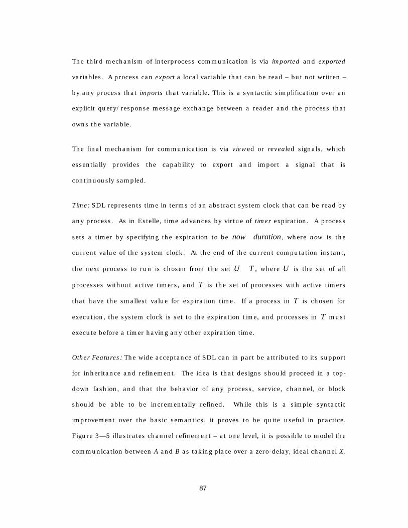
87
The third mechanism of interprocess communication is via imported and exported
variables. A process can export a local variable that can be read – but not written –
by any process that imports that variable. This is a syntactic simplification over an
explicit query/response message exchange between a reader and the process that
owns the variable.
The final mechanism for communication is via viewed or revealed signals, which
essentially provides the capability to export and import a signal that is
continuously sampled.
Time: SDL represents time in terms of an abstract system clock that can be read by
any process. As in Estelle, time advances by virtue of timer expiration. A process
sets a timer by specifying the expiration to be now duration+ , where now is the
current value of the system clock. At the end of the current computation instant,
the next process to run is chosen from the set U T» , where U is the set of all
processes without active timers, and T is the set of processes with active timers
that have the smallest value for expiration time. If a process in T is chosen for
execution, the system clock is set to the expiration time, and processes in T must
execute before a timer having any other expiration time.
Other Features: The wide acceptance of SDL can in part be attributed to its support
for inheritance and refinement. The idea is that designs should proceed in a top-
down fashion, and that the behavior of any process, service, channel, or block
should be able to be incrementally refined. While this is a simple syntactic
improvement over the basic semantics, it proves to be quite useful in practice.
Figure 3— 5 illustrates channel refinement – at one level, it is possible to model the
communication between A and B as taking place over a zero-delay, ideal channel X.
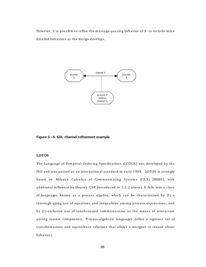
88
However, it is possible to refine the message-passing behavior of X to include more
detailed behaviors as the design develops.
processA
processB
process C(refines
channel X)
channel X
Figure 3— 5. SDL channel refinement example
LOTOS
The Language of Temporal Ordering Specifications (LOTOS) was developed by the
ISO and was passed as an international standard in early 1989. LOTOS is strongly
based on Milner’s Calculus of Communicating Systems (CCS) [Mil89], with
additional influence by Hoare’s CSP (introduced in 3.2.2 above). It falls into a class
of languages known as a process algebra, which can be characterized by (1) a
thorough-going use of equations and inequalities among process expressions, and
by (2) exclusive use of synchronized communication as the means of interaction
among system components. Process-algebraic languages define a rigorous set of
transformations and equivalence relations that allows a designer to reason about
behaviors.
89
LOTOS, though accepted as an international standard, has in practice gained little
acceptance and use. The highly mathematical way of reasoning and proving
equivalence relations proves to be unwieldy for large, real-world designs.
Model of Computation: As in both SDL and Estelle, LOTOS is based on
communicating extended finite state machines, called processes. The execution of
the EFSMs occurs via non-deterministic interleaving. Events are considered to be
atomic, and the parallel execution of two events aand b is defined as a situation of
choice, where either aoccurs before bor vise-versa.
Communication: As with all of the process algebraic languages, LOTOS provides
only for synchronous communication between processes. The sending process
must wait for the receiving process before continuing with computation; likewise, a
receiver must wait for a sender before continuing. It is possible to model
asynchronous communication by inserting queues between communicating
processes; these queues are themselves represented using processes.
LOTOS provides several synchronization primitives that are not found in either SDL
or Estelle. Mulitway synchronization, borrowed from CSP, allows a number of
processes to rendezvous. Anonymous synchronization allows a process to propose a
synchronization to its environment without being able to dirct its proposal to a
specific process; the (static) structure of the systems determines which process will
have to participate in the synchronization. Finally, non-deterministic
synchronization allows the system to non-deterministically choose the processes
involved in a given synchronization.
Time: LOTOS does not provide for a notion of time.

90
3.2.3.2 Specialized Languages
Several languages that are specifically directed toward the verification problem
have been developed and proposed by some as languages for formal specification.
Promela [Hol92], Murf [DDH92], and SMV [McM93] are three languages that
evolved as front-end specification languages for formal verification systems.
Semantically, Promela and Murf are not significantly different than the other EFSM
formalisms presented in the preceding section in that they both use non-
deterministic interleaving to model concurrency. However, they do have syntactical
properties that are tailored for formal verification. Both of these languages have
been used to demonstrate verification of simple communication protocols, but their
main area of application has been in verifying cache coherence protocols.
MurpfMurf, (pronounced “Murphi”) on the other hand, treats the system state as a
globally-shared vector, and defines rulesets that consist of an arbitrary number of
actions, define the rules for manipulating this global state. As in ProMela,
Murf employs a non-deterministic interleaving execution semantics, but the unit of
atomic execution is the ruleset rather than the individual statement.
PromelaIn ProMela (PROtocol MEta Language), sequential processes execute
asynchronously under a non-deterministic interleaving semantics, and
communicate either synchronously or asynchronously via finite-length queues. The
basic unit of atomic execution is an individual statement, though there are
provisions for aggregating statements as atomic actions. The state of the system is
91
composed of the local variables in each process, the contents of all queues, and the
program counters for each process.
The model of execution is untimed, though a timeout event can be specified to
occur whenever all of the other system queues are empty and no process can send
a new message. However, completely removing the concept of time increases the
complexity of the modeling system relative to a language such as SDL that provides
a mechanism for specifying the duration of timers.
This inability to distinguish between "fast" and "slow" timeouts proves to be the
most difficult aspect of using Promela as an early-prototyping language that
The strength of Promela as a modeling tool is that it is simple to define
communicating systems of finite state machines that can be formally verified for
safety, liveness, and other properties specified as linear temporal logic formulae.
SMVSMV, the front-end language for the SMV model checker, is an extremely elegant,
syntactically concise language that supports almost all execution semantic features
required for designing and specifying communication protocols. It supports both
synchronous and non-deterministically interleaved execution. However, its
communication semantics were born out of a hardware circuit environment, thus
its signaling mechanisms are modeled after hardware communication signals, so it
is not especially convenient for high-level modeling message exchange, since
timers, queues, and message exchange must be handled at the signal level.
Although in its current form it is not well-suited for use as a high-level, distributed-
systems language, it is appropriate for use in the implementation phase. In fact, it
92
is perhaps the best choice for an implementation language because of its formal
semantics and close ties to the verification tools. We will give an extended
introduction to SMV
3.2.3.3 The Synchronous Languages
We mention synchronous languages [Hal93) here only because they have been
extensively used for modeling systems of finite state machines. The underlying
assumption – the synchrony hypothesis – is that all processes view at exactly the
same instant. For implementing portions of a protocol, this model may be an
adequate representation of a particular implementation. However, because
protocols deal with systems that are distributed, the synchronous hypothesis is
inappropriate for describing the interaction relationships of distributed
components.
3.2.4 Summary of Formal Languages
Table 3— 1 presents a summary of the various formal languages presented in the
preceding sections. An evaluation of these languages resulted in using SDL as the
choice for high-level “message-passing” protocol design, and SMV as the language
for use in synchronous systems.
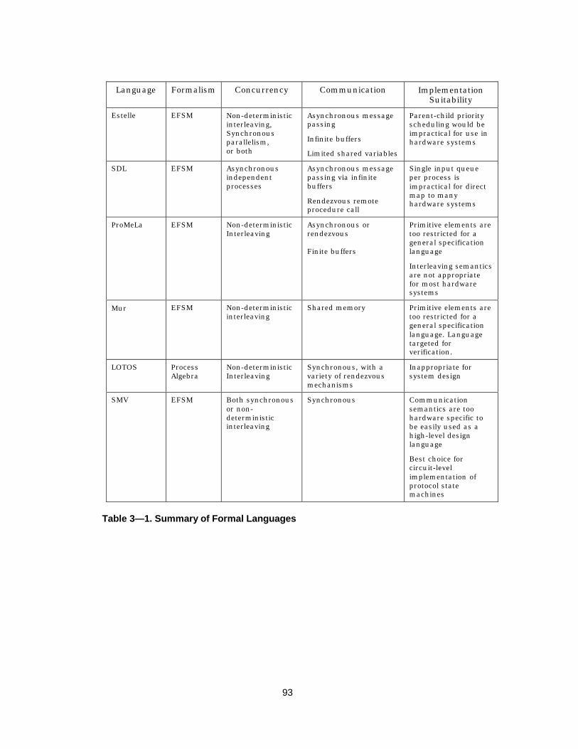
93
Language Formalism Concurrency Communication ImplementationSuitability
Estelle EFSM Non-deterministicinterleaving,Synchronousparallelism,or both
Asynchronous messagepassing
Infinite buffers
Limited shared variables
Parent-child priorityscheduling would beimpractical for use inhardware systems
SDL EFSM Asynchronousindependentprocesses
Asynchronous messagepassing via infinitebuffers
Rendezvous remoteprocedure call
Single input queueper process isimpractical for directmap to manyhardware systems
ProMeLa EFSM Non-deterministicInterleaving
Asynchronous orrendezvous
Finite buffers
Primitive elements aretoo restricted for ageneral specificationlanguage
Interleaving semanticsare not appropriatefor most hardwaresystems
Murf EFSM Non-deterministicinterleaving
Shared memory Primitive elements aretoo restricted for ageneral specificationlanguage. Languagetargeted forverification.
LOTOS ProcessAlgebra
Non-deterministicInterleaving
Synchronous, with avariety of rendezvousmechanisms
Inappropriate forsystem design
SMV EFSM Both synchronousor non-deterministicinterleaving
Synchronous Communicationsemantics are toohardware specific tobe easily used as ahigh-level designlanguage
Best choice forcircuit-levelimplementation ofprotocol statemachines
Table 3— 1. Summary of Formal Languages
94
Chapter 4
P r a c t i c a l A p p r o a c h e s t o t h eF o r m a l V e r i f i c a t i o n o f
C o m m u n i c a t i o n P r o t o c o l s
4.1 Overview of formal verification
Protocol design is error prone because it involves designing distributed concurrent
systems and that must behave correctly under all conditions. Pnueli, in a seminal
paper [Pnu77], argued that a special type of modal logic1 called temporal logic could
be a useful formalism for specifying and verifying correctness of computer
programs, especially for “reactive” systems that continuously interact with their
environment. Temporal logic provides operators that allow one to reason about how
the truth of an assertion varies with time. For example, eventually Q is true if there
1 Modal logic was originally developed by philosopers to study different “modes” of truth. Forexample, the assertion P may be false in the present world, yet the assertion possibly P maybe true if there exists an alternate world where P is true [Eme90].
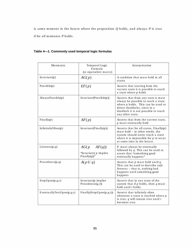
95
is some moment in the future where the proposition Q holds, and always P is true
if for all moments P holds.
Table 4— 1. Commonly used temporal logic formulas
Mnemonic Temporal LogicFormula
(or equivalent macro)
Interpretation
Invariant(p) AG p( ) A condition that must hold in allstates
Possible(p) EF p( ) Asserts that starting from thecurrent state it is possible to reacha state where p holds
AlwaysPossible(p) Invariant(Possible(p)) Asserts that from any state it mustalways be possible to reach a statewhere p holds. This can be used todetect deadlocks, since in adeadlock it is not possible to reachany other state.
Finally(p) AF p( ) Asserts that from the current state,p must eventually hold
InfinitelyOften(p) Invariant(Finally(p)) Asserts that for all states, Finally(p)must hold – in other words, thesystem should never reach a statewhere it is impossible for p to occurat some time in the future.
Liveness(p,q) AG p AF q( ( ))fi“Invariant( p impliesFinally(q))”
P must always be eventuallyfollowed by q. This can be used toassert that “something goodeventually happens”
Precedence(p,q) A p U q( ) Asserts that p must hold until q.This can be used to describe safeliveness – that is, nothing badhappens until something goodhappens
StopUpon(p,q,r) Invariant(p impliesPrecedence(q,r))
Asserts that in any state of thesystem that if p holds, then q musthold until r holds.
EventuallyTestUpon(p,q,r) Finally(StopUpon(p,q,r)) Asserts that infinitely oftenwhenever a state is reached where pis true, q will remain true until rbecomes true.

96
Before this application of temporal logic, proving the correctness of sequential
programs was approached using Hoare’s Logic. Here, correctness is formulated in
terms of initial- and final-state properties that must hold before and after
execution, respectively. Under this method of proof, a program is said to be correct
if given the correct initial state, the program terminates in the proper final state.
However, protocol systems are reactive in that they must continually respond to
stimulus that comes from the environment, so it is difficult to reason in terms of
“final states.” Pnueli’s contribution was the realization that temporal logic operators
provide a formalism that can adequately handle the non-terminating behavior of
reactive systems.
Historically, the application of temporal logic to reasoning about concurrent
distributed systems can grouped into two broad categories: proof-theoretic
techniques and model-theoretic techniques. Informally, the proof approach relies
on the basic idea that the system model (what the system is) and specification (what
the system is supposed to do) can be expressed as a collection of logical
propositions, axioms, and inference rules, and the task is to prove that the model
implies the specification. The most serious limitation of this approach is that it is
too far removed from practicable design styles: for a reasonably sized system, the
hundreds of lemmas must be proved in full detail to render this approach valid.
For this reason, theorem proving in general is not a serious candidate for proving
properties of real systems.
The model-theoretic approach uses the global state transition graph of a finite state
concurrent system as a finite temporal logic structure, and a model-checking
algorithm is applied to determine if the structure is a model of a specification
expressed as a temporal logic formula. Thus, the model checking algorithm is able

97
to determine if a given finite-state program meets a particular correctness
specification.
Recent work by McMillan, termed compositional refinement verification, uses a
combination of theorem-proving and model-theoretic techniques. By exploiting
symmetry that is common in many designs, it simplifies the proof technique as well
as offering the possibility of handling larger designs. Compositional refinement
verification forms the basis for relating a high-level specification to an
implementation in our design methodology and will be explored in the next chapter.
At the moment, we take a brief tour of the main efforts in formal verification and
consider their applicability to a protocol design methodology.
4.2 Model Checking
The most well developed tools use a technique known as model checking, where
invariants and temporal propositions can be checked by traversing the state space.
McMillan’s SMV symbolic model checking system [McM93], Holzmann’s Spin
[Hol92], and AT&T’s COSPAN fall into this category.
Model checking is suitable for full automation yet is limited to systems that can be
modeled as a finite state machine (the model). A specification, written as a set of
temporal logic formulae, is taken together with a finite state machine, and the job
of the tool is to show that the behavior of the model implies the specification. An
automated model checker can simply traverse the state space and find a state in
which some part of the specification is violated, and can produce the execution
trace of the counter example by stepping the execution back to an initial state.
98
Though the expressiveness of temporal logic is somewhat limited when compared to
the power of general theorem proving, many properties central to designing sound
communication protocols (safety, liveness, fairness, etc.) can be handled quite well
[McM92]. However, both the strength and limitation of automated model checkers
is that they are based on exhaustive reachability analysis. To establish the truth or
state invariants, it suffices to verify that in each state that is reachable from an
initial state, the invariants hold [Hol92]. Inevitably, however, one must face the
unfortunate property of finite state systems: the state explosion problem, which is
the exponential relationship between the number of states in the model to the size
of the state vector required to capture the state of the system. (The largest systems
that have been checked to date have are on the order of 1020 states, corresponding
to about 64 bits of state.)
The size of the state vector depends on several factors. Obviously, the number of
explicit variables in each process (i.e., state machine), and the range of values
assumed by each variable is a factor. The number of queues, the length of the
queues, and the size of each queue entry is also a factor.
But, more subtly, the granularity of atomic execution has perhaps the most
dramatic influence on the number of possible states that the system can visit.
Informally, all possible interleavings of atomic events must be verified, so that
increasing the granularity of atomicity has a dramatic impact on the number of
executions the system can realize.
For this reason, actors in the protocol must be modeled at a very high level of
abstraction in order to keep the size of the problem within reach of automated
99
tools, excluding the checking a fully detailed implementation for all but the
simplest of systems.
In the following subsections, we explore the various techniques that have been
applied to cope with the computational complexity of formally verifying concurrent
systems.
4.2.1 Symbolic Model Checking
Arguably, the biggest advancement in reducing the limitations imposed by the state
explosion problem was made with the advent of symbolic model checking [McM93].
The SMV system designed by McMillan uses symbolic model checking to verify
synchronous systems. McMillan’s contribution to the field came from the
realization that ordered binary decision diagrams (OBDDs) [Bry86] could be used to
avoid explicitly representing the transition relation. Instead, the transition function
encoded as functions on sets of Boolean variables.
The basic symbolic model checking algorithm translates the specification and the
model into temporal logic formulae that subsequently translated to a fixed-point
representation. The algorithm calculates these fixed points by performing
operations on the OBDD that represents the transition relation. After each
iteration, the result is again an OBDD, so that the system state graph need never
be explicitly constructed. For systems where there is some regularity, the OBDD
representation of the system can be very compact.
However, in systems where the mutual information between variables is small, the
OBDD approach breaks down, leaving us again searching for ways to reduce the
state space.

100
4.2.2 Partial Order Reduction
A second technique to cope with the state space explosion problem tries to directly
reduce the number of observable states by clustering independent events into
equivalence classes in which the order of execution is indistinguishable.
As mentioned in Section 3.2.2.2, interleaving observable events can be used to
model concurrency. Since interleaved semantics places a total order on the events
that occur during an execution of the system, given any pair of events a and b, it is
possible to say that either a precedes b or b precedes a. Interleaving semantics are
simple and are strongly connected to a well-developed body of work on automata
theory, and for this reason most model checking systems use interleaving
semantics to model concurrency. Formally verifying a totally ordered semantics
model requires the system to consider all possible interleavings of events.
Recently, much attention has been given to modeling concurrent systems using
partial order execution semantics [Pra86][AM97]. In concurrent systems, events are
often independent, so that trying to impose a total order on the execution is far too
strong a statement. For example, given the set {graduation,marriage,death}, it is
possible to say that both graduation and marriage must occur before death, but
since graduation and marriage are independent events, it is meaningless to insist
that one must precede the other. Thus, using the notation < to indicate
precedence, we can only infer
marriage deathgraduation death
<<
Partial order semantics offer a more intuitive representation of the executions of a
concurrent system by allowing independent events to be identified and reordered
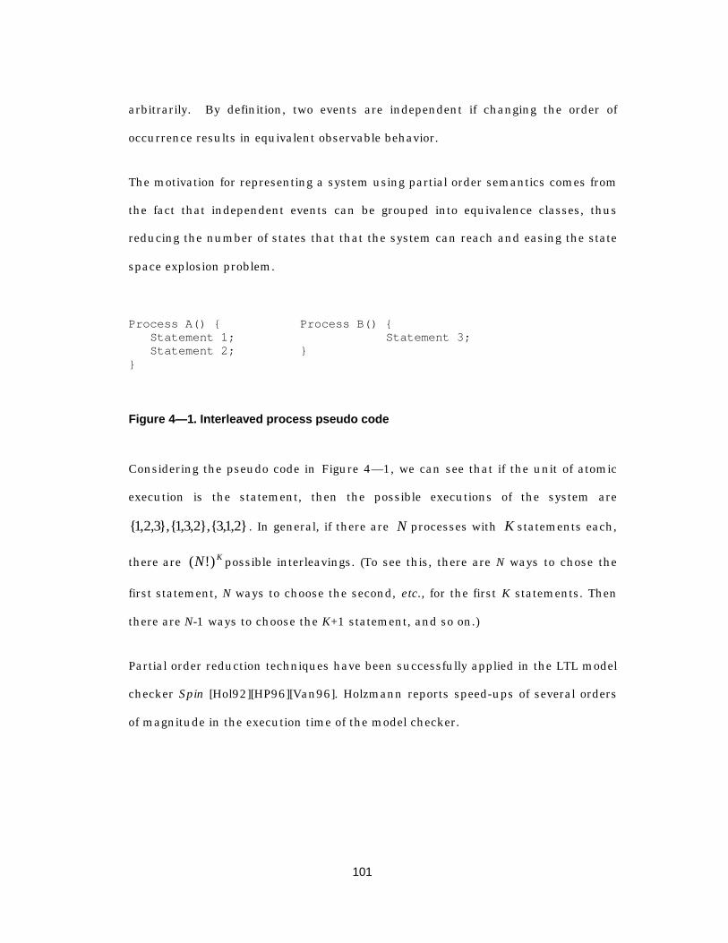
101
arbitrarily. By definition, two events are independent if changing the order of
occurrence results in equivalent observable behavior.
The motivation for representing a system using partial order semantics comes from
the fact that independent events can be grouped into equivalence classes, thus
reducing the number of states that that the system can reach and easing the state
space explosion problem.
Process A() { Process B() {Statement 1; Statement 3;Statement 2; }
}
Figure 4— 1. Interleaved process pseudo code
Considering the pseudo code in Figure 4— 1, we can see that if the unit of atomic
execution is the statement, then the possible executions of the system are
{ , , },{ , , },{ , , }1 2 3 13 2 31 2 . In general, if there are N processes with K statements each,
there are KN )!( possible interleavings. (To see this, there are N ways to chose the
first statement, N ways to choose the second, etc., for the first K statements. Then
there are N-1 ways to choose the K+1 statement, and so on.)
Partial order reduction techniques have been successfully applied in the LTL model
checker Spin [Hol92][HP96][Van96]. Holzmann reports speed-ups of several orders
of magnitude in the execution time of the model checker.
102
4.2.3 Symmetry Reduction
A third mechanism, pioneered by Ip and Dill [ID93] is to use symmetry inherent in
many systems to reduce the size of the state space. The basic idea is to chose a
representative case from an equivalence class and perform the verification for that
representative case. Using the symmetry of the design, the result of the verification
can be extended to all members of the equivalence class.
An example we will consider in Chapter 5 makes heavy use of symmetry to prove
properties about a packet switching circuit. The basic system in this example
consists of N data sources feeding packets into a switched, a single word at a time.
The words from each data source may be interleaved during their entry into the
switch, but we would like to prove that at the output of the switch the data comes
out in the correct order and that the packets emitted from the switch were actually
transmitted by one of the N sources.
Using symmetry, we can verify the desired properties for a single bit of a single
word of a single packet of a single data source. This is because, within a given
word, all bits are symmetric: we are not concerned about the particular values or
bit-position, but want to say that the properties hold for all bits in a word.
Similarly, the words in a packet are symmetric in the sense that, independent of
the order in which they were transmitted, they all appear at the output and have
the correct value. (We would need to prove ordering separately.) We can extend this
argument to say that at some level, all of the N senders are equivalent.
By using symmetry, we can reduce the number of states that the system can be in
by many orders of magnitude. In the example in Chapter 5, for example, the packet
switch system was verified for 10 senders transmitting 128-word packets, with 64

103
bits per word. Without the use of symmetry, scaling the verification to handle a
practical system would be impossible.
4.2.4 Compositional Refinement Verification
Given the state-space explosion problem, there has long been the idea that design
should be approached top-down, moving from the abstract to the implementation.
Automated verification tools are envisioned to be the enabling link that allows the
designer to incrementally verify the design as implementation detail is added, so
that the final implementation is consistent with the abstract specification.
The compositional aspect comes from the idea that the design is decomposed into
small parts whose properties can be verified in isolation, and the final system is
taken as the composition of these elements. Properties that must hold for at the
system level are proven in terms of the properties of the individual elements, and a
compositional rule specifies exactly when the composition of properties can be used
to infer the properties of the entire system.
A compositional proof is usually build using the following reasoning. If P and Q are
processes, φ an assumption about the environment, and is the property that we
wish to prove then we must first show that given the environment assumption φ,
the property ψ holds in P, written as P, |φ ψ= . We must also show that the
environment assumption φ holds in Q, or Q |= φ. Then we can infer that the
composition of P and Q maintains the property ψ . This is written as
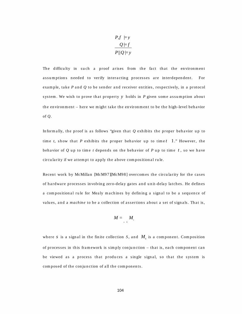
104
PQ
P Q
, ||
|| |
φ ψφψ
===
The difficulty in such a proof arises from the fact that the environment
assumptions needed to verify interacting processes are interdependent. For
example, take P and Q to be sender and receiver entities, respectively, in a protocol
system. We wish to prove that property ψ holds in P given some assumption about
the environment – here we might take the environment to be the high-level behavior
of Q.
Informally, the proof is as follows “given that Q exhibits the proper behavior up to
time t, show that P exhibits the proper behavior up to time t + 1 .” However, the
behavior of Q up to time t depends on the behavior of P up to time t , so we have
circularity if we attempt to apply the above compositional rule.
Recent work by McMillan [McM97][McM98] overcomes the circularity for the cases
of hardware processes involving zero-delay gates and unit-delay latches. He defines
a compositional rule for Mealy machines by defining a signal to be a sequence of
values, and a machine to be a collection of assertions about a set of signals. That is,
M MS
= ∧∈σ
σ
where σ is a signal in the finite collection S, and Mσ is a component. Composition
of processes in this framework is simply conjunction – that is, each component can
be viewed as a process that produces a single signal, so that the system is
composed of the conjunction of all the components.
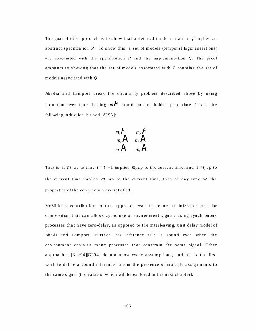
105
The goal of this approach is to show that a detailed implementation Q implies an
abstract specification P. To show this, a set of models (temporal logic assertions)
are associated with the specification P and the implementation Q. The proof
amounts to showing that the set of models associated with P contains the set of
models associated with Q.
Abadia and Lamport break the circularity problem described above by using
induction over time. Letting mA τ stand for “m holds up to time t = τ ”, the
following induction is used [AL93]:
m m
m m
m m
11
2
2 1
1 2
A ⇒ AA ⇒ AA ∧ A
−τ τ
τ τ
ω ω
That is, if m1 up to time t = −τ 1 implies m2 up to the current time, and if m2 up to
the current time implies m1 up to the current time, then at any time ω the
properties of the conjunction are satisfied.
McMillan’s contribution to this approach was to define an inference rule for
composition that can allows cyclic use of environment signals using synchronous
processes that have zero-delay, as opposed to the interleaving, unit delay model of
Abadi and Lamport. Further, his inference rule is sound even when the
environment contains many processes that constrain the same signal. Other
approaches [Kur94][GL94] do not allow cyclic assumptions, and his is the first
work to define a sound inference rule in the presence of multiple assignments to
the same signal (the value of which will be explored in the next chapter).

106
Without undue detail, the inference rule is presented here for completeness and to
lay the theoretical groundwork for the refinement techniques presented in Chapter
5. The reader is referred to [McM97][McM98] for the proof.
Let P and Q be a set of processes, and → a given well founded order on the signals
in P. We will call P the specification, and Q the implementation. If p p1 2→ , then
p2 depends on p1 , we use p1 A τ to prove p2 A τ , else we use p11A −τ . Define
Z Q p P p pp = ′∈ ′→U :l q
to be the set of processes that can be used to prove p with zero delay. Then to prove
a particular p up to the present timeτ , an arbitrary set of environment
assumptions ε p P Q⊆ U may be chosen, with those signals in Zp assumed up to
the present time, and the reset assumed up to the last instant τ − 1 . Then, with a
process understood to be the conjunction of its components, the following theorem
holds.
Theorem 1 [McM98]: For all p P∈ , choose ε p P Q⊆ U . The following inference rule
is sound:
for all p P p
Q P
p p p pcZ Z∈ A ∧ A ⇒
A ⇒ A−: ε ετ τ
ω ω
I Id i d i 1
In words, this says that for all p in P, if the environment assumptions taken up to
the appropriate time (depending on whether the assumed signal is in Zp ) implies p,
then the implementation implies the specification.
107
McMillan used this approach to verify Tomasulo’s algorithm using an automated
model checking system (SMV). In his example, the specification is a machine P that
executes instructions in order as they arrive, stalling non-deterministically before
emitting the answer. The implementation Q is a pipelined arithmetic unit that
executes a stream of operations on a register file. Tomasulo’s algorithm allows
execution of instructions in data-flow order, rather than sequential order, so that
the proof entails showing that the implementation produces the correct stream of
output answers. Combining this approach with symmetry reductions described in
the preceding section, it was possible to prove the system for 32-bit data, 16 32-bit
registers, and 16 32-bit reservation stations.
In the next chapter, we apply this technique to solve two problems. First, we would
like to relate an SDL model with asynchronous, atomic message-passing semantics
to a synchronous, sequential message transfer implementation. Second, we would
like to verify properties about our hardware implementation of data transfer
protocols. Due to the state space explosion problem, verifying properties about
large blocks of data moving through a system has to date been out of reach of
automated verification tools.

108
Chapter 5
A H a r d w a r eI m p l e m e n t a t i o n
Me thodo l ogy Us ingR e f i n e m e n t V e r i f i c a t i o n
5.1 Overview
The design methodology presented in this work has as its goal linking formal
specification to implementation. This chapter focuses on an approach by which it is
possible to refine a high-level finite state machine with large-granularity, atomic-
transfer message passing semantics to an implementation in synchronous
hardware where message transfers take place in a sequence of smaller
transactions. Further, the approach will allow us to formally verify the equivalence
of the high-level specification and the low-level implementation.
The basic problem is that the high level specification must be both time granularity
and behavioral detail. A state machine described in the SDL language, for example,
has execution semantics in which signals arrive instantaneously over channels
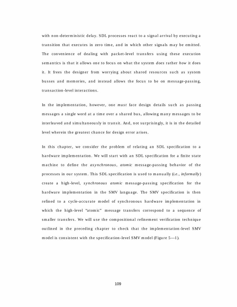
109
with non-deterministic delay. SDL processes react to a signal arrival by executing a
transition that executes in zero time, and in which other signals may be emitted.
The convenience of dealing with packet-level transfers using these execution
semantics is that it allows one to focus on what the system does rather how it does
it. It frees the designer from worrying about shared resources such as system
busses and memories, and instead allows the focus to be on message-passing,
transaction-level interactions.
In the implementation, however, one must face design details such as passing
messages a single word at a time over a shared bus, allowing many messages to be
interleaved and simultaneously in transit. And, not surprisingly, it is in the detailed
level wherein the greatest chance for design error arises.
In this chapter, we consider the problem of relating an SDL specification to a
hardware implementation. We will start with an SDL specification for a finite state
machine to define the asynchronous, atomic message-passing behavior of the
processes in our system. This SDL specification is used to manually (i.e., informally)
create a high-level, synchronous atomic message-passing specification for the
hardware implementation in the SMV language. The SMV specification is then
refined to a cycle-accurate model of synchronous hardware implementation in
which the high-level “atomic” message transfers correspond to a sequence of
smaller transfers. We will use the compositional refinement verification technique
outlined in the preceding chapter to check that the implementation-level SMV
model is consistent with the specification-level SMV model (Figure 5— 1).
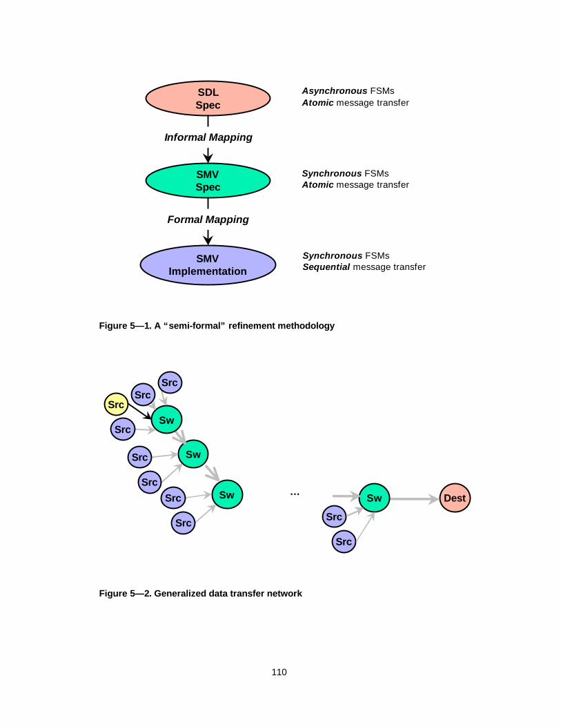
110
SDLSpec
SMVSpec
SMVImplementation
Formal Mapping
Informal Mapping
Asynchronous FSMsAtomic message transfer
Synchronous FSMsAtomic message transfer
Synchronous FSMsSequential message transfer
Figure 5— 1. A “semi-formal” refinement methodology
Sw
SrcSw
Sw Dest…
Src
Src
SrcSrc
Src
Src
Src Src
Src
Sw
Figure 5— 2. Generalized data transfer network
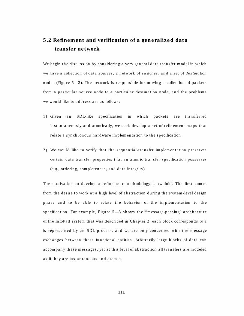
111
5.2 Refinement and verification of a generalized datatransfer network
We begin the discussion by considering a very general data transfer model in which
we have a collection of data sources, a network of switches, and a set of destination
nodes (Figure 5— 2). The network is responsible for moving a collection of packets
from a particular source node to a particular destination node, and the problems
we would like to address are as follows:
1) Given an SDL-like specification in which packets are transferred
instantaneously and atomically, we seek develop a set of refinement maps that
relate a synchronous hardware implementation to the specification
2) We would like to verify that the sequential-transfer implementation preserves
certain data transfer properties that an atomic transfer specification possesses
(e.g., ordering, completeness, and data integrity)
The motivation to develop a refinement methodology is twofold. The first comes
from the desire to work at a high level of abstraction during the system-level design
phase and to be able to relate the behavior of the implementation to the
specification. For example, Figure 5— 3 shows the “message-passing” architecture
of the InfoPad system that was described in Chapter 2: each block corresponds to a
is represented by an SDL process, and we are only concerned with the message
exchanges between these functional entities. Arbitrarily large blocks of data can
accompany these messages, yet at this level of abstraction all transfers are modeled
as if they are instantaneous and atomic.
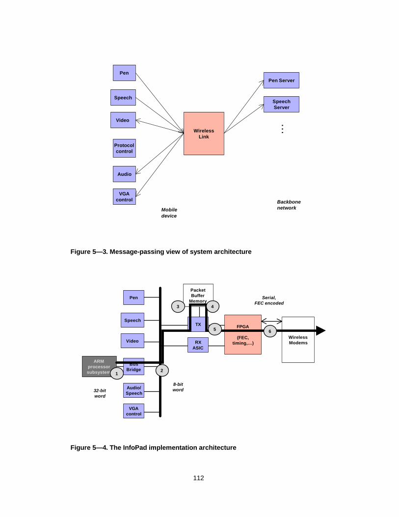
112
Protocolcontrol
Video
Pen
Speech
Audio
VGAcontrol
WirelessLink
Pen Server
SpeechServer
…
Mobiledevice
Backbonenetwork
Figure 5— 3. Message-passing view of system architecture
BusBridge
ARMprocessorsubsystem
RXASIC
FPGA
(FEC,timing,… )Video
Pen
SpeechTX
Audio/Speech
VGAcontrol
WirelessModems
32-bitword
8-bitword
Serial,FEC encoded
PacketBuffer
Memory
12
65
43
Figure 5— 4. The InfoPad implementation architecture

113
However, as we move toward implementation, our view of each functional entity
must include physical interfaces, data representations, and functional
transformations on the data. For example, the protocol control process in Figure
5— 3 maps onto a software process in the implementation architecture shown in
Figure 5— 4. Message transfers from the microprocessor to the physical wireless
link involve 6 interfaces and several encoding transformations. Thus, our first
objective is to establish a relationship between the implementation and the
specification.
The second motivation for developing a refinement methodology comes from the
fact that compositional refinement allows us to break the formal verification
problem into smaller sub-problems; without compositional refinement, the
enormous state space required to represent blocks of data eliminates this class of
problems from the realm of formal verification. A “large” formal verification problem
that can be handled by automatic tools is limited to about 220 states. As a means of
comparison, an N-bit data block introduces 2N states into the verification problem.
For example, for each interface, format transformation, and encoding
transformation shown in Figure 5— 4, we would like to verify that the data that is
fed into the wireless modem is what was actually intended. We would like know
that the implementation neither erroneously reorder bytes within a packet nor
mixes data from different packets.
Before proceeding, a word about relating systems under different models of
computation is in order. Since a computational model (e.g., asynchronous,
interleaved, synchronous, etc.) is by definition an abstraction, it presents a view of
the system that indicates both what a designer deems important and what the
114
designer is willing to ignore for the moment. At the SDL level, for example, one is
implicitly discarding the mechanics of message passing; in a synchronous
language, one discards the absolute measure of time between system ticks.
As outlined in 3.2.2, it is in general not possible to automatically map an
asynchronous system onto a synchronous system. Thus, it is not possible to
directly generate a synchronous hardware implementation from an SDL process
specification. Thus, we take the approach of using an informal mapping between an
asynchronous specification (SDL) and a high-level synchronous specification (SMV).
By preserving “instantaneous transfer” semantics in the synchronous specification,
we simplify the manual mapping procedure, reducing the chance of errors. The
instantaneous transfer specification can then be formally refined into a sequential
implementation using the techniques presented in the remainder of this chapter.
5.3 Zen and the art of protocol abstraction1
We define a token to be a (tag,value) pair {( , ): , }t v t T v V∈ ∈ , where T and V are
both finite sets. A packet is defined to be a finite collection of N tokens where for all
i j N, ∈ −0 1K where i j t ti j≠ ⇒ ≠ (i.e., the tags in a given packet are unique).
The problem at hand is to move a collection of packets from a source to a receiver
via an intermediate agent called a switch, whose job is to regulate and organize the
transfers. (For convenience, we will assign a unique identification tag to each
1 The title for this section was inspired by the combination of a conversation with KenMcMillan (in which he likened the highest level abstraction to a “Zen-like” approach:“packets exist.”) and a simultaneous reading of Zen and the Art of Motorcycle Maintenance
115
packet in the source, thus we denote the ith packet as the set
( , ), | |, ,t v k Ti k i k i∈ −0 1Km r .) The goal is to show that a packet that appears in the
receiver matches a packet in the source, without restricting the mechanism by
which the transfer occurs.
To show this, we can separate the problem of token integrity from token ordering
and packet completeness. Verifying token integrity amounts to showing for each
token tag at the receiver, the token value matches the corresponding token at the
sender. Completeness guarantees that all tokens in the source’s version of a packet
appear in the receiver’s version of the packet. Finally, the ordering problem is one of
showing that given a class of bijective ordering functions φ : | |T Ta K0 1− , that
φ φs r i it t− =1( ( )) , where φs is the order that the sender intents for the receiver to use.
In other words, we must show that the order that the receiver places on the tokens
is the same order that the sender uses.
5.3.1 A divide-and-conquer approach
The verification strategy will be to break this large system into a collection of
smaller systems that can be individually verified. We will use the compositional
verification techniques discussed in Chapter 4 (specifically, Theorem 1) to ensure
that the properties verified in the individual systems hold true in the composed
system.
Structurally, we will break the problem into a series of point to point transfers. We
will verify that transfers between the original data source and the first switch occur
correctly (i.e., data integrity, token ordering, and packet completeness hold). Next,
we verify that transfers from the first switch to the second occur correctly, and so
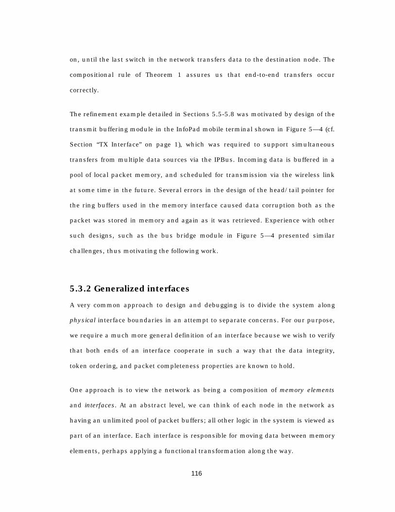
116
on, until the last switch in the network transfers data to the destination node. The
compositional rule of Theorem 1 assures us that end-to-end transfers occur
correctly.
The refinement example detailed in Sections 5.5-5.8 was motivated by design of the
transmit buffering module in the InfoPad mobile terminal shown in Figure 5— 4 (cf.
Section “TX Interface” on page 1), which was required to support simultaneous
transfers from multiple data sources via the IPBus. Incoming data is buffered in a
pool of local packet memory, and scheduled for transmission via the wireless link
at some time in the future. Several errors in the design of the head/tail pointer for
the ring buffers used in the memory interface caused data corruption both as the
packet was stored in memory and again as it was retrieved. Experience with other
such designs, such as the bus bridge module in Figure 5— 4 presented similar
challenges, thus motivating the following work.
5.3.2 Generalized interfaces
A very common approach to design and debugging is to divide the system along
physical interface boundaries in an attempt to separate concerns. For our purpose,
we require a much more general definition of an interface because we wish to verify
that both ends of an interface cooperate in such a way that the data integrity,
token ordering, and packet completeness properties are known to hold.
One approach is to view the network as being a composition of memory elements
and interfaces. At an abstract level, we can think of each node in the network as
having an unlimited pool of packet buffers; all other logic in the system is viewed as
part of an interface. Each interface is responsible for moving data between memory
elements, perhaps applying a functional transformation along the way.
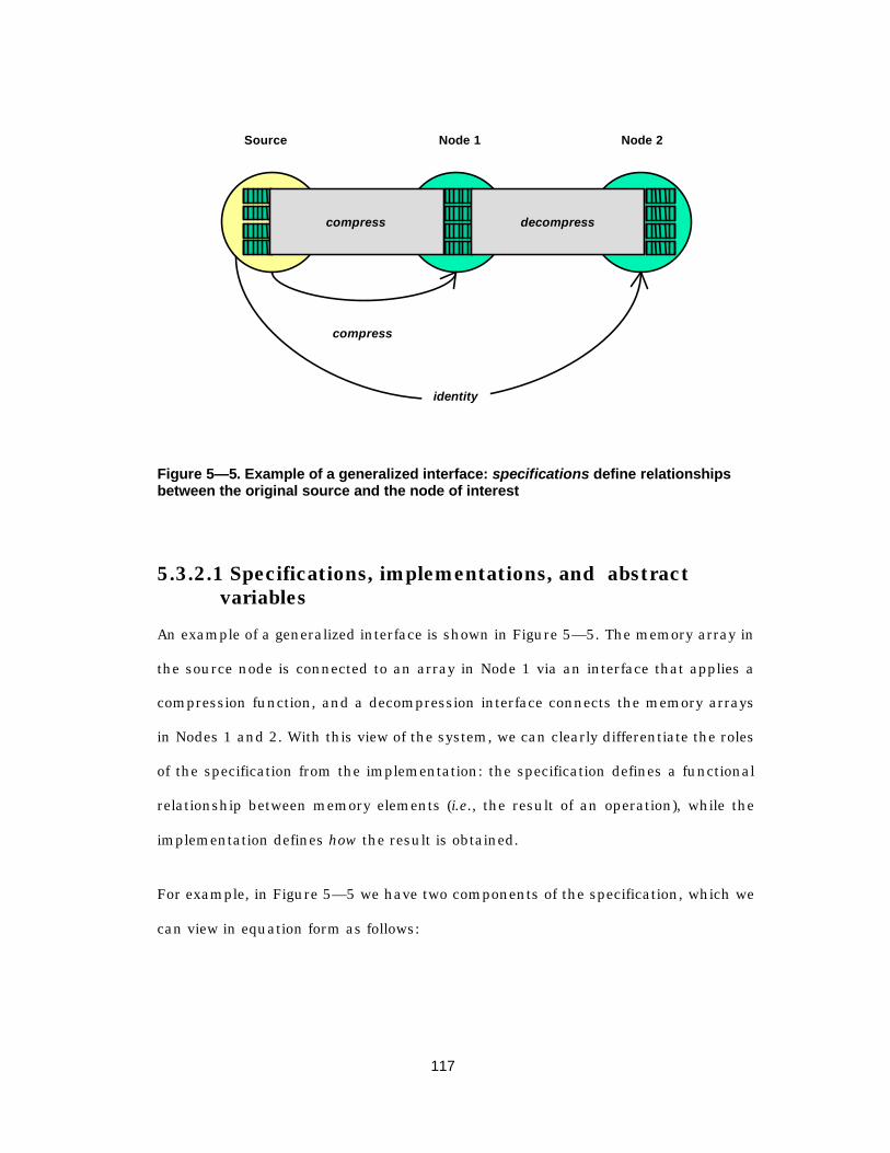
117
Source Node 2
decompress
Node 1
compress
compress
identity
Figure 5— 5. Example of a generalized interface: specifications define relationshipsbetween the original source and the node of interest
5.3.2.1 Specifications, implementations, and abstractvariables
An example of a generalized interface is shown in Figure 5— 5. The memory array in
the source node is connected to an array in Node 1 via an interface that applies a
compression function, and a decompression interface connects the memory arrays
in Nodes 1 and 2. With this view of the system, we can clearly differentiate the roles
of the specification from the implementation: the specification defines a functional
relationship between memory elements (i.e., the result of an operation), while the
implementation defines how the result is obtained.
For example, in Figure 5— 5 we have two components of the specification, which we
can view in equation form as follows:

118
Mem k Compress Mem k
Mem k Mem k1 0
2 0
==
( )
which requires the contents of a memory element in the Node 1 to be a compressed
version of the contents in the sender, and requires the contents in the destination
node (Node 2) to be identically equal to the contents in the source node.
Structuring the specification using functional relationships between memory
elements allows us to clearly identify the verification tasks. In this example, we are
obligated to prove that the implementation of the interface between the source and
Node 1 implements the specified compress function, and we must prove that the
concatenation of the two interfaces is equivalent to the identity function (i.e., pure
transfer). Compositional verification allows us to assume the result of the first
verification in proving the second verification, as follows:
assume
Mem k Compress Mem k
Decompress Compress x xprove
Mem k Decompress Mem k
1 0
2 1
==
=
( )
( ( ))
( )
Using the compositional inference rule of Theorem 1, we can safely infer that the
concatenation of the two interface functions implements the identity function.
Abstract variables
Before continuing, it is worthwhile to explain the role of abstract variables (also
called history variables) in the specification and verification process. The
generalized interface assumes the existence of memory arrays in each node in the
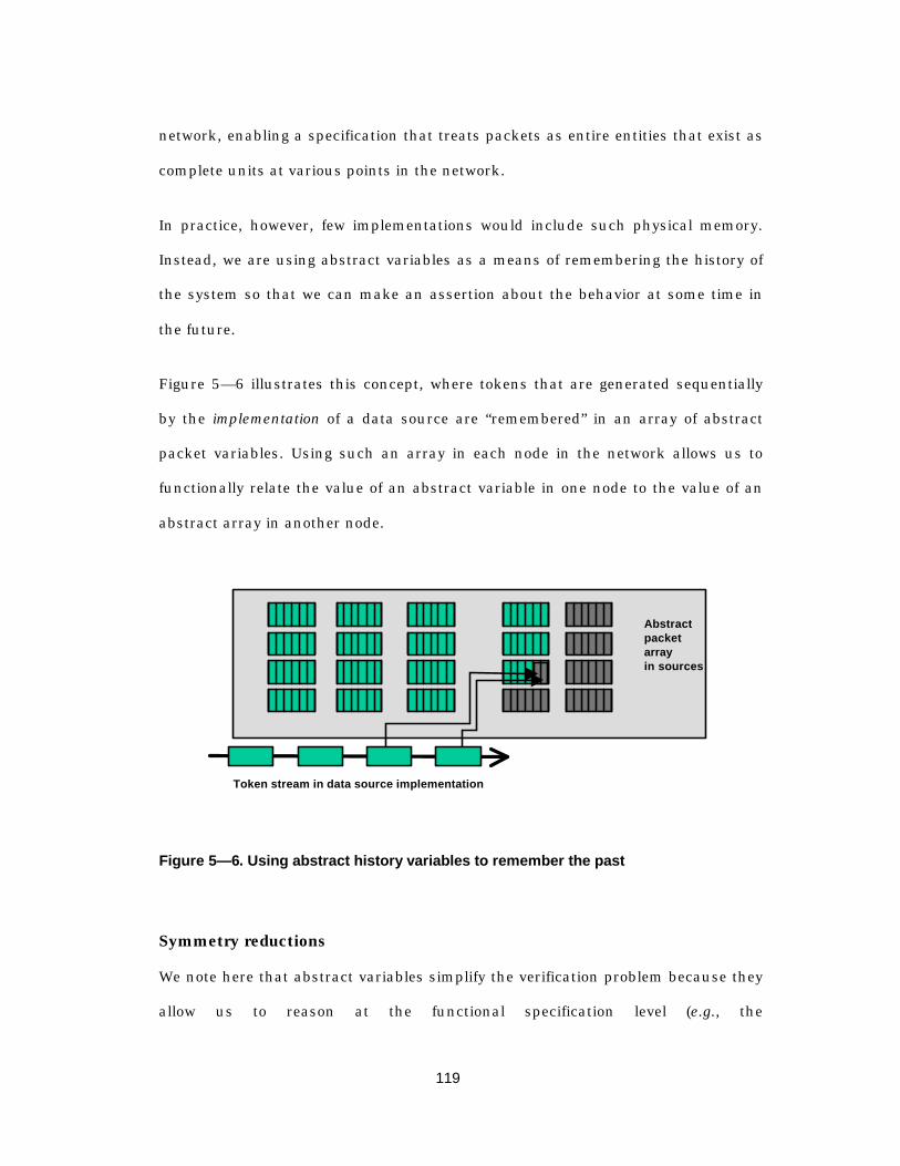
119
network, enabling a specification that treats packets as entire entities that exist as
complete units at various points in the network.
In practice, however, few implementations would include such physical memory.
Instead, we are using abstract variables as a means of remembering the history of
the system so that we can make an assertion about the behavior at some time in
the future.
Figure 5— 6 illustrates this concept, where tokens that are generated sequentially
by the implementation of a data source are “remembered” in an array of abstract
packet variables. Using such an array in each node in the network allows us to
functionally relate the value of an abstract variable in one node to the value of an
abstract array in another node.
Token stream in data source implementation
Abstractpacketarrayin sources
Figure 5— 6. Using abstract history variables to remember the past
Symmetry reductions
We note here that abstract variables simplify the verification problem because they
allow us to reason at the functional specification level (e.g., the

120
compress/decompress example of Figure 5— 5). At a first glance, it would appear
that we have increased the state space by using these abstract arrays. However, the
symmetry reduction techniques outlined in the previous chapter are especially well-
suited to arrays of symmetric objects, and when combined with compositional
verification we find that the verification problem falls apart if the refinement maps
are constructed appropriately.
One of the primary contributions of the refinement strategy presented in the
remainder of the chapter is the decomposition of the verification problem in such a
way that, for the class of data transfer networks under consideration, the
verification becomes essentially independent of the size of the system. The key
insight is that by separating the problem of “correctness” into a completeness
property, a data integrity property, and an ordering property, we can make
extensive use of symmetry.
The completeness problem can be expressed as a constraint on the tags in a packet
at the destination node. Given an “abstract variable” copy at the source node, the
completeness property asserts that all token tags in the output packet must appear
in the source packet, and vice-versa. Since the assertion is over the entire set of
tags in a given packet, ordering is unimportant, and thus the tags become
symmetric with respect to permutation. As will be discussed in Section 5.4, this
allows SMV to choose a representative set of two tokens and prove that the
property holds for an equivalent system in which there are only two tokens; by
symmetry the result extends to the full system.
The data integrity property asserts that the token values in the output packet must
match those in the source’s copy of the packet. Here, the token tags are used to
identify a particular token, but once again the order in which tokens are
121
transferred or compared is irrelevant to the outcome of the integrity property. Thus,
in proving the integrity property, SMV is once again able to use symmetry under
permutation to chose a representative token1 for which the integrity property is
checked.
Finally, the ordering problem addresses the fact that, in reality, ordering does
matter and tokens are not symmetric. When combined with a refinement in which
token transfers occur sequentially, the run-time of the verification problem
becomes essentially linear in the number of tokens in a packet. (We will investigate
this further in Section 5.4.4).
5.3.2.2 The role of refinement maps and witness functions
At the highest level of abstraction, we say that packets exist only in their entirety
and at discrete instants they may move from one point in the system to another.
Thus, in our example, the high-level abstraction requires that packets exist either
in the sender, the switch, or the receiver. Eventually, we map this onto an
implementation in which it is entirely possible that the packet does not exist as a
discrete entity at any point, but instead is simply a sequence of tokens that are
generated in a particular order. The purpose of the refinement maps in the following
discussion is to relate the low-level, detailed-timing behavior to a particular instant
where, from the high-level view, transfers occur atomically.
Temporally, we move to slightly lower-level view in which we allow a packet to exist
in three states: unsent, partially sent or completely sent, an abstraction that will be
1 Actually, if the SMV specification is structured correctly, the bits within each token are alsosymmetric, allowing the verification environment to be collapsed to a single bit-slice of the
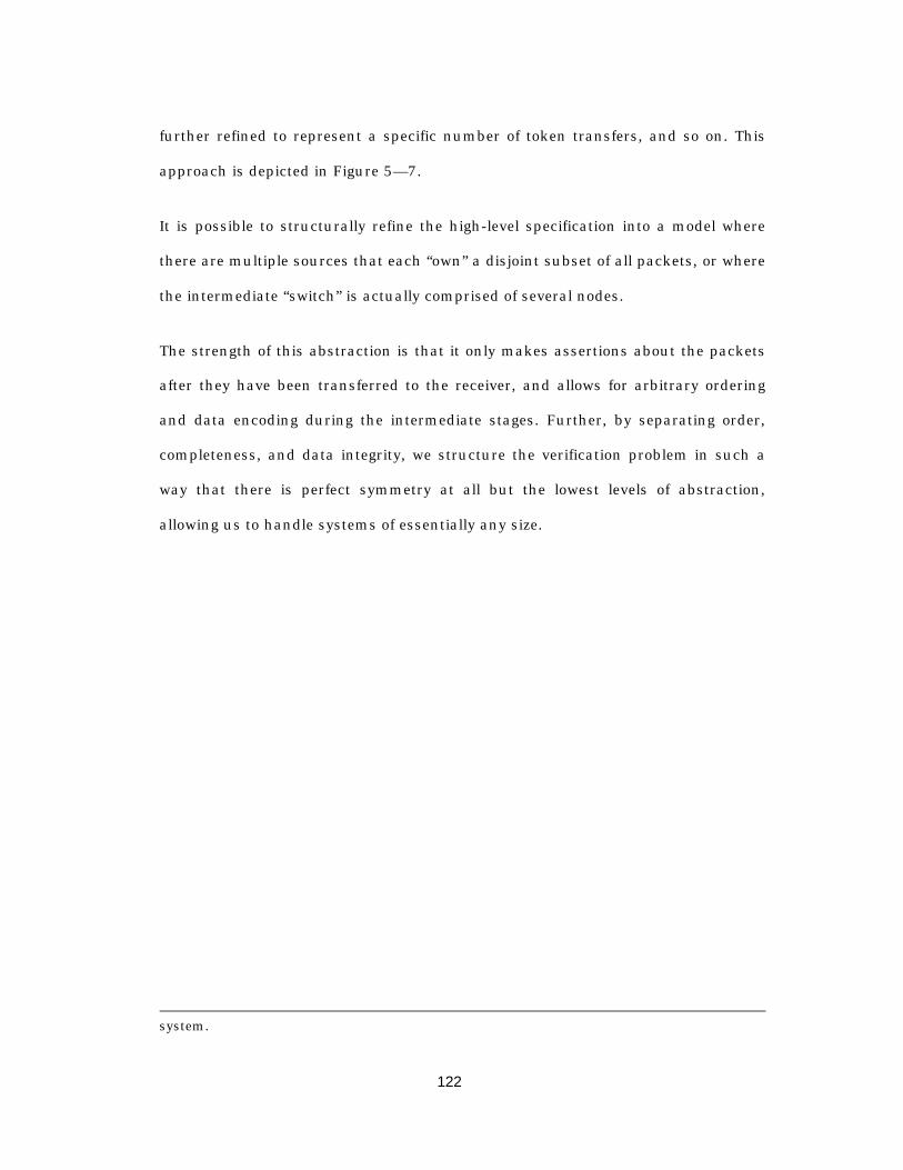
122
further refined to represent a specific number of token transfers, and so on. This
approach is depicted in Figure 5— 7.
It is possible to structurally refine the high-level specification into a model where
there are multiple sources that each “own” a disjoint subset of all packets, or where
the intermediate “switch” is actually comprised of several nodes.
The strength of this abstraction is that it only makes assertions about the packets
after they have been transferred to the receiver, and allows for arbitrary ordering
and data encoding during the intermediate stages. Further, by separating order,
completeness, and data integrity, we structure the verification problem in such a
way that there is perfect symmetry at all but the lowest levels of abstraction,
allowing us to handle systems of essentially any size.
system.
123
atomicp a c k e t
t r a n s fers
u n s e n tp a c k e t part ial ly
s e n t comp le te
token #1s e n t
t oken #2s e n t
t o k e n # Ns e n t
Figure 5— 7. Refinement hierarcy
The driving example that is used to demonstrate the technique is the packet
multiplexing chip in the InfoPad (see Section 0). Several data sources share a
common bus that is used to send packets – one word at a time – to the packet mux.
The task at hand is to show that the behavior of the implementation is functionally
equivalent to an SDL-level specification in which packets arrive atomically, are non-
deterministically delayed, and are sent on to the RF subsystem. We begin with a
brief introduction to the support mechanism for refinement verification in the SMV
system. The following section summarizes the major features of SMV relevant to
this refinement checking approach; an in-depth treatment can be found in
[McM93,McM97,McM98].

124
5.4 Refinement Verification in SMV
Recalling the discussion in Section 4.2.4, the compositional rule allowed us to use
induction over time by breaking zero-delay loops in the circuit. Further, in each
process pi we could constrain any signal as long as there was a well-founded order
→ between assignments.
In the SMV language the implementation of such a compositional rule defines a
“process” to be an assignment to a signal. Since the SMV language (as opposed to
the SMV model checking system) is a synchronous language, the advancement of
time is implicit. Assignments are made either to gates or latches; for gates we write
signal := expression;
and for a latch,
init(signal) := expression1;next(signal) := expression2;
Here, init(x) is the initial value of the signal, and next(x) is the value of the
signal at time t + 1 .
5.4.1 Layers
A design can be broken into layers, with the restriction that a given signal may be
assigned only once in any layer. Hence, an assignment (or process) can be uniquely
identified by a signal-layer pair, written as signal//layer. Since the core of the
SMV model checker deals with temporal logic assertions, each process is translated
into a temporal assertion about the behavior of the signal of interest.
125
The verification technique consists of defining the environment signals and using
them to prove that the model (i.e., collection of temporal assertions) of particular
signal in one layer implies a model of that signal in a higher layer. That is, the
behavior of a signal in a lower layer must be contained by behavior defined in a
higher layer. Syntactically, we write
usingsignal1//layer1,signal2//layer2,…
provesignalX//layerX;
to indicate that {signal1//layer1,signal2//layer2,…} should imply
{signalX//layerX}. In doing so, we take the conjunction of all of the environment
signals {signal1//layer1,signal2//layer2,…} and attempt to show that this
conjunction implies the specification {signalX//layerX}.
Two default layers, undefined and free, provide a flexible mechanism for proving
robustness as well as simplifying the job of the model checker. Assigning an
environment signal q to the undefined layer implies that the signal of interest p
should in no way depend on q 1. Assigning q to the free layer, on the other hand, is
used to indicate that the correct behavior of p should not depend on the particular
value of q – as long as q is well-defined. Signals assigned to these layers require no
space in the BDD used to represent the transition relationship.
1 The system is monotonic with respect to undefined values: logical operation can only tendtowards being more undefined.
126
5.4.2 Refinement
The refinement process is one of establishing a well-founded order between all
processes. Most of the time, the order → can be inferred from signal dependencies:
SMV assumes that an assumption about signal σ1 should be used to prove an
assertion about σ2 only when there is some actual zero-delay dependency from σ1
to σ2 . However, ambiguity arises if there is a zero delay path from σ2 toσ1 or if
there are multiple assignments to the same signal. To clarify these cases, the user
specifies the → order explicitly:
<implementation> refines <specification>;
indicating that the assignments in the lower layer (“implementation”) should be
contained by assignments in the higher level (“the specification”).
The power of this abstraction and refinement technique is twofold. The first lies in
the fact that, starting from the specification, we can break the verification problem
into localized steps that prove that an implementation is consistent with the
specification. These localized refinements usually require only a small fraction of
the entire system, and can be handled by an automated model checker. This is
illustrated in Figure 5— 8 in the refinement relationship between specificationB
and implementationB.
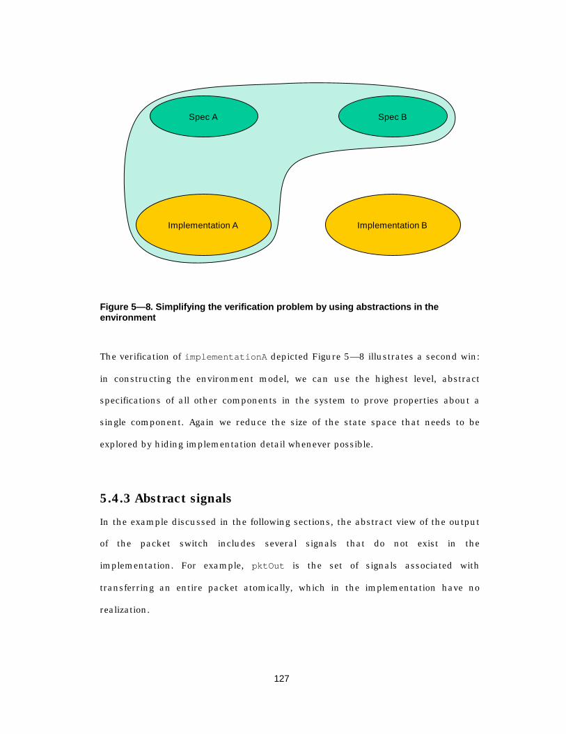
127
Spec A
Implementation A
Spec B
Implementation B
Figure 5— 8. Simplifying the verification problem by using abstractions in theenvironment
The verification of implementationA depicted Figure 5— 8 illustrates a second win:
in constructing the environment model, we can use the highest level, abstract
specifications of all other components in the system to prove properties about a
single component. Again we reduce the size of the state space that needs to be
explored by hiding implementation detail whenever possible.
5.4.3 Abstract signals
In the example discussed in the following sections, the abstract view of the output
of the packet switch includes several signals that do not exist in the
implementation. For example, pktOut is the set of signals associated with
transferring an entire packet atomically, which in the implementation have no
realization.
128
SMV provides the capability to define abstract signals that will not actually be
implemented, but that assist in the verification process. Referring to an abstract
signal from the implementation layer is not allowed.
5.4.4 Symmetry reduction techniques
The final concept needed in the groundwork for our verification technique is the
result of the application of symmetry reduction techniques (see Section 4.2.3). SMV
borrows the concept of scalarset types from the language Murφ[ID96].
5.4.4.1 Restrictions on Scalarsets
Scalarsets are finite types that have restrictions on the way in which they can be
used in order to guarantee that a program is semantically equivalent under any
permutation of the elements of the scalarset. Syntactically, we write
scalarset SENDER_TAG 0..(N – 1);
to create a scalarset whose elements take values in range 0 to N − 1 . However,
explicitly referring to a particular element of a scalarset is disallowed. Instead, only
certain constructs that are symmetric with respect to all elements in the scalarset
are allowed. These are:
1) Testing equality between two scalarset expressions of the same type
2) Arrays that are indexed by scalarsets
3) In a forall statement of the form
forall (i in <scalarset>) { <statements> }

129
4) Any commutative/associative operator may be applied as a “reduction operator”
over a scalarset type. For example, we can take the conjunction of the elements
of z as follows:
&[ z[i] : i in <scalarset>]
5) “Comprehension expressions” of the form {i : i in <scalarset>, z[i]} ,
which denotes the set of values i in the scalarset such that z[i] is true.
5.4.4.2 Dealing with asymmetry
The power of symmetry is that it allows the verification task to be reduced down to
a few cases, and the proof result is extended via symmetry. However, in the final
implementation layers this symmetry assumption no longer holds.
For example, we break the packet switch problem into 3 parts: token integrity,
packet completeness, and token ordering. For the first two of these, the tokens in a
packet are entirely symmetric, which allows us to write expressions of the form
forall(s in SENDERS)forall(p in PACKETS)
forall (t in TOKENS) {using
<environment>prove
<token integrity (s,p,t)>,<packet completeness (s,p) >
}
The above proof then reduces to only two verification problems that are shown for a
single token of a single packet of a single sender. Thus we can ignore all other
senders, packets, and tokens, so that the size of the model used to verify the
property is essentially independent of the size of the system.

130
However, at some point on the path to implementation the symmetry argument no
longer applies. For example, in showing that end-to-end ordering is preserved, the
tokens are no longer symmetric because we place an asymmetric order on them.
Hence we must break the symmetry assumption to show that a particular
implementation order is consistent with an arbitrary order defined in the
specification. The proof in this case is of the form:
breaking(TOKENS) {using
<environment>,<transfer in particular order>
prove<transfer in arbitrary order>
}
However, this verification problem is very localized and for practical packet sizes is
essentially linear in the number of words in the packet.
5.5 SDL Specification of a Packet Multiplexing sy stem
The basic architecture of the system we are considering is shown in Figure 5— 9.
This system consists of N senders that feed packets into a switching system that
stores the packets and, under the supervision of an external scheduling agent,
produces them at the output of the mux at some time in the future. Additionally, a
packet may be discarded if there is no available storage space, or if the scheduling
agent instructs the switch to eliminate a packet from its buffers. Reasoning in the
abstract, we can say that the switch accepts packets, delays them for a non-
deterministic period of time (perhaps forever, since the scheduler can cause the
switch to discard a packet), and produces them at the output. Our goal is to show
that whatever appears at the output corresponds to the data sent by one of the
senders.

131
Source 0
Source 1
Source N-1
PacketMux
Scheduler
Destination
Figure 5— 9. Packet Mux System
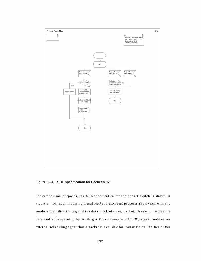
132
Process PacketMux 1(1)
dcl chanbufs ChannelBufferArray, bufID PACKET_TAG, pktID PACKET_TAG, srcID SOURCE_TAG;
Idle
Packet(srcID,dataIn)
ReleasePacket(srcID,pktID)
DiscardPacket(srcID,pktID)
bufferAvailablePacketOut(chanbufs(srcID,pktID))via RF_INTERFACE
'discard packet''set bufID :=
a free buffer inchanbufs(srcID)'
'return bufID tothe free store'
chanbufs(srcID,bufID) := dataIn Idle
PacketReady(srcID)to Scheduler
Idle
falsetrue
Figure 5— 10. SDL Specification for Packet Mux
For comparison purposes, the SDL specification for the packet switch is shown in
Figure 5— 10. Each incoming signal Packet(srcID,data) presents the switch with the
sender’s identification tag and the data block of a new packet. The switch stores the
data and subsequently, by sending a PacketReady(srcID,bufID) signal, notifies an
external scheduling agent that a packet is available for transmission. If a free buffer
133
is not available for the incoming packet, it is dropped. At some time in the future,
the external scheduler may release a packet for transmission on the output link (by
sending a ReleasePkt(srcID,bufID) signal), or it may notify the switch to discard the
packet.
5.6 Sequential implementation of the switch
The SDL view of the switch presents the abstractions that packets arrive
atomically. However, in a realistic implementation, the packets would be spread out
over time, arriving sequentially word-by-word.
One such implementation is the TX subsystem in the InfoPad (see Chapter 2). In
the InfoPad, the data sources are the audio, pen, keyboard, and microprocessor
subsystems, and these sources transfer packets to the TX subsystem a single byte
at a time via the IPBus. Since all data sources may simultaneously be in the
process of transferring a packet, the TX subsystem must maintain a separate
queue for each possible data source. The basic data transfer protocol begins with a
special Start of Packet (SOP) tag, followed by some number of data bytes, and
terminates the transfer with an End of Packet (EOP) tag.
The motivation for using this example is the highly parallel/pipelined nature of the
operation. In principle, each sender can have a packet in progress, and our
experience with the actual implementation was that it was difficult to keep track of
the various pointers, counters, and buffers associated with each sender. Subtle
design errors that escaped simulation were required several iterations of the
implementation before they were corrected. Before McMillan’s recent additions to

134
SMV, formally verifying that the implementation preserved the order and integrity
of the data was an intractable problem.
Before continuing, it is worth noting that a key to relating the sequential
implementation to an SDL abstraction in which transfers happen atomically is the
fact that in the sequential version only a single packet can complete its transfer in
a given clock cycle. Thus in the synchronous version we can faithfully replicate the
SDL abstraction that only a single event is drawn from the input queue during a
transition. While this is not crucial to the overall abstraction/refinement approach
discussed earlier, the relationship between the SDL specification and the SMV
model is worth mentioning.
5.7 Outline of the proof
The decomposition of the system into layers that progress from the abstraction to
the implementation is shown in Figure 5— 11. The system is separated into
senders, a receiver, a set of miscellaneous “environment” functions (not shown),
and the packet switch itself. At the highest-level of abstraction, each sender non-
deterministically chooses to request a transfer, and from the requesting senders the
environment non-deterministically chooses a single sender, and the transfer takes
place atomically after a non-deterministic delay (which may be zero).
Independently, an external scheduler non-deterministically chooses from among
the buffers that the mux offers for transmission. When the receiver indicates that it
is ready, the mux transfers the packet atomically after a non-deterministic delay
(again, which may be zero).

135
atomicSend input_spec output_spec recv_spec
seqStore seqFetch
orderedFetch
recv_seq
recv_ordered
seqSend
Switch
Implementation
Specification
Refinement Maps
recv_via_switch
Figure 5— 11. Organization of Layers
This functional independence between transfers into and out of the switch provides
a natural point at which the proof can be broken into independent steps. We make
use of compositional verification in our proof by dividing the desired properties into
a set of constraints on the input to and the output from the local storage (i.e.,
packet buffers) in the switch. We first show that we can get data into these packet
buffers correctly, ignoring the output of the switch. Next we assume that data in
the packet buffers is correct, and then show that we can get it out of the buffers
without corrupting it. This sort of reasoning is an example of the induction over
time mentioned earlier: we assume that the contents of the local store is correct up
to the last instant, and prove our properties from the current instant forward.
Our proof has three main objectives: proving integrity, completeness, and ordering.
The data integrity proof is done at the highest level of abstraction, where packet
transfers are atomic. At this level, ordering is irrelevant and completeness is an
assertion: the entire packet is either transferred or it is not. As we refine to a
136
sequential view of the system, we must show that the sequential transfer (a)
maintains the data integrity, (b) transfers entire packets, and eventually (c) tokens
appearing at the output of the mux do so in a particular order.
5.8 SMV Specification
In the following sections, we explain the major features of each layer. Our goal is to
use this detailed example to present a feel for the approach to abstraction and for
the proof technique. From the outset, we should point out that there are many
possible abstractions for a given implementation – how one chooses to abstract a
design depends upon the properties that are to be proved. In general, it is
necessary to strike a balance between generality and timeliness. One would usually
like to minimize the number of proof obligations, which implies fewer layers with
more detail in each layer, while keeping the problem within the grasp of the model
checker. We will point out these tradeoffs in the following sections.
5.8.1 Specifying data integrity at the atomic transfer level
5.8.1.1 The atomicSend layer
We start with the high-level specification of a data source. Each source maintains a
collection of packets, each having a fixed number of tokens, where each token has
a fixed number of bits that are initialized with random values. We write this as

137
layer atomicSend: {
forall(pkt in PACKET_TAG)forall(t in TOKEN_TAG)
forall(bit in BIT_TAG) { packets[pkt].pkt_tag := pkt;
init(packets[pkt].data[t].value[bit]) :={true,false};
next(packets[pkt].data[t].value[bit]) :=packets[pkt].data[t].value[bit];
}…
}
Each sender is either in the idle state or the in_progress state. The basic
transfer protocol is as follows. When in the idle state, the sender non-
deterministically chooses to issue a request to the environment. If during the next
cycle the environment fails to respond with a grant, then the sender non-
deterministically chooses whether to continue to assert its request signal and the
process is repeated.
If, however, the environment responds with a grant, then a transfer is initiated
(startPkt is asserted), and the sender non-deterministically chooses whether to
delay the transfer or to complete it on this cycle. If it chooses to delay the
completion, the sender moves to the in_progress state, and at some (non-
deterministic) time in the future, the sender will choose to complete the packet by
asserting its endPkt signal. This behavior is specified as part of the atomicSend
layer, which is continued below:
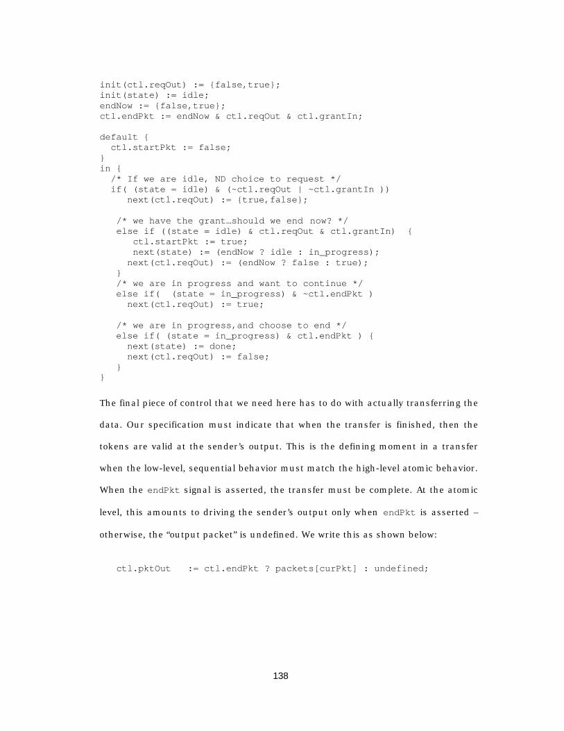
138
init(ctl.reqOut) := {false,true};init(state) := idle;endNow := {false,true};ctl.endPkt := endNow & ctl.reqOut & ctl.grantIn;
default { ctl.startPkt := false;}in { /* If we are idle, ND choice to request */ if( (state = idle) & (~ctl.reqOut | ~ctl.grantIn )) next(ctl.reqOut) := {true,false};
/* we have the grant…should we end now? */else if ((state = idle) & ctl.reqOut & ctl.grantIn) {
ctl.startPkt := true;next(state) := (endNow ? idle : in_progress);
next(ctl.reqOut) := (endNow ? false : true); }
/* we are in progress and want to continue */ else if( (state = in_progress) & ~ctl.endPkt ) next(ctl.reqOut) := true;
/* we are in progress,and choose to end */ else if( (state = in_progress) & ctl.endPkt ) { next(state) := done; next(ctl.reqOut) := false; }}
The final piece of control that we need here has to do with actually transferring the
data. Our specification must indicate that when the transfer is finished, then the
tokens are valid at the sender’s output. This is the defining moment in a transfer
when the low-level, sequential behavior must match the high-level atomic behavior.
When the endPkt signal is asserted, the transfer must be complete. At the atomic
level, this amounts to driving the sender’s output only when endPkt is asserted –
otherwise, the “output packet” is undefined. We write this as shown below:
ctl.pktOut := ctl.endPkt ? packets[curPkt] : undefined;

139
5.8.1.2 The input_spec layer
We shift our attention to the packet switch at this point. Overall, the job of the
switch is to store packets and later forward them. Thus our specification must
include some type of memory management, and a relationship between the
contents of memory and the packets in a sender module.
The most general memory management scheme is one in which the switch
maintains a pool of free buffers, and incoming packets are assigned arbitrarily to
any one of the free buffers. However, for our purposes we divide the buffers into
groups, where each sender module has its own dedicated group (called a channel).
(The motivation for doing this was based upon the fact that implementation is
structured into channels, and because the memory allocation scheme was not the
primary interest in the example. By starting with the general allocation scheme, we
would need to prove that the channel-reservation scheme implied the general
scheme. The current approach avoids this proof step at the expense of generality.)
The memory management specification is shown below:
layer input_spec: { forall(s in SENDER_TAG) forall(b in BUFFER_TAG) { next(localStore[s].bufstate[b]) := switch(localStore[s].bufstate[b]){
avail : {avail,used,ready}; used : localStore[s].reset[b] ?
avail : {used,ready}; ready : localStore[s].reset[b] ?
avail : ready; };
Buffers in the memory pool are in one of three states: available, used, or ready.
If a packet is ready, it has been received in its entirety by the switch and is eligible
for forwarding; used packets have been allocated but have tokens that have not
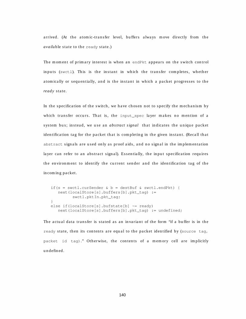
140
arrived. (At the atomic-transfer level, buffers always move directly from the
available state to the ready state.)
The moment of primary interest is when an endPkt appears on the switch control
inputs (swctl). This is the instant in which the transfer completes, whether
atomically or sequentially, and is the instant in which a packet progresses to the
ready state.
In the specification of the switch, we have chosen not to specify the mechanism by
which transfer occurs. That is, the input_spec layer makes no mention of a
system bus; instead, we use an abstract signal that indicates the unique packet
identification tag for the packet that is completing in the given instant. (Recall that
abstract signals are used only as proof aids, and no signal in the implementation
layer can refer to an abstract signal). Essentially, the input specification requires
the environment to identify the current sender and the identification tag of the
incoming packet.
if(s = swctl.curSender & b = destBuf & swctl.endPkt) {next(localStore[s].buffers[b].pkt_tag) :=
swctl.pktIn.pkt_tag; }
else if(localStore[s].bufstate[b] ~= ready)next(localStore[s].buffers[b].pkt_tag) := undefined;
The actual data transfer is stated as an invariant of the form “if a buffer is in the
ready state, then its contents are equal to the packet identified by (source tag,
packet id tag).” Otherwise, the contents of a memory cell are implicitly
undefined.
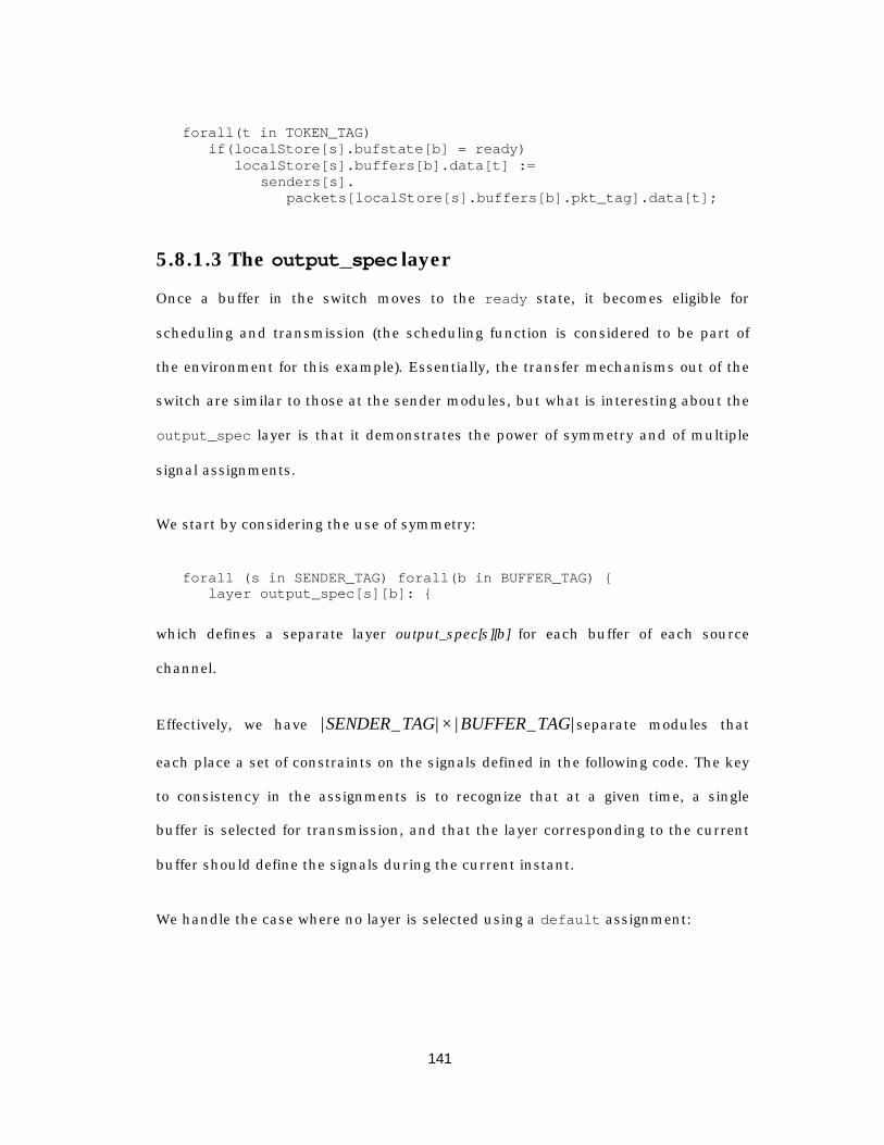
141
forall(t in TOKEN_TAG) if(localStore[s].bufstate[b] = ready)
localStore[s].buffers[b].data[t] :=senders[s].
packets[localStore[s].buffers[b].pkt_tag].data[t];
5.8.1.3 The output_spec layer
Once a buffer in the switch moves to the ready state, it becomes eligible for
scheduling and transmission (the scheduling function is considered to be part of
the environment for this example). Essentially, the transfer mechanisms out of the
switch are similar to those at the sender modules, but what is interesting about the
output_spec layer is that it demonstrates the power of symmetry and of multiple
signal assignments.
We start by considering the use of symmetry:
forall (s in SENDER_TAG) forall(b in BUFFER_TAG) {layer output_spec[s][b]: {
which defines a separate layer output_spec[s][b] for each buffer of each source
channel.
Effectively, we have | _ | | _ |SENDER TAG BUFFER TAG× separate modules that
each place a set of constraints on the signals defined in the following code. The key
to consistency in the assignments is to recognize that at a given time, a single
buffer is selected for transmission, and that the layer corresponding to the current
buffer should define the signals during the current instant.
We handle the case where no layer is selected using a default assignment:
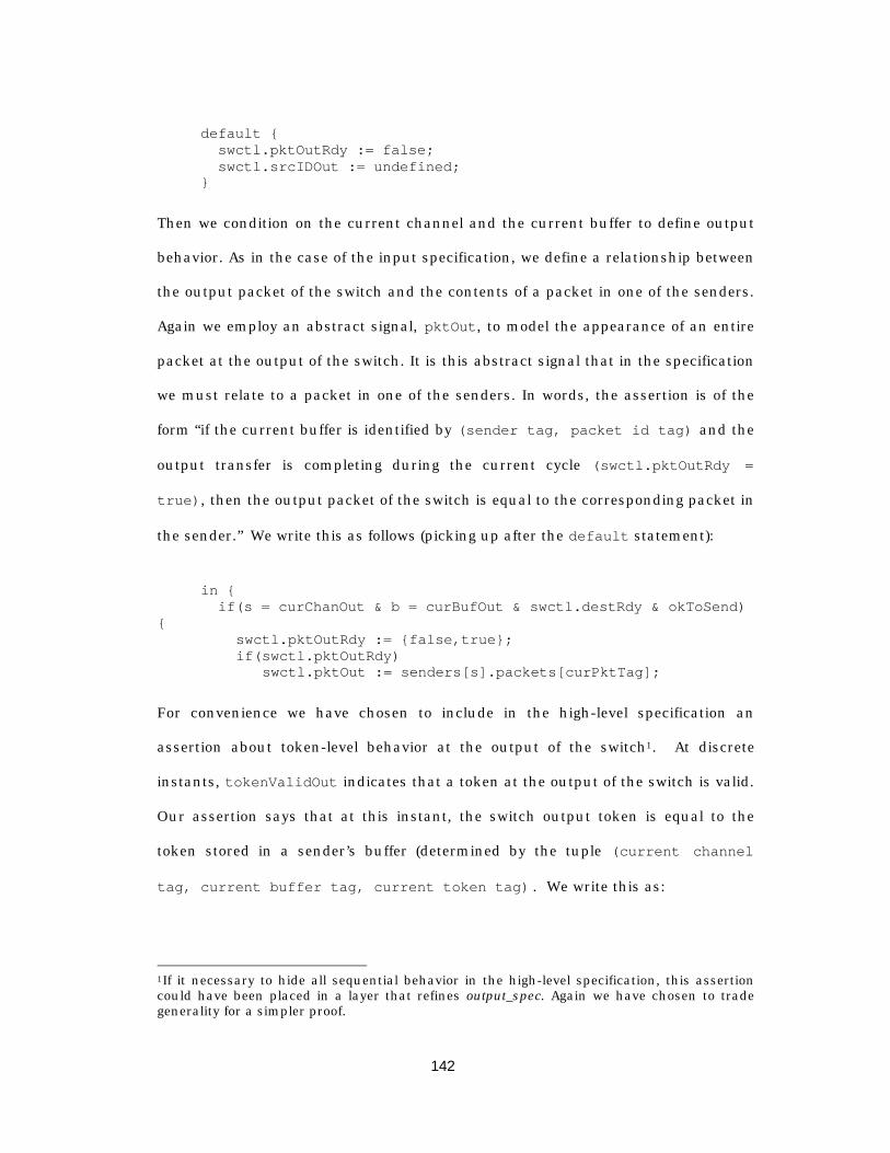
142
default { swctl.pktOutRdy := false; swctl.srcIDOut := undefined; }
Then we condition on the current channel and the current buffer to define output
behavior. As in the case of the input specification, we define a relationship between
the output packet of the switch and the contents of a packet in one of the senders.
Again we employ an abstract signal, pktOut, to model the appearance of an entire
packet at the output of the switch. It is this abstract signal that in the specification
we must relate to a packet in one of the senders. In words, the assertion is of the
form “if the current buffer is identified by (sender tag, packet id tag) and the
output transfer is completing during the current cycle (swctl.pktOutRdy =
true), then the output packet of the switch is equal to the corresponding packet in
the sender.” We write this as follows (picking up after the default statement):
in { if(s = curChanOut & b = curBufOut & swctl.destRdy & okToSend){ swctl.pktOutRdy := {false,true};
if(swctl.pktOutRdy) swctl.pktOut := senders[s].packets[curPktTag];
For convenience we have chosen to include in the high-level specification an
assertion about token-level behavior at the output of the switch1. At discrete
instants, tokenValidOut indicates that a token at the output of the switch is valid.
Our assertion says that at this instant, the switch output token is equal to the
token stored in a sender’s buffer (determined by the tuple (current channel
tag, current buffer tag, current token tag) . We write this as:
1If it necessary to hide all sequential behavior in the high-level specification, this assertioncould have been placed in a layer that refines output_spec. Again we have chosen to tradegenerality for a simpler proof.
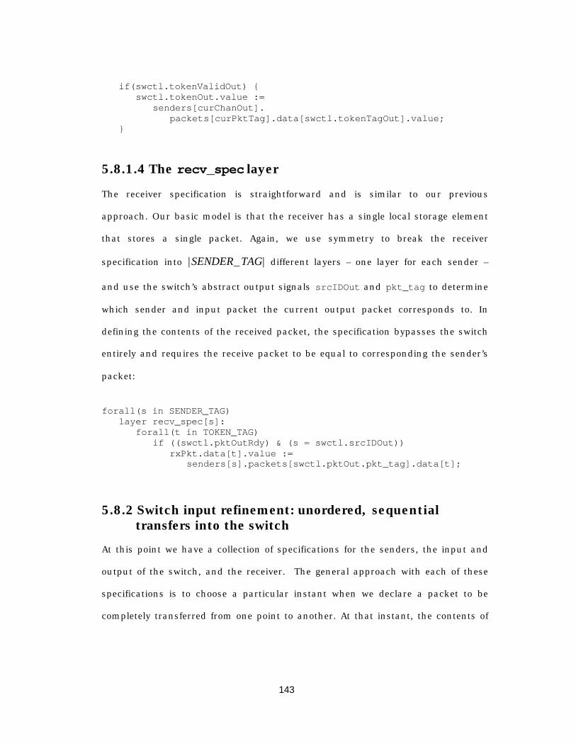
143
if(swctl.tokenValidOut) { swctl.tokenOut.value :=
senders[curChanOut].packets[curPktTag].data[swctl.tokenTagOut].value;
}
5.8.1.4 The recv_spec layer
The receiver specification is straightforward and is similar to our previous
approach. Our basic model is that the receiver has a single local storage element
that stores a single packet. Again, we use symmetry to break the receiver
specification into | _ |SENDER TAG different layers – one layer for each sender –
and use the switch’s abstract output signals srcIDOut and pkt_tag to determine
which sender and input packet the current output packet corresponds to. In
defining the contents of the received packet, the specification bypasses the switch
entirely and requires the receive packet to be equal to corresponding the sender’s
packet:
forall(s in SENDER_TAG)layer recv_spec[s]:
forall(t in TOKEN_TAG) if ((swctl.pktOutRdy) & (s = swctl.srcIDOut))
rxPkt.data[t].value :=senders[s].packets[swctl.pktOut.pkt_tag].data[t];
5.8.2 Switch input refinement: unordered, sequentialtransfers into the switch
At this point we have a collection of specifications for the senders, the input and
output of the switch, and the receiver. The general approach with each of these
specifications is to choose a particular instant when we declare a packet to be
completely transferred from one point to another. At that instant, the contents of
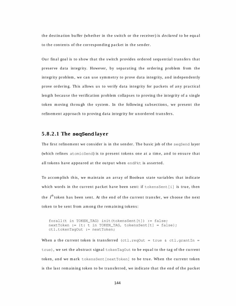
144
the destination buffer (whether in the switch or the receiver) is declared to be equal
to the contents of the corresponding packet in the sender.
Our final goal is to show that the switch provides ordered sequential transfers that
preserve data integrity. However, by separating the ordering problem from the
integrity problem, we can use symmetry to prove data integrity, and independently
prove ordering. This allows us to verify data integrity for packets of any practical
length because the verification problem collapses to proving the integrity of a single
token moving through the system. In the following subsections, we present the
refinement approach to proving data integrity for unordered transfers.
5.8.2.1 The seqSend layer
The first refinement we consider is in the sender. The basic job of the seqSend layer
(which refines atomicSend) is to present tokens one at a time, and to ensure that
all tokens have appeared at the output when endPkt is asserted.
To accomplish this, we maintain an array of Boolean state variables that indicate
which words in the current packet have been sent: if tokensSent[i] is true, then
the ith token has been sent. At the end of the current transfer, we choose the next
token to be sent from among the remaining tokens:
forall(t in TOKEN_TAG) init(tokensSent[t]) := false;nextToken := {t: t in TOKEN_TAG, tokensSent[t] = false};ctl.tokenTagOut := nextToken;
When a the current token is transferred (ctl.reqOut = true & ctl.grantIn =
true), we set the abstract signal tokenTagOut to be equal to the tag of the current
token, and we mark tokensSent[nextToken] to be true. When the current token
is the last remaining token to be transferred, we indicate that the end of the packet
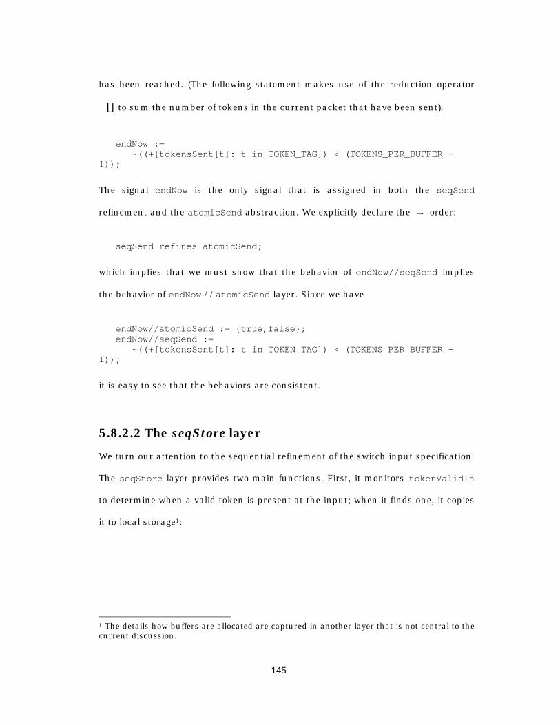
145
has been reached. (The following statement makes use of the reduction operator
+ [] to sum the number of tokens in the current packet that have been sent).
endNow :=~((+[tokensSent[t]: t in TOKEN_TAG]) < (TOKENS_PER_BUFFER -
1));
The signal endNow is the only signal that is assigned in both the seqSend
refinement and the atomicSend abstraction. We explicitly declare the → order:
seqSend refines atomicSend;
which implies that we must show that the behavior of endNow//seqSend implies
the behavior of endNow //atomicSend layer. Since we have
endNow//atomicSend := {true,false};endNow//seqSend :=
~((+[tokensSent[t]: t in TOKEN_TAG]) < (TOKENS_PER_BUFFER -1));
it is easy to see that the behaviors are consistent.
5.8.2.2 The seqStore layer
We turn our attention to the sequential refinement of the switch input specification.
The seqStore layer provides two main functions. First, it monitors tokenValidIn
to determine when a valid token is present at the input; when it finds one, it copies
it to local storage1:
1 The details how buffers are allocated are captured in another layer that is not central to thecurrent discussion.
146
layer seqStore: {s := swctl.curSender;t := senders[s].ctl.tokenTagOut;if(swctl.tokenValidIn)
next(localStore[s].buffers[destBuf].data[t]) := swctl.tokenIn;
Notice that in the above assignment, we are reading from the “system bus” input to
the switch to determine the value of the input token that we are placing into local
storage. In the specification, however, we defined the contents of the local storage
using a direct assignment from the sender’s store. Thus, if we are able to prove that
the contents of the local buffer is correct when the values are read sequentially
from the system bus, we have shown both that the sequential behavior is
consistent and that the system bus does not corrupt data.
The second task of this layer is to refine our view of how buffers in the free store
transition from the available state, to the used state, and finally to the ready state.
forall(s in SENDER_TAG) forall(b in BUFFER_TAG) { init(localStore[s].bufstate[b]) := avail; if(localStore[s].reset[b]) { next(localStore[s].bufstate[b]) := avail; } else { if(s = swctl.curSender & b = destBuf) {
if(swctl.startPkt) next(localStore[s].bufstate[b]) :=
swctl.endPkt ? ready : used;else if (swctl.endPkt)
next(localStore[s].bufstate[b]) := ready; } } }
The essence of the above code is that buffers move from the available state to the
used state when the current sender asserts the startPkt signal. The buffer
remains in this state until the same sender asserts endPkt, at which time the
buffer moves to the ready state. The point worth noting is that the way this
refinement is written, it assumes startPkt and endPkt are not simultaneously
147
asserted. In the specification of the sender it was entirely possible that both signals
are simultaneously asserted – this is the case in which the packet begins and
finishes in a single instant.
This difference in assumed behavior from between the specification and the
implementation illustrates the need to precisely identify the layers from which the
environment signals are drawn. In this case, to prove that the buffer state changes
according to the behavior specified in the input_spec layer, it is necessary to use
the implementation behavior of the sender.
5.8.2.3 Proving sequential transfers imply atomic transfers
At this point it is worthwhile to demonstrate the construction of a proof, and to
explain the various bag of tricks that one can use to fully exploit symmetry to
simplify the verification task. The overall goal of this section is to provide insight
about how one reasons about a system in order to simplify its verification.
The preceding section described the seqStore layer and its role in capturing
tokens at the input of the switch an storing them in local memory. Thus the
seqStore layer assigns data words to local memory using an assignment that is
equivalent to the following:
if(swctl.tokenValidIn) next(seqStore//localStore[s].buffers[destBuf].data[t]) :=
swctl.tokenIn;
However, the input specification also makes an assignment to the same local
storage by reading directly from the sender’s buffer. Recall from Section 5.8.1.2, we
had
148
forall(t in TOKEN_TAG) if(localStore[s].bufstate[b] = ready)
localStore[s].buffers[b].data[t] :=senders[s].packets[localStore[s].
buffers[b].pkt_tag].data[t];
Thus our proof obligation is to show that reading tokens out of our local store is
equivalent to simply reading them from the sender’s store. If this property holds,
then we are assured that at least we can transfer tokens into the switch without
corrupting them; proving that we can get them out of the switch is a separate
problem.
We start by recognizing the symmetry of senders, packets, and tokens. In the
description thus far, permuting the senders, the packets within a sender, the
tokens within a given packet, or the bits within a given token would change nothing
about the behavior of the system. Thus, we structure our proof in a similar fashion,
selecting an arbitrary word, of an arbitrary buffer, of an arbitrary sender:
forall(s in SENDER_TAG) forall(b in BUFFER_TAG) forall(t inTOKEN_TAG) {
using<environment specific to (s,b,t)>,localStore[s].buffers[b].data[t]//seqStore
provelocalStore[s].buffers[b].data[t]//input_spec
}
The SMV system recognizes the symmetry in the above proof obligation and
reduces its verification to the problem of proving the implication for the single-bit
packet
localStore[0].buffers[0].data[0].value[0].
Figure 5— 12 illustrates the construction of the verification environment for the
current proof. Since we seek to prove properties about the sequential behavior of
the input storage mechanism in the switch, we will need to rely on the sequential
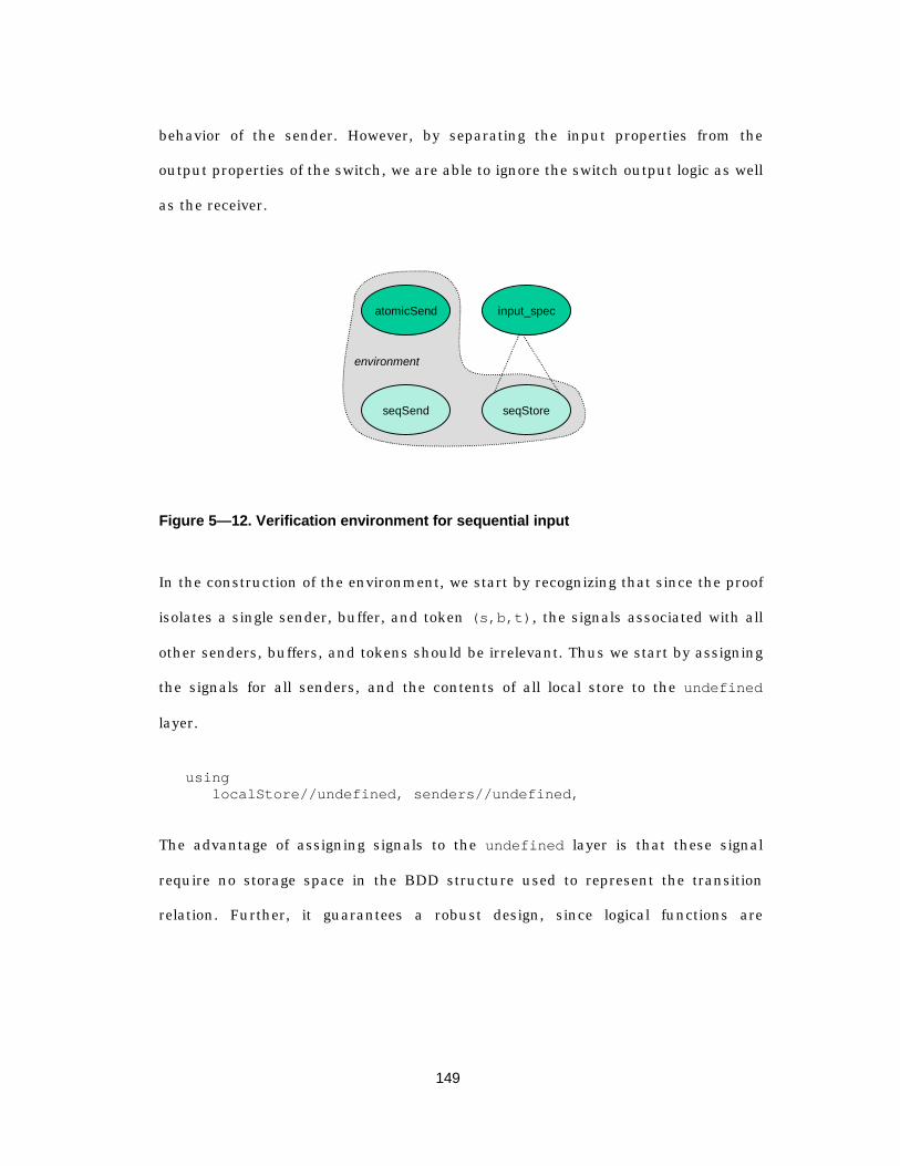
149
behavior of the sender. However, by separating the input properties from the
output properties of the switch, we are able to ignore the switch output logic as well
as the receiver.
atomicSend
seqSend
environment
seqStore
input_spec
Figure 5— 12. Verification environment for sequential input
In the construction of the environment, we start by recognizing that since the proof
isolates a single sender, buffer, and token (s,b,t), the signals associated with all
other senders, buffers, and tokens should be irrelevant. Thus we start by assigning
the signals for all senders, and the contents of all local store to the undefined
layer.
usinglocalStore//undefined, senders//undefined,
The advantage of assigning signals to the undefined layer is that these signal
require no storage space in the BDD structure used to represent the transition
relation. Further, it guarantees a robust design, since logical functions are
150
monotonic with respect to undefined signals (i.e., undefined values propagate
through the system). Hence, any unintended dependence can quickly be detected.1
Since SMV uses the most-defined layer available for a signal definition, we can
override the above assignment for the particular signals of interest. We start with
the local storage associated with the current token, local store buffer, and sender,
which in the sequel we denote by the 3-tuple (s,b,t).
localStore[s].reset[b]//free,localStore[s].bufstate[b]//input_spec,localStore[s].buffers[b].data[t]//seqStore,
The reasoning behind the above layer assignments is that the contents of the local
store associated with (s,b,t) is defined only when the buffer state is ready. That
is, if the buffer is in the ready state, then the data integrity property must hold.
Since we are not attempting to prove anything about when a transition between
ready and available is allowed, assigning the reset signal to the free layer
allows the buffer to return to the free store at any time. This enables us to ignore
all of the logic that drives the reset signal, reducing the number of variables in the
BDD.
Next, we add the signals from the current sender to the environment. The first
group of these deal mostly with the signaling protocol that indicates the boundaries
of packet transfers and can be drawn from the high-level atomic transfer
specification for the sender:
1 The only disadvantage to this approach is that, at least in the current implementation ofSMV, you must explicitly and individually define every signal in the layer of interest,resulting in rather verbose using… prove declarations.
151
senders[s].state//atomicSend,senders[s].ctl.endPkt//atomicSend,senders[s].ctl.pktOut//atomicSend,senders[s].ctl.reqOut//atomicSend,senders[s].ctl.grantIn//free,senders[s].ctl.startPkt//atomicSend,
In the sequential view of the sender, the only signal of interest is the one that
defines the instant when all of the words have been transferred – this is the endNow
signal. Since the value of this signal is a function of which words have been
transferred, we must also add to our environment the tokensSent array. However,
because at endNow depends only on the fact that we are sending the last token in a
packet we can assign tokensSent to the free layer:
senders[s].tokensSent//free,senders[s].endNow//seqSend,
Further, in verifying the integrity of data flowing through the switch, the particular
value of the data is inconsequential to the proof. Thus, we can further simplify by
assigning the contents of all packets in the current sender to the free layer:
senders[s].packets//free,
Finally, there are several signals that are used by the layers that choose the sender,
control access to the switch, and choose the destination buffer for incoming
packets.
swctl.endPkt//senderControl[s],swctl.startPkt//senderControl[s],destBuf//destChoice[s],curActiveBuf[s]//destChoice[s],curActive[s]//destChoice[s]
The resulting BDD has only 10 state variables and 17 combinational variables,
independent of the number of senders, buffers, tokens, or bits per token, and can
be verified by the model checker in less than 3 seconds on a standard workstation.

152
5.8.3 Switch output refinement
We pause for a moment to take stock of where we are. We started with a high-level
specification for source and switch where we used defined the value of local storage
in the switch directly in terms of packets in the senders’ store. At the instant in
which a transfer occurs, the sender identifies itself as well as the packet
identification tag, which are stored by the switch.
We then refined that view into one in which a system bus drives the input of the
switch and at precise moments the switch stores the value that is present on the
system bus. By verifying that this refinement implied the behavior of the abstract
specification (input_spec), we verified that getting data into the switch sequentially
did not alter the data.
input_spec
seqFetch
output_specsender[s].packet
Figure 5— 13. Verification environment for sequential output
Now we turn our attention to the output of the switch, and again we must show
that the integrity of the data is preserved. But here, the power of compositional
verification becomes apparent: in proving properties about the output of the switch,
we able to assume the correctness of the data in the local store, and thus can
153
ignore the problem of getting data into the switch. This is illustrated in Figure 5—
13, and will become apparent in the following proof steps.
5.8.3.1 The seqFetch layer
The output specification related the value of the switch output packet and tokens
to data that are directly read from the sender. In the first refinement of the output
specification, we sequentially read tokens from local storage and place them onto
the output of the switch. Our proof obligation is to show that what is read from the
local storage is equivalent to what is read directly from the sender. (A separate
proof step that includes the receiver is needed to show that sequentially emitting
tokens is equivalent to emitting an entire packet atomically. We will address that in
a later section).
Again we use the multiple-assignment capability and define a separate layer
seqFetch[s][b] for each sender and buffer. The function of seqFetch[s][b] is
to define (or “drive”) the output signal only when s is the ID of the sender that
generated the current output packet, and b is the index of the local storage buffer
that hold the packet. Conceptually, all | _ | | _ |SENDER TAG BUFFER TAG¥ layers
simultaneously monitor the currentChan and curBuf signals to determine if it
should drive the output of the switch. Since only one sender (curChan) and one
buffer (curBuf) can be active at a given time, we are guaranteed that only one layer
drives the logic. Since each of the resulting layers operates independently and deals
with a single buffer from a single sender, all layers seqFetch[s][b] are symmetric.
Again we have reduced the size of the verification task to something that is
essentially independent of the number of senders and buffers.
154
The other simplification we make here is in separating the problem of data integrity
from ordering. In the seqFetch layer, we maintain an array of boolean variables
that indicate which tokens we have sent. At the beginning of a packet, we initialize
tokensSent[j] to false, and on each subsequent token we choose from among
the tokens that remain to be sent, and at the appropriate instant weset
tokenValidOut to be true and mark the token as having been sent:
swctl.tokenTagOut := {t: t in TOKEN_TAG, tokensSent[t] = false};
if(s = curChanOut & b = curBufOut & state = in_progress &okToSend){
if(+[tokensSent[i]: i in TOKEN_TAG] < TOKENS_PER_BUFFER) {swctl.tokenOut.value :=
localStore[s].buffers[b].data[swctl.tokenTagOut].value;swctl.tokenValidOut := true;
next(tokensSent[swctl.tokenTagOut]) := true;}
At the end of the packet, we assert pktOutRdy, return the buffer to the free store,
and return to the idle state:
else {swctl.pktOutRdy := true;forall(t in TOKEN_TAG) next(tokensSent[t]) := false;
next(state) := idle; localStore[s].reset[b] := true; }
5.8.3.2 Proving sequential output meets the specification
The seqFetch layer refines two specification signals: pktOutRdy, which indicates
that the end of a packet has been reached, and tokenOut, which is the value of the
output token. We present a brief explanation of the construction of the proof
environment signals to show that swctl.tokenOut//seqFetch[s][b] implies
swctl.tokenOut//output_spec .
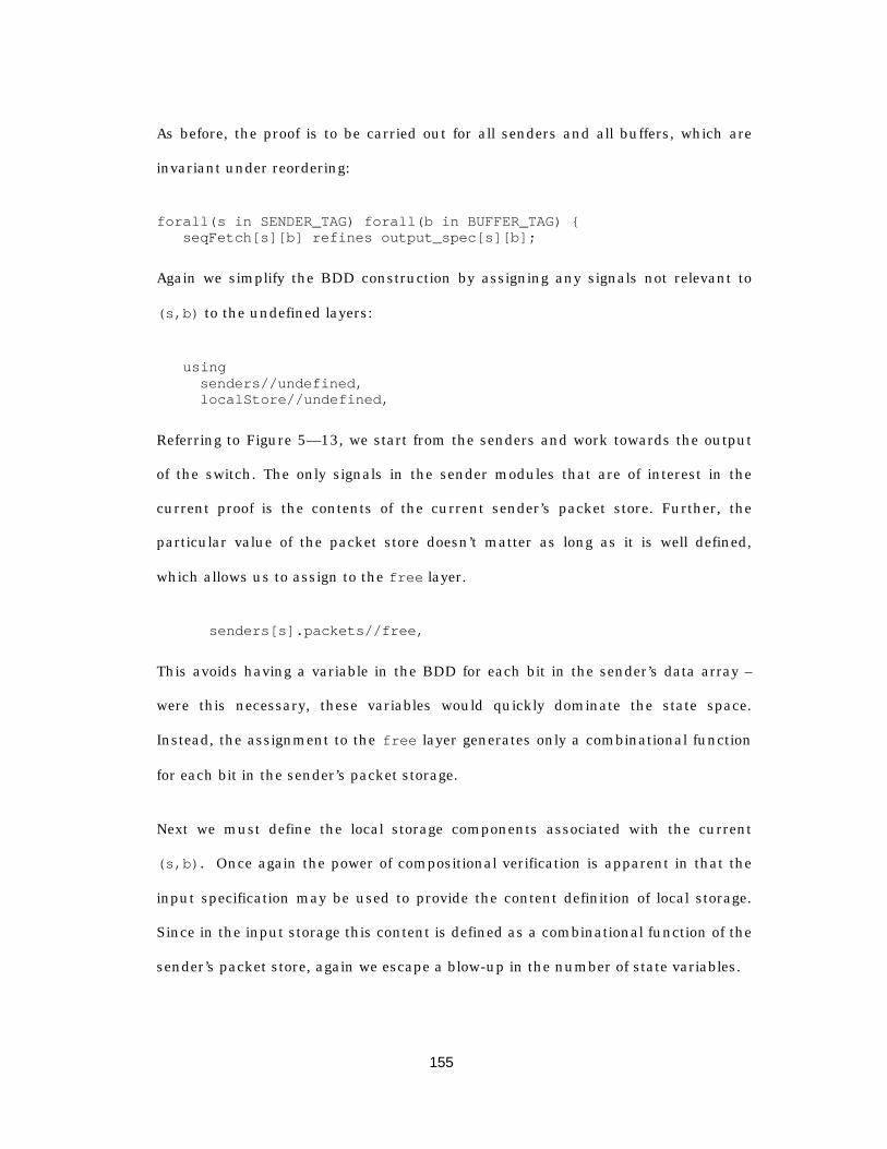
155
As before, the proof is to be carried out for all senders and all buffers, which are
invariant under reordering:
forall(s in SENDER_TAG) forall(b in BUFFER_TAG) { seqFetch[s][b] refines output_spec[s][b];
Again we simplify the BDD construction by assigning any signals not relevant to
(s,b) to the undefined layers:
using senders//undefined,
localStore//undefined,
Referring to Figure 5— 13, we start from the senders and work towards the output
of the switch. The only signals in the sender modules that are of interest in the
current proof is the contents of the current sender’s packet store. Further, the
particular value of the packet store doesn’t matter as long as it is well defined,
which allows us to assign to the free layer.
senders[s].packets//free,
This avoids having a variable in the BDD for each bit in the sender’s data array –
were this necessary, these variables would quickly dominate the state space.
Instead, the assignment to the free layer generates only a combinational function
for each bit in the sender’s packet storage.
Next we must define the local storage components associated with the current
(s,b). Once again the power of compositional verification is apparent in that the
input specification may be used to provide the content definition of local storage.
Since in the input storage this content is defined as a combinational function of the
sender’s packet store, again we escape a blow-up in the number of state variables.
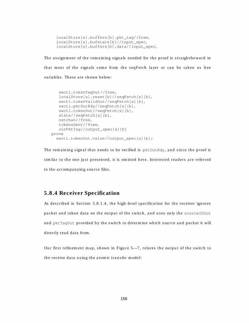
156
localStore[s].buffers[b].pkt_tag//free, localStore[s].bufstate[b]//input_spec, localStore[s].buffers[b].data//input_spec,
The assignment of the remaining signals needed for the proof is straightforward in
that most of the signals come from the seqFetch layer or can be taken as free
variables. These are shown below:
swctl.tokenTagOut//free,localStore[s].reset[b]//seqFetch[s][b],
swctl.tokenValidOut//seqFetch[s][b], swctl.pktOutRdy//seqFetch[s][b], swctl.tokenOut//seqFetch[s][b],
state//seqFetch[s][b],nxtchan//free,
tokensSent//free, curPktTag//output_spec[s][b] prove swctl.tokenOut.value//output_spec[s][b];
The remaining signal that needs to be verified is pktOutRdy, and since the proof is
similar to the one just presented, it is omitted here. Interested readers are referred
to the accompanying source files.
5.8.4 Receiver Specification
As described in Section 5.8.1.4, the high-level specification for the receiver ignores
packet and token data on the output of the switch, and uses only the sourceIDOut
and pktTagOut provided by the switch to determine which source and packet it will
directly read data from.
Our first refinement map, shown in Figure 5— 7, relates the output of the switch to
the receive data using the atomic transfer model:
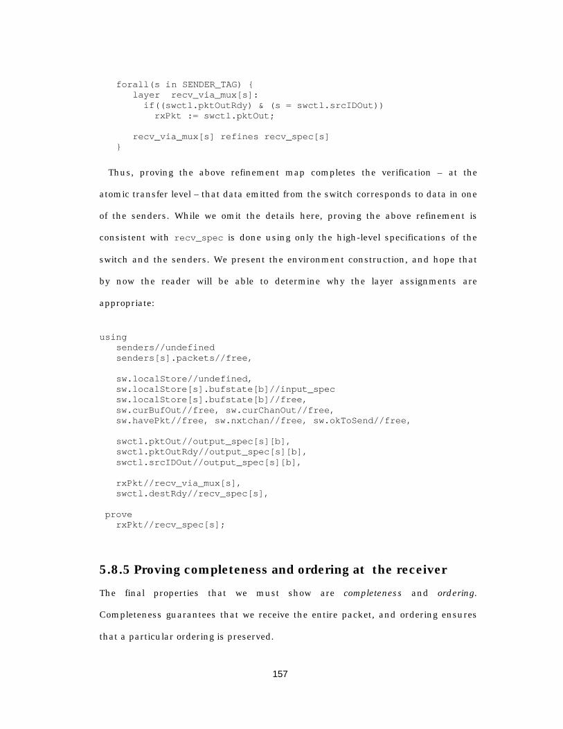
157
forall(s in SENDER_TAG) {layer recv_via_mux[s]:
if((swctl.pktOutRdy) & (s = swctl.srcIDOut)) rxPkt := swctl.pktOut;
recv_via_mux[s] refines recv_spec[s]}
Thus, proving the above refinement map completes the verification – at the
atomic transfer level – that data emitted from the switch corresponds to data in one
of the senders. While we omit the details here, proving the above refinement is
consistent with recv_spec is done using only the high-level specifications of the
switch and the senders. We present the environment construction, and hope that
by now the reader will be able to determine why the layer assignments are
appropriate:
usingsenders//undefinedsenders[s].packets//free,
sw.localStore//undefined, sw.localStore[s].bufstate[b]//input_spec sw.localStore[s].bufstate[b]//free, sw.curBufOut//free, sw.curChanOut//free, sw.havePkt//free, sw.nxtchan//free, sw.okToSend//free,
swctl.pktOut//output_spec[s][b],swctl.pktOutRdy//output_spec[s][b],
swctl.srcIDOut//output_spec[s][b],
rxPkt//recv_via_mux[s], swctl.destRdy//recv_spec[s],
prove rxPkt//recv_spec[s];
5.8.5 Proving completeness and ordering at the receiver
The final properties that we must show are completeness and ordering.
Completeness guarantees that we receive the entire packet, and ordering ensures
that a particular ordering is preserved.

158
To show completeness, we maintain an (abstract) array of boolean variables in the
receiver tokens_recvd[TOKEN_TAG] , where if tokens_recvd[j] is true, then the
token with tag j= has been seen by the receiver. When the receiver sees the
pktOutRdy signal, it assigns the data tokens in its local buffer according to whether
the corresponding token tag has been seen (the following is from the recv_seq[s]
layer):
if (swctl.pktOutRdy & (s = swctl.srcIDOut)) forall(t in TOKEN_TAG)
if(tokens_recvd[t] = true) rxPkt.data[t] := swctl.pktOut.data[t];
Thus, if any token has not arrived by the time pktOutRdy is asserted, then some
for some value of t, rxPkt.data[t] will be undefined. Thus, proving that
rxPkt.data//recv_seq is consistent with rxPkt.data//recv_via_mux (and by
transitivity, is consistent with the receiver specification) guarantees that
completeness holds.
5.8.5.1 Breaking symmetric structures
Until now, we have made heavy use of symmetry to reduce the number of proof
obligation and to split our models into independent components that each provide
functionality for a single sender, buffer, or even token. In proving ordering
properties, unfortunately, we are unable to make use of symmetry. However, by
postponing the symmetry breaking behavior until the last, it becomes a simple
matter to show that a particular ordering is consistent with an arbitrary ordering.
For this example, we use a simple linear ordering on token tags, and the receiver
counts the number of received tokens in the current packet.
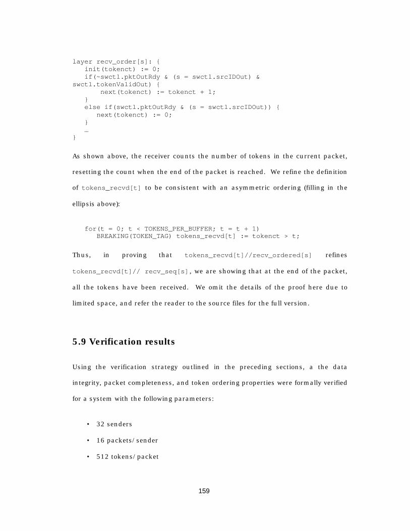
159
layer recv_order[s]: {init(tokenct) := 0;
if(~swctl.pktOutRdy & (s = swctl.srcIDOut) &swctl.tokenValidOut) { next(tokenct) := tokenct + 1; } else if(swctl.pktOutRdy & (s = swctl.srcIDOut)) { next(tokenct) := 0; } …}
As shown above, the receiver counts the number of tokens in the current packet,
resetting the count when the end of the packet is reached. We refine the definition
of tokens_recvd[t] to be consistent with an asymmetric ordering (filling in the
ellipsis above):
for(t = 0; t < TOKENS_PER_BUFFER; t = t + 1) BREAKING(TOKEN_TAG) tokens_recvd[t] := tokenct > t;
Thus, in proving that tokens_recvd[t]//recv_ordered[s] refines
tokens_recvd[t]// recv_seq[s] , we are showing that at the end of the packet,
all the tokens have been received. We omit the details of the proof here due to
limited space, and refer the reader to the source files for the full version.
5.9 Verification results
Using the verification strategy outlined in the preceding sections, a the data
integrity, packet completeness, and token ordering properties were formally verified
for a system with the following parameters:
• 32 senders
• 16 packets/sender
• 512 tokens/packet
160
• 64 bits/token
The running time for the verification was approximately 30 minutes, and was
dominated by the verification that ordered transfers are contained by a system of
unordered transfers.
Counting only the number of bits in the packet memories, the equivalent state
space for this configuration is 2 232 16 512 64 224¥ ¥ ¥ = states, which is to date the largest
known system that has been formally verified.

161
Chapter 6
A n I m p l e m e n t a t i o nMe thodo l ogy f o r Embedded
S y s t e m s
6.1 Overview
The preceding chapters have focused on the problem of moving from an informal
specification to a formal model of the state machines that model the protocol, and
in the preceding chapter we considered an informal approach to moving from a
high-level, atomic-transfer model (e.g., SDL) to an implementation in synchronous
hardware. In this chapter, we consider the problem of moving not just to hardware,
but to a system that consists of a mix of hardware and software.
A key feature of the data link protocols that we are interested in is that the
granularity of time typically spans between 6 and 8 orders of magnitude. Low-level
functions in the media access protocol that directly manipulate the
transmit/receive interface typically operate on the order of a symbol period, which
162
for our systems is usually in the range of 0.1 to 10 microseconds. For this reason,
most implementations will include both hardware and software.
For example, the frequency-hopping modems used in the InfoPad implementation
require the interface logic to “ramp” the power amplifier on over a period of several
microseconds. Similarly, when switching from one frequency to another the
modems require a 100 microsecond “settling time” during which the analog
circuitry reaches a steady-state operating point. Using these modems efficiently
requires tight timing control on the interface to the modems. Thus at least a
portion of the media access protocol is most naturally implemented in synchronous
hardware that operates at a rational multiple of the symbol period.
However, high-level protocol functionality in both the media access protocol and
the logical link protocol are more easily implemented in software. Adjacent cell
monitoring and reporting accumulated link quality statistics are tasks that execute
at intervals on the order of 1 to 10 seconds. This low-frequency operation, along
with the flexibility afforded by a fully programmable implementation, means that
many such tasks can be mapped to an embedded processor. Thus, our
implementation is highly likely to contain a mix of hardware and software.
The data link protocol provides a “packet” interface to the network layer, and in the
design of the state machines for the data link protocol we would like to start at a
packet-processing level of abstraction. Instead of starting with an implementation
language, we would first like to reason about the protocol at a high level,
abstracting away the mechanics of moving data through an implementation, and
focus only on the reactive behavior of the finite state machines in the protocol (i.e.,
the generation of packets and the response to arriving packets).
163
The media access protocol has a much closer interaction with the hardware
because it must control some part of the modem. The state machines that define
this behavior are almost entirely control-oriented, with little if any data flow.
Further, the state machines are usually highly dependent on time intervals that are
typically expressed as multiple of a symbol period.
In this domain, it is unclear if the asynchronous FSM semantics of SDL are
appropriate, since the implementations are almost always synchronous. Also, a
FSM in SDL can only retrieve a single message (i.e., event) from its input message
queue during each instant of execution. On the other hand, controller modules that
are implemented in synchronous hardware usually process multiple events in a
single instant.
This discrepancy points to an underlying problem that is commonly overlooked by
many designers: specification languages are useful for capturing the salient
features only. Languages such as SDL are not suitable for creating a cycle-accurate
model of the implementation, but instead are useful for modeling the system at a
higher level of abstraction.
For example a state machine in a time-slotted MAC protocol might switch the radio
on, transmit N symbols, and switch the radio off. An SDL model of such a system
might abstract the packet transfer into a series of events:
1) a “dead-time” timer expires, marking the start of the transmission
2) the radio is switched on; the packet (i.e., signal) is sent via an “output” action;
and a “stop transmit” timer is set
3) the “stop-transmit” timer expires and the radio is switched off

164
This sequence of events captures three crucial features: dead-time duration, a
message send, and a transmit-time duration. It abstracts the byte-by-byte, or
symbol-by-symbol transmission details that would be present in the
implementation, and instead focuses on the salient property that transmissions
can only occur within certain pre-determined periods.
Thus, in the process of protocol design, we will find that we are required to think
and work at several levels of abstraction. The challenge is to be comfortable moving
between models of computation and being able to discern when to use the high-
level abstraction and when to use a more detailed implementation view. Since
formal relationships between all of the various levels of abstractions are not
possible, some interaction on the part of the designer is still required to be able to
map a higher level to a lower one.
Before we proceed with the problem of mapping a high-level SDL description onto a
mixed-system implementation, we pause to further consider the role that a high-
level specification language plays in the design. Following that, we address the
system partitioning problem by using an architectural template for both the
protocol description and the implementation. Finally, we present a real-time
microkernel operating system that has been implemented and used in the InfoPad
system, and which can be used to provide the infrastructural support required for a
mixed-system implementation.
165
6.2 The relationship between specification languages andimplementation
Ideally, we would like to be able to reason about protocols at a high level of
abstraction and be able to map a high-level model down onto an implementation.
Further, we would like an assurance that the implementation formally conforms to
the specification.
The difficulty in realizing this design flow lies in the fact that high-level models are
abstractions that by definition are intended to gloss over implementation details.
Intentionally, implementation-level details are removed in order to 1) simplify the
specification task by focusing on only the most essential features, and 2) allow the
system designer the latitude to optimize the implementation to a variety of criteria.
That is, a specification should not attempt to include all of the implementation
detail.
A consequence of using an abstraction is that some implementation behaviors are
either impossible or impractical to describe using the specification language. For
example, consider a system in which two process rely on the values of “shared”
variables, and each process is free to modify the values of the shared variables.
Since SDL disallows the use of shared variables, an SDL model of the system might
include a third “memory process” that is the keeper of the variables (see Figure 6—
1).
In SDL, the most natural way of modeling the reading and writing of variables is by
using synchronous remote procedure calls that are actually build on top of a
hidden message-passing mechanism in which an implicit channel between the
server and client processes exist. When the client process executes the remote
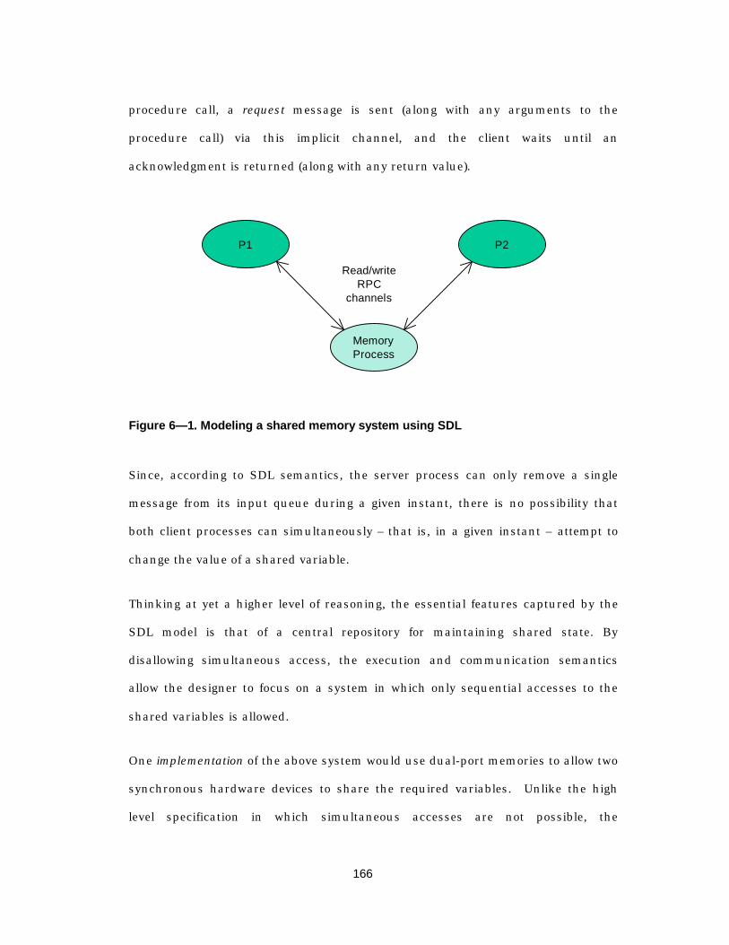
166
procedure call, a request message is sent (along with any arguments to the
procedure call) via this implicit channel, and the client waits until an
acknowledgment is returned (along with any return value).
P1
MemoryProcess
P2
Read/writeRPC
channels
Figure 6— 1. Modeling a shared memory system using SDL
Since, according to SDL semantics, the server process can only remove a single
message from its input queue during a given instant, there is no possibility that
both client processes can simultaneously – that is, in a given instant – attempt to
change the value of a shared variable.
Thinking at yet a higher level of reasoning, the essential features captured by the
SDL model is that of a central repository for maintaining shared state. By
disallowing simultaneous access, the execution and communication semantics
allow the designer to focus on a system in which only sequential accesses to the
shared variables is allowed.
One implementation of the above system would use dual-port memories to allow two
synchronous hardware devices to share the required variables. Unlike the high
level specification in which simultaneous accesses are not possible, the
167
implementation of the “client” processes in synchronous hardware is capable of
simultaneously requesting a write to the same memory location during the same
clock cycle. For deterministic behavior (highly desirable in an implementation), the
implementation must include an arbitration unit that insures mutually exclusive
writes to the same location, along with a protocol for requesting, granting, and
insuring fairness in the accesses.
If the purpose of the specification is to detail the behavior of the client processes
while assuming that an implementation for the memory process exists, then the
arbitration logic and protocol detail is irrelevant in a high-level specification.
The point here is that languages and computational models are tools for
abstraction, and depending on the level of abstraction, one model is better than
another. Attempting to directly map from one domain to another often leads to
inefficiencies or is simply awkward. Instead, high-level models can be used to
simplify the process of deciding what the protocol must do, and the role of a formal
language at this stage is that it eliminates ambiguity in the resulting description.
Implementations embody a set of decisions about how the result is achieved, and
automatically mapping between specification and implementation is still an area of
active research.
6.3 An architectural template for wireles s systems
One approach to mitigating the mapping problem is to restrict both the protocol
systems and the possible implementation architectures. Since the “abstract”
specification really defines a class of implementations, one can choose a subset by
defining an “implementation template” that predetermines some parts of the

168
architecture and implementation. The loss of some generality and flexibility can be
offset by the ability to develop and reuse a library of implementation components
with well-understood and adequately characterized high-level abstractions. This
library can be created manually and tested extensively, easing the mapping for the
class of protocols of interest.
To develop such an architectural template we will need several pieces of
information:
1) An architectural template that defines the physical resources (hardware,
microprocessor, DSP, etc.) that are typical in the implementation domain
(wireless, mobile communications)
2) A functional model of that partitions the protocol into processes that will be
implemented in software and processes that will be implemented in hardware
3) A model of the communication between hardware processes, between software
processes, and between hardware and software processes
The first problem restricts the implementation space to implementations that would
be suitable for the domain of wireless, mobile computing. Systems with an ultra-
high performance microprocessor, or multiple microprocessors could be ruled out
for portable applications. Thus, we will look for a general architecture that would
be suitable for the constraints of portable, handheld devices that must be low-cost,
small form-factor, and energy efficient.
The second problem is one of taking a very general specification and breaking it
into smaller pieces that can be mapped onto hardware or software. Such decisions
are based on a rather complex set of tradeoffs that include factors such as energy

169
efficiency, throughput constraints, how frequently a task is executed, and the
flexibility and cost advantage of implementing in software.
The third problem is that of providing an infrastructure that is consistent with the
abstractions provided by the high-level specification language. For example, SDL
processes communicate over channels that provide a logical inter-process
communication path; a process sending a signal cannot specify the delivery
mechanism that moves a signal to the destination process. Thus, to provide a
natural mapping between an SDL process and an implementation process, we
would like to provide an infrastructure that provides a service equivalent to the
SDL channel.
Tools that create an executable software implementation of an SDL system are
commercially available. Typically, these tools consist of a code generator that
creates a collection of C language procedures that correspond to SDL processes.
The execution environment consists of a scheduler and a set of user-supplied
library routines (e.g., system clock, interprocess communication primitives) that
provide a message-passing interface between the SDL system and the
“environment”.
Since our goal is to map onto a mixed hardware/software, we will need a modified
strategy that will allow us to selectively map pieces of the SDL system onto a
hardware implementation and map other pieces onto a software system. By
designing a set of interface routines that provide the infrastructural glue between
the hardware and software, we can develop a reusable methodology.
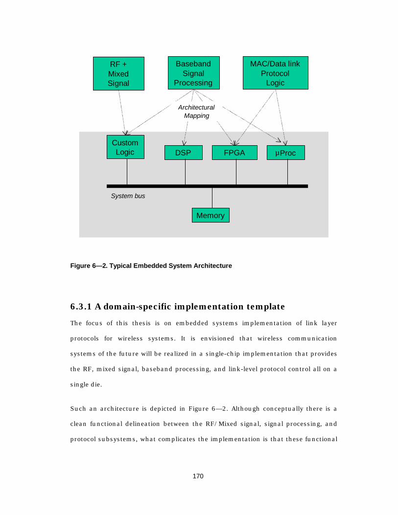
170
RF +MixedSignal
BasebandSignal
Processing
MAC/Data linkProtocol
Logic
µProcDSP FPGACustomLogic
System bus
Memory
ArchitecturalMapping
Figure 6— 2. Typical Embedded System Architecture
6.3.1 A domain-specific implementation template
The focus of this thesis is on embedded systems implementation of link layer
protocols for wireless systems. It is envisioned that wireless communication
systems of the future will be realized in a single-chip implementation that provides
the RF, mixed signal, baseband processing, and link-level protocol control all on a
single die.
Such an architecture is depicted in Figure 6— 2. Although conceptually there is a
clean functional delineation between the RF/Mixed signal, signal processing, and
protocol subsystems, what complicates the implementation is that these functional

171
lines begin to blur. For example, the media access protocol typically controls part of
the functionality of the other two subsystems.
The power amplifier in a transmitter, for example, can be controlled by both the
media access and the data link protocols. In a half-duplex frequency-hopping
transceiver, the power amplifier must be shut down prior to changing frequencies.
Digital circuitry in the signal processing layer may also be controlled by logic in the
data link protocol, as in the case of variable-rate error correction coding1.
At the block-diagram level, there are few differences between such a device and the
InfoPad portable terminal architecture presented in Chapter 2. What they have in
common is a mixture of custom-logic components, reconfigurable-logic
components, and general-purpose processor that are connected via communication
paths (busses).
Ideally, we would like to be able to take functional blocks from each of the high
level domains (mixed signal, DSP, and protocol) and map these blocks down onto
the desired architecture, and have an automated way of generating the necessary
infrastructural “glue.” Unfortunately, this capability does not yet exist. For the
present purpose, we restrict our attention to the problem of mapping the functional
units of the protocol down onto our architectural template.
1 Typically error correction coding is associated with the data link layer (above the mediaaccess layer in the OSI stack). With a variable rate code, there must be controller thatdictates which decoding algorithm is to be used, perhaps powering down other decoder logicthat is temporarily unused.

172
6.3.2 A template for computation and communication inmixed hardware/software implementations
Figure 6— 3 depicts a logical model of the architectural template for an embedded
system implementation of a system of communicating finite state machines. The
system consists of a collection of state machines that are mapped onto either a
software process or a hardware process. These state machines communicate using
either message passing or by using a direct read/write to evaluate or modify a
variable in another process.
The execution environment consists of an interprocess communication API that
supports both of these communication mechanisms. The high-level specification for
any of the processes sees the same API, independent of where the process will be
implemented.
HP1 HPN…SP1 SPN…
Interface Fabric
HW/SW IPC LayerSW/HW IPC Layer
IPC Abstraction Layer IPC Abstraction Layer
Figure 6— 3. Architectural template for embedded system implementation
173
6.3.3 Partitioning strategy: the SDL process as the smallestpartitioning unit
The architectural template described in the preceding section provides a framework
that will allow us to map SDL processes onto either a hardware or software process
in the implementation. One of the tenets of this thesis is that link-level protocols
for high-bandwidth, low-latency wireless communication in portable devices must
be tailored with the implementation domain in mind. Bandwidth efficiency, energy
efficiency, and support for mobile networks cannot be ignored in the design of the
protocol system. Thus, at least in the structural partitioning of functionality, the
specification must have some consideration of the possible implementations.
Because of this, it is not unreasonable to require the specification to partition
functionality into indivisible units that can be directly mapped to a software or
hardware process. Our approach is to jointly consider the implementation template
as the formal (SDL) specification is developed, and to use the SDL process as the
smallest unit of partitioning. These processes are later assigned to either hardware
or software resources, and the appropriate interprocess communication support
can be generated. In designing each process we will consider its likely
implementation – whether hardware or software – and will attempt to avoid
designing a process that will end up being partitioned into a partial hardware and
partial software implementation.
For example, the IEEE 802.11 protocol requires MAC entities to maintain a
“network allocation vector” that tracks, to the extent possible, media access
requests by other MAC entities. When a station needs to use the media, it sends a
short “request to send” (RTS) that includes the transmit duration of the following
payload to the destination station. The destination responds with a “clear-to-send”
174
(CTS) message that also includes the length of the upcoming payload packet. Any
listening station who hears such an exchange is required to note the length of the
payload (plus a following “acknowledgement” packet) as part of its network
allocation vector, and it must refrain from using the media until its network
allocation vector is cleared.
It would be possible to capture this functionality in a single state machine that
encapsulated all of the required behavior, but the resulting state machine would
handle events that span about 6 orders of magnitude of time duration. If this state
machine were described as a single SDL process it would be impossible to partition
the functionality onto the appropriate hardware and software elements of a typical
implementation.
An alternative strategy, and one that would be much better suited for mapping to a
mixed system, is to partition the system along lines of similar time granularity.
Thus, in our example, we might identify a state machine that tracks the network
allocation vector and puts the rest of the system to sleep when the network is to be
occupied for a sufficient period. Another state machine might handle the low-level
bit-to-word construction, and a third state machine might interpret these incoming
words to determine how the network allocation vector should be updated.
With this guiding principle for our specification, we are able to utilize commercial
code generators to produce the code for the processes that are mapped to software.
For the processes that are mapped to hardware, the refinement approach presented
in the previous chapter can be employed. What remains is to provide the
communications interface between the hardware and software, and the execution
environment for the software processes.
175
6.3.3.1 System partitioning and code generation
In the current SDL specification, there is no provision for partitioning a system or
for specifying execution priorities among processes. Commercial SDL tools provide
code generation directives that are embedded in the comments or informal text of
the SDL specification.1 These directives allow the user to specify the partitioning
granularity for code generation along SDL block and process boundaries.
These code generation tools assume that the entire system is to be mapped to
software, and that operating system support will be used to provide the
infrastructure. Since our implementation will include a mix of hardware and
software, a precise mapping from SDL to our hybrid system is difficult, since the
synchronous hardware subsystems and the microprocessor execute independently.
Once again, an informal mapping is used whereby we capture the essential features
of the SDL model in the final system, but lose the ability to formally verify if the
implementation behavior implies the specification behavior.
6.4 Interprocess communication support
SDL defines several interprocess communication primitives that are of interest for
hardware/software implementations: asynchronous message passing, synchronous
remote procedure call, and imported/exported variables. Each of these
mechanisms is built on top of an underlying asynchronous message passing
architecture. The first mechanism, pure message passing, is based on signals (i.e.,
1 I would like to thank Tommy Eriksson of Telelogic, Inc., for the donation of the SDLanalysis and code generation tools.
176
messages) and channels1. Signals can be sent between processes, and the channels
that carries a signal either delivers it immediately to the receiver’s input queue or
delays it for a non-deterministic duration. This communication is asynchronous in
that the sender does not wait for the receiver.
The second mechanism is based upon remote procedure call, where a process
synchronously calls a procedure that is located remotely in another block or
process. In this way, the RPC client can modify variables in the RPC server process.
The final mechanism is based upon import/export variables. An exported variable
declared in one process can be read by another process via the import mechanism:
an implicit set of signals between the exporter and the importer exist, and an
attempt to import actually generates a request/response message exchange that is
invisible to the two processes.
In the following sections, we present a system that supports these communication
semantics using a combination of hardware and software.
6.4.1 Supporting the hardware/hardware interface
Communication between hardware modules is supported via the refinement
methodology presented in the previous chapter. We start with a set of SDL
processes and map them informally to a high-level "behavioral" SMV specification.
This SMV specification is then refined using a series of incrementally more detailed
behavioral models until a cycle-accurate model of the hardware implementation is
1 Here we use “channel” to include both SDL signalroutes (process-to-process) and SDLchannels (block-to-block)

177
reached. The consistency of each refinement is verified using the SMV model
checker.
To facilitate the mapping between SDL communication primitives and a hardware
implementation primitives, we define a "process template" as shown in Figure 6— 4.
The finite state machine logic in the center of Figure 6— 4 corresponds to the
hardware processes in Figure 6— 3, and the interfaces between the FSM logic and
the input/output registers and buffers correspond to the interprocess
communication “abstraction layer” depicted in Figure 6— 3.
In the following sub-sections, we outline the refinement strategy for each of the four
SDL interprocess communication mechanisms and show how they map onto the
various parts of the process template. We note that the mapping is currently
performed manually, though tools for automating the procedure are under
investigation.
Readable
Registers
Mailbox
Registers
InputPacket Buffers
Write
InputR
eadInput
Messaging Input
FSM Logic
InputSignals
OutputPacket Buffers
Messaging O
utput
Write
Output
Read
Output
OutputSignals
Figure 6— 4. Hardware process template

178
6.4.1.1 Hardware-to-hardware message passing
The SDL semantics of message passing have 3 key abstractions that are usually
inapplicable in a hardware implementation: asynchronous finite-state machines,
private communication channels between processes, and atomic execution of a
message send or message receive.
Our refinement strategy is to relate the SDL description informally (i.e., manually
translate) to an SMV specification, changing only the asynchronous FSM
abstraction. That is, the "messaging input/packet buffers" and "messaging
output/packet buffers" shown in Figure 6— 4 have a top layer that is a
synchronous FSM that accepts "atomic" message inputs and generates "atomic"
message outputs. The user defines refinement maps (cf. Section 5.4) that relate the
implementation to this top-level view.
6.4.1.2 Hardware-to-hardware import/export
Imported and exported variables in SDL rely on a policy and a protocol for
synchronizing copies of an "exported" variable. The protocol consists of an implicit
request by the importer (requesting the current value of the variable), and a
corresponding response by the exporter. This protocol is transparent to the user,
but nevertheless must be supported by an implementation.
The process template of Figure 6— 4 supports exported variables via the set of
“readable registers.” The address space for the entire system can be viewed as a
tree with the global address space at the root. Each node in tree corresponds to a
subspace of its parent's address space, so that each readable register is mapped
into the deepest node in the tree that is a common ancestor of the all the
“importing” processes.
179
An import operation is refined by starting equating an import with a read operation
that non-deterministically stalls the importing process until the exporting process
actually exports the variable. This specification is refined into an implementation
that includes a bus (or perhaps a point-to-point connection) protocol that
implements the read.
6.4.1.3 Hardware-to-hardware remote-procedure call
Remote procedure calls in hardware are equivalent to a request/response pair that
is similar to the import/export mechanism described above. The RPC client
synchronously sends a message to the server process, which reacts to the message
(executes the procedure) and perhaps returns a value. The communication is
synchronous in that the client waits for the server to complete the procedure.
The RPC scheme can be modeled in hardware using a set of mailbox registers,
where the client writes to the server’s mailbox to initiate the procedure, and the
server writes back to a client to indicate the response. The high-level specification
for the client uses a write-stall-resume sequence, where the stall is non-
deterministic. The user must refine this specification into an implementation
provides the bus logic.
6.4.1.4 Hardware-to-hardware design exampl e:implementation of the IPBus
The IPBus described in Chapter 2 is one example of a system that supports the
communications primitives described in the preceding sections. The basic interface
architecture is shown in Figure 6— 5, and can be broken down into 5 main
sections:

180
1) bus “master” – allows a device to initiate transfers to a “slave” device
2) the bus “slave” – allows a device to respond to transfers from a master device
3) bus interface logic – includes request and grant logic, as well as prioritized
arbitration
4) interrupt encoder logic – asserts an external interrupt line in response to one or
more internal interrupt conditions
5) register file – provides “mailbox” and “readable” registers described above
FIFO
FIFO
Master Channel
Slave Channel
IP Address[7:0]
IP Data[7:0]
IP Address[7:0]
IP Data[7:0]
status register
InterruptEncoder
data register
Bus Arbitration
Logic
Address[7:0]
Data[7:0]
FIFO Interface
FIFO Interface
Data[7:0]
Address[7:0]
RegisterFile
Figure 6— 5. IPBus interface architecture
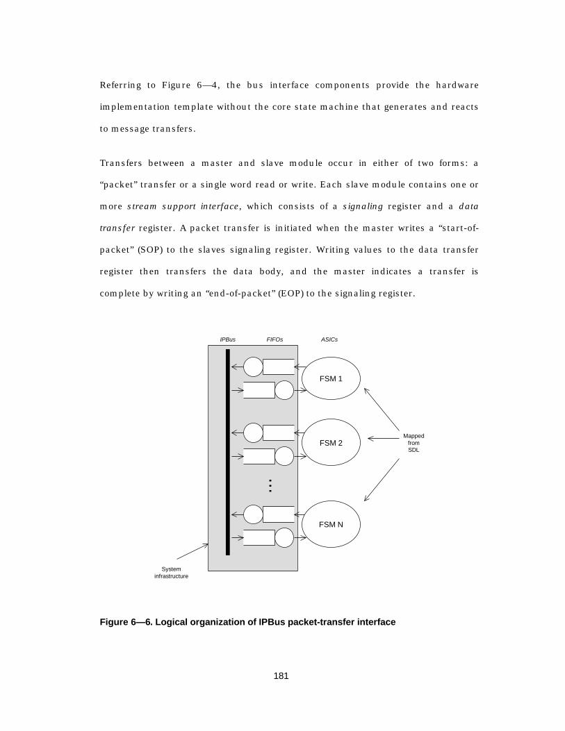
181
Referring to Figure 6— 4, the bus interface components provide the hardware
implementation template without the core state machine that generates and reacts
to message transfers.
Transfers between a master and slave module occur in either of two forms: a
“packet” transfer or a single word read or write. Each slave module contains one or
more stream support interface, which consists of a signaling register and a data
transfer register. A packet transfer is initiated when the master writes a “start-of-
packet” (SOP) to the slaves signaling register. Writing values to the data transfer
register then transfers the data body, and the master indicates a transfer is
complete by writing an “end-of-packet” (EOP) to the signaling register.
...
FSM 1
FSM 2
FSM N
IPBus FIFOs ASICs
MappedfromSDL
Systeminfrastructure
Figure 6— 6. Logical organization of IPBus packet-transfer interface
182
Figure 6— 6 depicts the logical configuration for interprocess communication using
the packet transfer mechanism. Each finite state machine (supplied by the user)
feeds messages into an output FIFO, and consumes incoming messages from the
input FIFO.
During system initialization, each bus master is given a set of target addresses. A
target address is used to determine the bus address of the slave module to which a
particular message is directed. Thus, since the FSMs see only a FIFO interface, the
system is able to provide a set of virtual channels over a shared bus transparently
to the FSMs that are generating and reacting to the messages.
In the design of InfoPad, the FSMs were designed using a hardware description
language (VHDL or Verilog). The primitives of these languages are well-suited for
implementation, but are cumbersome to use when focusing only on the message-
passing behavior of the FSMs. A better strategy is to use a high-level language such
as SDL to describe, simulate, and verify the behavior of the FSMs, followed by the
refinement strategy described in the previous chapter to design the final
implementation.
The other data transfer mechanism directly reads from or writes to a register. In
principle, this mechanism can be used for emulating remote procedure calls and
for imported/exported variables. In the implementation of the InfoPad signal
processing components, however, hardware-to-hardware RPC and import/export
was not a construct that was used. (These were used between the software and
hardware modules, and will be discussed later sections).

183
6.4.2 Mapping the SDL model to software
As described in Chapter 3, the execution semantics of SDL is that of asynchronous
finite state machines that execute in parallel. Each process is a state machine that
has a single input message queue. When a process has a non-empty input queue,
it retrieves a single message from the queue, not-necessarily in FIFO order,
evaluates the message, perhaps produces output messages, and changes state
instantaneously. The communication channels that connect these state machines
introduce a non-deterministic delay (perhaps zero) before delivering a message.
6.4.2.1 Scheduling policies
The execution semantics of this model can be mapped onto a multi-threaded
software application in which threads communicate using message passing (no
shared memory). To mimic the SDL semantics, when a thread is scheduled for
execution it must remove a single message from its input queue, process it, and
generate any output messages instantaneously – that is, time cannot advance
during the transition from one state to another. However, since the times at which
enabled transitions actually fire is non-deterministic, the semantics of SDL assume
nothing about the relative execution rates between processes. Hence the class of
allowable thread scheduling policies is quite large.
6.4.2.2 Advancing time
A second consideration is that of the SDL semantics of advancing time. When a
process executes a transition in SDL – thus marking the “end” of the current
instant – a non-deterministic choice is made to either execute another process or to
expire the earliest active timer. The non-deterministic choice enforces the
184
semantics of asynchronous execution in that the designer cannot assume anything
about the execution rates of processes.
If the choice is made to execute another process, the system time does not advance.
However, if the timer expires, three things happen:
1) The system time advances by the duration of the timer
2) An “expired timer” message is inserted at the head of the input queue of the
process that started the timer
3) This process executes
Since the processes execute asynchronously, the case where two timers expire at
exactly the same instant is disallowed (otherwise there would be a synchronization
point).
The implication of these semantics is that if a timer expires, the process that
started the timer must run before any other timer expires. Thus, a software
scheduler must insure that when a timer expires, the process are waiting on that
timer execute before any other timer expiry is visible to the processes.
6.5 IPos: operating system support in the InfoPad system
Having the hardware/hardware and software/software execution and interprocess
communication models in hand, we now consider the support features required of
the operating system. The primary roles of the operating system in this context are
to
185
1) Provide the execution environment for the software threads
2) Provide the software/software and hardware/software communications
primitives
The general constraints on the software execution environment have been
described in Section 6.4.2, and the model for the hardware execution environment
and hardware/hardware communication in 6.4.1. At this point, we consider the
InfoPad operating system, IPos, as one possible approach to addressing the
complete system design, including both the execution environment, the software
interprocess communication primitives, and the low-level support for the
software/hardware communications interface.
One way to view the execution model of SDL processes is that of event-driven,
reactive components. Each FSM executes only when there is a message available,
and when it finishes processing the message it terminates execution.
A programming model for event-driven systems employs “callbacks.” Given a set of
message-processing procedures and messages types, during system initialization
the procedures are registered as “handlers” for one or more message type. When
the operating system receives a message of a given type, the appropriate handler
procedure is notified, or “called back.”
IPos utilizes this callback paradigm to provide a mechanism for event-driven
programming that is especially common in protocol systems. The additional
infrastructure that the operating system must provide (for the systems described in
Section 6.4.2) consists of a scheduler, a concept of time, and miscellaneous
“housekeeping” functions such as memory management.
186
The architecture of IPos can be separated into 5 primary entities
• data sources and data sinks
• streams
• timers
• a kernel (scheduler, memory manager, etc.)
We discuss each of these architectural components in the following.
6.5.1 Data sources, sinks and streams
Referring to Figure 6— 3 (page 172), our system model includes hardware
processes, software processes, and support for interprocess communication. In
IPos, a source generates messages, and a sink consumes messages. (It is possible
that a process acts as both a source and a sink.) It is assumed that the complete
set of possible process instances are known at compile time. Each process, whether
hardware or software, is assigned a unique tag that corresponds to a procedure
address (for software) or a physical address (for hardware).
A stream is a logical path for unidirectional information flow from a source to a
sink. As with SDL channels that support multiple message types (signal types), so
IPos streams support multiple message types. When a stream is created and
initialized, the list of message types are declared, giving the kernel hints about how
much memory to allocate for queues and buffers for a given stream.
A stream is created using the following kernel routine:
stream_Create(source id, sink id, message set);
187
6.5.1.1 Hardware-hardware and software-software source sand sinks
Each hardware source, as depicted in Figure 6— 4, contains an output messaging
block that contains a set of target registers that are used to determine the
destination address of a particular message as follows.
During a partitioning step, the designer identifies where each process in the system
will be mapped – either to hardware or to software. Further, the designer specifies
the possible communication paths (i.e., streams) between each process, together
with the allowable message set that is to be supported by each stream. A kernel
function, IPInit(), is responsible for initializing the system, and in this routine each
stream is explicitly created – regardless of whether the source and sink are both in
hardware, there must be a creation point in the IPos initialization code.
When a stream is created, the kernel determines if the source is a hardware
process. If so, for each message type the device is capable of generating, the kernel
sets the target address register to the address where messages of the specified type
should be sent. When the hardware module transfers a message, it uses the
message type to determine where the current token (i.e., byte) of the current
transfer should be directed. From the perspective of the hardware device transfer
mechanism, transfers to another hardware device are indistinguishable from
transfers to a software process.
An example hardware data source is the depacketizing module (“RX chip”) that
accepts frame-synchronized bytes from the modem interface and routes these bytes
to the appropriate data source. Since each packet from the wireless link must
specify its message type, the RX module is able to determine the destination for the
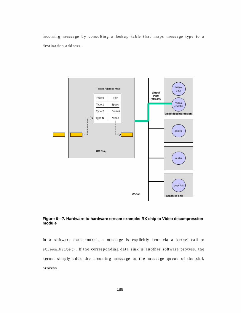
188
incoming message by consulting a lookup table that maps message type to a
destination address.
Type 0
Type 1
Type 2
Type N
Pen
Speech
Control
Video
Target Address Map
Videocodebk
Videodata
graphics
control
audio
RX Chip
Graphics chip
Video decompression
IP Bus
VirtualPath
(stream)
Figure 6— 7. Hardware-to-hardware stream example: RX chip to Video decompressionmodule
In a software data source, a message is explicitly sent via a kernel call to
stream_Write(). If the corresponding data sink is another software process, the
kernel simply adds the incoming message to the message queue of the sink
process.

189
6.5.1.2 Crossing the hardware/software boundary
IPos provides an abstraction layer that presents the illusion of symmetry between
hardware and software data sinks. Given with a map of system memory, the IPos
kernel is able to determine during stream creation whether a particular source or
sink address is in hardware or software. As explained earlier, if the source is a
hardware device the kernel simply initializes a target register in the hardware
device; if the source is a software thread, the kernel allocates buffer space
proportionally to number and size of messages that the source can generate.
The IPos kernel also presents an abstraction layer for message transfers between
hardware and software. When a software source sends data to a hardware sink,
IPos immediately accepts the incoming message from a software process and
buffers it until it can be transferred to the hardware device, consistent with the
semantics of instantaneous message “sends” over channel that non-
deterministically delays its messages. Transfers from hardware to software are
typically spread out over time, so the IPos kernel buffers incoming data until a
complete packet is received. This packet is then placed in the input queue of the
destination process, and at some time in the future the presence of a packet in the
input queue enables the process to be executed.
An integral part of this abstraction layer is a hardware “bridge” that provides a
physical interface between the microprocessor subsystem and the I/O processing
components described in Chapter 2 (e.g., speech, text, graphics, etc.). The
architecture of the bridge is shown in Figure 6— 8.
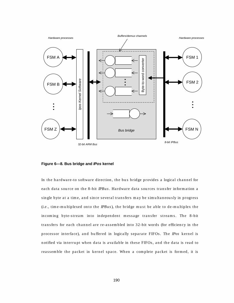
190
FSM 1
FSM 2
FSM N...
Byt
e-to
-wor
d co
nver
ter
Ipos
Ker
nel S
oftw
are
Hardware processesBuffers/demux channels
FSM A
FSM B
FSM Z
... ...
8-bit IPBus32-bit ARM Bus
Hardware processes
Bus bridge
Figure 6— 8. Bus bridge and IPos kernel
In the hardware-to software direction, the bus bridge provides a logical channel for
each data source on the 8-bit IPBus. Hardware data sources transfer information a
single byte at a time, and since several transfers may be simultaneously in progress
(i.e., time-multiplexed onto the IPBus), the bridge must be able to de-multiplex the
incoming byte-stream into independent message transfer streams. The 8-bit
transfers for each channel are re-assembled into 32-bit words (for efficiency in the
processor interface), and buffered in logically separate FIFOs. The IPos kernel is
notified via interrupt when data is available in these FIFOs, and the data is read to
reassemble the packet in kernel space. When a complete packet is formed, it is

191
placed in the input message queue for the callback procedure that is registered for
the given message stream and message type.
In the software-to-hardware transfer direction, the bridge provides a 64-word by
40-bit FIFO. The lowest 8 bits of the FIFO are used directly to determine the IPBus
address for the outbound word, and the upper 32 bits are transferred as a series of
4 single-byte transfers.
Thus, the IPos kernel and the bus bridge provide an abstraction layer that emulates
the transfer semantics of instantaneous message sends and message arrivals with
non-deterministically delayed communication channels between processes.
6.5.2 Timers
Protocols usually require some notion of timers or time-out events. Especially at
the media access control level, timing is important because many access strategies
use a form of time division multiplexing to regulate access to the channel, and
timing skew results in either collisions or requires unacceptably large guard times
that reduce the efficiency of the MAC protocol. Since we are supporting hardware
and software processes, our timer mechanism must support “timer events” for both
hardware and software.
The difficult with mapping SDL timers directly to hardware lies in the single input
queue abstraction used in SDL – as noted previously, the implication of the single
input queue is that each process can only consume one event during a given
transition. Thus, in SDL when a timer expires a timer event is inserted into the
input queue of the process that set the timer, and unless otherwise specified this
event is processed in the order in which it appears in the input queue.
192
In synchronous hardware, on the other hand, it is possible that a bus transfer
occurs during the same cycle in which a timer expires, a situation that cannot be
explicitly represented in SDL. Thus in hardware the designer is forced to either
handle both simultaneously or to preserve the SDL model of computation in which
one event is processed before the other.
In software, however, the problem is one of handling real-time tasks that must
quickly respond to a timer event. Since in SDL a transition occurs instantaneously,
it is possible to service an expired timer immediately upon expiry by using a
“priority input” in the process that is waiting for the timer. In an implementation,
however, processes do not execute instantaneously, so it is possible that a low
priority task can completely starve a higher priority real-time task.
The approach that has been taken in the IPos kernel is to use a combination of
preemption and delayed procedure calls. A real-time (hardware) timer periodically
interrupts the kernel at a rate that exceeds the frequency of the most-frequently-
occurring task. Each time the kernel receives a timer interrupt, it checks the set of
active timers to determine if one has expired. If so, the kernel immediately calls the
associated “handler” routine that is specified when the timer is set.
Here the realities of practical implementations must be merged with the
impracticalities of an abstract specification. The user must decide whether the
timer handler routine is fast enough to allow it to execute at a non-interruptible,
non-preemptible priority. Updating a software clock, for example, can usually be
handled without difficulty. Longer tasks, on the other hand, must be split into a
timer handler and a delayed procedure call: the handler simply creates a “timer
expiry” event and places it in the input queue of the process that set the timer. This
event is later processed through the usual mechanism for scheduling processes.

193
6.6 Current status and possible extensions
This chapter focused on the problem of starting with an abstract protocol
specification that modeled the system as a set of communicating finite state
machines and mapping down to an implementation in a system where the protocol
implementation consists of both hardware and software components. The key idea
is that by restricting the implementation domain (embedded systems that have an
architecture such as that in Figure 6— 2) as well as the protocol domain (media
access and data link protocols), we can ease the problem of mapping from the
abstract specification to the detailed implementation. The argument is that by
understanding the likely architecture of the implementation, we can partition and
structure the specification in such a way that the mapping becomes
straightforward.
The obvious limitation on the methodology presented in this chapter is that it
presupposes details about the implementation during the structuring of the
specification. Normally one seeks to remove all implementation dependencies from
a specification in order to allow maximum flexibility in the implementation.
However, the architecture chosen is relatively general and commonly thought to be
typical of next generation wireless systems. By fixing some aspects of the
implementation and folding these into the specification, we are able to rapidly
define and prototype communication systems, and are able to evaluate new
protocols. Given that wireless communication for portable computing devices is still
in its infancy, it is our belief that the reduction in generality is fully justified by the
ability to experiment with new protocol systems.
194
Currently, the mapping from SDL to C and to SMV (which is refined to hardware
using the methodology presented in the preceding chapter) is done manually.
Commercial code generators are available, but their overall limitation lies in the
fact that they fail to distinguish between a specification language (SDL) and an
implementation language. Since they attempt to map the full (or almost full) set of
SDL constructs and semantics onto a software implementation, the resulting
implementation are typically not well suited for partitioning into hardware and
software units. Further, they are usually too code-heavy to use in an embedded
system with a limited amount of memory.
A better strategy for facilitating the mapping from SDL to C and SMV is to take the
structural aspects of SDL (blocks, processes, channels), and require the user to
manually (or automatically, if possible) map these structural units onto physical
resources such as hardware, software, and buses. Given this mapping, an
automated tool could map the functionality of an SDL process onto either hardware
or software. The scheduler, timers, and interprocess communications support are
provided by the embedded operating system.
In summary, relating a specification to an implementation is a complex process.
Many designers confuse the roles of a specification language and try to directly use
it as an implementation language, rather than leveraging the power in the
abstractions that a specification language offers. By restricting the space of
implementations to a particular architectural template, we enable the designer to
structure the specification in a way that can be more easily mapped onto the pre-
determined architecture, but the price is that the approach is not completely
general.
195
Chapter 7
P r a c t i c a l s t r a t e g i e s f o ri n t e g r a t i n g f o r m a l m e t h o d s
in p r o t o co l des i gn andi m p l e m e n t a t i o n
7.1 Overview
Given the overall goal of integrating a formal description technique into the protocol
design flow, it is beneficial to consider a complex system design example to discover
the strengths and limitations of a formal approach. We take as our example the
InfoPad System [TPDB98][NSH96], and work from the informal and formal
constraints to develop a fully functional protocol. The early protocol design efforts
used only informal state diagrams; these are presented for a few of the key system
196
entities, and the corresponding formal (SDL) descriptions can be found in the files
accompanying this thesis1.
Our primary context is in link layer protocols, and as discussed earlier these link
protocols typically consist of a logical link control portion and a media access
control portion. This chapter focuses on the communication protocols and state
machines that are implemented in the InfoPad system, with the goal of identifying
tradeoffs between several approaches to modeling the various components of the
protocols. We focus predominately on the MAC and logical link protocols that are
implemented in the multimedia terminal; however, because much of the logical link
control protocols involve centralized management functions located on the
backbone network, it is necessary to include some of the backbone networking
entities in our example2.
7.2 An informal system-level specification
The first step in the design of a protocol system is to determine the services that
the protocol is supposed to provide, along with any constraints that the system
must satisfy (e.g., a minimum throughput or maximum latency requirement). At
the highest level of abstraction, the InfoPad system is required to provide mobile
access to multimedia services that reside on a backbone network, and the portable
device is intended to serve only as a remote I/O interface to a “virtual device” that
runs on the backbone network. A subjective constraint on this high-level view of
1 The files can be obtained via anonymous FTP onhttp://infopad.eecs.berkeley.edu/infopad-ftp/theses/truman.
2 We would like to acknowledge the efforts of the InfoNet group in designing andimplementing the backbone network software, enabling a much broader body of research.
197
the system is that the protocols must hide the mobility from the servers and the
clients.
7.2.1 Delay, bandwidth and reliability constraints
Two global requirements for the system are that 1) it must support real-time,
interactive multimedia applications that run remotely on a wired network, and 2)
that it should present the user with the appearance that the applications are
running locally on the mobile device. This implies high-bandwidth, low-latency
access to the backbone network. Specifically, the downlink (from base to mobile)
was to required to support full-motion video (0.4 – 1.0 Mbits/sec) and audio
streams (64 Kbits/sec) along with graphics (100 – 300 Kbits/sec) and protocol
control data. The uplink was required to support audio (64 Kbits/sec), pen input (8
Kbits/sec), and protocol control data (1 Kbit/sec).
In addition to these bandwidth requirements, the “remote I/O” paradigm
introduced in Chapter 2 placed very stringent latency bounds on the data transfer
service. In order to preserve the appearance of local execution, a roundtrip “event
processing” delay of 30 milliseconds was imposed on the system. Thus we have
both a throughput and a delay constraint.
An additional limitation of the physical layer was that the best available commercial
modems for the wireless link provided only 650 Kbits/sec half-duplex aggregate
throughput. Thus, the available bandwidth was oversubscribed for the worst-case
bandwidth requirements. To cope with this, the data link protocol was required to
provide data-dependent quality-of-service (QoS) that could statistically multiplex
traffic onto the wireless link and provide a “reliability effort” that was tailored to the
class of data of a particular packet.
198
The interesting aspect about the above constraints is that for the class of data
transfer service that is being provided (real-time multimedia), the constraints are
“soft” in that they are design objectives that are intended to provide subjective
quality. To the extent the system is able to satisfy the constraints, the subjective
quality is maintained. What is difficult, however, is to quantify the effect of failing to
meet the constraints, leaving the system designer with a large number of degrees of
freedom. For example, it is permissible to drop occasional video data blocks due to
a high error rate or to smooth an extended burst of traffic; it is difficult to quantify
the degradation as the fraction of dropped blocks increases.
This points to the underlying challenge in designing wireless communication
systems for real-time systems: typically these systems have some degree of loss
tolerance, and the designer must simultaneously optimize for delay, loss, and
reliability. Since the demand for wireless access is growing much faster than the
available (and usable) bandwidth, it is critical to use the spectrum efficiently by
tailoring the protocol to the class of applications supported. This requires an
understanding of the statistics of the traffic carried (burstiness, delay sensitivity),
the error characteristics of the wireless link, and a knowledge of the sensitivity to
loss. For entirely new designs that include both new applications and new
protocols, perhaps the biggest challenge is bringing all of this knowledge together
simultaneously in order to guide the optimizations and tradeoffs that are required
to produce a working system.
In the design of the InfoPad, the protocols were designed jointly with the system
hardware, software, and multimedia servers. Very little information about channel
characteristics or “remote I/O” traffic patterns was available during the design of
the protocols and the end-user system. For this reason, a large part of the research
199
agenda was to be able to instrument the system so that an evaluation of the
subjective quality for varying delay, loss, and reliability could be performed. Thus, a
design constraint on the protocol system was that it should support a variety of
scheduling, error-control coding, and access schemes. We will return to this idea in
Section 7.3.
7.2.2 System-level services for I/O servers and clients
As described in [SSH96], the backbone services consist of video, graphics, and
audio streams on the downlink (to the mobile), as well as pen and speech servers
that process uplink traffic from the mobile.
One way of reasoning about the system is to use a structural
abstraction/refinement that at the highest level of abstraction views only the data
clients, servers, and an abstract channel that connects clients to servers. This
abstraction clarifies the “message-passing” protocols that are used between
individual servers and clients, and provides the environment or “test bench” for
testing and debugging the data link protocols. Such a view is presented in Figure
7— 1, where each server and client is represented by a different SDL block.
Before moving to the design of the data link protocols, it is worth noting where in
the design flow the system in Figure 7— 1 fits in. In its current form, SDL does not
support stochastic performance modeling, though work on a new SDL standard
(SDL 2000) is in progress and is expected to support this. Thus, the SDL view of
the I/O servers and clients should using enough detail so that it is possible to
verify that the message-passing behaviors satisfy any specified safety and liveness
properties. To verify these properties, it is necessary to know the possible
sequences of message exchanges without respect to the probability of a particular
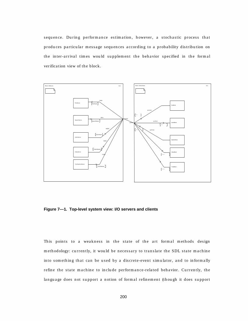
200
sequence. During performance estimation, however, a stochastic process that
produces particular message sequences according to a probability distribution on
the inter-arrival times would supplement the behavior specified in the formal
verification view of the block.
Block IOServers 1(1)
PenServer
SpeechServer
AudioServer
VideoServer
TextGraphicsServer
PNCH
PenPacket
SPCH
SpeechPacket
syschan
AUDDN
AudioPacket
VIDDN
(VideoPackets)
TXTDN
(TxtGrPackets)
Block IOInterfaces 1(1)
PenBlock
AudioBlock
SpeechBlock
VideoBlock
TxtGrBlock
penchan
syschanaudchan
spchchan
Figure 7— 1. Top-level system view: I/O servers and clients
This points to a weakness in the state of the art formal methods design
methodology: currently, it would be necessary to translate the SDL state machine
into something that can be used by a discrete-event simulator, and to informally
refine the state machine to include performance-related behavior. Currently, the
language does not support a notion of formal refinement (though it does support
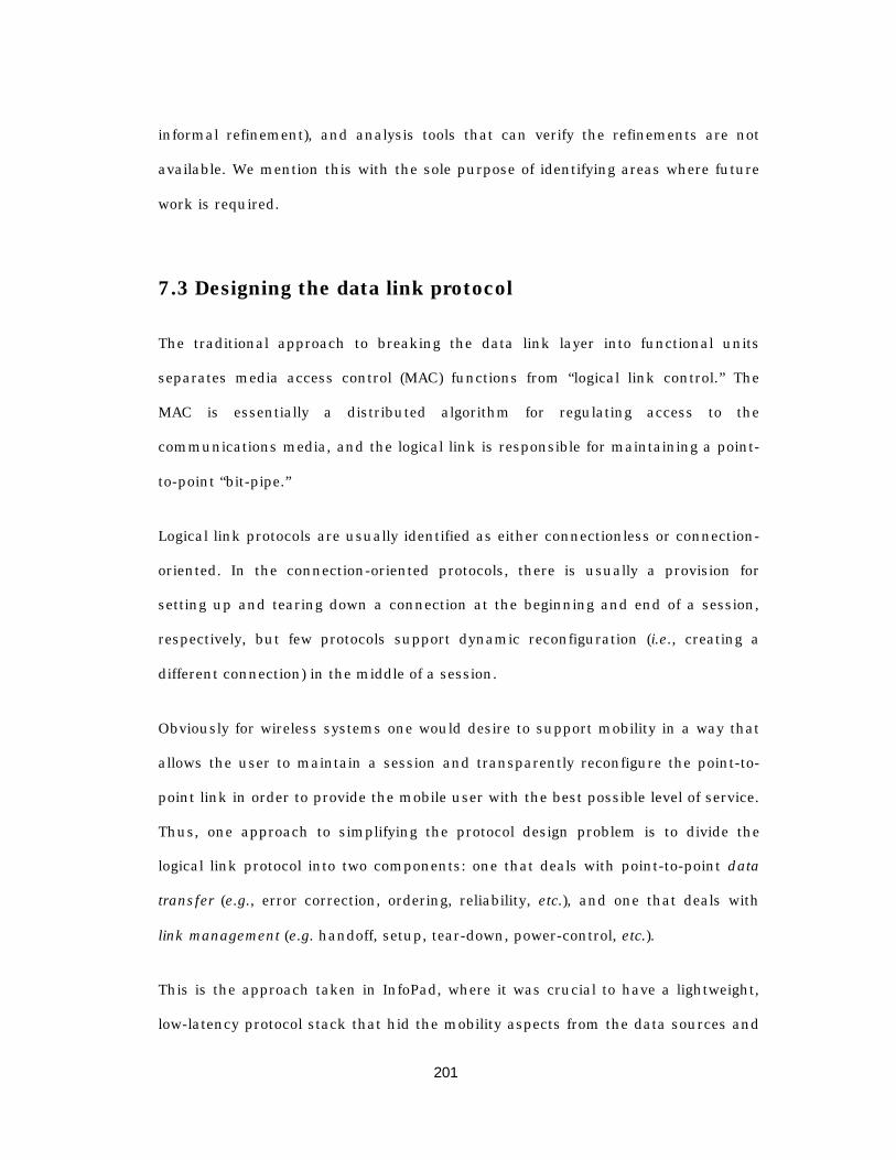
201
informal refinement), and analysis tools that can verify the refinements are not
available. We mention this with the sole purpose of identifying areas where future
work is required.
7.3 Designing the data link protocol
The traditional approach to breaking the data link layer into functional units
separates media access control (MAC) functions from “logical link control.” The
MAC is essentially a distributed algorithm for regulating access to the
communications media, and the logical link is responsible for maintaining a point-
to-point “bit-pipe.”
Logical link protocols are usually identified as either connectionless or connection-
oriented. In the connection-oriented protocols, there is usually a provision for
setting up and tearing down a connection at the beginning and end of a session,
respectively, but few protocols support dynamic reconfiguration (i.e., creating a
different connection) in the middle of a session.
Obviously for wireless systems one would desire to support mobility in a way that
allows the user to maintain a session and transparently reconfigure the point-to-
point link in order to provide the mobile user with the best possible level of service.
Thus, one approach to simplifying the protocol design problem is to divide the
logical link protocol into two components: one that deals with point-to-point data
transfer (e.g., error correction, ordering, reliability, etc.), and one that deals with
link management (e.g. handoff, setup, tear-down, power-control, etc.).
This is the approach taken in InfoPad, where it was crucial to have a lightweight,
low-latency protocol stack that hid the mobility aspects from the data sources and
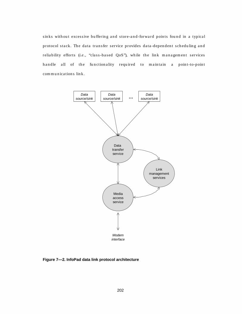
202
sinks without excessive buffering and store-and-forward points found in a typical
protocol stack. The data transfer service provides data-dependent scheduling and
reliability efforts (i.e., “class-based QoS”), while the link management services
handle all of the functionality required to maintain a point-to-point
communications link.
Data transferservice
Linkmanagement
services
Mediaaccessservice
Modeminterface
Datasource/sink
Datasource/sink
Datasource/sink…
Figure 7— 2. InfoPad data link protocol architecture
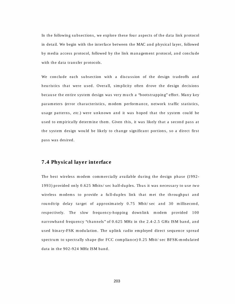
203
In the following subsections, we explore these four aspects of the data link protocol
in detail. We begin with the interface between the MAC and physical layer, followed
by media access protocol, followed by the link management protocol, and conclude
with the data transfer protocols.
We conclude each subsection with a discussion of the design tradeoffs and
heuristics that were used. Overall, simplicity often drove the design decisions
because the entire system design was very much a “bootstrapping” effort. Many key
parameters (error characteristics, modem performance, network traffic statistics,
usage patterns, etc.) were unknown and it was hoped that the system could be
used to empirically determine them. Given this, it was likely that a second pass at
the system design would be likely to change significant portions, so a direct first
pass was desired.
7.4 Physical layer interface
The best wireless modem commercially available during the design phase (1992-
1993) provided only 0.625 Mbits/sec half-duplex. Thus it was necessary to use two
wireless modems to provide a full-duplex link that met the throughput and
roundtrip delay target of approximately 0.75 Mbit/sec and 30 millisecond,
respectively. The slow frequency-hopping downlink modem provided 100
narrowband frequency “channels” of 0.625 MHz in the 2.4-2.5 GHz ISM band, and
used binary-FSK modulation. The uplink radio employed direct sequence spread
spectrum to spectrally shape (for FCC compliance) 0.25 Mbit/sec BFSK-modulated
data in the 902-924 MHz ISM band.
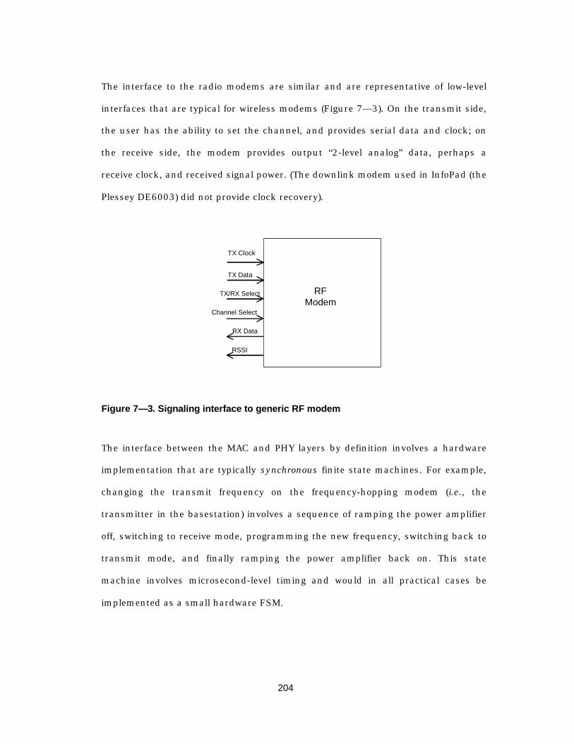
204
The interface to the radio modems are similar and are representative of low-level
interfaces that are typical for wireless modems (Figure 7— 3). On the transmit side,
the user has the ability to set the channel, and provides serial data and clock; on
the receive side, the modem provides output “2-level analog” data, perhaps a
receive clock, and received signal power. (The downlink modem used in InfoPad (the
Plessey DE6003) did not provide clock recovery).
TX Clock
TX Data
TX/RX Select
RX Data
RSSI
Channel Select
RFModem
Figure 7— 3. Signaling interface to generic RF modem
The interface between the MAC and PHY layers by definition involves a hardware
implementation that are typically synchronous finite state machines. For example,
changing the transmit frequency on the frequency-hopping modem (i.e., the
transmitter in the basestation) involves a sequence of ramping the power amplifier
off, switching to receive mode, programming the new frequency, switching back to
transmit mode, and finally ramping the power amplifier back on. This state
machine involves microsecond-level timing and would in all practical cases be
implemented as a small hardware FSM.

205
We draw attention to this point in order to demonstrate to key aspects of the design
methodology. The first is that data link and MAC protocols will involve synchronous
FSMs. The second point is that the “message passing” protocol abstraction
described in Section 5.4is not the most convenient formalism for describing and
implementing these lower-level protocols.
Our experience has been that it is best to capture the salient functional aspects of
the services that these low level protocols provide (e.g., data transfer with non-
deterministic loss and delay) and use a much higher level abstraction of these
layers in the design of the data link protocols.
Returning to the discussion on the interface between the MAC and PHY, these low-
level interfaces place the burden of synchronization on the user. Bit-level
synchronization may be provided by more advanced modems, but in all cases frame
synchronization – that is, finding the boundaries of packets – is left to the user. In
the following subsections, we outline the salient features of the interface logic
required to synchronize the transmitter and receiver.
7.4.1.1 Bit-level synchronization
The frame format for the data link is shown in Figure 7— 4. A 64-bit preamble of
alternating 1’s and 0’s is used to by the receiver to detect a receivable signal, select
an antenna (if diversity is used), and reach steady state in the analog circuitry of
the receiver.

206
Preamble Header Data
Bitsync
64 bits (0101… )
FrameSync
32 bits
HeaderBody
Variable
CRC-16† DataBody
Variable
CRC-16†
Figure 7— 4. Data link frame format
The clock recovery algorithm is based on an oversampling scheme in which the raw
input data stream is oversampled by some factor NSAMPLES (a factor of 10 in the
InfoPad), and “recovering the clock” amounts to choosing one of NSAMPLES
possible sampling points. For maximum immunity to clock or frequency drift, we
would ideally choose the sampling point to be exactly at the midpoint of a symbol
interval (Figure 7— 5).
Oversampledinput
stream
Ideal sampling
points
Figure 7— 5. Clock recovery illustration
To estimate the ideal midpoint of a symbol interval, we maintain a running
up/down counter and compare the current (oversampled) input sample with one
that is delayed by NSAMPLES sample times. If the two are the same, we do nothing.
† Optional header CCITT CRC-16
† Optional body CCITT CRC-16

207
If they are different then we either increment or decrement the counter (if the
current input is 0 and the delayed input is 1, increment; otherwise decrement).
This gives us an estimate of the midpoint of a symbol period. With this estimate,
many sampling schemes can be used to estimate the value of the current symbol.
One approach would be to use a single sample taken at the “ideal” sample point.
Another approach is to use an “early-midpoint-late” scheme where a majority vote
is used to resolve disagreeing sample values. In the InfoPad, an integrate-and-slice
approach is taken, which essentially gives a majority vote from among all of the
NSAMPLES taken during a symbol time.
7.4.1.2 Frame synchronization
The clock recovery algorithm operates in conjunction with a frame synchronization
unit. Initially, a receiver is in a “scan” mode, continuously revising the estimate of
bit-level timing and simultaneously searching for a frame synchronization word in
the incoming bit stream. As shown in Figure 7— 4, the 64-bit symbol
synchronization preamble is followed immediately by a 32-bit frame
synchronization word (four repetitions of 10110101). When the frame
synchronization is in unit recognizes this bit pattern, it declares itself to be
synchronized with the transmitter, and signals the clock recovery unit to lock the
sampling point estimate at the current sampling phase. At the end of a packet, the
frame and bit synchronization units are reset to scan mode, and the procedure is
repeated (Figure 7— 6).

208
oversample
Clockrecovery
Framesync
oversample
Serial data
clock
lock
scan
Figure 7— 6. Interaction of frame and clock synchronization units
7.4.1.3 Discussion of heuristics and design tradeoffs
The timing and frame recovery described above uses the preamble as an adaptive
training period and “opens the loop” once the frame synchronization word is
recognized. The shortcoming in this approach is that it is susceptible to timing
offsets and clock drift between transmitter and receiver.
An alternative method that was explored initially attempted to dynamically track
the bit-level timing throughout the duration of a transmission, adjusting for
mismatches between the transmitter and receiver. However, when a receiver moves
into a frequency null (i.e., fade), the output of the receiver oscillates wildly. Since
the timing recovery algorithm uses transitions in the input stream to form the
sampling point estimate, these high-frequency transitions must be filtered.
However, such a filter necessarily incorporates memory of the past, and hence the
training time of the filter increases proportionally to its ability to smooth noise- or
fade-induced bursts. Several schemes that used variable-window timing recovery
algorithms were explored in order to provide a fast initial synchronization followed
by a slow adaptation once frame synchronization was achieved. All of these
209
approaches required tradeoffs in the complexity and required system resources,
and in isolation it was unclear which approach was most appropriate.
However, considering the design of the physical layer jointly with the range of
supported applications provided clarity for several decision criteria. For network
scheduling efficiency, most packets are short – on the order of 8 bytes for a pen
packet and 40 bytes for a speech packet, for example. Longer packets, such as
video data blocks, were typically no longer than 1 Kbyte. Thus it was desirable to
keep the synchronization preamble as short as possible to maintain bandwidth
efficiency.
An analysis of the need for adaptive timing recovery showed that the gains would
be negligible and would not justify the complexity required for the dynamic tracking
scheme. The oversampling clocks (a 10 MHz clock output of the downlink modem)
were accurate to within 10 parts per million (10 Hz/MHz). Assuming a worst-case
frequency offset of 20 PPM between transmitter and receiver, the drift in the
reconstructed 1 MHz data stream is on the order of 500 milliseconds per symbol.
(Thus, starting from perfect synchronization, the transmitter and receiver require
500 milliseconds to be out of alignment by 1 symbol period). If we allow for an
upper bound on the drift during a packet to be 0.25 bits, we have a maximum
transmit duration of 125 milliseconds, corresponding to about 16 Kbytes, which is
well below the typical “long” 1-Kbyte packets. Given this information, adaptive
timing recovery provides no perceptible improvement over open-loop timing
recovery.
The point here is that designing this layer of the protocol without knowledge of the
end-application can result in significant complexity and lengthen the design cycle.
This black-box separation of functionality is in principle the approach proposed by
210
the OSI protocol. However, by jointly considering the application with the
capabilities of the system, we are able to prioritize the design efforts and avoid
“over-engineering” the system. It is our belief that for the class of applications that
were supported in InfoPad, it was absolutely critical to view the system as a whole,
rather than to independently optimize smaller pieces of the system.
7.4.1.4 Signal strength measurements & antenna diversity
Typical wireless modems provide an analog output signal that provides a measure
of the received power in the frequency band of interest. This signal is digitized and
is used to estimate the quality of the received signal, and can be used to choose one
of several possible receive antennas when antenna diversity is used. The downlink
modems provided two antenna connections and a 4 µsec switching time. In
principle, at the beginning of each transmission the receiver would sample one
antenna, switch to the other antenna and sample, then choose the antenna that
had the highest received signal strength.
The implementation of this portion of the system was not, in hindsight, given
adequate attention. Two critical factors were overlooked in the choice of A/D
conversion modules. First, to capture the received signal strength measurement, a
12-bit A/D1 with a bit-serial interface was chosen to minimize the pin count and
thus board area for the A/D unit. However, this serial interface required 16 data
“clock” pulses to serially generate the 12 bits of output data (the first 4 output bits
were constant 0’s). Since the data clocking interval was constrained to be at least 1
microsecond, the maximum conversion rate was on the order of 64 KHz. Thus, a
1 Analog Devices part number AD8379

211
complete sample-switch-sample-switch sequence requires at least 32
microseconds, or about 4 bytes worth of data. (The antenna selection can be
switched immediately after the first sample is taken).
The second issue that was overlooked initially was the details of the algorithm for
diversity sampling and antenna selection. Suppose that of the two antenna a1 and
a2, one is in a complete frequency null (a1, for example). To maximize the chance
of receiving a packet, the receiver constantly samples a1, switches to a2 and
samples, then switches back to a1 and repeats the process.
Assume that just prior to the start of transmission, the receiver switches to a1,
which is in a complete null. A sample is taken and the receiver switches back to a2
and takes a second sample. Since in the sample of a1 the receiver could not
differentiate between a null and a break in transmission, before the antenna
selection can be made the receiver must again switch to a1.
Preamble Header Data
Sample1
16 bits
Sample2
16 bits
Sample1&
decide
16 bits
Bitsync
64 bits
FrameSync
32 bits
Figure 7— 7. Modified preamble incorporating antenna diversity
Thus, to fully utilize the potential of frequency diversity, the receiver must make 3
samples. Since in this implementation each sample requires at least 16
microseconds, the PHY preamble must be extended to include an additional
“antenna selection” sequence of approximately 48 bits. Since the samples are
simply a measurement of the in-band energy, the receiver still requires a timing
recovery sequence (64 bits in this system), so together with the 32-bit frame sync
212
word, the total preamble length is 144 bits. This implies that a typical 5-byte pen
packet has an overhead of approximately 80%, and a 32-byte speech packet has
approximately a 20% overhead.
Several alternative approaches could produce a more bandwidth efficient
realization. For the class of highly energy efficient receivers discussed in [She96],
having a separate receiver path for each antenna would be a practical and energy-
efficient way to completely eliminate switching between antennas, since the entire
integrated receiver in [She96] required only 27 milliwatts, and the off-the-shelf 12-
bit A/D converter requires 25 milliwatts. Further, for the purposes of deciding
between antennas, a high-resolution A/D is unnecessary: we only need to know
which antenna produces the strongest signal, requiring only a 1-bit comparator to
choose between the antennas/receive arms.
Thus by approaching the problem from a system-level, we can increase both the
energy and the bandwidth efficiency by eliminating a high-resolution A/D and by
eliminating the antenna switching preamble entirely. Again we see that a systems-
level perspective completely restructures the architectural and algorithmic
optimizations.
7.5 Media access protocol for frequency-hopping modems
A well-known aspect of media access protocols is that contention-based access
protocols are inefficient for constant bit rate or isochronous data, and are better
suited to bursty traffic that is less sensitive to delay due to collisions [Tan89]. Since
the RF modem provided only an aggregate throughput of approximately 650
213
Kbits/sec, the wireless link was almost fully utilized. For this reason, the media
access scheme was essentially forced to be a contention-free protocol.
Because the required bandwidth was so close to the maximum bandwidth
supported by the full-duplex link, the primary concern in the media access protocol
was to avoid collisions. Essentially, both the downlink and the uplink employ
frequency-division multiplexing scheme, where each mobile in a cell is assigned a
dedicated channel that is orthogonal to the other mobiles in the cell. (No attempt
was made at coordinating frequency assignments between cells).
The downlink modem, however, supports slow frequency hopping as a form of
whitening the transmit spectra (for use in the ISM band), which also offers a
coarse-grained frequency diversity. Utilizing a frequency-hopping scheme requires
3 synchronization points between the base and the mobile:
1) They must agree on a hopping sequence
2) They must agree on a starting point
3) They must agree on the dwell time, or length of time that a given frequency bin
is occupied
7.5.1.1 Choosing a hopping sequence
The choice of hopping sequence depends upon the objective behind using frequency
hopping. In the following subsections, we present several applications of wireless
modems with a “slow frequency hopping” capability. These systems have in
common a narrowband transmission scheme with a variable offset frequency, and
both the transmitter and receiver are able to select the appropriate offset frequency

214
at a rate that is some multiple of the symbol rate. (For the downlink modem in the
InfoPad, changing the transmit or receive frequency required approximately 100
microseconds, or about 64 symbol periods).
Frequency hopping for coarse-grain frequency diversity
A primary objective for using frequency hopping is to obtain some degree of
immunity against long-duration fades and against interference. Spreading transmit
power over a wider frequency band limits ability of a strong interferer or a deep fade
to impair the quality of the received signal for a long period of time.
With this in mind, one approach to choosing a hopping sequence is to use a
pseudo-random hopping sequence that simply uses a PN generator to choose the
next frequency. Another approach uses physical channel characteristics such as
delay spread or coherence bandwidth and adds a minimum-distance criteria on the
hopping sequence so that no two sequential frequencies fall within the same
coherence bandwidth (the IEEE 802.11 standard uses this approach).
A third possible approach would be to adaptively choose the hopping sequence
based on received signal quality information from the receiver1. However, the
benefit of this approach appears to be mostly applicable to stationary, or mostly
stationary, wireless systems. Measurements taken in the indoor environment using
the InfoPad indicate that for mobile (walking) users, over a time period of 50
milliseconds or more the variation in received signal strength is typically (Appendix
1 There is typically a larger set of available frequencies than a system is required to use, so itis feasible to avoid using certain frequencies for a period of time. The InfoPad downlinkmodem, for example, provided 100 frequency channels; FCC Part 15 requires using only 75of these.
215
A) greater than 9 dB. A protocol that used the signal strength information from
previous transmissions to adaptively chose its hopping sequence in order to
maximize the signal strength would need to determine those times when the
channel quality is changing too quickly for an adaptive algorithm to converge.
Frequency hopping for unregulated systems
Slow frequency hopping it is typically used in “unlicensed” systems in order to
whiten the transmit spectrum by restricting the fraction of time that a given
transmit frequency can be used. For example, the FCC Part 15 regulation on the
2.4-2.5 GHz ISM band restricts a transmitter to a transmit duration of 400
milliseconds in a 30 second interval (forcing the transmitter to use at least 75
different frequencies). A further restriction is usually placed on the coordination
between transmitters to insure some degree of statistical fairness between
unrelated systems that share the same frequency band.
In these systems, efficiency is sacrificed for the opportunity to avoid the regulatory
hurdles and expense of licensing a section of the spectrum for exclusive use. (Here,
efficiency is lost primarily in the form of collisions with other transmissions). A
relatively new IEEE standard, the 802.11 wireless LAN standard falls into this
category.
Slow frequency hopping code division multiple access
A third application for slow frequency-hopped modems uses a form of code-division
multiple access. In this approach, a code is a sequence of frequencies. Instead of a
static frequency allocation as is used in frequency-division multiple access, a user
(or perhaps a group of users that share the same code) sequences through the set
216
of frequencies in the code. Again, the rational behind this scheme is the frequency
diversity that is gained by spreading transmitted power over a much wider
bandwidth.
The most spectrally efficient codes are orthogonal, so that no two users occupy the
same frequency at the same time. However, it is possible to combine other multiple
access techniques with SFH-CDMA in order to allow a group of users to share the
same code.
7.5.1.2 Synchronizing the transmitter and receiver
All of the above applications for slow frequency-hopping systems present the
problem of initial synchronization between transmitter and receiver. Assuming that
the transmitter and receiver agree on the hopping sequence and dwell time, there is
still the initialization problem for the receiver to find the transmitter in the hopping
sequence. Once this synchronization point is determined, the receiver and
transmitter know both the exact dwell time and next frequency in the hopping
sequence, so that they are able to proceed in lock-step. Many schemes exist, and to
give the reader a feel for the general approach taken in networks such as the IEEE
802.11 standard, we discuss a few of the key ideas below.
In all cases a timing master provides the time reference for the local network (or
cell). Given the hopping sequence, a dwell interval, and a starting point t, it is
possible to determine precisely when the timing master will return to the same
frequency. Thus, assuming perfect clocks, given the hopping sequence, the dwell
time, and the remaining time in the current dwell interval, it is possible to predict
where the station will be in the hopping sequence at any time in the system. Thus,
217
for example, if we assume that time is measured in microseconds, we can assign a
unique index to each microsecond in the hopping sequence.
The timing master periodically transmits beacons that announce its network
identification, the selected hopping pattern, and a time stamp that declares the
index of the instant in which the beacon left the transmitter. Given this information
at the receiver, it is possible to predict exactly when the transmitter will next
change frequencies, and since the hopping pattern is known, the transmitter and
receiver are synchronized.
Synchronization schemes typically use a passive scan, an active scan, or a
combination of both. In a passive scheme, a receiver listens for beacons on a given
frequency for a fixed duration, then switches to the next frequency in the hopping
sequence and continues to listen. The rate at which the receiver changes
frequencies is either significantly faster or significantly slower than the transmitter
– which one hops faster is a matter of protocol design, but the basic idea is that one
of the systems eventually overtakes the other. The disadvantage of this case is that
usually the intervals at which beacons are transmitted are fairly long, and if
network traffic is light there is a chance that the receiver and transmitter are at the
same frequency waiting for a beacon timer to expire.
In an active scheme, the unsynchronized mobile proactively transmits a probe
packet and waits for a reply from one or more responders. If after a period of time
the initiator receives no response, the frequency is changed and the process is
repeated. Often, however, the initiator will receive responses from several stations,
and in this case a further negotiation is necessary to determine which responder to
synchronize with.
218
7.6 Link management protocols
One of the design constraints is that the protocol services provided to the I/O
servers and clients should hide the mobility aspects. This constraint is imposed in
order to allow the system to utilize legacy packages that were designed for non-
mobile clients.
Narayanaswami, et al [NSH] describe the basic backbone service architecture that
realizes this objective. As in many systems that support mobile clients, the system
is divided into service areas, or cells. Each cell consists of a Cell Server that services
a number of access points (basestations) that provide the wired-to-wireless network
interface, and the duties of the cell server are primarily to regulate access to these
basestations by either accepting or refusing a request from a mobile client. These
requests may be from mobile clients that are entering the system, or they may be
from clients that are moving within the system.
Each mobile client that is active in the system has a corresponding proxy agent
that exists on the backbone network – the so-called Pad Server. The responsibility
of the Pad Server is to present a “static-client” image to the I/O servers described
above, and to monitor the signal strength measurements reported by its mobile
counterpart.
We present the portions of the initialization and mobility handoff protocols in the
following sections using message sequence charts to illustrate how communicating
processes interact over time. Since Chapter 3 focused specifically on formal
languages, we delayed introducing MSCs until this point.
219
7.6.1.1 Overview of message sequence charts
MSCs are an informal notation that support the notion of processes, states,
messages, timers, and process termination. MSCs document a single execution
history, as they do not support the notion of branching. For example, Figure 7— 8
shows an execution trace of the link establishment protocol in which no packets
are lost or corrupted.
It is worth noting here that because MSCs are an informal notation, they are
perhaps the best place to start the design of a message passing protocol. As a
design aid, formal languages can be too structured during the exploration phase.
MSCs offer a nice compromise because although the language is informal, it is
restricted to a set of constructs that are useful for defining the temporal
relationships between interacting concurrent processes. The lack of structure and
informal notation make MSCs an excellent choice for free-form illustration, but as
the design becomes more detailed and structure or hierarchy becomes desirable,
their applicability becomes limited.
Thus, the role of MSCs in the design methodology begins with the identification of
the possible scenarios and cases that the system must handle. Once these
“specification MSCs” are defined, they can be used to generate a template for a
system of interacting SDL processes, and at that point, the methodology shifts to
working with SDL to flesh out the detailed state machines. The resulting SDL
system can then be simulated to generate a set of execution traces that are
compared to the original MSCs to check that the implementation is contained by
the specification.
220
7.6.2 Establishing the link
As we noted in the previous section, the media access protocols employed
frequency division multiple access with a downlink bit rate of 625 Kbits/sec, and
an uplink of approximately 250 Kbits/sec. Although frequency hopping was
implemented in a prototype, in the working system implementation it was not
employed. Instead, the cell server would assign each mobile client a fixed downlink
frequency and a set of alternate frequencies of adjacent cells that could be
monitored for possible handoff requests.
The uplink modem supports 4 non-overlapping (e.g., non-interfering) channels of
approximately 250 Kbits/sec raw throughput. For the prototype network, each cell
supported only 2 mobile clients, each with a dedicated uplink frequency, and all
cells shared a common contention-based “control” channel on which mobiles can
request resource allocation.
Initially, the mobile listens for a beacon on a predetermined control channel. When
it receives a beacon, it initiates a request to join the cell by sending a JOIN
REQUEST to the backbone network. This request is forwarded to the cell server,
which decides whether or not to allow the mobile to use the cell’s resources. If the
request is rejected, the mobile must wait for a beacon from another cell or must
attempt to join at some time in the future.
If, however, the request is granted, a series of events happen. First, the cell server
reserves an uplink and a downlink channel for the mobile. Second, the cell server
sends a message to the mobiles “static proxy”, the pad server, indicating that the
mobile is now a part of a session in the current cell. The pad server records the

221
logical network address for the mobile (i.e., the current cell) so that it is able to
redirect network connections directly to the gateway that is serving the mobile.
Once the pad server updates its connections to the mobile, the cell server responds
to the mobile by sending a JOIN ACK message, indicating that the request has been
accepted and specifying the exact resource allocations that have been made. The
mobile uses the assigned uplink and downlink channels for further communication
with the backbone network.
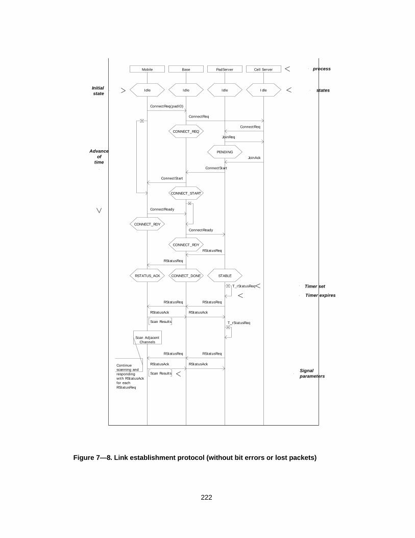
222
Mobile Base PadServer Cell Server
IdleIdleIdleIdle
ConnectReq(padID)
ConnectReq
CONNECT_REQConnectReq
JoinReq
PENDINGJoinAck
ConnectStart
ConnectStart
CONNECT_START
ConnectReady
CONNECT_RDYConnectReady
CONNECT_RDYRStatusReq
RStatusReq
CONNECT_DONERSTATUS_ACK STABLE
T_rStatusReq
RStatusReq RStatusReq
RStatusAckRStatusAck
Scan Results T_rStatusReq
Scan AdjacentChannels
RStatusReqRStatusReq
RStatusAck
Scan Results
RStatusAckContinuescanning andrespondingwith RStatusAckfor each RStatusReq
process
states
Timer set
Timer expires
Signalparameters
Advanceof
time
Initial state
Figure 7— 8. Link establishment protocol (without bit errors or lost packets)
223
7.6.3 Maintaining the link
Once the link has been established, the pad server periodically sends requests for
status reports from the mobile. (Indicated by the repeated RstatusReq and
RstatusAck messages at the bottom of Figure 7— 8). These requests contain a list of
adjacent channels that are to be scanned by the mobile, and their received signal
strengths are to be reported to the pad server. This information is used by the pad
server to initiate a handoff or to adjust the transmit power on the downlink.
Alternatively, if the signal quality degrades for an extended period of time, the
mobile can itself request either an increase in transmit power or a handoff to an
adjacent cell.
The protocol for handing off a mobile from one cell to another is an excellent
candidate for the formal verification methods we described in Chapter 3. Typically,
a handoff involves at least 2 gateways, 2 cell servers, a pad server, and the mobile
itself. All of these processes are exchanging messages with the goal of maintaining
a consistent view of shared state that is distributed throughout the network, and it
is a simple matter to introduce timing dependencies or deadlock into the system.
7.6.3.1 Handoff between cells
Figure 7— 9 presents the MSC for a perfectly executed handoff (without lost or
corrupt packets that would imply retransmission). Starting with the system
successfully initialized and the mobile connected to Cell0, the MSC indicates the
procedure for migrating the connection to Cell1.
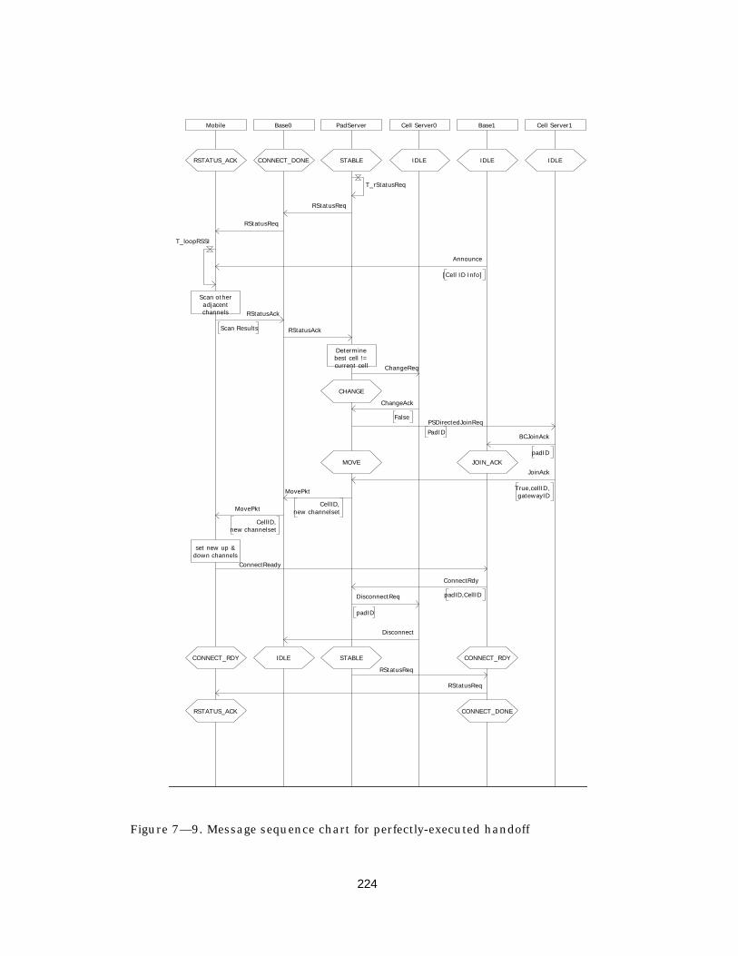
224
Mobile Base0 PadServer Cell Server0 Base1 Cell Server1
IDLEIDLEIDLESTABLECONNECT_DONERSTATUS_ACK
T_rStatusReq
RStatusReq
RStatusReq
T_loopRSSI
Announce
[Cell ID Info]
Scan otheradjacentchannels RStatusAck
Scan Results RStatusAck
Determinebest cell !=current cell ChangeReq
CHANGE
ChangeAck
FalsePSDirectedJoinReqPadID BCJoinAck
padIDJOIN_ACKMOVE
JoinAck
True,cellID,gatewayIDMovePkt
CellID,new channelsetMovePkt
CellID,new channelset
set new up &down channels
ConnectReady
ConnectRdy
padID,CellIDDisconnectReq
padID
Disconnect
STABLECONNECT_RDY IDLE CONNECT_RDY
RStatusReq
RStatusReq
RSTATUS_ACK CONNECT_DONE
Figure 7— 9. Message sequence chart for perfectly-executed handoff

225
If during a routine scan of adjacent channels it is discovered that the mobile has a
significantly better received signal from Base1 of Cell1, the Pad Server sends a
ChangeRequest to the Cell Server. In turn, the Cell Server will attempt to increase
the quality of the received signal – this may entail an increase in transmit power or
an increase in coding rate.
If the Cell Server is unable to increase its reliability effort, it indicates this by return
a negative response with the ChangeAck message. (The case where the Cell Server
returns a positive response is not shown in Figure 7— 9, and would require a
different MSC). With the negative response, the Pad Server decides to initiate a
handoff by choosing from among the adjacent cells the cell with the best received
signal strength (as determined by the result of the last scan result message).
When the target cell is determined, the Pad Server sends a PSDirectedJoinReq to
the cell, indicating that it wants to join the cell. Assuming the target cell is capable
of servicing the request and allocating the required resources, the target cell
chooses a basestation (i.e., gateway) in its jurisdiction and reserves it for the
incoming mobile. The target cell returns an acknowledgment to Cell0, indicating the
ID of the new basestation that the mobile is to use. When the Pad Server receives a
JoinAck from the target cell, it sends a Move message to the mobile device
indicating the IDs of the target cell and basestation.
Before continuing with the protocol, it is useful to think about a snapshot of the
system at this stage in the handoff procedure. Two cells and two basestations have
resources reserved for the pad and are awaiting further interaction from the mobile
before proceeding to a stable state. This is a point of extreme vulnerability to
deadlock or livelock – if the mobile goes to sleep or suddenly moves out of range or
is in a deep shadow, a well defined procedure for backing out of the handoff must

226
be defined. We will return to this point later in the discussion about formal
verification.
Continuing with the protocol description, assuming the mobile receives the Move
message, it uses the target cell and base IDs, along with the indicated uplink and
downlink frequencies, to determine the new channels to use. The mobile then
sends a ConnectReq to the target cell, which ends the handoff from the mobile’s
perspective. The backbone network then must tear down the old connection, and
once this is complete the system returns to a state that is similar to where we
picked up, but with the mobile connected to Cell1 instead of Cell0.
7.7 Formal description and verification o f the system
The message sequence charts presented so far indicate only a very small portion of
the link management protocol – specifically, those paths through the state space
where errors and exception conditions are not considered.
The absence of conditional branching MSC processes serves to keep the
interactions simple and relatively straightforward because it is impossible to define
an “if-then” behavior — each conditional branch requires a new MSC. While this is
useful in the case-by-case specification, for large designs it becomes difficult to
propagate changes to and from corresponding SDL descriptions as the design
begins to take shape.
With the goal of using formal verification to check for logical inconsistencies and for
safety and liveness, we move to formal language description. The link management
protocol has been analyzed and described in two different formal languages: SDL
and Promela, both of which were described in Chapter 3. During the actual design
227
of the protocol (1993), tools for formal analysis had not progressed to a state where
they would substantially contribute to the implementation of the protocol, so it was
felt that designing directly in an implementation language such as C or VHDL was
the only practical solution.
Since then, formal languages and supporting tools have matured, and to evaluate
the usefulness of these formal methods, the implementation was translated into the
both SDL and Promela. In Appendix B, a Promela model is provided, and the SDL
models can be obtained via anonymous FTP. In the following section, we present a
qualitative discussion about the relative strengths and weaknesses of both of these
languages – both with regard to suitability for design and specification as well as
for formal verification.
7.7.1 Message Sequence Chart specifications
As described previously, MSCs a language with informal semantics – that is, there
is no formal model of state transition, time advancement, or inter-process
communication. Thus it is not possible to formally prove temporal properties about
an MSC specification directly. In fact, since there are no execution semantics, it is
impossible to execute or even simulate an MSC.
However, message sequence charts can be used as a form of language containment
(in the automata-theoretic sense). Given an implementation or a specification in a
formal language such as SDL, it is possible to check that an execution of some
portion of the system generates a message sequence that is contained by an MSC
or a set of MSCs.
228
The informality and lack of structure in MSCs that are assets early on in the design
become a limitation as the design is fleshed out. Each conditional branch in the
transition system generates a separate MSC, and explicitly and individually
covering all of the possible executions of the system becomes impossible for
systems of reasonable complexity. Our experience has been that it is most useful to
choose a small subset of key interactions use MSCs as a starting point for
understanding, documenting, and visualizing the interaction between
communicating concurrent processes.
7.7.2 SDL specifications
As the design process continues, SDL becomes a more suitable choice for formally
specifying the interactions, tasks, and data types1. As explained in the preceding
chapter, SDL is best suited for detailed message-passing interaction between
processes that execute asynchronously. When particular algorithms are chosen
and a structural view of the system is required, SDL provides the necessary
mechanisms to capture these aspects of the design.
The richness of SDL as a specification language becomes its greatest liability as a
front-end language for formal verification. It is possible, for example, to define
systems with an infinite state space (e.g., unbounded recursion). However, the most
common tendency is to specify a finite-state system that is simply far too large to
be formally verified using model checking.
1 SDL does support an informal text construct

229
For example, the SDL model of the InfoPad link management protocols includes 6
processes: a single mobile device, two basestations, two Cell Servers, and one Pad
Server. If each of these processes has only 4 bits of state, there are 224 states in the
system, and depending on the number of transitions, this may already be out of
reach for automated verification tools.
7.7.3 Promela
As a final look at the relationship between specification languages, system design,
and formal verification tools, we consider the Spin [Hol89] model checking system
and its front-end language, Promela (PROtocol MEta LAnguage).
Since Promela is intended for use as a verification language, it is optimized for
specifying possible behaviors, rather than probable behaviors. For example,
Promela is an untimed language that supports an abstract notion of a timeout: if all
processes are waiting on an input (i.e., no processes can be scheduled) and one of
the timers has a reachable timeout statement, then the timeout event occurs. If two
or more timeout events are executable, then one is chose randomly.
While this is suitable for completely random execution and verifying the system
under no timing assumptions, it can significantly complicate the description. For
example, in the link management protocol each cell sends a beacon every second or
so to provide an opportunity for the mobiles in the cell to resynchronize with the
base and sample the received signal strength. Thus, one way of modeling this
behavior in Promela is to specify a timeout that, when it executes, generates an
Announce packet.
230
However, a reliable data transfer protocol has a timeout mechanism to account for
lost or corrupted packets. The timeout duration for the data transfer protocol is on
the order of 1-2 milliseconds, approximately 1000 times as infrequent as an
announce packet.
If time granularity is considered, it is possible to abstract the above system to say
that given the choice between an Announce timeout and a “retransmit packet”
timeout, the retransmission should always occur. Completely removing the
assumption of time results in a system in which any number of Announce packets
can be generated between a retransmission, and results in a significantly more
complex specification.
One solution to the above problem would be to have a priority structure among
timeouts, or perhaps equivalence classes of timers. What one would like to say is
that any time a high-priority (i.e., fast-expiration) timer is enabled, it is impossible
for a low-priority (or longer-expiration) timeout to occur.
Along with the intricacies of modeling the interactions between processes, Promela
does nothing to address the abstraction/refinement problem described in Chapter
5. Our experience is that in order reduce the system to a point where verification is
possible, it is almost necessary to construct a different model for each property that
one wishes to check. Otherwise, the state space is simply too large -- for example,
the simple system of one mobile, two cells, two basestations, and one pad server
listed in Appendix B has a state space of 2138 states.
Ideally, one would like to apply the same ideas of compositionality and refinement
that have recently been applied to synchronous hardware verification. The goal
would be to break the larger system into a series of smaller verification problems

231
that can be individually verified and formally combined. However, further research
applying the ideas of compositional refinement verification to processes with
asynchronous execution is needed.
232
Chapter 8
Conc lus i ons andFu tu re Work
This dissertation has focused on the problem of jointly designing and implementing
data link and media access protocols. The challenge is that of integrating the
informal system requirements into a formal specification that can be used to prove
safety and liveness properties about the protocol – we want to know that the
protocol is logically consistent and that it is free from deadlock and “livelock.”
Simultaneously, we wish to be able to determine the performance of the protocol
under different statistical models of the environment. The models that are used in
the design, exploration, verification, and performance estimation phases should be
viewed as being complementary views of the same system. Ultimately, they must be
mapped onto an implementation, and it is at this point where the work in this
dissertation extends the science and art of protocol design.
The technical challenges are primarily one of satisfying competing objectives in the
modeling process. Early in the design phase, one wishes to have very little
structure and would like to capture the essence of the interactions between
processes in a distributed system without specifying in detail the semantics of the

233
interactions. The freedom in exploration that an informal language provides early
on must be balanced against the need for a formal description with well-defined
semantics as the design progresses to a more detailed level. Thus, in a design flow,
an informal notation such as message sequence charts provides an excellent entry
point, but is an incomplete specification language.
Formal verification and performance estimation are also complementary
“correctness” checks that each favor radically different specification languages.
Formal verification is seeks to find corner cases, asking questions of possibility;
performance estimation, on the other hand, focuses on common-case behavior and
uses relative probabilities of events. Due to the state space explosion problem,
formal verification models must be highly abstract, and non-determinism is
commonly used to capture possible execution traces without specifying relative
probabilities of events. Performance estimation models, on the other hand, typically
discard rare events in favor of obtaining a quick estimate of common case behavior.
Both views are useful; both questions must be addressed in the design of the
protocol.
Finally, implementations of these finite-state systems are typically mapped onto
systems that contain a mix of hardware and software. Hardware “processes” are
usually synchronous and concurrent; software processes are usually implemented
in asynchronous-concurrent threads with interleaved scheduling on a single
processor. Automated mapping from asynchronous to synchronous systems is in
general not possible, yet if we start with a high-level system specification in an
asynchronous-execution language such as SDL we must be able to map to a
hardware implementation. Again we have conflicting objectives and incompatible
views of the same system.
234
This dissertation explored the relationships between informal and formal
specification languages, with a focus on where they each can contribute most
effectively to the design process.
Looking forward to work that would contribute a great deal to the protocol design
process, there are several areas that promise to be rich in both theoretical and
practical interest. The mapping between SDL and a system architectural template
presented in Chapter 6 was manually performed. Given the strategies presented in
that chapter, a useful area of research is the automation of this mapping. The
ability to map an SDL system – even for a limited subset of the language – onto an
implementation template could serve as both a rapid prototyping aide as well as an
implementation strategy for low-complexity systems.
Another area of interest is in using SDL for performance estimation. Currently, the
language does not support probabilistic modeling or timed execution of tasks1.
Some commercial tools provide the capability to define a “transition execution time”
that is uniformly applied to all transitions – there is no way to specify that one
transition executes more slowly or more quickly than another. Initial discussion on
the next-generation SDL standard, “SDL 2000”, acknowledges these limitations and
the need for integrated performance modeling capabilities.
Overall, the protocol design problems considered in this dissertation are just a
subset of a much larger body of work on hardware/software co-design, co-
simulation, and co-verification, and although there have been some recent
advances, the field is yet immature. As the trend toward higher levels of integration
1 Recall that in SDL a transition occurs instantaneously, implying that all tasks occursinstantaneously as well.

235
continues, there is an ever-increasing interest in working at higher levels of
abstraction, and the problem of integrating specification, formal verification,
performance estimation together with the implementation is one that promises to
provide continuing challenges for these mixed-implementation domains.
236
B i b l i o g r a p h y
AC83 J. Ayache, J. Courtiat, A Specification and Implementation Language forProtocols, Protocol Specification, Testing, and Verification III, Proc. IFIP WG6.1 2nd Workshop on Protocol Specification, Verification and Testing (NorthHolland 1982).
AL93 M. Abadi and L. Lamport, Composing specifications. ACM Transactions onProgramming Languages and Systems, 15(1):73-132, Jan. 1993.
AM97 R. Alur and K. McMillan, Deciding Global Partial-Order Properites, submittedto Computer Aided Verification 1997 (CAV97).
Ans86 J.P. Ansart, Software tools for Estelle, Protocol Specification, Testing, andVerification VI (eds. G.V. Bochman, B. Sarikaya), North-Holland 1987 (Proc.IFIP WG 6.1 6th Intl. Workshop on Protocol Specification, Testing andVerification, Montreal, June 10-13, 1986.
AR96 A. Abnous, and J. Rabey, “Ultra-Low-Power Domain-Specific MultimediaProcessors,” Proceedings of the IEEE VLSI Signal Processing Workshop, SanFrancisco, October 1996.
ARC82 J.P. Ansart, O. Rafiq, and V. Chari, Protocol Description and ImplementationLanguage (PDIL), Protocol Specification, Verification and Testing II, Proc. IFIPWG 6.1 2nd Workshop on Protocol Specification, Verification and Testing,Idyllwild, May 17-20, 1982 (North Holland 1982).
BB97 T. Burd, and R. Brodersen, “Processor design for portable systems,” IEEEJournal of VLSI Signal Processing, to appear 1997.
BBB94 B. Barringer, T. Burd, F. Burghardt, A. Burstein, A. Chandrakasan, R.Doering, S. Narayanaswamy, T. Pering, B.Richards, T. Truman, J.Rabaey, R.Brodersen; “InfoPad: A system design for portable multimedia access,”Proceedings of Calgary Wireless 94 Conference, July 1994.
BBKT96 P. Bhagwat, P Bhattacharya, A. Krishna, and S. Tripathi, “Enhancingthroughput over wireless LANs using Channel-State-Dependent PacketScheduling,” Proc. of IEEE Infocom ‘96. vol 3., pp. 1133-40.
BMS89 R. Bultitude, S. Mahmoud, W. Sullivan, “A Comparison of Indoor RadioPropagation Characteristics at 910 MHz and 1.75 GHz,” IEEE JSAC, vol. 7, no.1, pp 20-30. January 1989.
BMZM93 R. Bultitude, P. Melancon, H. Zaghloul, G. Morrison, and M. Prokki, “Thedependence of indoor radio channel multipath characteristics ontransmit/receive ranges,” IEEE J. Select. Areas Commun., vol 11, pp. 979-990,Sept. 1993
Boc78 G. Bochman, Finite state description of communication protocols, Computer

237
Networks, Vol. 2, pp. 361-378, Oct. 1978.
BPSK96 H. Balakrishnan, V. Padmanabhan, S. Seshan, and R. Katz, “A comparison ofmechanisms for improving TCP performance over wireless links,” ComputerCommunication Review (ACM SIGCOMM '96 Conference), vol.26, (no.4), pp.256-69. Oct. 1996.
BPSK97 H. Balakrishnan, V. Padmanabhan, S. Seshan, Randy H. Katz, “A comparisonof Mechanisms for Improving TCP Performance over Wireless Links”,IEEE/ACM Transactions on Networking, December 1997
Bry86 R.E. Bryant, “Graph-based algorithms for boolean function manipulation”IEEE Transactions on Computers C-35(8):677-691, 1986.
BT82 T. Blumer and R. Tenney, A Formal Specification Technique andImplementation Method for Protocols, Computer Networks, vol. 6, 1982.
BZ80 D. Brand and P. Zafiropulo, Synthesis of protocols for an unlimited number ofprocesses. IEEE Proc. Computer Network Protocols Conference, May 1980, pp.29-40.
CBB94 A. Chandrakasan, A. Burstein, and R. W. Brodersen, “A low-power chipset for a portable multimedia I/O terminal”,
Cha94 Chandrakasan, “Low-power digital CMOS design,” Ph.D. Dissertation,University of California, Berkeley. ERL Memorandum #UCB/ERL M94/65.
DDH92 David L. Dill, Andreas J. Drexler, Alan J. Hu and C. Han Yang, “ProtocolVerification as a hardware design aid,”1992 IEEE International Conference onComputer Design: VLSI in Computers and Processors, pp. 522-525.
Dem89 P. Dembinski, “Estelle Semantics,” in The Formal Description TechniqueEstelle, M. Diaz, et al, eds. (Elsevier Science Publishers B.V., North Holland1989), pp. 77-131.
Dou96 Chie Dou (Edited by: Milligan, P.; Kuchcinski, K.) Formal specification ofcommunication protocols based on a Timed-SDL: validation and performanceprospects. Proceedings of the 22nd EUROMICRO Conference. EUROMICRO96. 1995. p.484-91. xvii+667
DZ83 J.D. Day and H. Zimmermann, The OSI Reference Model, Proc. Of the IEEEVol. 71, pp. 1334-1340, Dec. 1983.
ELLS97 Edwards, S.; Lavagno, L.; Lee, E.A.; Sangiovanni-Vincentelli, A. “Design ofembedded systems: formal models, validation, and synthesis,” Proceedings ofthe IEEE, vol.85, (no.3), March 1997. p.366-90.
Eme90 E. A. Emerson, Temporal and Modal Logic, Handbook of Theoretical ComputerScience (Elsevier Science Publ. B.V., 1990) 997-1092
Est89 The Formal description technique Estelle : results of the ESPRIT/SEDOSProject, edited by Michel Diaz, et al. Amsterdam ; New York : North-Holland ;1989.
ETSI95 GSM Technical Specification 04.22, version 5.0.0 “Digital cellulartelecommunications system; Radio Link Protocol for data and telematicservices on the Mobile Station – Base Station System interface and the BaseStation System-Mobile services switching centre interface,” ETSI 1995.
ETSIL96 GSM Technical Specification 04.11, version 5.1.0, “Digital cellualrtelecommunication system; Point-to-Point short message service support onmovile radio interface,” ETSI 1996.
GP90 R. Ganesh and K. Pahlavan, “Measurement and Analysis of the Indoor RadioChannel in the Frequency Domain,” IEEE Trans. on Instrumentation andMeasurement, vol. 39, no. 5, pp. 751-755, Oct. 1990.
238
GP91 R. Ganesh and K. Pahlavan, “Statistics of short-time variations of indoor radiopropagation,” Proc. of ICC 1991, pp. 1-5.
Hal93 N. Halbwachs, Synchronous Programming of reactive systems (Kluwer 1993)
HAM97 W. Hung, A. Aziz, K. McMillan, Heuristic Symmetry Reduction for InvariantVerification, submitted to the 1997 Design Automation Conference.
Han97 R. Han, “Progressive delivery and coding of interactive multimedia overwireless channels,” Ph.D. Dissertation, University of California, Berkeley. ERLMemorandum #UCB/ERL M97.
Has93a H. Hashemi, “Impulse response modeling of indoor radio propagationchannels,” IEEE JSAC, September 1993, pp. 967-978.
Has93b H. Hashemi, “The Indoor Radio Propagation Channel,” Proceedings of theIEEE, pp. 943-963, July 1993.
Has94 H. Hashemi, “Measurements and Modeling of Temporal Variations of theIndoor Radio Propagation Channel,” IEEE Trans. on Vehicular Technology, vol.43, no. 3, August 1994.
HK92 C. Huang and R. Khayata, “Delay Spreads and Channel DynamicsMeasurements at ISM Bands,” Proc. of ICC ‘92. pp. 1222-1226
HM96 R. Han and D.G. Messerschmitt, “Asymptotically-reliable transport ofmultimedia/graphics over wireless channels”, Proc. SPIE MultimediaComputing and Networking, vol 2667, pp 99-110, 1996.
Hoa78 C.A.R. Hoare, Communicating sequential processes, Communication of theACM 21(8) 1978, pp. 666-677.
Hol92 G. Holzmann, The design and verification of computer protocols. Prentice Hall1991.
HP96 G. Holzmann and D. Peled, The state of SPIN. 8th Conference on Computer-Aided Verification, LNCS 1102, 385-389, 1996.
HU79 J. Hopcraft and J. Ullman, Introduction to automata theory, languages, andcomputation. (Addison Wesley: 1979).
ID93 Norris Ip and D. Dill, Better Verification through Symmetry, Proc. 11th Int.Symp. On Computer Hardware Descriptoin Languages and their Application,April 1993.
IEEE97 Wireless LAN Medium Access Control (MAC) and Physical Layer (PHY)Specifications, (IEEE) 1997.
ISO9074 ISO 9074: Estelle: A formal description technique based on an extended statetransition model. ISO:1089
ITU93a ITU-T Recommendation Z.100, CCITT Specification and Description Language(SDL), (International Telecommunication Union: March 1993)
ITU93b ITU-T Recommendation Z.100 – Appendices I and II, SDL MethodologyGuidlelines and SDL Bibliography (International Telecommunication Union:March 1993)
ITU93c ITU-T Recommendation Z.120 – Message Sequence Charts (ITU: Sept. 1994)
Lam77 L. Lamport, “Proving the correctness of multiprocess programs,” IEEE Trans.On Software Engineering, Vol. SE-3, No. 2, pp. 125-143.
LBS95 M. Le, F. Burghart, S. Seshan, and J. Rabey, “InfoNet: The networkinginfrastructure for InfoPad,” Digest of Papers, IEEE COMPCON Ô95:Technologies for the Information Superhighway. March 1995, pp. 163-168.

239
LC83 S. Lin and D. Costello, “Error Control Coding,” Englewood Cliffs, New Jersey,Prentice-Hall, 1983. Chapter 6.
LL90 L. Lamport and N. Lynch, Distributed Computing: Models and Methods,Handbook of Theoretical Computer Science (Elsevier Science Publ. B.V., 1990)1159-1196.
Lot89 The Formal description technique Lotos: results of the ESPRIT/SEDOSProject, edited by Peter H.J. van Eijk, et al. (Amsterdam ; New York : North-Holland ; 1989).
LS96 Edward A. Lee and Alberto Sangiovanni-Vincentelli, “Comparing Models ofComputation,” Proceedings of International Conference on Computer AidedDesign, San Jose, CA, USA, 10-14 Nov. 1996. p.234-41.
McM93 K. McMillan, Symbolic model checking. (Kluwer Academic Publishers)1993.
McM97 K. McMillan, A composition rule for hardware design refinement, Proc. 9th Intl.Conference on Computer Aided Verification (CAV97). Springer-Verlag 1997, pp.24-35.
McM98 K. McMillan, Verification of an Implementation of Tomasulo’s Algorithm byCompositional Model Checking, submitted to CAV98.
Mil89 R. Milner, Communication and Concurrency (Prentice-Hall: 1989)
NSH96 S. Narayanaswami, S. Seshan, R. Hahn, et al., “Application and NetworkSupport for InfoPad,” IEEE Personal Communications Magazine, vol 3 (no. 2),pp. 4-17, April 1996.
OFP94 A. Olsen, Ove Færgeman, B. Møller-Pedersen, et al, Systems Engineering usingSDL-92. (Elsevier: 1994)
OL82 S.S. Owicki and L. Lamport, Proving liveness properties of concurrentprograms, ACM Trans. On Programming Languages and Systems 4(3) (1982)455-495.
Pnu77 A. Pnueli, The temporal logic of programs, Proc. 18th Annual IEEE Symp. onfoundations of Comp. Science. (1977) pp. 46-57.
Pnu85 A. Pnueli, Linear and branching structures in the semantics and logics ofreactive systems, in: Proc. 12th International Coll. On Automata, Languages,and Programming (Springer, Berlin, 1985) 15-32.
PR94 M. Pursley and H. B. Russell, “Network Protocols for Frequency-Hop PacketRadios with Decoder Side Information,” IEEE JSAC. vol 12, no. 4, pp 612-621May 1994
Pra86 V. R. Pratt, “Modeling concurrency with partial orders,” International Journalof Parallel Programming 15 (1), 33-71, 1986.
RGG95 Rudolph, E.; Graubmann, P.; Grabowski, J. “Tutorial on Message SequenceCharts,” Computer Networks and ISDN Systems, vol.28, (no.12), (7th SDLForum '95: SDL '95 with MSC in CASE, Oslo, Norway, 25-29 Sept. 1995.)Elsevier, June 1996. p.1629-41.
RST91 T.S. Rappaport, S. Seidel, K. Takamizawa, “Statistical channel impulseresponse models for factory and open plan building radio communicationsystem design,” IEEE Transactions on Communications, vol. 39, no. 5, May1991.
RW94a M. Rice and S. B. Wicker, “Adaptive Error Control for Slowly Vary Channels,”IEEE Trans. on Commun., vol 42, no. 2/3/4. Feb/Mar/April 1994. pp. 917-926.
240
RW94b M. Rice and S. B. Wicker, “A Sequential Scheme for Adaptive Error Controlover Slowly Varying Channels,” IEEE Trans. on Commun., vol 42, no. 2/3/ 4.Feb/Mar/April 1994. pp. 1533-1543.
SCB92 S. Sheng, A. Chandrakasan, and R. W. Brodersen, “A portable multimediaterminal,” IEEE Communication. Mag., vol. 30 (no. 2), pp. 64-75, Dec. 1992.
Shi92 A. Shiozaki, “ Adaptive type-II hybrid ARQ systems using BCH codes,” Trans.IEICE, vol E75-A, pp. 1071=1075, Sept. 1992
SLP96 S. Sheng, L. Lynn, J. Peroulas, K. Stone, R.W. Brodersen, “A low-power CMOSchipset for spread-spectrum communications,” Proceedings of theInternational Solid-State Circuits Conference, Feb 8-10, 1996, San Francisco,CA. p. 346-7, 471.
SSB94 Stratakos, S. Sanders, and R. Brodersen, “A low-voltage CMOS DC-DCconverter for a portable battery-operated system.” Proceedings of 1994 PowerElectronics Specialist Conference (Taipei, Taiwan), vol. 1 pp. 619-26. June1994.
Suz77 H. Suzuki, “A Statistical Model for Urban Radio Propagation,” IEEE Trans. onCommun., vol. 25, pp. 673-680, July 1977.
SW95 P. Smulders and A. Wagemans, “Frequency-Domain Measurement of theMillimeter-Wave Indoor Radio Channel.” IEEE Transactions on Instrumentationand Measurement. vol 44, no. 6, pp. 1017-1022. December 1995.
Tan89 A. Tanenbaum, Computer Networks, 2nd Ed., (Prentice Hall: New Jersey)1989.
TPDB98 T. Truman, T. Pering, R. Doering, R. Brodersen, "The InfoPad MultimediaTerminal:A Portable Device for Wireless Information Access" to appear, IEEETransactions on Computers 1998.
Yun95 L. Yun, “Transport for Multimedia in Wireless Networks,” Ph.D. Dissertation,Dept. of EECS, University of California Berkeley, December 1995.
Zan95 J. Zander, “Adaptive Frequency Hopping in HF Communications,” IEEProceedings-Communications, April 1995, vol.142, (no.2):99-105
Zha96 H. Zhang, “Service Disciplines for guaranteed performance service in packet-switching networks,” Proc. of IEEE, vol. 28, no. 10, pp. 1374-96.

241
Append i x A
M e a s u r e m e n t - b a s e dc h a r a c t e r i z a t i o n o f a n
i n d o o r w i r e l e s s c h a n n e l
A.1 Introduction
The current interest in providing wireless multimedia services to mobile users
requires the network infrastructure to support quality-of-service (QoS)
management, since the wireless communications channel, and hence the
information rate available to each user, is time-varying. Effective error control
strategies, as well as optimal traffic scheduling and resource allocation policies,
must dynamically adapt to this dynamic variation in channel capacity. The focus of
this paper is on characterizing the timescale at which, in the context of an indoor
office environment, this adaptation must take place.
Schemes to combat the time-varying nature of the wireless link have been proposed
at several levels of the protocol stack. At the physical layer, within the context of
direct-sequence CDMA, Yun [Yun95] introduces power-constrained routing and

242
scheduling within an integrated framework for evaluating the trade-off between
reliability, delay, and throughput; power control was the dynamic control knob
used to provide variable reliability. Alternatively, within a frequency-hopping
context, adapting the hopping pattern itself so that the bad channels are
dynamically eliminated is proposed for use in a single-transmitter/single-receiver
environment [Zan95]. At the data link level, the schemes in [RW94a,b] and [Shi92]
propose adaptively modifying forward error correction coding for both type-I and
type-II hybrid ARQ protocols. Adaptive forwarding and routing protocols (network
layer) for frequency-hopped packet radio have been proposed by Pursley ([PR94],
and the references cited therein), where measurements taken at the mobile receiver
are fed back to the network for use in choosing the most reliable paths to the
mobile. The work in [BBKT96] describes a dynamic scheduling algorithm that
adaptively refines the scheduling policy based on the current state of the channel.
In the above schemes, the mobile is required to provide the backbone network with
information about the channel quality often enough to accurately reflect the true
state of the wireless channel, without introducing unnecessary overhead into the
system. Further, the adaptive schemes must execute within a specified time to
avoid violating delay requirements of the traffic which the protocol is designed to
support. In the indoor environment, where users are moving on foot or are
relatively stationary while seated, it is reasonable to hope that adaptive schemes
would increase the efficiency of the communications link. To this end, the system
designer must have an idea of how the channel quality varies as a function of time,
so that guidelines for the design of adaptive protocols that can cope with the
variation in the channel quality can be formulated.

243
A key factor in characterizing the behavior of the wireless channel as seen by the
mobile is the recognition that variations in the channel are due to (i) changes in the
static environment, (ii) moving interferers the mobile, and (iii) motion by the user.
Although the effect of the motion of the end user has in previous work been
acknowledged as having the greatest impact on the channel dynamics, no study to
date has focused on this aspect in an indoor setting with a mobile user and a por-
table device. The predominant emphasis in the measurements reported to date is
the characterization of the static environment (see [DFD96], [SW95], [Has93], and
[RST91]). In several of these papers, it was the environment around the mobile was
closely controlled to eliminate the effects of moving people. A few studies ([Has94],
[HK92], [GP91] and [BMS89]) have included the effect of motion around the
transmit or receive antennas (or both), with the qualitative result that motion
around the mobile has a much higher impact on the randomness in the channel
behavior than does movement around the basestation.
The focus of this work is to gather in-vivo, time-varying frequency-response
measurements using a lightweight, battery-powered, portable multimedia terminal
[TPD96] as a spectrum analyzer, and to gather these measurements in an indoor
office setting with a moving user. This data can then be used to develop statistical
models or for trace-based simullation.
What is different about this approach is that it focuses on measuring and
characterizing the time scale at which the channel can be approximated as
stationary. Another fundamental difference is that these measurements are gath-
ered in an end-user environment using a notebook-sized device to perform the
measurements, with the goal of gaining insight about how the behavior of the end-
user impacts the system. Previous measurement campaigns relied on equipment
244
and antennas that are much larger than the portable devices targeted for use in
personal communication systems. Given that the target devices may be notebook-
or hand-held- sized, one would intuitively expect a user’s body to have the greatest
shadowing effect, an artifact which is obscured by the use of large measurement
equipment.
This chapter is organized as follows. Section A.2 presents a review of the existing
characterizations of the indoor wireless channel, and explains why these
approaches fail to assist the network-system designer. Also in Section A.2, the
measurement procedure and equipment is described, with a presentation and
analysis of results in Sections A.3 and A.4, respectively. The chapter is concluded
with an interpretation of the results.
A.2 Measurement Setup
The statistical characteristics of burst errors varies with transmission environment,
modulation scheme, and the implementation of the RF circuitry used in the
wireless modem. Thus, the applicability of any experimental study of error
characteristics is limited to similar environments, modulation schemes, and radio
architectures. In this paper we consider indoor office and conference room
transmission environments using commercially-available wireless PCS modems
operating in the 2.4 GHz ISM band. Since the modulation scheme and radio
architecture of these devices are typical of those designed for use in this band, in
particular those specified in the IEEE 802.11 wireless LAN draft standard, the
authors believe that the results of this study will provide insight into the protocol
design requirements for providing multimedia-based services using similar devices.
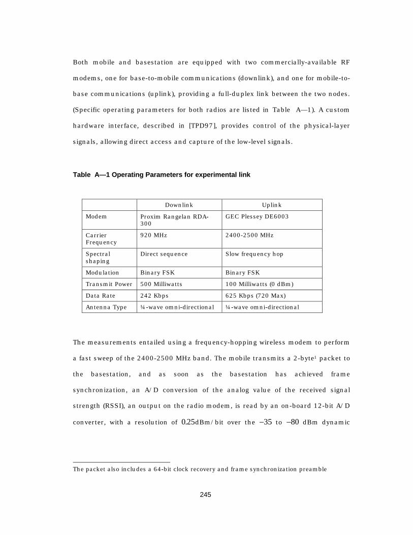
245
Both mobile and basestation are equipped with two commercially-available RF
modems, one for base-to-mobile communications (downlink), and one for mobile-to-
base communications (uplink), providing a full-duplex link between the two nodes.
(Specific operating parameters for both radios are listed in Table A— 1). A custom
hardware interface, described in [TPD97], provides control of the physical-layer
signals, allowing direct access and capture of the low-level signals.
Table A— 1 Operating Parameters for experimental link
Downlink Uplink
Modem Proxim Rangelan RDA-300
GEC Plessey DE6003
CarrierFrequency
920 MHz 2400-2500 MHz
Spectralshaping
Direct sequence Slow frequency hop
Modulation Binary FSK Binary FSK
Transmit Power 500 Milliwatts 100 Milliwatts (0 dBm)
Data Rate 242 Kbps 625 Kbps (720 Max)
Antenna Type ¼ -wave omni-directional ¼ -wave omni-directional
The measurements entailed using a frequency-hopping wireless modem to perform
a fast sweep of the 2400-2500 MHz band. The mobile transmits a 2-byte1 packet to
the basestation, and as soon as the basestation has achieved frame
synchronization, an A/D conversion of the analog value of the received signal
strength (RSSI), an output on the radio modem, is read by an on-board 12-bit A/D
converter, with a resolution of 0 25. dBm/bit over the - 35 to - 80 dBm dynamic
The packet also includes a 64-bit clock recovery and frame synchronization preamble

246
range of the receiver. The RSSI value is then time-stamped and logged to a
workstation via a high-speed wired connection. The frequency is advanced to the
next sequential channel, modulo 100, and the measurement is repeated. In this
fashion, a time-frequency trace file is logged over the desired interval. A single
measurement and frequency change requires approximately 500 m -seconds.
Three measurements were conducted within a 15-meter by 10-meter space, with a
3.5-meter ceiling, and basestation antenna suspended from ceiling in at one end of
the room. As shown in Fig. A— 1, clothed partitions (1.5 meters high) divide the
room, so that, depending on the mobile’s position, the line-of-sight path between
basestation and mobile is blocked. In this work, the goal was to capture time
dynamics that would be typical of an actual user — one who would be giving little
thought to position relative to the basestation, or how body orientation would
impact signal quality. For this reason, we gathered the measurements as the device
was in actual use: the pen-based, notebook-sized portable device is typically
cradled in the forearm of the users non-writing hand. Hence, the device is held
close to the body, about waist level, so that in addition to external shadowing
objects (e.g., partitions), the users body is a significant factor in shadowing the line-
of-sight path between transmitter and receiver.

247
basestation
clothedpartitions(exteriorpartitionsmounted on walls)
A
B
C
doorway
Fig. A— 1. Measurement Environment – Path of user moves continuously through thepoints A-B-C
Two considerations arise in this measurement setup. First, with the overhead of the
software handshake, the current system requires approximately 50 ms to sweep
the entire band. This means that transitions in the frequency response that occur
on a faster timescale are sub-sampled. A second consideration is that the mea-
surement captures only the magnitude response of the channel, and ignores the
phase response. However, for the purposes of predicting signal quality, the informa-
tion we are seeking is when the channel is slowly varying (e.g., when the user is
seated and working, as opposed to walking and using the device), and for how long
it typically remains stationary, rather than trying to capture the precise impulse
response at each instant in time. Further, for practical systems using software-
based control algorithms, 50 milliseconds is a reasonable round-trip update rate
for a measurement-based protocol.
248
A.3 Results of Measurements
Intuitively, one would expect periods of activity followed by periods of stationarity,
corresponding to users’ actual movement patterns. So, with this intuitive under-
standing of what was expected, the first step was to get a feel for how fast the
frequency response changed with time, and what the shape of the frequency
response looked like during times of motion, compared to times when neither the
user or interferers were noticeably moving. To this end, measurements were taken
under the following two conditions:
A.3.1 Stationary Environment
To establish a baseline, this data set was collected with the transmitter and
receiver separated by approximately 3 meters, with a direct line-of-sight path
between the two antennas., with no moving interferers and a stationary user (point
A in Fig. A— 1).The measurements were logged for approximately 20 minutes, where
the position of the portable was shifted by about 1 meter during the measurements
(at approximately 3.5 minutes). This repositioning served as a reference point for
visually characterizing the impact of locally repositioning the mobile, and can be
seen as the peak in Figure A— 2.
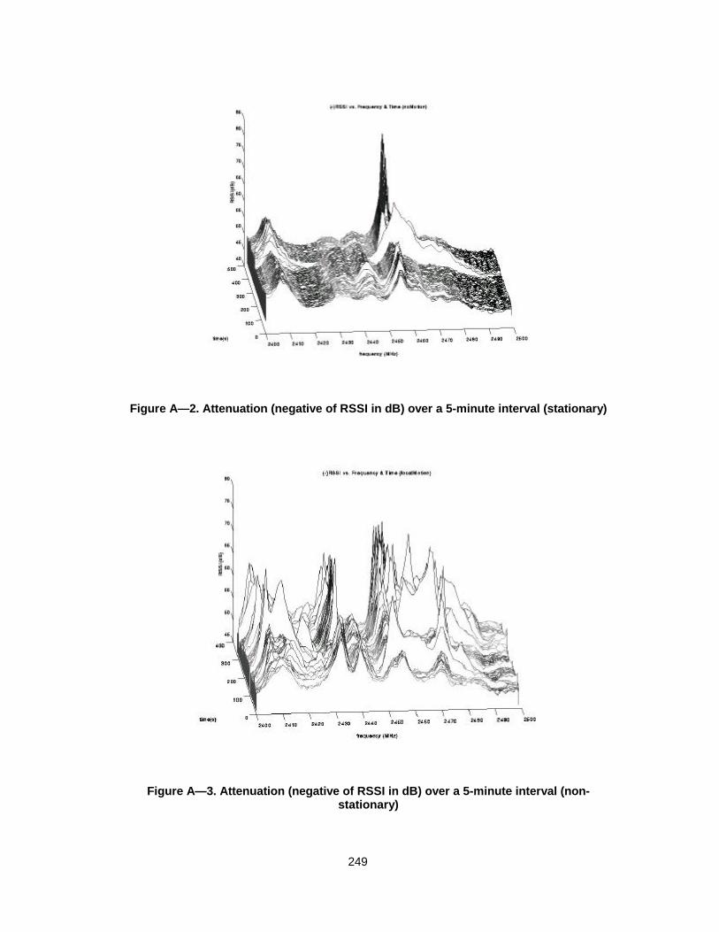
249
Figure A— 2. Attenuation (negative of RSSI in dB) over a 5-minute interval (stationary)
Figure A— 3. Attenuation (negative of RSSI in dB) over a 5-minute interval (non-stationary)
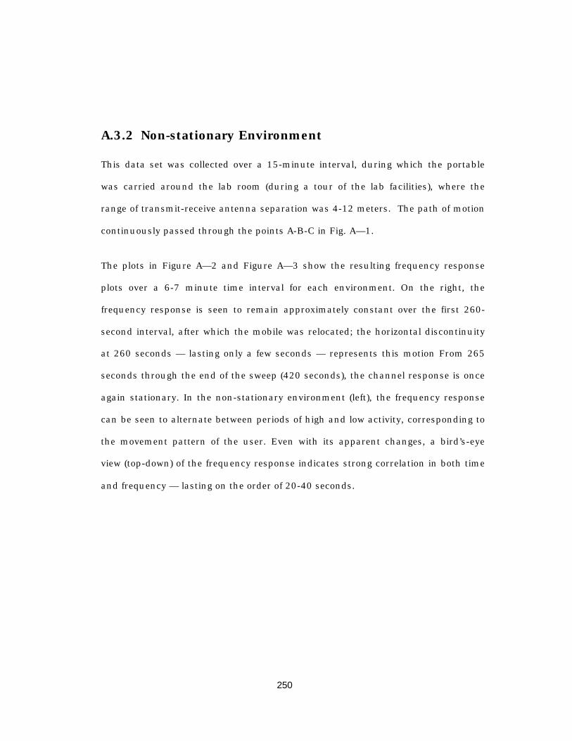
250
A.3.2 Non-stationary Environment
This data set was collected over a 15-minute interval, during which the portable
was carried around the lab room (during a tour of the lab facilities), where the
range of transmit-receive antenna separation was 4-12 meters. The path of motion
continuously passed through the points A-B-C in Fig. A— 1.
The plots in Figure A— 2 and Figure A— 3 show the resulting frequency response
plots over a 6-7 minute time interval for each environment. On the right, the
frequency response is seen to remain approximately constant over the first 260-
second interval, after which the mobile was relocated; the horizontal discontinuity
at 260 seconds — lasting only a few seconds — represents this motion From 265
seconds through the end of the sweep (420 seconds), the channel response is once
again stationary. In the non-stationary environment (left), the frequency response
can be seen to alternate between periods of high and low activity, corresponding to
the movement pattern of the user. Even with its apparent changes, a bird’s-eye
view (top-down) of the frequency response indicates strong correlation in both time
and frequency — lasting on the order of 20-40 seconds.
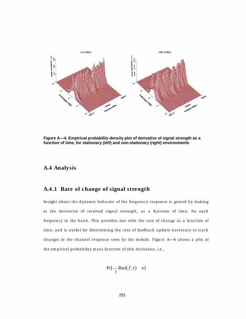
251
no motion with motion
Figure A— 4. Empirical probability density plot of derivative of signal strength as afunction of time, for stationary (left) and non-stationary (right) environments
A.4 Analysis
A.4.1 Rate of change of signal strength
Insight about the dynamic behavior of the frequency response is gained by looking
at the derivative of received signal strength, as a function of time, for each
frequency in the band. This provides one with the rate of change as a function of
time, and is useful for determining the rate of feedback update necessary to track
changes in the channel response seen by the mobile. Figure A— 4 shows a plot of
the empirical probability mass function of this derivative, i.e.,
Pr[ ( , ) ]∂∂ =t
Rssi f t x
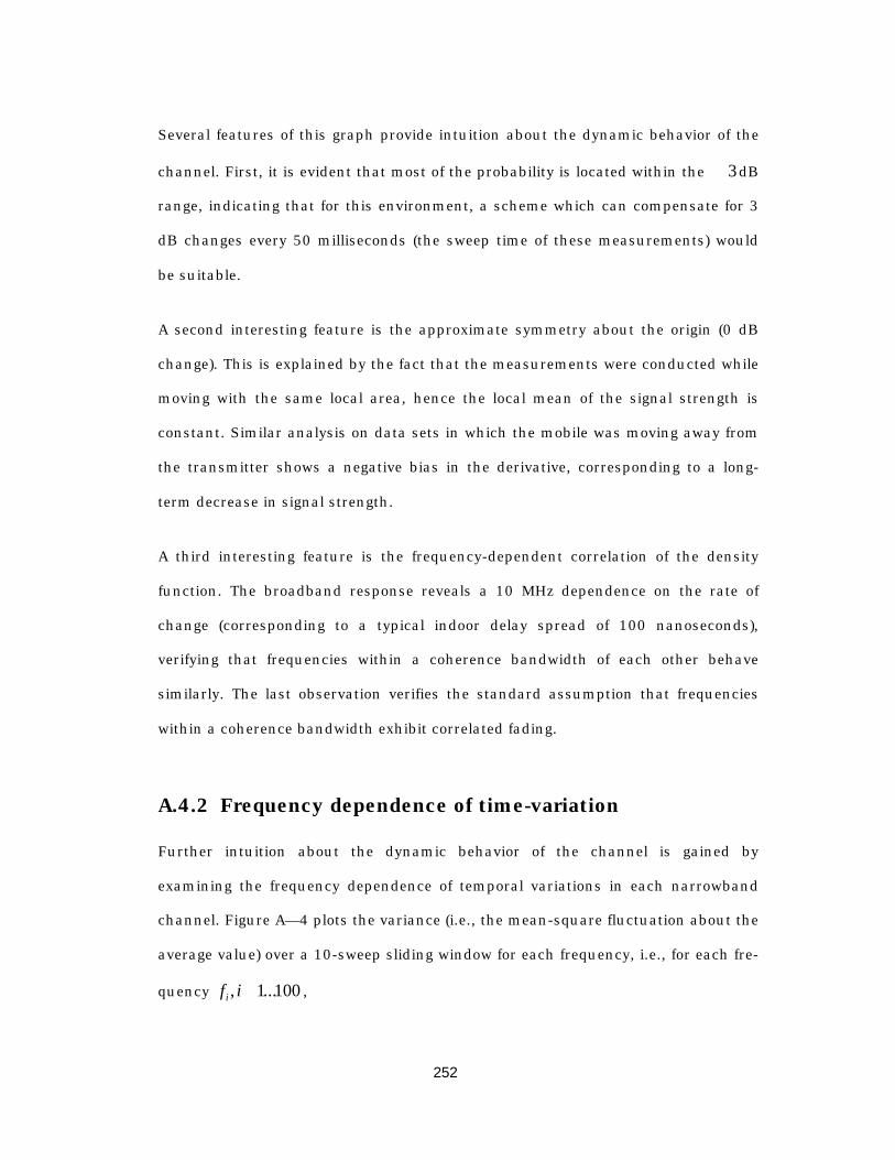
252
Several features of this graph provide intuition about the dynamic behavior of the
channel. First, it is evident that most of the probability is located within the ±3dB
range, indicating that for this environment, a scheme which can compensate for 3
dB changes every 50 milliseconds (the sweep time of these measurements) would
be suitable.
A second interesting feature is the approximate symmetry about the origin (0 dB
change). This is explained by the fact that the measurements were conducted while
moving with the same local area, hence the local mean of the signal strength is
constant. Similar analysis on data sets in which the mobile was moving away from
the transmitter shows a negative bias in the derivative, corresponding to a long-
term decrease in signal strength.
A third interesting feature is the frequency-dependent correlation of the density
function. The broadband response reveals a 10 MHz dependence on the rate of
change (corresponding to a typical indoor delay spread of 100 nanoseconds),
verifying that frequencies within a coherence bandwidth of each other behave
similarly. The last observation verifies the standard assumption that frequencies
within a coherence bandwidth exhibit correlated fading.
A.4.2 Frequency dependence of time-variation
Further intuition about the dynamic behavior of the channel is gained by
examining the frequency dependence of temporal variations in each narrowband
channel. Figure A— 4 plots the variance (i.e., the mean-square fluctuation about the
average value) over a 10-sweep sliding window for each frequency, i.e., for each fre-
quency f ii , ...Œ1 100 ,
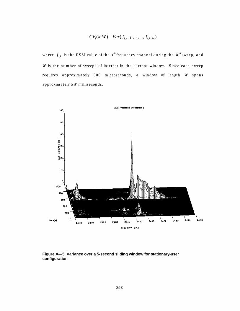
253
CV k W Var f f fi i k i k i k W( ; ) ( , ,..., ), , ,= + +1
where fi k, is the RSSI value of the ith frequency channel during the k th sweep, and
W is the number of sweeps of interest in the current window. Since each sweep
requires approximately 500 microseconds, a window of length W spans
approximately 5W milliseconds.
Figure A— 5. Variance over a 5-second sliding window for stationary-userconfiguration
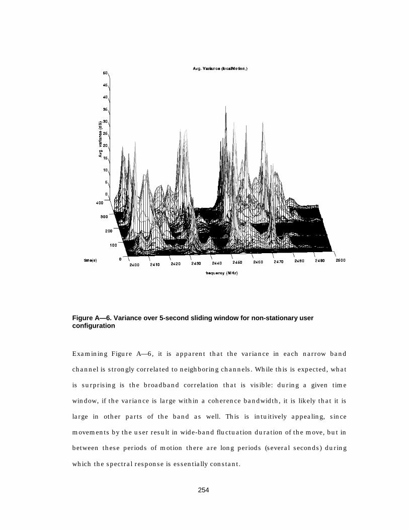
254
Figure A— 6. Variance over 5-second sliding window for non-stationary userconfiguration
Examining Figure A— 6, it is apparent that the variance in each narrow band
channel is strongly correlated to neighboring channels. While this is expected, what
is surprising is the broadband correlation that is visible: during a given time
window, if the variance is large within a coherence bandwidth, it is likely that it is
large in other parts of the band as well. This is intuitively appealing, since
movements by the user result in wide-band fluctuation duration of the move, but in
between these periods of motion there are long periods (several seconds) during
which the spectral response is essentially constant.
255
This information can be used to determine when an adaptive algorithm should
cease to adapt, since if the signal strength is wildly fluctuating in one part of the
band, it is likely that much of the band is affected. For the purposes of an adaptive
protocol, such as the frequency hopping schemes described in [PR94] and [Yun95],
it would be difficult to converge during these periods, but during the periods of
stationarity one expect that an adaptive algorithm would converge and enhance
performance. Depending on the ability of the network to exchange parameters with
the mobile (such as hopping patterns) it is possible that during these periods of
non-stationarity the adaptation should be either temporarily suspended, or the
channel response should be averaged.
This raises the question: what time scale is adequate for updating the feedback
algorithm? An interesting quantity to evaluate is the maximum difference in the
signal strength over a specified time interval. That is, for a signal strength
measurement fi k, at the ith frequency during sweep k , the quantity
D Max f f f Min f f fi k i k i k i k W i k i k i k W, , , , , , ,[ ( , , , ) ( , , , )]= -+ + + +1 1K K
is evaluated.
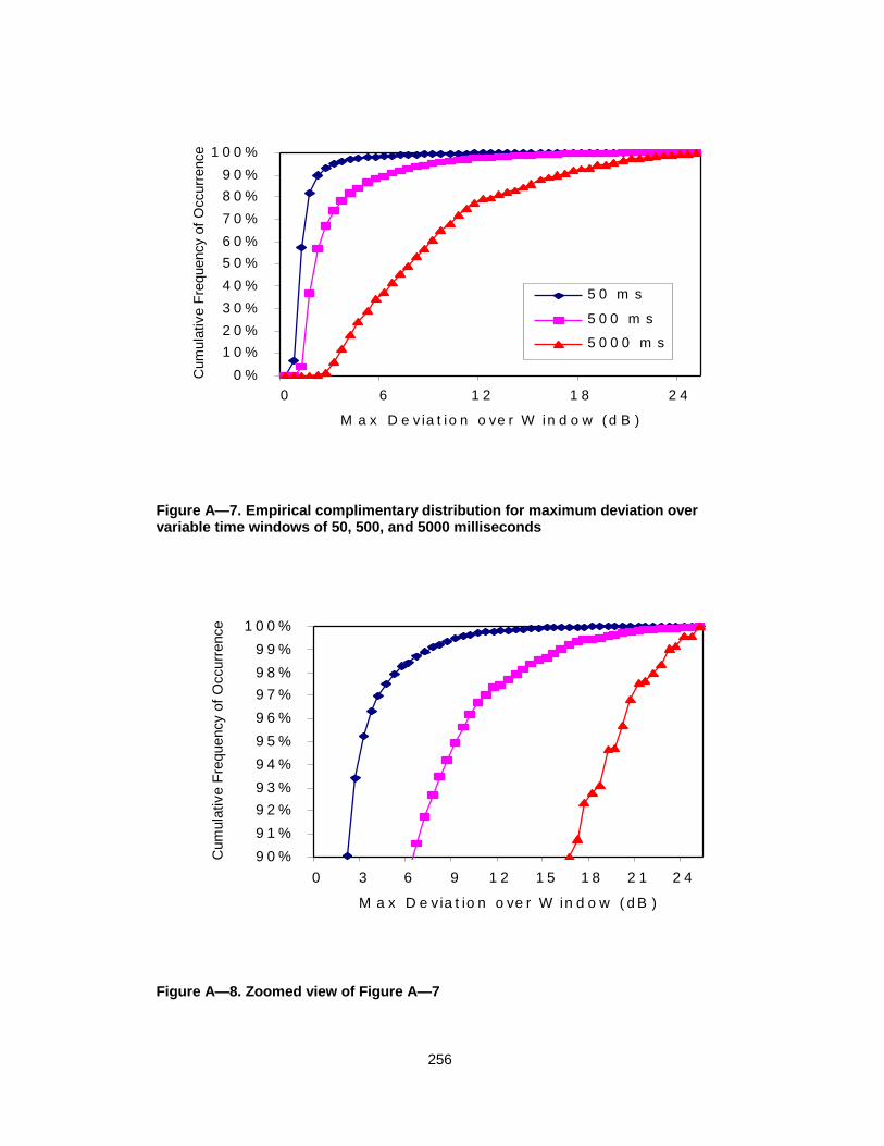
256
0 %
1 0 %2 0 %
3 0 %
4 0 %
5 0 %6 0 %
7 0 %
8 0 %9 0 %
1 0 0 %
0 6 1 2 1 8 2 4
M a x D e via t io n o ve r W in d o w (d B )
Cum
ulat
ive
Freq
uenc
y of
Occ
urre
nce
5 0 m s
5 0 0 m s
5 0 0 0 m s
Figure A— 7. Empirical complimentary distribution for maximum deviation overvariable time windows of 50, 500, and 5000 milliseconds
9 0 %
9 1 %
9 2 %9 3 %
9 4 %
9 5 %
9 6 %
9 7 %9 8 %
9 9 %
1 0 0 %
0 3 6 9 1 2 1 5 1 8 2 1 2 4
M a x D e via t io n o ve r W in d o w ( d B )
Cum
ulat
ive
Freq
uenc
y of
Occ
urre
nce
Figure A— 8. Zoomed view of Figure A— 7
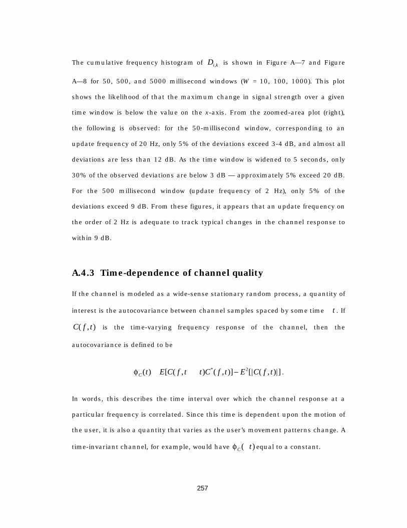
257
The cumulative frequency histogram of Di k, is shown in Figure A— 7 and Figure
A— 8 for 50, 500, and 5000 millisecond windows (W = 10, 100, 1000). This plot
shows the likelihood of that the maximum change in signal strength over a given
time window is below the value on the x-axis. From the zoomed-area plot (right),
the following is observed: for the 50-millisecond window, corresponding to an
update frequency of 20 Hz, only 5% of the deviations exceed 3-4 dB, and almost all
deviations are less than 12 dB. As the time window is widened to 5 seconds, only
30% of the observed deviations are below 3 dB — approximately 5% exceed 20 dB.
For the 500 millisecond window (update frequency of 2 Hz), only 5% of the
deviations exceed 9 dB. From these figures, it appears that an update frequency on
the order of 2 Hz is adequate to track typical changes in the channel response to
within 9 dB.
A.4.3 Time-dependence of channel quality
If the channel is modeled as a wide-sense stationary random process, a quantity of
interest is the autocovariance between channel samples spaced by some time Dt . If
C f t( , ) is the time-varying frequency response of the channel, then the
autocovariance is defined to be
fC t E C f t t C f t E C f t( ) [ ( , ) ( , )] [| ( , )|]*= + -D 2 .
In words, this describes the time interval over which the channel response at a
particular frequency is correlated. Since this time is dependent upon the motion of
the user, it is also a quantity that varies as the user’s movement patterns change. A
time-invariant channel, for example, would have fC t( )D equal to a constant.
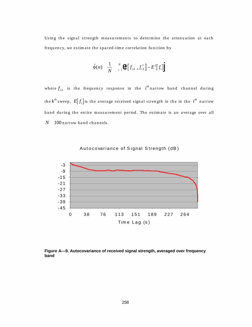
258
Using the signal strength measurements to determine the attenuation at each
frequency, we estimate the spaced-time correlation function by
$( ) , ,*f n
NE f f E fi k n i k ii
N= -+=Â1 21e j
where fi k, is the frequency response in the ith narrow band channel during
the k th sweep, E fi is the average received signal strength in the in the ith narrow
band during the entire measurement period. The estimate is an average over all
N =100 narrow band channels.
A u t o c o va r i ance o f S igna l S t reng th (dB )
-45-39-33-27-21-15
-9-3
0 3 8 7 6 1 1 3 1 5 1 1 8 9 2 2 7 2 6 4
Tim e L a g (s )
Figure A— 9. Autocovariance of received signal strength, averaged over frequencyband
259
Figure A— 9 plots the resulting values for increasing time lag. The plot shows that
the correlation drops of almost linearly (in dB) until approximately 60 seconds of
lag, then remains essentially constant until 200 seconds before dropping off again.
After 300 seconds, the correlation is essentially zero.
A.5 Conclusion
In order to provide variable quality of service to mobile users in an integrated
services network that utilizes a wireless link, the service disciplines on the
backbone network must be able to adapt to handle time-variations in the capacity
of the wireless link. Without an understanding of how fast the channel response
varies with time, it is difficult to design a feedback-based adaptation scheme that is
both effective and efficient: too much feedback wastes bandwidth, while too little
feedback inadequately tracks changes in the channel. The measurements and
analysis presented indicate that for typical changes in signal strength to within 9
dB, a rate of 2 Hz is adequate for the feedback loop. Increasing the sampling rate to
20 Hz allows the changes to be tracked within 3 dB.
260
Append i x B
F i n i t e - s t a t e m o d e l f o rm o b i l i t y p r o t o c o l s i n
In f oPad
B.1 State transition diagrams for InfoNet/InfoPad protocols
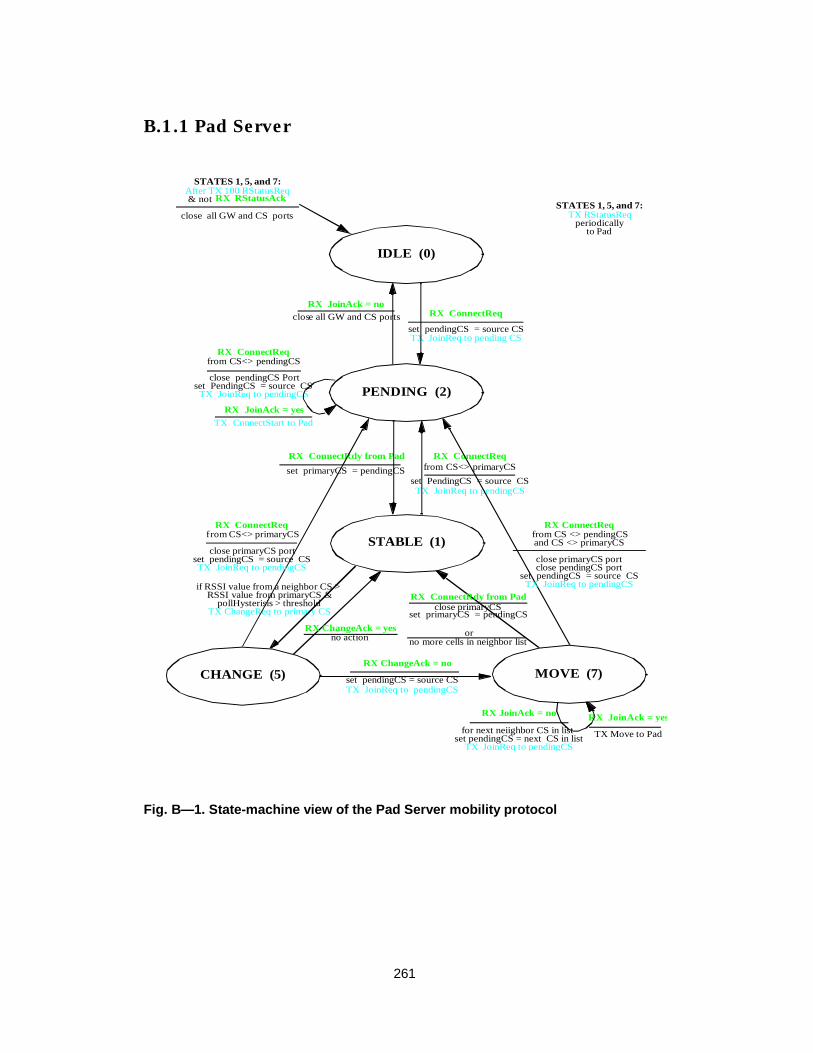
261
B.1.1 Pad Server
RX ConnectReq
set pendingCS = source CSTX JoinReq to pending CS
RX JoinAck = yesTX ConnectStart to Pad
RX ConnectReqfrom CS<> pendingCS
set PendingCS = source CSTX JoinReq to pendingCS
After TX 100 RStatusReq& not RX RStatusAck
close pendingCS Port
close all GW and CS ports
if RSSI value from a neighbor CS > RSSI value from primaryCS &
TX ChangeReq to primary CS
RX ChangeAck = no
set pendingCS = source CSTX JoinReq to pendingCS
set pendingCS = next CS in listTX JoinReq to pendingCS
for next neiighbor CS in list
RX ConnectReqfrom CS<> primaryCS
set PendingCS = source CSTX JoinReq to pendingCS
pollHysterisis > threshold
RX ConnectRdy from Pad
set primaryCS = pendingCS
RX JoinAck = yes
TX Move to Pad
RX ConnectReq
TX RStatusReqperiodically
to Pad
RX JoinAck = no
RX ConnectReqf rom CS<> primaryCS
set pendingCS = source CSTX JoinReq to pendingCS
from CS <> pendingCSand CS <> primaryCS
set pendingCS = source CSTX JoinReq to pendingCS
close primaryCS portclose primaryCS portclose pendingCS port
RX ChangeAck = yesno action
RX JoinAck = noclose all GW and CS ports
RX ConnectRdy from Pad
set primaryCS = pendingCSclose primaryCS
orno more cells in neighbor list
STATES 1, 5, and 7:
STATES 1, 5, and 7:
IDLE (0)
PENDING (2)
STABLE (1)
CHANGE (5) MOVE (7)
Fig. B— 1. State-machine view of the Pad Server mobility protocol

262
B.1.2 Basestation
INIT (0)TX Channel_Req
IDLE (1)
CONNECT_REQ
CONNECT_STARTTX Connect_Start CONNECT_RDY
Packets to Pad are italic
MOVETX Move_Req
CONNECT_DONE
TX Announce
JOIN_ACK
upch = 0, dnch = 0
ChannelAck
exec
ChannelAck
upch = 0dnch = startFreqIndx + offset
JoinAck and upch = 0
ConnectReqand JoinAck
dnch = startFreqIndx + offsetupch = 0
ConnectReq
ConnectStart
ConnectStart
channels set by JoinAck
connectRdytimeout
ConnectRdy
channels set by ConnectStart
ConnectRdy
ConnectRdy
RStatusReq Move
Move
TX Announce
and rStatusReqtimeoutconnectRdy
timeout
to IDLE
start connectRdy timer
connectRdy timer active
stop connectRdy timer
start connectRdy timer
stop connectRdy timer
connectRdy timer active
stop connectRdy timer
stop rStatusAck timer
restart rStatusReq timer
stop rStatusReq timer
BARMMobility FSM
start connectStart timer
stop connectStart timer
connectStart timer active
connectStarttimeout
stop connectStart timer
rStatusReqtimeout
stop rStatusReq timer
to IDLE
start rStatusReq timerRStatusReq
restart rStatusReq timer
ConnectRdystop connectRdy timerstart rStatusReq timer
rStatusReq timer active rStatusReq timer active(4)
(5)
(6)
(7)
(2)
(3)
DisconnectReq in any statecauses transition to idle.
to IDLE
ConnectReqand JoinAckand upch != 0
and upch != 0
or (ConnectStartand upch = 0)
and RStatusReq
Move
or Move timeoutDisconnectReq
TX RStatusReq
TX RStatusReq
All timers are stopped.
start Move timer
stop Move timer
Move timer active
Figure B— 2. Basestation Mobility Finite State Machine

263
B.1.3 Mobile Client
INIT (0)
IDLE (1)
CONNECT_RDY
SCAN_RSSI
MOVE (5)
TX Connect_Req
RSTATUS_ACK
upch = 0
exec
dnch = scan, upch = 0ConnectStart
channels from ConnStart
RStatusReqrStatusReq
ConnectStart
upch/dnch = primary channels
upch = primary upch
channels from Move pkt
start rStatusReq timer
rStatusReq timer active
start heartbeat timer
heartbeat timer active
timeout
TX Connect_Rdy
RStatusReq
Moveand RStatusReq
Move
or Move pkt
dnch = next scan
stop heartbeat timer
stop rStatusReq timer
rStatusReq timer activestop rStatusReq timer
rStatusReq timer active
restart rStatusReq timer
rStatusReq timer active
stop loopRSSI timer
start heartbeat timerMove
(2)
(3)
(4)
TX RStatusAck
and rStatusReqtimeout TX RStatusAck
and RStatusReq
start heartbeat timer
restart rStatusReq timerstart loopRSSI timer
channel scan finished
restart loopRSSI timersw itch downlink channel
last channel scanned
loopRSSI timer active
Figure B— 3. Mobility state machine for mobile client
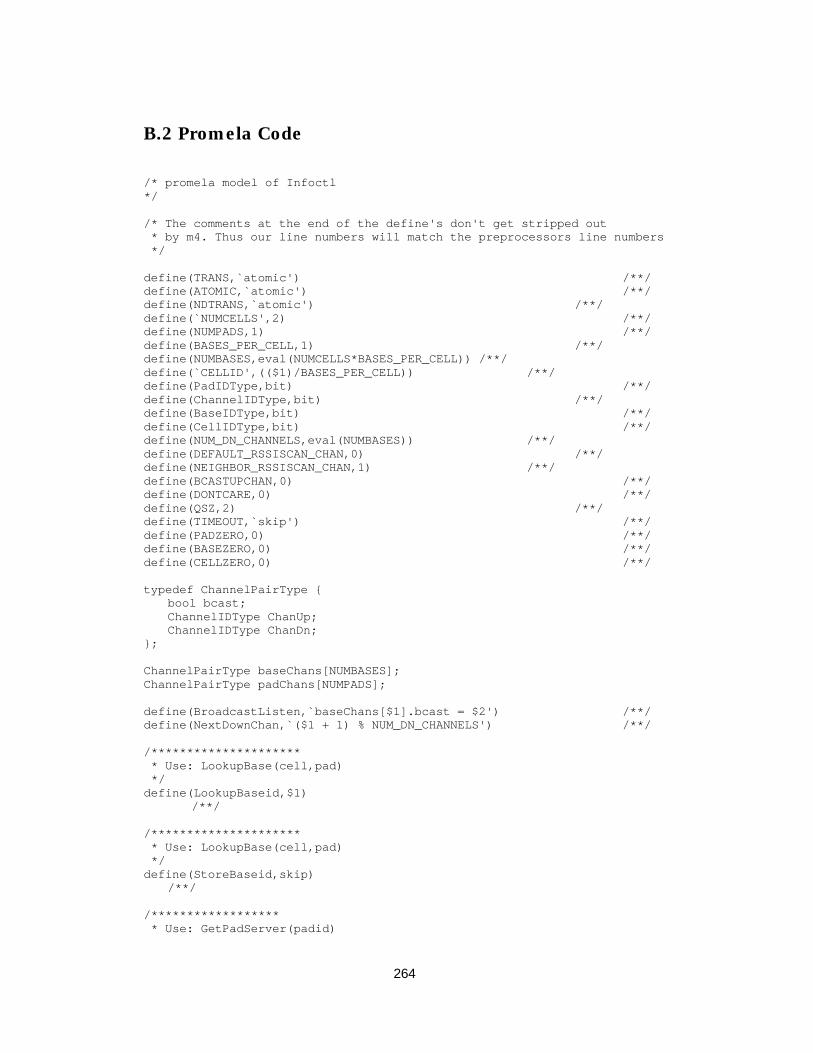
264
B.2 Promela Code
/* promela model of Infoctl*/
/* The comments at the end of the define's don't get stripped out * by m4. Thus our line numbers will match the preprocessors line numbers */
define(TRANS,`atomic') /**/define(ATOMIC,`atomic') /**/define(NDTRANS,`atomic') /**/define(`NUMCELLS',2) /**/define(NUMPADS,1) /**/define(BASES_PER_CELL,1) /**/define(NUMBASES,eval(NUMCELLS*BASES_PER_CELL)) /**/define(`CELLID',(($1)/BASES_PER_CELL)) /**/define(PadIDType,bit) /**/define(ChannelIDType,bit) /**/define(BaseIDType,bit) /**/define(CellIDType,bit) /**/define(NUM_DN_CHANNELS,eval(NUMBASES)) /**/define(DEFAULT_RSSISCAN_CHAN,0) /**/define(NEIGHBOR_RSSISCAN_CHAN,1) /**/define(BCASTUPCHAN,0) /**/define(DONTCARE,0) /**/define(QSZ,2) /**/define(TIMEOUT,`skip') /**/define(PADZERO,0) /**/define(BASEZERO,0) /**/define(CELLZERO,0) /**/
typedef ChannelPairType {bool bcast;ChannelIDType ChanUp;ChannelIDType ChanDn;
};
ChannelPairType baseChans[NUMBASES];ChannelPairType padChans[NUMPADS];
define(BroadcastListen,`baseChans[$1].bcast = $2') /**/define(NextDownChan,`($1 + 1) % NUM_DN_CHANNELS') /**/
/********************* * Use: LookupBase(cell,pad) */define(LookupBaseid,$1)
/**/
/********************* * Use: LookupBase(cell,pad) */define(StoreBaseid,skip)
/**/
/****************** * Use: GetPadServer(padid)

265
*/define(GetPadServer,$1)
/**/
/********************* * Use:GetBestNeighborCell(primaryCS,myPadID) */define(GetBestNeighborCell,(($1 + 1) % NUMCELLS)) /**/
mtype {ConnectReq,BCJoinAck,DisconnectReq,ConnectStart,ConnectResume,RStatusReq, RStatusAck,MovePkt,ConnectReady,Announce,ChangeReq,ChangeAck,JoinReq,PSDirected JoinReq,JoinAck,BC_IDLE,BC_CONNECT_REQ,BC_CONNECT_START,BC_CONNECT_RDY,BC_CONNECT_DONE,BC_MOVE,BC_JOIN_ACK,PC_IDLE,PC_CONNECT_RDY,PC_RSTATUS_ACK,PC_SCAN_RSSI,PS_IDLE,PS_PENDING,PS_STABLE,PS_MOVE,PS_CHANGE};
show chan cellSrvToPadSrv[NUMPADS] = [3] of {mtype,CellIDType,bit};
show chan baseToPadSrv[NUMBASES] = [1] of {mtype,PadIDType,bit};show chan cellSrvToBase[NUMBASES] = [0] of {mtype,PadIDType};show chan padSrvToBase[NUMBASES] = [0] of
{mtype,PadIDType,BaseIDType /* only used in move */};show chan padSrvToCellSrv[NUMCELLS] = [0] of
{mtype,PadIDType};show chan baseToCellSrv[NUMBASES] = [0] of {mtype,PadIDType,bit};
show chan uplinkChan[NUMBASES] = [1] of {mtype,PadIDType};show chan dnlinkChan[NUMBASES] = [1] of {mtype,PadIDType,bit};
define(UplinkWaiting,`(nempty(uplinkChan[0]) || nempty(uplinkChan[1]))')/**/define(DnlinkWaiting,`(nempty(dnlinkChan[0]) || nempty(dnlinkChan[1]))')/**/define(WaitTxFinish,`do :: skip od unless { empty(`$1') }')
/**/
/* * Messages: * to cellServer - ConnectReq(baseid,padid) */
proctype BaseControl(BaseIDType baseid; chan radioUp,radioDn,cellSrvIn,cellSrvOut, padSrvIn,padSrvOut)
{show mtype state = BC_IDLE;PadIDType padID,tmpid;BaseIDType moveID;bool rxJoinAck;show bool statusReqSent;PadIDType ConnectStartPending[NUMPADS];PadIDType ConnectReadySent[NUMPADS];xs radioDn;
define(DO_BC_RESET,`rxJoinAck = false; state = BC_IDLE;BroadcastListen(baseid,true);') /**/

266
define(PadListening,`(baseChans[baseid].ChanDn ==padChans[PADZERO].ChanDn)') /**/define(PadNotListening,`(baseChans[baseid].ChanDn !=padChans[PADZERO].ChanDn)') /**/define(BC_SendPktDn,`if :: PadListening() -> radioDn!`$1'; ::PadNotListening() -> skip; fi;') /**/
reset:atomic {
DO_BC_RESET();statusReqSent = false;tmpid = 0;do:: tmpid < NUMPADS ->
ConnectStartPending[tmpid] = false;ConnectReadySent[tmpid] = false;tmpid++
:: else -> break;od
}
end:do/******************//* IDLE *//******************/:: (state == BC_IDLE) ->
if :: radioUp?ConnectReq(padID) ->
if::(!ConnectStartPending[padID]) ->
ConnectStartPending[padID] = true; cellSrvOut!ConnectReq(baseid,padID);
state = BC_CONNECT_REQ;:: else -> skip;fi
:: cellSrvIn?DisconnectReq(_) ->goto reset;
:: cellSrvIn?BCJoinAck(padID) ->TRANS {rxJoinAck = false;BroadcastListen(baseid,false);
state = BC_JOIN_ACK; }
:: (rxJoinAck == true) -> /* got a BCJoinAc k in some other state */TRANS {rxJoinAck = false;BroadcastListen(baseid,false);state = BC_JOIN_ACK;}
:: timeout ->{{ BC_SendPktDn(Announce(DONTCARE,baseid)) } unless
{nempty(radioDn)} }; fi
/******************//* CONNECT_REQ *//******************/
:: (state == BC_CONNECT_REQ) ->
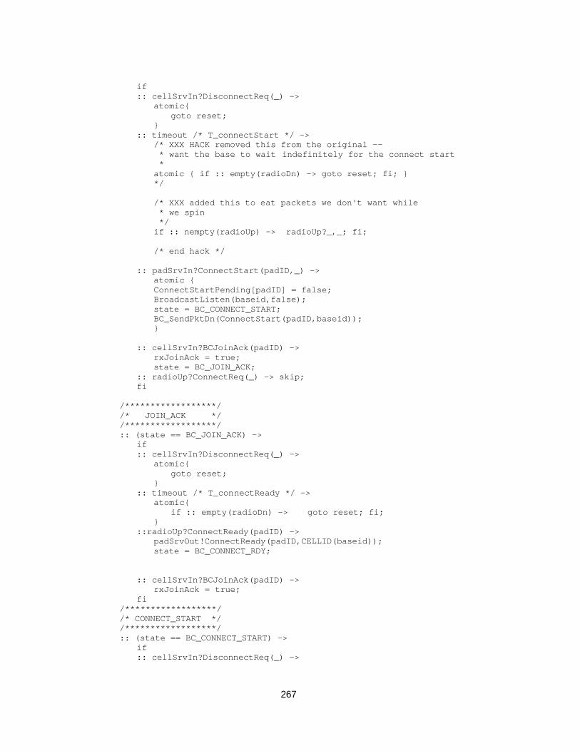
267
if:: cellSrvIn?DisconnectReq(_) ->
atomic{goto reset;
}:: timeout /* T_connectStart */ ->
/* XXX HACK removed this from the original -- * want the base to wait indefinitely for the connect start *atomic { if :: empty(radioDn) -> goto reset; fi; }*/
/* XXX added this to eat packets we don't want while * we spin */if :: nempty(radioUp) -> radioUp?_,_; fi;
/* end hack */
:: padSrvIn?ConnectStart(padID,_) ->atomic {ConnectStartPending[padID] = false;BroadcastListen(baseid,false);state = BC_CONNECT_START;BC_SendPktDn(ConnectStart(padID,baseid));}
:: cellSrvIn?BCJoinAck(padID) ->rxJoinAck = true;state = BC_JOIN_ACK;
:: radioUp?ConnectReq(_) -> skip;fi
/******************//* JOIN_ACK *//******************/:: (state == BC_JOIN_ACK) ->
if:: cellSrvIn?DisconnectReq(_) ->
atomic{goto reset;
}:: timeout /* T_connectReady */ ->
atomic{if :: empty(radioDn) -> goto reset; fi;
}::radioUp?ConnectReady(padID) ->
padSrvOut!ConnectReady(padID,CELLID(baseid));state = BC_CONNECT_RDY;
:: cellSrvIn?BCJoinAck(padID) ->rxJoinAck = true;
fi/******************//* CONNECT_START *//******************/:: (state == BC_CONNECT_START) ->
if:: cellSrvIn?DisconnectReq(_) ->
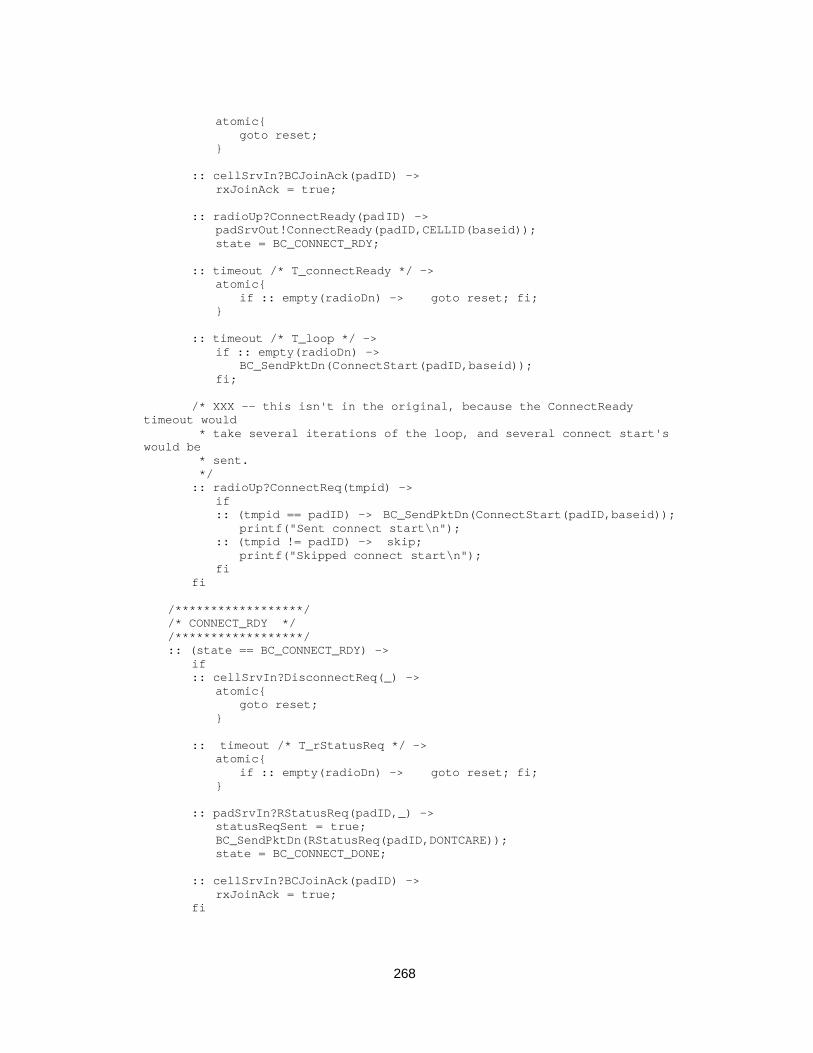
268
atomic{goto reset;
}
:: cellSrvIn?BCJoinAck(padID) ->rxJoinAck = true;
:: radioUp?ConnectReady(padID) ->padSrvOut!ConnectReady(padID,CELLID(baseid));state = BC_CONNECT_RDY;
:: timeout /* T_connectReady */ ->atomic{
if :: empty(radioDn) -> goto reset; fi;}
:: timeout /* T_loop */ ->if :: empty(radioDn) ->
BC_SendPktDn(ConnectStart(padID,baseid));fi;
/* XXX -- this isn't in the original, because the ConnectReadytimeout would
* take several iterations of the loop, and several connect start'swould be * sent.
*/:: radioUp?ConnectReq(tmpid) ->
if:: (tmpid == padID) -> BC_SendPktDn(ConnectStart(padID,baseid));
printf("Sent connect start\n");:: (tmpid != padID) -> skip;
printf("Skipped connect start\n");fi
fi
/******************//* CONNECT_RDY *//******************/:: (state == BC_CONNECT_RDY) ->
if:: cellSrvIn?DisconnectReq(_) ->
atomic{goto reset;
}
:: timeout /* T_rStatusReq */ ->atomic{
if :: empty(radioDn) -> goto reset; fi;}
:: padSrvIn?RStatusReq(padID,_) ->statusReqSent = true;BC_SendPktDn(RStatusReq(padID,DONTCARE));state = BC_CONNECT_DONE;
:: cellSrvIn?BCJoinAck(padID) ->rxJoinAck = true;
fi

269
/******************//* CONNECT_DONE *//******************/:: (state == BC_CONNECT_DONE) ->
if:: cellSrvIn?DisconnectReq(_) ->
atomic{goto reset;
}
:: padSrvIn?MovePkt(padID,moveID) ->state = BC_MOVE;
:: padSrvIn?RStatusReq(padID,_) ->statusReqSent = true;BC_SendPktDn(RStatusReq(padID,DONTCARE));
/* XXX BUG -- skipped this case in the orig */:: radioUp?ConnectReq(tmpid) ->
if:: tmpid == padID ->
BC_SendPktDn(ConnectResume(padID,baseid));:: else -> skipfi
:: radioUp?RStatusAck(padID) ->statusReqSent = false;padSrvOut!RStatusAck(padID,DONTCARE);
:: statusReqSent && timeout /* T_rStatusReq */ ->atomic{
if:: empty(radioDn) -> goto reset;fi;
}
:: timeout /* T_loop */ ->if:: empty(radioDn) -> BC_SendPktDn(Announce(DONTCARE,baseid));fi;
fi
/******************//* MOVE *//******************/:: (state == BC_MOVE) ->
if:: cellSrvIn?DisconnectReq(_) ->
atomic{goto reset;
}:: timeout /* T_move */ ->
atomic{if :: empty(radioDn) ->
goto reset;fi;}
:: timeout /* T_loop */ ->if:: empty(radioDn) ->
270
BC_SendPktDn(MovePkt(padID,moveID));fi;
:: cellSrvIn?BCJoinAck(padID) ->rxJoinAck = true;
fiod
}
proctype PadSrv(PadIDType myPadID; chan fromCellSrv){
show mtype state = PS_IDLE;mtype msg;PadIDType tmpPadID;show CellIDType pendingCS,tmpCS,primaryCS;bool bOk;bit val;
end:do:: (state == PS_IDLE) ->
if:: fromCellSrv?msg(pendingCS,val) ->ATOMIC {
if:: (msg == ConnectReq) ->
padSrvToCellSrv[pendingCS]!JoinReq(myPadID);state = PS_PENDING;bOk = false;
:: else -> skip;fi
}fi
:: (state == PS_PENDING) ->if:: timeout ->
/* XXX this is changed from the original*/padSrvToCellSrv[pendingCS]!DisconnectReq(myPadID);state = PS_IDLE;
:: fromCellSrv?JoinAck(tmpCS,bOk) ->ATOMIC {assert(tmpCS == pendingCS);if:: (tmpCS == pendingCS) && (bOk == true) ->
padSrvToBase[LookupBaseid(pendingCS,myPadID)]!ConnectStart(myPadID,DONTCARE);
state = PS_PENDING;
:: (tmpCS == pendingCS) && (bOk == false) ->state = PS_IDLE;
fi}
::baseToPadSrv[LookupBaseid(pendingCS,myPadID)]?ConnectReady(tmpPadID,tmpCS)->
271
atomic {if:: myPadID == tmpPadID ->
primaryCS = pendingCS;state = PS_STABLE;
padSrvToBase[LookupBaseid(primaryCS,myPadID)]!RStatusReq(myPadID,DONTCARE);
fi;}
fi
:: (state == PS_STABLE) ->if:: timeout /* T_rStatusReq */ ->
padSrvToBase[LookupBaseid(primaryCS,myPadID)]!RStatusReq(myPadID,DONTCARE);
::baseToPadSrv[LookupBaseid(primaryCS,myPadID)]?RStatusAck(tmpPadID,_) ->
ATOMIC {if:: true /* don't change power level */ ->
skip;:: true /* do change power level */ ->
padSrvToCellSrv[primaryCS]!ChangeReq(myPadID);state = PS_CHANGE;
fi}
:: fromCellSrv?ConnectReq(tmpCS,_) ->ATOMIC {TRANS {
if:: (tmpCS == primaryCS) ->
pendingCS = tmpCS;state = PS_PENDING;
:: else -> skip;fi
}}
fi:: (state == PS_CHANGE) ->
if:: fromCellSrv?ConnectReq(tmpCS,_) ->
ATOMIC {if:: (pendingCS == tmpCS) ->
padSrvToCellSrv[pendingCS]!JoinReq(myPadID);:: else -> skip;fi}
:: fromCellSrv?ChangeAck(tmpCS,bOk) ->ATOMIC {if:: (bOk == true) ->
state = PS_STABLE;:: else ->
pendingCS = GetBestNeighborCell(primaryCS,myPadID);state = PS_MOVE;
272
padSrvToCellSrv[pendingCS]!PSDirectedJoinReq(myPadID);fi}
fi:: (state == PS_MOVE) ->
if:: baseToPadSrv[LookupBaseid(pendingCS,myPadID) ]?ConnectReady,tmpCS -
>ATOMIC {assert(tmpCS == pendingCS);padSrvToCellSrv[primaryCS]!DisconnectReq(myPadID);primaryCS = pendingCS;state = PS_STABLE;}
:: fromCellSrv?JoinAck(tmpCS,bOk) ->ATOMIC {TRANS{
assert(bOk == true);assert(tmpCS == pendingCS);
}/* send a move packet via our current base */
padSrvToBase[LookupBaseid(primaryCS,myPadID)]!MovePkt(myPadID,LookupBaseid(pendingCS,myPadID));
}
:: fromCellSrv?ConnectReq(tmpCS,_) ->ATOMIC {if:: (tmpCS != pendingCS && tmpCS != primaryCS) ->
padSrvToCellSrv[primaryCS]!DisconnectReq(myPadID);padSrvToCellSrv[pendingCS]!DisconnectReq(myPadID);pendingCS = tmpCS;padSrvToCellSrv[pendingCS]!PSDirectedJoinReq(myPadID);state = PS_PENDING;
:: else ->skip;
fi}
fiod
}
proctype Cell(CellIDType cellID; chan fromPadSrv,fromBS,toBS){
PadIDType padID;BaseIDType baseid;
end:do:: fromPadSrv?ChangeReq(padID) ->
if::true ->
cellSrvToPadSrv[padID]!ChangeAck(cellID,true);::true ->
cellSrvToPadSrv[padID]!ChangeAck(cellID,false);fi
:: fromBS?ConnectReq(baseid,padID) ->ATOMIC {
273
StoreBaseid(cellID,baseid,padID);cellSrvToPadSrv[padID]!ConnectReq(cellID,DONTCARE);}
:: fromPadSrv?DisconnectReq(padID) ->cellSrvToBase[LookupBaseid(cellID,padID)]!DisconnectReq(padID);
:: fromPadSrv?JoinReq(padID) ->goto allowJoin;
:: fromPadSrv?PSDirectedJoinReq(padID) ->ATOMIC {/* non-deterministically decide if we can allocate this */if:: true ->
/* accept the join request and notify padsrv and base */allowJoin:
cellSrvToPadSrv[padID]!JoinAck(cellID,true);/*** BUG
cellSrvToBase[LookupBaseid(cellID,padID)]!BCJoinAck(padID);*/
:: true ->/* deny the join request */cellSrvToPadSrv[padID]!JoinAck(cellID,false);
fi}
od}
/* * Model for the pad. * * Because the model is too complex to verify in spin using a separatemedia process, * I rewrote the original model (which had a single uplink and downlink) to * explicitly handle two radio channels. * * Modeling hacks: * 1) Make the pad wait if the network is processing a request -- Promelahas no * way to distinguish extremely fast events from slow events. */proctype Pad(PadIDType myid){
show mtype state = PC_IDLE;ChannelIDType scanend;show BaseIDType baseid;BaseIDType tmpbaseid;PadIDType id;chan uplink0 = uplinkChan[0];chan uplink1 = uplinkChan[1];
/** * Definitions and local macros */
define(BroadcastUse,`padChans[$1].bcast = $2') /**/
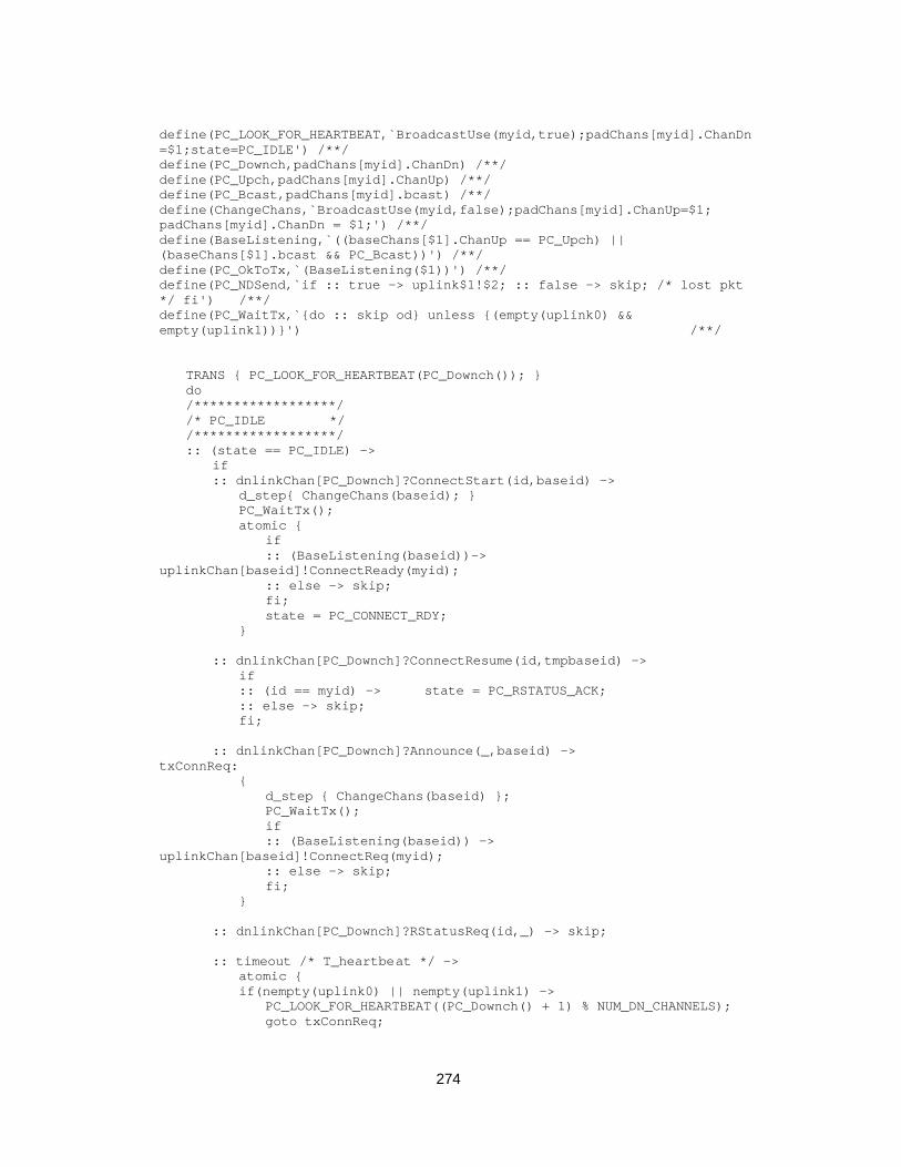
274
define(PC_LOOK_FOR_HEARTBEAT,`BroadcastUse(myid,true);padChans[myid].ChanDn=$1;state=PC_IDLE') /**/define(PC_Downch,padChans[myid].ChanDn) /**/define(PC_Upch,padChans[myid].ChanUp) /**/define(PC_Bcast,padChans[myid].bcast) /**/define(ChangeChans,`BroadcastUse(myid,false);padChans[myid].ChanUp=$1;padChans[myid].ChanDn = $1;') /**/define(BaseListening,`((baseChans[$1].ChanUp == PC_Upch) ||(baseChans[$1].bcast && PC_Bcast))') /**/define(PC_OkToTx,`(BaseListening($1))') /**/define(PC_NDSend,`if :: true -> uplink$1!$2; :: false -> skip; /* lost pkt*/ fi') /**/define(PC_WaitTx,`{do :: skip od} unless {(empty(uplink0) &&empty(uplink1))}') /**/
TRANS { PC_LOOK_FOR_HEARTBEAT(PC_Downch()); }do/******************//* PC_IDLE *//******************/:: (state == PC_IDLE) ->
if:: dnlinkChan[PC_Downch]?ConnectStart(id,baseid) ->
d_step{ ChangeChans(baseid); }PC_WaitTx();atomic {
if:: (BaseListening(baseid))->
uplinkChan[baseid]!ConnectReady(myid);:: else -> skip;fi;state = PC_CONNECT_RDY;
}
:: dnlinkChan[PC_Downch]?ConnectResume(id,tmpbaseid) ->if:: (id == myid) -> state = PC_RSTATUS_ACK;:: else -> skip;fi;
:: dnlinkChan[PC_Downch]?Announce(_,baseid) ->txConnReq:
{d_step { ChangeChans(baseid) };PC_WaitTx();if:: (BaseListening(baseid)) ->
uplinkChan[baseid]!ConnectReq(myid);:: else -> skip;fi;
}
:: dnlinkChan[PC_Downch]?RStatusReq(id,_) -> skip;
:: timeout /* T_heartbeat */ ->atomic {if(nempty(uplink0) || nempty(uplink1) ->
PC_LOOK_FOR_HEARTBEAT((PC_Downch() + 1) % NUM_DN_CHANNELS);goto txConnReq;
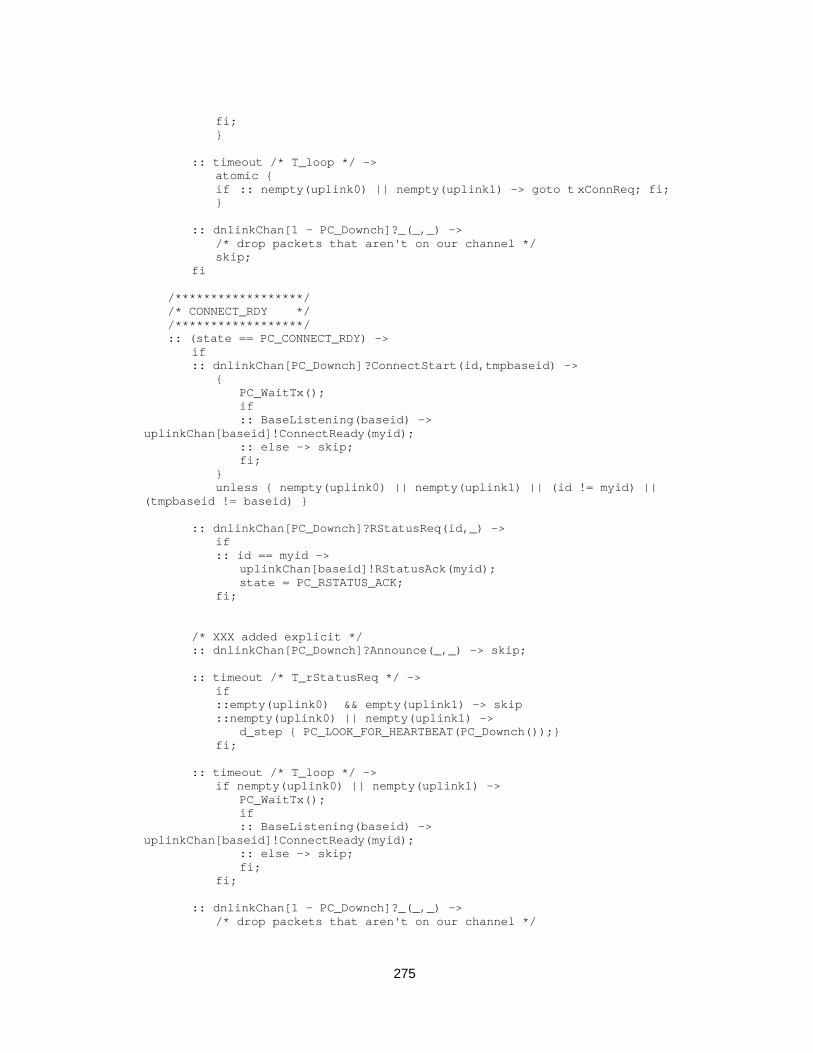
275
fi;}
:: timeout /* T_loop */ ->atomic {if :: nempty(uplink0) || nempty(uplink1) -> goto t xConnReq; fi;}
:: dnlinkChan[1 - PC_Downch]?_(_,_) ->/* drop packets that aren't on our channel */skip;
fi
/******************//* CONNECT_RDY *//******************/:: (state == PC_CONNECT_RDY) ->
if:: dnlinkChan[PC_Downch]?ConnectStart(id,tmpbaseid) ->
{PC_WaitTx();if:: BaseListening(baseid) ->
uplinkChan[baseid]!ConnectReady(myid);:: else -> skip;fi;
}unless { nempty(uplink0) || nempty(uplink1) || (id != myid) ||
(tmpbaseid != baseid) }
:: dnlinkChan[PC_Downch]?RStatusReq(id,_) ->if:: id == myid ->
uplinkChan[baseid]!RStatusAck(myid);state = PC_RSTATUS_ACK;
fi;
/* XXX added explicit */:: dnlinkChan[PC_Downch]?Announce(_,_) -> skip;
:: timeout /* T_rStatusReq */ ->if::empty(uplink0) && empty(uplink1) -> skip::nempty(uplink0) || nempty(uplink1) ->
d_step { PC_LOOK_FOR_HEARTBEAT(PC_Downch());}fi;
:: timeout /* T_loop */ ->if nempty(uplink0) || nempty(uplink1) ->
PC_WaitTx();if:: BaseListening(baseid) ->
uplinkChan[baseid]!ConnectReady(myid);:: else -> skip;fi;
fi;
:: dnlinkChan[1 - PC_Downch]?_(_,_) ->/* drop packets that aren't on our channel */

276
skip;fi
/******************//* RSTATUS_ACK *//******************/:: (state == PC_RSTATUS_ACK) ->
progress_RStatusAck:if/* XXX added explicit */:: dnlinkChan[PC_Downch]?Announce(_,_) -> skip;
:: dnlinkChan[PC_Downch]?MovePkt(id,tmpbaseid) ->if:: (id == myid) ->
if:: true -> /* we change */
d_step{baseid = tmpbaseid;ChangeChans(baseid);}{
PC_WaitTx();if:: BaseListening(baseid) ->
uplinkChan[baseid]!ConnectReady(myid);:: else -> skip;fi;
} unless { nempty(dnlinkChan[PC_Downch]) };:: true -> /* we stay, waiting for move threshold */
skip;fi
:: else -> /* packet not for me */skip;
fi
:: dnlinkChan[PC_Downch]?RStatusReq(id,_) ->if:: (id == myid) ->
PC_WaitTx();if:: BaseListening(baseid) ->
uplinkChan[baseid]!RStatusAck(myid);:: else -> skip;fi;skip; /* needed for the d_step -- the break above in the
PC_Send macro causes grief */TRANS {scanend = PC_Downch();PC_Downch = NextDownChan(PC_Downch());state = PC_SCAN_RSSI;}
:: else -> /* packet not for me */skip;
fi:: timeout /* T_rStatusReq */ ->
TRANS {PC_LOOK_FOR_HEARTBEAT(PC_Downch());}
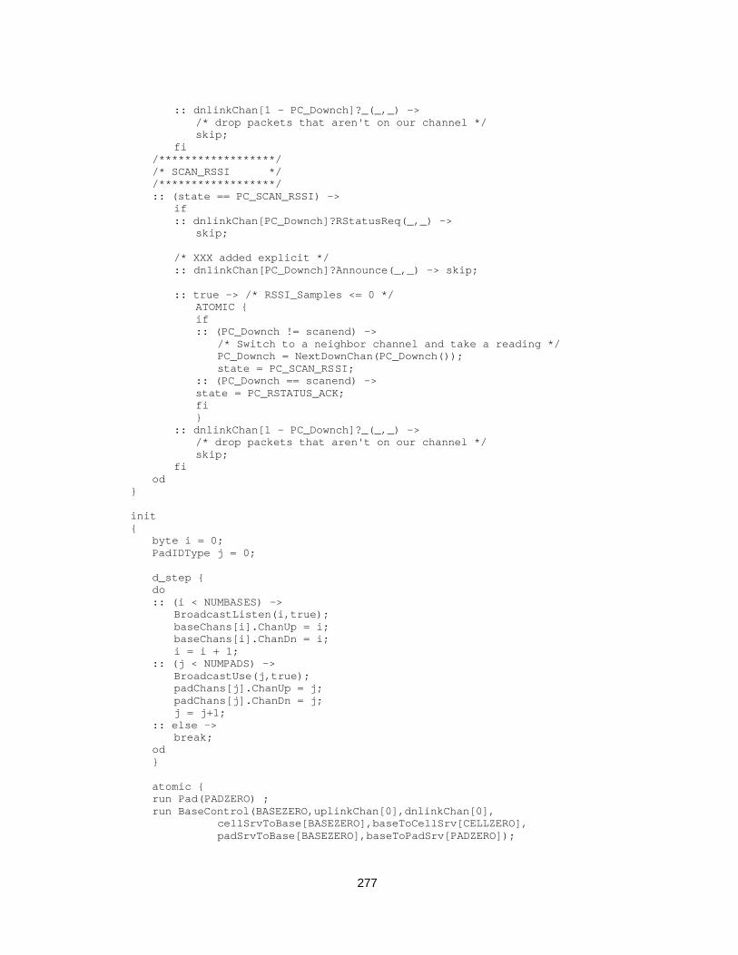
277
:: dnlinkChan[1 - PC_Downch]?_(_,_) ->/* drop packets that aren't on our channel */skip;
fi/******************//* SCAN_RSSI *//******************/:: (state == PC_SCAN_RSSI) ->
if:: dnlinkChan[PC_Downch]?RStatusReq(_,_) ->
skip;
/* XXX added explicit */:: dnlinkChan[PC_Downch]?Announce(_,_) -> skip;
:: true -> /* RSSI_Samples <= 0 */ATOMIC {if:: (PC_Downch != scanend) ->
/* Switch to a neighbor channel and take a reading */PC_Downch = NextDownChan(PC_Downch());state = PC_SCAN_RSSI;
:: (PC_Downch == scanend) ->state = PC_RSTATUS_ACK;fi}
:: dnlinkChan[1 - PC_Downch]?_(_,_) ->/* drop packets that aren't on our channel */skip;
fiod
}
init{ byte i = 0; PadIDType j = 0;
d_step {do:: (i < NUMBASES) ->
BroadcastListen(i,true);baseChans[i].ChanUp = i;baseChans[i].ChanDn = i;i = i + 1;
:: (j < NUMPADS) ->BroadcastUse(j,true);padChans[j].ChanUp = j;padChans[j].ChanDn = j;j = j+1;
:: else ->break;
od}
atomic {run Pad(PADZERO) ;run BaseControl(BASEZERO,uplinkChan[0],dnlinkChan[0],
cellSrvToBase[BASEZERO],baseToCellSrv[CELLZERO],padSrvToBase[BASEZERO],baseToPadSrv[PADZERO]);

278
runCell(0,padSrvToCellSrv[CELLZERO],baseToCellSrv[BASEZERO],cellSrvToBase[BASEZERO]) ;
run PadSrv(PADZERO,cellSrvToPadSrv[PADZERO]);run BaseControl(1,uplinkChan[1],dnlinkChan[1],
cellSrvToBase[1],baseToCellSrv[1],padSrvToBase[1],baseToPadSrv[PADZERO]);
run Cell(1,padSrvToCellSrv[1],baseToCellSrv[1],cellSrvToBase[1]) ;}
}
/*Local Variables: ***mode:Fundamental ***tab-width:4 ***End: ****/

279
Append i x C
G lossa ry o f no ta t i onand SDL l egend
C.1 Notation
The following symbols appear in the text (all in Chapter 5) and are standard in
formal languages and automata theory.
Q P¥ Cartesian product of the sets Q and P, that is, the set formed from alltuples ( , )q pi j
x yŸ Logical conjunction of x and y (“x and y”)
x y⁄ Logical disjunction of x and y (“x or y”)
ÿ x Logical complement of x
AB
C
Conditional inference, as in “If A and B hold, then C holds”
Q p|= “Property p holds in the model Q”
280
C.2 SDL graphical legend
The diagrams on the next two pages show most of the symbols of the SDL graphical
language used in the text and in the accompanying files. These diagrams are
intended only to serve as a partial reference to assist in the reading. The fragments
below do not describe a complete SDL system, nor do they describe any meaningful
behavior.

281
Block Interaction_Legend 1(1)
This is a text symbol, usedto hold textual definitions ofdata types, operators, etc.
operator
Block_A
This is a block reference symbol.Blocks are the fundamental unit of lexicalscope and structural hierarcy. They containother blocks and/or processes, procedures, anddata declarations
A process reference symbol. Processes specifydynamic behavior using extended finite state machines.They execute concurrently, communicating by means ofsignals and remote variables
Process_A(1) Process_C
The number of processinstances follows theprocess name. If process instances can be dynamicallycreated, then the first numberindicates the initial instances,and the second number indicatesthe maximum number of instances
Process_B(0,N)
Dynamically created processcan have zero instances atstartup. The dashed arrow showsthe parent/child relationship
OperatorNameProcedureName
These are operator and procedurereference symbols. Operators can be definedaxiomatically or algorithmically
Bidirectional_SignalRoute
Signal6,Signal7
Signal4,Signal5
Unidirectional_SignalRouteSignal1,(Signallist2),Signal3
Fig. C— 1. SDL Block interaction diagram
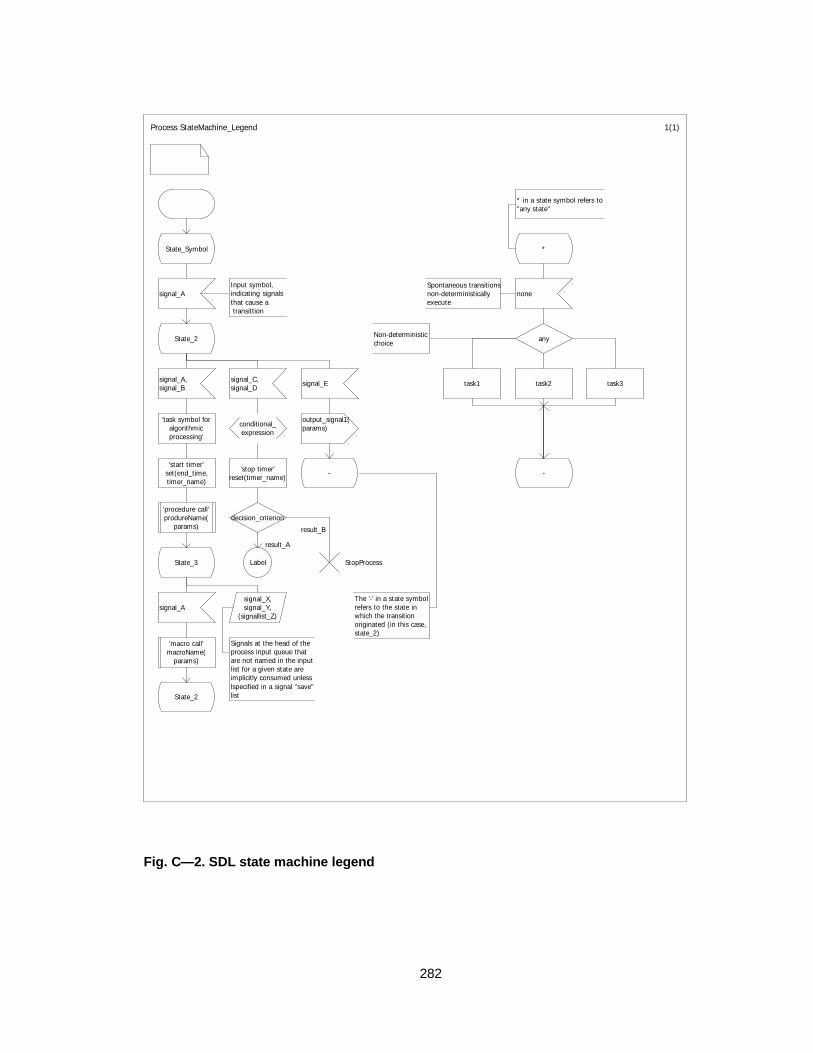
282
Process StateMachine_Legend 1(1)
* in a state symbol refers to"any state"
State_Symbol *
signal_AInput symbol, indicating signalsthat cause a transittion
Spontaneous transitionsnon-deterministicallyexecute
none
State_2 Non-deterministicchoice any
signal_A,signal_B
signal_C,signal_D signal_E task1 task2 task3
'task symbol foralgorithmicprocessing'
conditional_expression
output_signal1(params)
'start timer'set(end_time,timer_name)
'stop timer'reset(timer_name) - -
'procedure call'produreName(
params)decision_criterion
State_3 Label StopProcess
signal_Asignal_X,signal_Y,
(signallist_Z)
The '-' in a state symbolrefers to the state inwhich the transition originated (in this case,state_2)
'macro call'macroName(
params)
Signals at the head of theprocess input queue thatare not named in the inputlist for a given state areimplicitly consumed unlesslspecified in a signal "save"listState_2
result_A
result_B
Fig. C— 2. SDL state machine legend
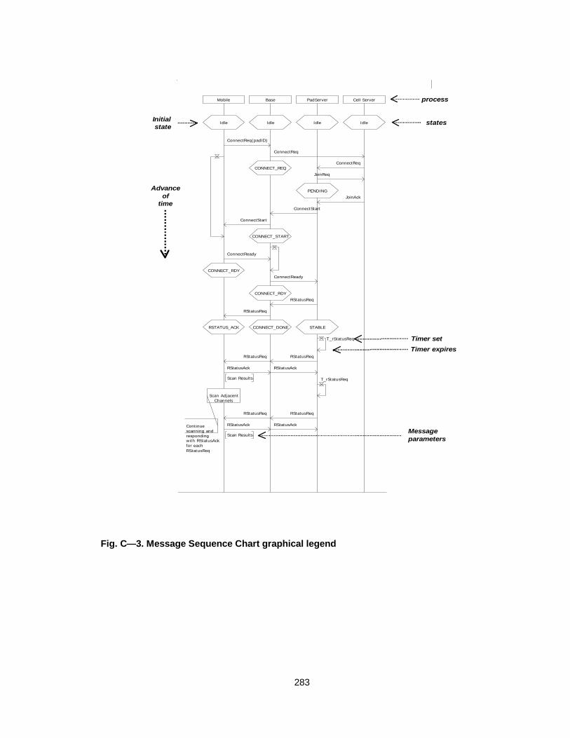
283
Mobile Base PadServer Cell Server
IdleIdleIdleIdle
ConnectReq(padID)
ConnectReq
CONNECT_REQConnectReq
JoinReq
PENDINGJoinAck
ConnectStart
ConnectStart
CONNECT_START
ConnectReady
CONNECT_RDYConnectReady
CONNECT_RDYRStatusReq
RStatusReq
CONNECT_DONERSTATUS_ACK STABLE
T_rStatusReq
RStatusReq RStatusReq
RStatusAckRStatusAck
Scan Results T_rStatusReq
Scan AdjacentChannels
RStatusReqRStatusReq
RStatusAck
Scan Results
RStatusAckContinuescanning andrespondingwith RStatusAckfor each RStatusReq
process
states
Timer set
Timer expires
Messageparameters
Advanceof
time
Initial state
Fig. C— 3. Message Sequence Chart graphical legend