a metallurgical investigation of the bath smelting of
TRANSCRIPT

University of WollongongResearch Online
University of Wollongong Thesis Collection University of Wollongong Thesis Collections
1997
A metallurgical investigation of the bath smelting ofcomposite organic and ferrous wastesStuart John StreetUniversity of Wollongong
Research Online is the open access institutional repository for theUniversity of Wollongong. For further information contact ManagerRepository Services: [email protected].
Recommended CitationStreet, Stuart John, A metallurgical investigation of the bath smelting of composite organic and ferrous wastes, Doctor of Philosophythesis, Department of Materials Engineering, University of Wollongong, 1997. http://ro.uow.edu.au/theses/1479


A Metallurgical Investigation of the Bath Smelting of
Composite Organic and Ferrous Wastes
A thesis submitted in fulfilment of the requirements
for the award of the degree
Doctor of Philosophy
from
University of Wollongong
by
Stuart John Street, B.E (Hons), M.E (Hons)
Department of Materials Engineering
1997

Candidates Certificate
This is to certify that the work presented in this thesis was carried out by the
candidate in the Department of Materials Engineering, University of Wollongong,
and has not been submitted to any other university or institution for a higher
degree.
Stuart Street

"I may not care but that doesn't mean I don't understand."
- Homer.J.Simpson
"The Simpsons"

Acknowledgements
It has been said that:
"Sometimes a scream is better than a thesis"
- Ralph Waldo Emerson (1803-1882)
to all those that heard me scream, thanks.

Abstract
Bath smelting has recently been the focus of several large research and
development programs investigating alternative ironmaking processes.
Fundamental studies have contributed to the understanding of smelting-
reduction processes however these have not been entirely applicable to the
smelting of composite pellets. Recently, bath smelting has also been
evaluated for its potential for processing metallurgical wastes, the driving force
being to develop suitable alternatives to traditional disposal methods such as
dumping in landfills; one such technology is the EnvlRONment process. In
general, many pyrometallurgical waste processes have been developed but
few have been commercialised successfully. It is evident many processes
have suffered economically because of poor understanding and control of
process fundamentals.
Although the EnvlRONment process, which smelts composite organic and
ferrous waste pellets in a single vessel reactor, had been developed to the
pilot plant stage, the mechanisms of smelting-reduction were not fully
understood. Pilot plant trials highlighted critical aspects of the process but did
not provide sufficient information to quantify process fundamentals, clearly
further investigation was warranted.
Smelting, Xray, and thermogravimetric experiments provided foundation for
an in-depth study of reaction kinetics and mechanisms, while also allowing
other relevant issues of waste processing, using bath smelting technology, to
be addressed. Supporting the experimental investigations an extensive heat
transfer model was developed which was used to predict temperature profiles
and smelting times. The bath smelting reactor was modelled in 2 distinct
stages, a falling gas region and an in-slag smelting region, heating was
determined to be controlled by internal resistance.

The general smelting behaviour of composite pellets was observed during
pilot plant and laboratory trials. Smelting of composite pellets, as performed
in the EnvlRONment process, was simulated in the laboratory by smelting
composite pellets in crucibles containing slag at 1500°C; to allow for accurate
experimental interpretation, and to increase the degree of experimental
control, process pellets were replicated by surrogate laboratory pellets with a
simplified number of components. Cellulose was trialled as a surrogate
component for organic waste.
Further experiments were performed using Xray fluoroscopy and radiography
techniques to observe the progress of the smelting-reduction reactions in slag
at 1500°C. Examination of the smelting reaction with the Xray techniques also
allowed observation of the effect of composite smelting on slag foaming.
The kinetics and mechanisms of reduction of composite pellets was
investigated using non-isothermal thermogravimetric techniques to 1200°C.
Thermal analysis via this route was selected because the experimental
techniques are the most suited means to investigate temperature dependant
phenomena of self-reducing systems.
Smelting experiments provided significant fundamental information relevant to
an understanding of smelting reactions in composite smelting. Analysis and
interpretation of the experiments corroborated with the heat transfer model
predictions, which was used together with the thermogravimetric results to
clearly identify reaction mechanisms and explain other process phenomena.
Key process reactions in composite smelting were identified as:
- thermal decomposition of volatiles
- direct reduction and carburisation of iron
- pellet ablation through melting and dissolution

- reduction of dissolved oxides in slag.
Predicted temperature profiles within the composite pellets suggest that much
of the volatile matter is lost during the falling gas region by thermal
decomposition. For the surrogate pellets containing cellulose upto 7 8 % of the
volatile matter is lost during the falling gas region. The heat transfer model
predicted sensible melting times, for a 1.5cm diameter pellet a melting time of
92s was predicted, similar times were observed in smelting trials. An
important finding of the heat transfer work was that although the in-slag
smelting stage w a s based on a fully submerged object experimental
observations show that an immersion crust does not form on the pellet during
its initial contact with the slag bath, and that the composite pellet is not
submerged during smelting.
Thermogravimetry revealed the complexity of internal reduction in iron oxide-
carbon systems when high and low volatility carbon sources contribute
towards reduction. The contribution to reduction from the high volatility carbon
being influenced by heating rate and the presence of secondary non-volatile
material, measured charring levels for cellulose varied between 13 and 2 2 % .
The main steps in the thermogravimetric reaction profiles were attributed to
thermal decomposition of cellulose between 280 and 320°C and stepwise
reduction of hematite above 550°C.
The dominant reduction mechanism in composite bath smelting was identified
as internal reduction within the pellet. Approximately 9 0 % of the total
reduction occurs within the pellet, the extent of which is sufficient that much of
the iron is also carburised before pellet ablation is complete. The other
significant finding of the study was that slag foaming was shown not to be a
critical issue for process control of composite smelting.

C O N T E N T S
Acknowledgements iv
Abstract v
Table of Contents viii
CHAPTER 1 INTRODUCTION 1
CHAPTER 2 STEELWORKS DUST 6
2.1 Introduction. 6
2.2 Origin of Steelworks Dust. 7
2.3 Dust Characterisation. 12
2.4 Considerations for Recycling and Disposal
of Steelworks Dust. 36
2.5 Dust Treatment Technology. 42
2.5.1 Encapsulation. 43
2.5.2 Pyrometallurgical Processes. 48
2.5.3 Hydrometallurgical Processes. 79
2.5.4 Miscellaneous. 83
2.5.5 Summary of Dust Treatment Technologies. 88
CHAPTER 3 BATH SMELTING OF IRON 93
3.1 Introduction. 93
3.2 Thermodynamics of Smelting. 95

3.2.1 Reduction of Oxides. 95
3.2.2 Reduction of Iron Oxides. 103
3.3 Bath Smelting Reactions. 111
3.3.1 Dissolution of Pellets in Bath Smelting. 111
3.3.2 Function of the Slag Layer. 129
3.3.3 Slag Foaming. 132
3.3.4 Reduction of Iron. 147
3.3.5 Function of Carbonaceous Material
in Bath Smelting. 168
3.3.6 Post Combustion. 177
3.4 Bath Smelting Processes. 188
3.4.1 Corex Process. 193
3.4.2 DIOS Process. 197
3.4.3 AISI Process. 200
3.4.4 Hlsmelt Process. 201
3.4.5 LRP/Romelt Process. 205
3.4.6 Miscellaneous Processes. 207
CHAPTER 4 PILOT PLANT TRIAL OF THE BATH SMELTING
OF COMPOSITE W A S T E PELLETS 213
4.1 Introduction. 213
4.2 EnvlRONment Process History 213
4.3 Process Description. 217
4.4 EnvlRONment Process Thermodynamics. 228

4.5 EnvlRONment Process Commercialisation. 230
4.6 100kg D C Arc Furnace Pilot Plant Smelting Trial. 231
4.6.1 Trial Description 233
4.6.2 Carbon Balance 235
4.6.3 Discussion of the Pilot Plant Trial 237
4.6.5 Conclusion 243
CHAPTER 5 Reactor Stoichiometry and Enthalpy Balance
Equations 245
5.1 Introduction 245
5.2 Model Development 245
5.3 Discussion 251
5.4 Conclusion 253
CHAPTER 6 HEAT TRANSFER CONSIDERATIONS 254
6.1 Introduction. 254
6.2 Model Formulation. 269
6.2.1 Modes of Heat Transfer in the
EnvlRONment Process. 269
6.2.2 Heat Flow. 270
6.2.3 Heat Transfer Formulation. 272
6.2.3.1 Falling Gas Region. 272
6.2.3.2 In-Slag Smelting Region. 287
6.3 Discussion. 295
6.4 Conclusion. 325
CHAPTER 7 E N V I R O N M E N T PROCESS COMPOSITE
PELLET CHARACTERISATION. 328
7.1 Introduction. 328
7.2 Characterisation Techniques. 329
7.3 Results and Discussion. 330
7.4 Conclusions. 337
CHAPTER 8 EXPERIMENTAL 346
8.1 Introduction. 346
8.2 Smelting Experiments. 347
8.2.1 Apparatus. 347
8.2.2 Materials. 349
8.2.3 Experimental Procedure. 351
8.3 Xray Fluoroscopy and Radiography Experiments. 362
8.3.1 Apparatus. 362
8.3.2 Materials. 365
8.3.3 Experimental Procedure. 365
8.4 Thermogravimetric Experiments. 368
8.4.1 Apparatus. 368
8.4.2 Materials. 377
8.4.3 Experimental Procedure. 377
CHAPTER 9 RESULTS 382

9.1 Smelting Experiments. 382
9.1.1 Introduction. 382
9.1.2 Smelting Experiment Results. 385
9.2 Xray Fluoroscopy and Radiography Experiments. 391
9.2.1 Introduction. 391
9.2.2 Xray Fluoroscopy and Radiography
Experiment Results 397
9.3 Thermogravimetric Experiments. 402
9.3.1 Introduction. 402
9.3.2 Thermogravimetric Results. 402
CHAPTER 10 DISCUSSION 438
10.1 Bath Smelting of Composite Waste Pellets. 438
10.2 Direct Reduction of Composite Pellets 453
10.3 Evaluation of Bath Smelting Technology for the
Simultaneous Treatment of Steelworks and
Organic Wastes. 476
10.4 Recommendations for Continuing Research 480
CHAPTER 11 CONCLUSIONS 484
REFERENCES
BIBLIOGRAPHY
PUBLICATIONS
APPENDICES

1
Chapter 1 Introduction
The iron and steel industry is undergoing significant restructuring during the
1990's, never before has there been such a need as for the balance between
economic viability and environmental responsibility. The industry because of
its size, and traditional close proximity to suburbia, is viewed with particular
scepticism by society in regards to its protection of the environment.
Lessening the environmental impact of industrial activity is likely to challenge
the industry simply because of the speed that society demands changes to be
made [1]. Compensating this urgency is that the environmental challenge and
the need to satisfy societal concerns are seen as driving forces for technical
revolution [2,3].
A recent survey of the American iron and steel industry is indicative of the
industry world wide [3]. The Sloan Steel Industry Study identified four main
driving forces in the industry:
- reduction in capital costs
- raw material shortages
- environmental concerns
- customer demands.
As a response to remain competitive the iron and steel industry is currently
pursuing new ironmaking technologies in an effort to lessen their
environmental impact and reduce operating and capital costs. Nearly 7 0 % of
the companies surveyed identified new ironmaking technologies as being
critical to achieving long term competitiveness. Of the alternative ironmaking
technologies bath smelting has been the focus of several large research and
development programs worldwide, including Hlsmelt - Australia [4], AISI-DOE

- United States [5], and DIOS - Japan [6]. The incentives for developing bath
smelting processes include high smelting intensities, the ability to use non-
coking coals, low fuel consumption rates, and reduced capital costs [7].
Fundamental studies have made major contributions to the understanding of
smelting-reduction, in particular, the function of the slag layer [8], rate
phenomena [9], and postcombustion [10].
The slag layer in a bath smelting process is complex, being considered the
main reaction medium of the process [11], reactions occurring in the slag layer
include slag foaming, ore dissolution and reduction, and coal devolatilisation.
Excessive slag foaming is a limitation in bath smelting, research being
undertaken to identify foaming mechanisms and means of suppression [12-
15].
Ore reduction is process dependant, in deep slag processes dissolved oxides
are reduced by carbon contained in suspended iron droplets and by char
entrained in the slag. The combined reduction rate of a process being
dependant on the slag weight, the distribution of iron droplets suspended in
the slag, the FeO content of the slag, and the weight of carbonaceous material
in the slag [3,7].
Carbon is vital to bath smelting being not only the reductant but a source of
thermal energy. One of the drivers in development of the new bath smelting
processes is the potential to use cheaper low rank coals, however, use of low
rank coals effects dust generation rates, bath carburisation and
postcombustion. Postcombustion, which is allied to many other process
reactions, has been extensively studied [16,17], its control seen as critical to
achieving low coal consumption rates.
Although considerable fundamental research has seen many processes
developed to demonstration size scale few have been commercialised.

Significantly the Sloan Steel Industry Study found that only 2 0 % of integrated
steel companies had active research programs investigating new ironmaking
technologies, while greater than 6 0 % were investigating the problem of
treating iron and steelmaking dusts [3].
Waste redemption and minimisation have become key areas of development,
potential strategies for the iron and steel industry include increased recycling
and resource management, the use of new technologies, and the fostering of
industrial synergy [18,19].
Recycling to be successful primarily needs to be economically viable, given
the large investment capital required recycling of low value material is often
unattractive [20], unless government regulations force the activity. Although
the infrastructure for recycling of scrap and slag are well developed, those for
ferruginous steelworks dusts are not.
Iron and steelmaking operations generate particulate matter, these dusts
originate from several sources and are found to be complex physical mixtures
of fine particles. Traditionally steelworks dusts have been dumped as landfill
rather than being recycled because although there is an incentive to recover
the resource value of the dusts (iron), zinc and other elements are detrimental
to iron and steelmaking. However, many companies have foreseen the need
for greater recycling, becoming increasingly concerned over the liability of
landfills. Not surprising many iron and steel producers have adopted pro
active environmental policies [21]. The primary factor in determining the fate
of wastes is economic, in general the first strategy in a recycling program is to
utilise empty plant capacity. Recycling iron and steelmaking dusts, or sludges,
through existing plant infrastructures is problematic and often requires
extensive blending [22], for this reason numerous processes have been
developed specifically for treating wastes.

The suitability of a waste treatment system is site dependant, viability being
dependant on waste volume and composition, and local regulations.
Pyrometallurgical processes are most prevalent but increasingly
encapsulation and hydrometallurgical technologies are being investigated,
although numerous processes have been technically demonstrated few have
been commercialised.
Treatment options include material benefication with full or partial resource
recovery, the extent of resource recovery and the process products varies
considerably between technologies. Options for iron recovery in
pyrometallurgical processes are to fully reduce the oxides to produce a pig
iron or metallised pellets, or partial reduction leaving the iron components as
a slag product. Zinc and other volatile metals are typically recovered as
oxides, or in metallic form using a splash condenser.
Bath smelting technologies have been increasingly investigated for their
potential to treat iron and steelmaking wastes, one such technology being the
EnvlRONment process. Of particular interest is the development of bath
smelting processes to treat composite wastes, that is combined feed sourced
from different waste streams. In essence composite smelting is fundamentally
different from that of well known bath smelting processes such as DIOS, AISI-
D O E and Hlsmelt. As an example of composite bath smelting the
EnvlRONment process utilises a single vessel reactor with no prereduction
and no preheating of the feed, while the composite feed contains steelworks
dust, organic waste, supplementary carbon for reduction, and fluxes for slag
making. The other major difference is that process energy is supplied by
electricity rather than through postcombustion. Although the concept of
composite smelting had been evaluated on different scales, including
numerous trials in a 100kg D C arc furnace, the kinetics and mechanisms of
smelting were not fully understood.

An understanding of the mechanisms and kinetics is a keystone to process
optimisation. It is thought that although the fundamentals of smelting-
reduction reactions are now well understood these m a y not be entirely
applicable to the smelting of composites. It is also thought that investigations
of gaseous reduction of iron ore coal composites [23-30] are not totally
applicable because they do not involve liquid phase reactions neither do they
consider reactions using high and low volatile carbonaceous materials
simultaneously. To gain a broad understanding of bath smelting waste
composites it was necessary to study the characteristics of the feed material,
the thermodynamics and heat transfer of the process, and to investigate
smelting-reduction reactions.
The objectives of this study were to chiefly investigate the reduction of self-
reducing composite materials and to use this in conjuction with theoretical
modelling to better understand the process. Previous research on the process
had been limited to evaluation trials and the typical hardware problems
associated with a pilot plant. Reduction and smelting-reduction reactions
were investigated using thermogravimetric, in-slag smelting, and Xray
radiography smelting experiments.

6
Chapter 2 Steelworks Dust.
2.1 Introduction.
The iron and steel industry over the last 25 years has made considerable effort to
address its pollution problem. The shear quantities of raw material and energy that
are consumed by the industry has previously placed a considerable load on the
environment; it is the extent of this impact that society, as it becomes more
environmentally aware, is now questioning. It is clear that the iron and steel industry
faces many challenges in the 1990's [1], the environmental challenge may burden
the industry not so much for the technical difficulties but the speed at which changes
may need to be made. Fruehan [3], like many others, however see's this challenge
as one of the driving forces for technical revolution over the forthcoming decade. A
review by Szekely [2] addresses a broad range of pollution problems that the iron
and steel industry are yet to resolve, in his Yukama Memorial Lecture (1995) Szekely
felt that in a broad sense the industry must address the question "how well it meets
its overall responsibilities to society in terms of its overall environmental
performance." Effective measures to address environmental problems are costly and
often slow to implement and it may be that the best solution requires synergistic
interaction with other industries.
The iron and steel industry is reducing their environmental impact in four ways: i) by
compliance with environmental protection regulations; ii) implementing energy
conservation measures; iii) recycling and resource management; and iv) new
technology development [18]. Typical of the increasing awareness of the need for
balance between environmental protection and healthy industrial economy [31] are
policy statements such as:
British Steel pic [32]; "...promote further recycling of products and by-products ...to
minimise the risk of all forms of pollution of water, air and land,..."

7
and in Australia, B H P Ltd [33]; "...We are committed to ....a high standard of care for
the environment" and "BHP strives for excellence and performance in all its activities,
including safety and environmental management."
Recycling is viewed as a key component of resource management, Derby [34]
forecasts the needs and uses for recyclable material becoming more important,
hypothesising that the driving forces of recycling are; i) economic, ii) resource
scarcity and iii) social. The infrastructure for recycling in many steel plants is well
developed, particularly for in-house scrap and slag. However ferruginous steel works
dusts are not currently recycled to their full potential.
The advent of oxygen steelmaking and the need to comply with ever tightening
policies has resulted in greater amounts of steel works dust being generated and
collected. Derby [34] postulates that socio-economic forces have created a potential
market for recycling wastes such as steel works dusts, arguing that wastes
designated for landfill have no net benefit for society only a potential risk. As society
becomes more environmentally aware the balance between risk and benefit will
become further questioned.
2.2 Origin of Steelworks Dust.
The majority of processes in iron and steelmaking generate fine particulate matter.
Dusts can originate from fuel combustion products, physical degradation of feed
materials and process chemical reactions.
Blast furnace dust is generated when particulate matter is borne up by the ascending
gases and out of the furnace. The off gas stream consisting of entrained ore, burden
material (such as coke fines and sinter) and reaction products. Hay [35]
characterised steelworks dust from the B H P steel plant in Newcastle and found that
the blast furnace dust consisted primarily of fragments of sinter and ore. Similarly

Fosnacht [36] characterised wet and dry collected blast furnace dust from Inland
Steel's Indiana Harbour Works and found that both were multicomponent mixtures of
degraded blast furnace burden.
Dust generation from the blast furnace tends to be irregular due to the pressure
fluctuations that are encountered with normal operations. Typical off gas streams
have a dust loading of 25 to 100g/Nm3 [37] with dust generation rates cited between
6 to 25kg/tonne of metal produced [35,38,39], although occasionally higher rates are
reported, such as those generated by Tata Steel, 35kg/tonne [40].
The high velocity of the off gas stream from the B O S contains suspended particles of
flux, slag and metal [35,38,39]. Typical dust loadings are 100g/Nm3 which relates to
dust being generated at approximately 10kg/tonne of metal [39]. Szekely's [19]
research proposal to study effective means for minimising oxide wastes found that
dust generation rates were dependant on B O S operations, being in the range of 4 -
31kg/t, but typically 18kg/t. Similarly at BHP's Port Kembla plant dust generation
rates were found to be highly variable, but over a weeks operation averaged out at
7.4kg/t [41]. At Inlands Steel's plant the different B O S operations, full combustion
and suppressed off gas hood combustion, resulted in dust generation rates of 24 and
17kg/t respectively [42].
Ellis and Glover [43], studying mechanisms of fume formation in oxygen steelmaking,
ascertained that B O S dust was mainly generated by an explosive dispersion of
ejected droplets by bubbles of carbon monoxide. Ellis and Glover reasoned, based
on the differences in the characteristics and quantity of fume generated by the two
stages in their experiments, that bubble bursting and droplet explosion, rather than
evaporation of iron from droplets, was the main source of dust. A more recent study
of dust formation mechanisms by Nedar et al [44] suggests that of the four dust
forming mechanisms; charging, slag ejection, metal ejection, and vaporisation,
vaporisation at the end of a blow can contribute upto 3 6 % of the total dust load.

9
Electric arc furnace (EAF) dusts are generated similarly to B O S dusts, and typically
represent 1 to 2 % of the charge weight [38,39,45,46]. Szekely [19] however found a
much wider range of dust generation rates, 4 - 32kg/t, with an average of 18kg/t; the
wide range reflecting different operating practise between the surveyed plants. The
amount of EAF dust generated is dependant on process and operating parameters
such as quality of scrap charged, melting rates, degree of oxidation, charging and
blowing practices, and to some extent the gas exhaust system [19,34,38]. During
rapid heating the off gas consists of fine dusts, originating from charging, as well as
vaporised elements, while during melt-boiling the dust will contain significant
quantities of fine metal and slag droplets.
BHP's Rooty Hill mini mill generates EAF dust at a rate of approximately 10kg/t, with
a projected yearly figure approaching 8000tpa [47]. The steel industry in the U.S
generates approximately 450kt(1993) of EAF dusts annually, by the year 2000 it is
projected that this figure will have grown to 850kt [48], while another projection
forecasts 900kt per year by 2003 [34]. Given similar forecasted growth rates for EAF
use in Japan and America [49] it is likely that the Japanese industry will be
generating approximately 750kt per year by 2000. World wide estimates (1991) are
that approximately 4.6 million t/yr of EAF dusts are generated [46], this compares
with B O S dust generation being in excess of 9 million tonnes annually.
Apart from actual furnace operations, iron bearing waste can be generated in
numerous other processes associated with iron and steelmaking, possible sources of
dust in an integrated iron and steelworks are depicted in Figure 1.
For a perspective of the overall waste generated in the production of steel the data
adapted by Szekely [2] is worth reviewing. Table 1 shows that steel compares
favourably to many other metals.

10
| Possible sources of air pollution at integrated works
Coke ovens Iron works
1 Charging Carbonising
1 Quenching By-products
(Smoke) (Smoke)
Crushing, screening
(Dust)
(Smoke, (H,S) dust)
Steel works Ancillaries
Steel-making furnaces
Rolling mills
Ancillaries Mill furnaces
(Dust, fume, (Dust) (Dust) S02)
(SO,)
Blast furnaces
Ore preparation plant
Ore dryers Sinter plant
(Dust) (Dust,S02)
Iron and steel foundries
Locos Boilers
(Dust, S02) (Smoke) (Dust, smoke, S02)
Furnace top
Gas plant
(Dust) (Dust)
Slag disposal
Pig-casting
(Dust. S02) (Dust)
Figure 1. Dust sources in an integrated iron and steelworks [37].

Table 1. Solid waste generated in metal production [2].
Metal
Al
Steel
Cu
Zn
Mg
Ti
ton waste/ton metal
5.5
0.6
139
0.8
5.3
3.5
3 0009 03202992 3

12
2.3 Dust Characterisation.
Numerous studies have all resolved that steelworks dust are complex physical
mixtures of fine particles. Particle size, composition, heterogeneity, and mineralogy
are dependant not only on the process but also the method of collection. Dust
collection methods vary from plant to plant, typically it involves a 2 stage process
where dust is collected as a dry fraction and secondly a wet fraction, the wet fraction
when thickened and dewatered is generally referred to as sludge. Dry dust catching
removes most of the coarse particles in the primary cleaning stage, while wet
scrubbing removes fine and any remaining coarse particles.
The geneity of blast furnace dust particles clearly reflect the nature of their
generation, namely degradation/fragmentation, the loose fines then being carried off
by ascending gases in the blast furnace. Hay [35] characterised dust from BHP's
Newcastle plant and found mainly irregular shaped particles, the particles being
composed entirely, or a heterogeneous mixture, of feed material. Similarly,
Robinson [50] characterised BF dust from BHP's Port Kembla plant, optical
microscopy revealed irregular shaped particles while electron microscopy, at high
magnification, revealed only a few spherical particles. Although contradicting other
results, dust from the Smederevo blast furnace (Yugoslavia) was found to be mainly
spherical [51].
Particle size has been clearly shown to vary with the collection system used and can
vary from less than 1u.m to greater than 100]im [35,39]. Fosnacht [36] investigated
both wet and dry collected dusts and found the main difference was the coarser size
of the dry fraction, varying from 2.4mm to 14^im. The fineness of wet collected dusts
depending largely on the type of equipment used in the primary dry collection stage.
Typical size distributions of blast furnace dusts, both wet and dry are given in Table
2. Dusts from French blast furnace operations were sized by the Institut de
Recherches de la Siderurgie Francaise (IRSID) [52], two different dedusting circuits

13
Table 2. Blast furnace dust particle size distributions.
biZe Wt(%) Wt(%) Wt(%) Wt(%) Wt(%) Wt(%) Wt(%) Wt(%) Wt(%) im) + 150 61.3 _ _ _ _ _ 40 44.9
+ 125 - - 11.1 15
-150 + 45
-125 + 75
-125 + 63
-106 + 75
+ 75
-75 + 53
-75 + 45
-63 +45
+ 53
-53 + 38
-45 + 38
-53 + 43
-45 + 32
-45 + 10
-45
-38
-32
-32 + 20
-18 + 10
-10
dust
Ref.
-
10.5
-
5.4
-
-
0.4
—
—
-
3.4
-
-
dry
40
_
-
-
51.6
15.4
_
-
-
7.0
—
—
_
-
26.0
-
_
-
wet
40
_
24.0
-
-
-
_
10.9
-
-
-
-
_
__
54.0
-
-
_
-
wet
53
17.6
26
14.0
7.4 - 15.6
14.4 19.0 14.7
8.7
0.8
4.5 7.3
----- 17.8
33.1 -
- 55 - - 7.1 -
24
----- 29.5
14.8 _____
22.2 - 30.0 - - 25.3
wet unknown unknown unknown dry wet
54 55 51 56 57 50

14
were used followed by wet collection. It was found that the size distribution of the
wet collected dusts could be suitably described by a R R S D function, as shown in
Figure 2. Although the overall range of particle sizes were similar, the size
distribution of the wet collected dusts was found to vary widely across the plants.
Similarly the chemical composition of blast furnace dusts vary from plant to plant, the
variation due to different feed material, operating practise, and furnace control.
Typical chemical analysis are given in Table 3. Day to day operating fluctuations in a
blast furnace can result in dust composition fluctuations of ± 1 0 % [36], Table 4 shows
typical compositions from 11 blast furnaces studied by IRSID [52]. Similarly Table 5
shows the variations in BF dust compositions monitored over a 10 year period at the
Smederevo plant [51]. The relationship between particle size and composition is
also of interest because of potential dust benefication and recycling. Zinc in BF dust
predominantly exists as a coating on particles, Itoh and Fieser [54] reasoned that
dust particles act as nuclei for vaporised zinc to condense upon. Higher
concentrations of zinc being found on the smaller dust particles due to their larger
relative surface area. While Pazdej and Steiler [52] determined the relationship
between Zn content of the dusts and the initial Zn input to the blast furnace, finding
that the finer the particle size the higher the content, as shown in Figure 3.
In general, the mineralogy of BF dust is difficult to determine. Wet collected dusts
are particularly difficult to characterise due to the particles being very small and often
amorphous. Pazdej and Steiler [52] found that 50-90% of Zn and Pb was present as
oxides, while upto 3 0 % existed as metallics. Many smaller (1-2u.m) free particles
were found to be amorphous, although they were able to identify the presence of
sulphides, silicates and zinc ferrite. Mineralogical characterisation was also found
difficult by Hay [35] who could only clearly identify a single species, ot-Fe304.

15
1
10
36.8
50 60 70
80
90
95
98
99
* ***' s
•
/
/
/
/ / 1
1 /
/ /
20 50 100 250
Part icle size d in pi
Figure 2. Particle size distributions of dust generated by French blast furnace
operations studied by IRSID [52].

16
Table 3. Blast furnace dust chemical compositions (wt%).
^ e total
Fe°
Si02
Al203
CaO
MgO
ZnO
MnO
Na20
K20
PbO
S
C
dust
Ref.
44.7
0.6
5.1
—
4.2
—
0.18
—
—
—
—
0.26
18.8
unknown
38
40.8
0.1
6.1
—
7.4
—
0.06
—
—
—
—
0.14
20.6
unknown
35
34.7
1.1
7.1
—
2.5
—
1.12
—
—
—
—
0.74
37.5
wet
53
37
—
8.1
4.9
3.9
1.2
—
1.2
0.08
0.74
—
—
24
dry
40
35.6
—
9.7
3.5
3.5
1.6
—
trace
0.09
0.45
—
—
26
wet
40
33
—
3.4
—
9.5
—
2.9
0.47
—
—
0.13
—
—
unknown
50
38
—
—
—
—
—
1.6
—
0.13
0.50
—
0.4
19
unknown
56
22.0
—
17.7
0.59
5.9
9.6
21.5
0.25
0.27
0.48
0.22
0.92
39.5
unknown
51
55.7
—
7.1
1.6
8.3
2.4
-
0.14
0.14
1.0
-
0.1
40.9
dry
57
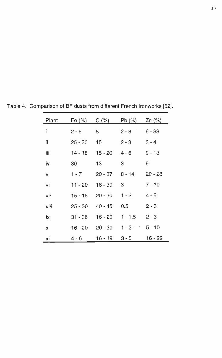
Table 4. Comparison of BF dusts from different French Ironworks [52].
Plant
ii
iii
iv
V
vi
vii
viii
ix
x
xi
Fe (%)
2-5
25-30
14-18
30
1 -7
11-20
15-18
25-30
31 -38
16-20
4-6
C (%)
8
15
15-20
13
20-37
18-30
20-30
40-45
16-20
20-30
16-19
Pb (%)
2-8
2-3
4-6
3
8- 14
3
1 -2
0.5
1-1.5
1 -2 "
3-5
Zn (%)
6-33
3-4
9-13
8
20-28
7-10
4-5
2-3
2-3
5-10
16-22

18
Table 5. Average annual Fe and Zn levels in BF dust generated at Smederevo [51].
Year Fe (%) Zn (%)
1980 19.2 6.3
1981 8.4 49.6
1982 1.3 53.6
1983 43.2 3.1
1984 36.3 7.0
1985 31.9 17.2
1986 28.2 17.2
1987 21.3 2.8
1988 21.2 8.2
1989 13.7 12.5
1990 21.8 17.3

19
% Zn
40-
30-
20-
10-
B A
.© \ \
- • • » \
« \ ':. » X
• •» X .
.• • • . \ ^ w
v •.©••:>..
• i 1 * -
'0 50 100 d'inpm
Figure 3. Relationship between Zn input to blast furnace and Zn content of wet BF
dust. I. Zn input 11 OOg/tonne hot metal. II. Zn input 850g/tonne of hot metal. III. Zn
input 100 - 200g/tonne of hot metal [52].
20
Fosnacht found that the overall mineralogy of dry and wet collected dusts were
similar, finding by X R D the significant phases to be hematite (Fe203), magnetite
(Fe304), wustite (FeO), graphite (C), calcium carbonate (CaC03), and silica (Si02)
[22,36].
The characteristics of BOS dust are, like BF dusts, quite variable. Both composition
and particle size will vary from plant to plant, depending on levels and type of scrap
charging and the gas cleaning system used.
BOS dusts tend to be smaller than that generated by a BF, an industry survey report
citing 8 5 % of B O S dust particles being less than 1jim in size [58]. Typical particle
size distributions being listed in Table 6.
Although Table 6 clearly shows the difference in size distributions between
steelmaking plants, in-plant variation is often unclear, typical is the data available for
Sumitomo's Wakayama Steelworks number 2 and 3 LD converters shown in Table 7
[53]. Apart from operating fluctuations it is possible that experimental techniques for
determining particle size, particularly sampling, may explain reported in-plant
variations in steelmaking off-gas dust. Despite negligible changes in operating
practise 3 different characterisation studies, over a period of 3 years, on B O S dusts
for BHP's Port Kembla plant determined notably different particle size distributions,
as shown in the last 3 columns of Table 6.
The likeness of the distributions would indicate that similar feed, operating practise
and collection systems generate similar size dusts. Similar distributions were also
found between 2 different B O F vessels in a characterisation of steelmaking dusts
generated at Inland Steel in 1985 [22]. T w o different hood designs were employed,
the older open hood system (OH) and a newer closed hood off-gas system (OG), in
both vessels only wet venturi scrubbers were used for off-gas cleaning. As shown by
Table 8 the dusts have a broad distribution of sizes because of the single stage
cleaning system used.

21
Table 6. B O S dust particle size distributions.
CJ7P
(Jim) W t < % ) w t < % ) Wt(%) Wt(%) Wt(%) Wt(%) Wt(%) Wt(%) Wt(%)
+ 150 8.1 26.5
7.2 -150 + 106
+ 125
-125 + 63
-106 + 75
-75 + 53
+ 63
-63 + 45
-63 + 32
-53 + 45
-53 + 38
-45
-38
-32 + 20
-32 + 16
-20 + 7
-20 + 5
-16 + 5
-7
3.2
-
2.4
3.4
-
3.3
-
79.5
_
—
_
11.7
3.7
-
2.0
_
_
__
82.6
-
_
_
_
—
0.9
7.4
7.0
4.2
2.5 6 3.6
_ 2 - - - - -
10.9 - - 5.9 - 8.2 2.4
2.0
92 53.0 -
15.4
31.2
3.6 - 3.7 2.2
19.7 - - 5.5
54 31.7
- - - 64.3 - - 86.3
-5 - - 40.0 34 - - 100 56.4
dust wet wet wet fines wet wet wet wet wet
Ref. 40 53 22 59 57 52 50 41 41

22
Table 7. LD converter dust from Sumitomo's Wakayama Steelworks [53].
Size
(urn)
+250|im
+125u.m
+63u.m
+44(im
-44u.m
Wt (%) LD#2
4.6
11.7
15.4
17.4
82.6
Wt (%)
LD#3
2.1
8.9
15.5
20.4
79.6

Table 8. BOF dust from Inland Steel [22].
Size Wt (%) Wt (%)
(ixm) BOF - OG BOF - OH
+640um 2.5 2.9
+320um 13.4 16.5
+160(im 28.8 33.2
+80|im 45.3 48.4
+60(im 52.1 53.5
+50u.m 60.0 60.5
+40u.m 68.7 70.1
+30um 80.3 82.6

24
The 1985 study also commented that the distribution from the B O F vessels using
single stage wet cleaning were not too dissimilar to the dry collected dust, baghouse
and electrostatic precipitator, generated in Inland Steels electric furnace and open
hearth steelmaking operations.
A more recent development at Inland Steel has been the introduction of 2 stage wet
cleaning systems [42]. As of 1995 the B O F vessels were still using the hood
systems that were in operation in 1985, however number 2 B O F vessel was using a
hydrocyclone and screw classifier for coarse grit removal and number 4 B O F vessel
was using a spark box and particle trap. The two cleaning routes producing different
sized sludge and coarse grit material as shown in Table 9.
Coarse and fine fractions are also typically generated when B O F off-gases are
cleaned solely by dry techniques, such as used in the recovery of C O gas [20]. Piret
and Muller [20] cite a typical industrial example, the collected dust comprising of 35-
4 0 % coarse and 60-65% fines. Dry collection often results in auto-agglomeration
producing a relatively coarse fines fraction. As seen in Table 10, the fine dust
collected using dry techniques is considerably coarser than that collected by wet
techniques shown in Table 9.
The chemical composition of the steelmaking dusts are also quite different from BF
dusts. Steelmaking dusts tend to have low carbon contents, greater iron contents
with a higher degree of metallisation, and a higher and more variable zinc content.
Typical steelmaking dust chemical compositions are listed in Table 11.
The zinc content of steelmaking dusts is a reflection of scrap charging practises
common with modern operations. Utilisation of in-house steelmaking scrap can
generate dusts with zinc contents as low as 0.5%, while charging merchant scrap
can produce zinc levels of 5 % or greater [52]. A typical variation is shown in Figure
4, monitored over a 30 month period at B H P Port Kembla, the zinc content in the wet
B O S dusts varied between 0.9 and 6.7%, with an average of 3.4% [41].

BOF Dust from Inland Steel using 2 Stage Cleaning System [
Size Wt (%) - Grit Wt (%) - Sludge
(urn) BOF-OG BOF-OH BOF-OG BQF-
+-850|J,m
+400fj,m
+150u.m
+-75|im
+45u.m
-45|nm
1.9
8.8
58.1
86.6
96.1
3.9
0
3.9
24.5
40.9
51.1
48.9
0
0.6
9.4
17.8
21.9
78.1
0
1.2
9.2
20.6
27.9
72.1

26
Table 10. Typical BOF dust using 2 stage dry collection system [20].
Size Wt (%) Wt (%)
(|im) Coarse Fraction Fine Fraction
+2mm 2.4 6.6
1 -2mm
630-1000jim
315-630(im
100-315um
63-100u.m
-63|xm
8.4
10.5
27.1
39.2
7.3
5.8
6.5
5.8
14.6
32.5
24.2
9.5

27
Table 11. Oxygen steelmaking dust chemical compositions (wt%).
^ e total
Fe°
Si02
Al203
CaO
MgO
ZnO
MnO
Na20
K20
PbO
S
C
dust
Ref.
55.2
2.1
1.0
3.1
5.9
1.4
4.9
—
—
—
—
0.06
0.62
unknown
38
55.4
4.3
2.3
0.17
10.6
3.7
1.7
1.8
0.29
0.22
—
0.05
—
dry
35
56
—
3.3
1.6
9
2.2
—
1.7
0.03
0.36
—
—
—
wet
40
56.7
—
1.7
—
9.0
—
6.2
—
—
—
0.14
0.2
<0.1
dry
60
58.7
_
1.6
—
8.0
—
6.2
1.3
—
—
0.05
—
—
wet
50
60.6
—
2.2
0.16
9.5
3.7
0.82
0.71
—
—
0.06
0.1
0.4
wet
57
55.7
4.3
1.9
0.57
—
1.8
7.5
1.4
0.38
0.12
1.7
—
1.4
wet
52
67.8
12.6
1.6
0.23
5.9
1.5
1.1
—
0.13
0.20
—
0.08
1.4
wet
61

28
6-
4-
Zn (%)
2-J •i t__d
5; c
1-Ed ^ £ ^ •C £ ^ y, a s,
d s.
bL_ £_
J :> v
UrNM J _1 h] M
f ^ S* C s* 'C
Monthly Averages BOS Wet Collected Dusts
Figure 4. Monthly averages of zinc content in BOS dusts at BHP Port Kembla, 1988-
1991 [41].
29
Although hood design does not effect the overall chemistry of steelmaking dusts,
several studies have noted the effect on dust metallisation. Studies performed at
Inland Steel highlighted that the O G hood system, because of reduced air ingress
into the off-gas, maintains a greater reduction potential than compared to the O H
system. Table 12 shows data from Inland Steel for a 1985 study [22] and a 1995
study [42], both systems have similar overall chemistry, but clearly increased
metallisation occurs with the O G system. Other studies have measured metallic iron
contents as high as 1 0 % with the O G hood system [62].
The chemical composition of fine and coarse fractions which are generated by
physical separation are also different. Typically the coarse fraction contains a higher
percentage of metallised iron, mainly due to mechanical entrainment, while the fines
contain the greater amounts of volatile metals such as lead and zinc [42]. Chemical
compositions for coarse and fine fractions for a wet and dry collected B O S dusts are
shown in Table 13 [20].
Clearly, the mineralogy of steelmaking dusts, particularly the iron species are
dependant on the collection system and state of physical separation. B O S dusts are
typically observed to comprise of an array of many small spherules [35,50,52].
Microscopy by Robinson [50] and Hay [35] revealed numerous cenospheres of iron
and multi-layered spheres which were identified by E D S as having metallic centres
surrounded by outer layers of oxidised iron, both types of spheres being consistent
with the postulated mechanisms of dust formation in B O S vessels. To a lesser
extent slag particles are also present in steelmaking dusts, reflecting the nature of
their generation, being typically spherical with a homogeneous composition [63].
Mineralogical determination of the volatile metal phases is however more difficult
than the iron and slag components. Although able to identify the presence of zinc by
chemical analysis, exact speciation using Xray techniques was not possible in the
studies of Robinson [50] and Hay [35]. Pazdej and Steiler [52] encountered similar

30
Table 12. Chemical composition of BOF dusts generated at Inland Steel (wt%)
[22,42]
1985 1995
BOF-OG BOF-OH BOF-OG BOF-OH
Fetota, 57.4 52.8 58.1 59.1
Fe° - - 1.5 1.6
FeO 36.2 16.5 53.2 22.8
Fe2Q3 35J3 21_7 56^

31
Table 13. Chemical composition of B O S dusts collected by wet and dry systems
(wt%) [20].
Fetotai
Fe°
Fe2+
Fe3+
Zn
Pb
metallisati
wet collected
fine
56.0
3.5
47.6
4.5
4.5
1.3
on 6.3
coarse
46.0
24.0
12.1
6.1
<1.0
0.3
52.2
dry
fine
70.7
19.7
21.5
29.5
2.0
0.2
27.8
collected
coarse
85.4
71.7
9.0
4.7
0.36
0.04
84.0
32
problems, reasoning complete speciation was not possible to determine due to the
amorphicity of the volatile phases. Using chemical analysis and selective leaching
tests they however suggest that zinc is present in B O S dust in the form of metallic
zinc (Zn°), zincite (ZnO), zinc sulphide (ZnS), zinc ferrite (ZnFe204) and zinc silicate
(ZnSi04).
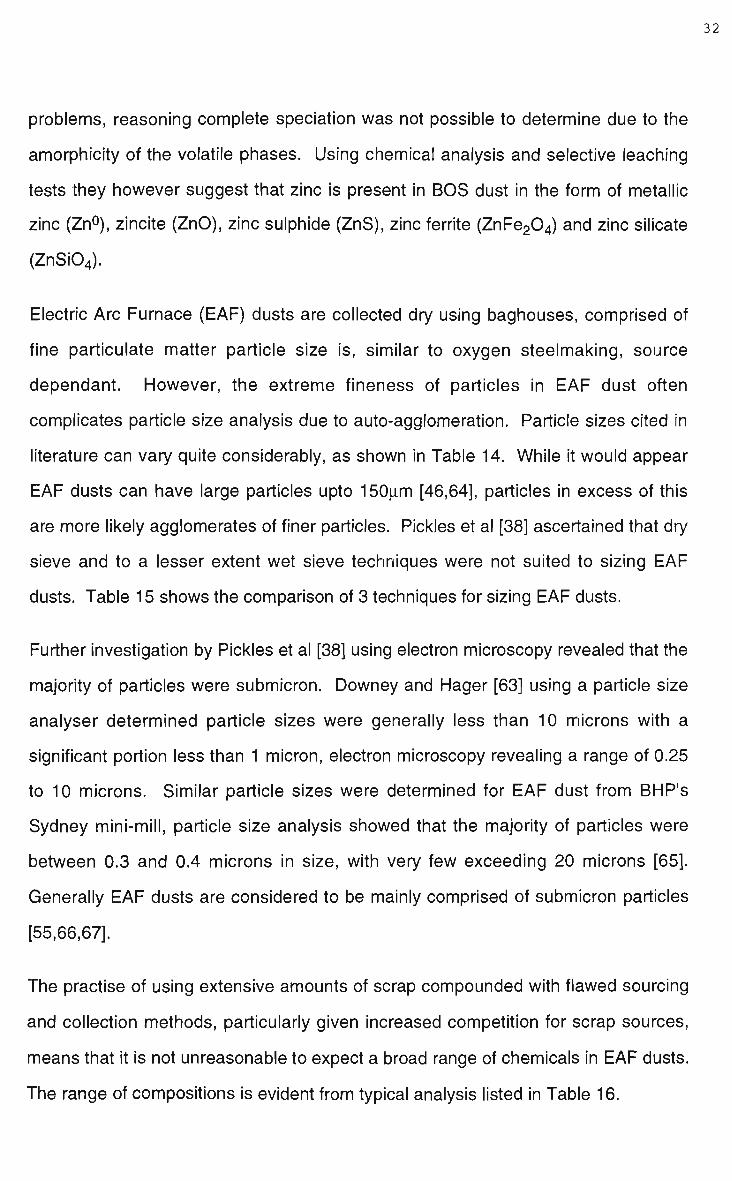
Electric Arc Furnace (EAF) dusts are collected dry using baghouses, comprised of
fine particulate matter particle size is, similar to oxygen steelmaking, source
dependant. However, the extreme fineness of particles in E A F dust often
complicates particle size analysis due to auto-agglomeration. Particle sizes cited in
literature can vary quite considerably, as shown in Table 14. While it would appear
EAF dusts can have large particles upto 150u.m [46,64], particles in excess of this
are more likely agglomerates of finer particles. Pickles et al [38] ascertained that dry
sieve and to a lesser extent wet sieve techniques were not suited to sizing EAF
dusts. Table 15 shows the comparison of 3 techniques for sizing EAF dusts.
Further investigation by Pickles et al [38] using electron microscopy revealed that the
majority of particles were submicron. Downey and Hager [63] using a particle size
analyser determined particle sizes were generally less than 10 microns with a
significant portion less than 1 micron, electron microscopy revealing a range of 0.25
to 10 microns. Similar particle sizes were determined for E A F dust from BHP's
Sydney mini-mill, particle size analysis showed that the majority of particles were
between 0.3 and 0.4 microns in size, with very few exceeding 20 microns [65].
Generally E A F dusts are considered to be mainly comprised of submicron particles
[55,66,67].
The practise of using extensive amounts of scrap compounded with flawed sourcing
and collection methods, particularly given increased competition for scrap sources,
means that it is not unreasonable to expect a broad range of chemicals in EAF dusts.
The range of compositions is evident from typical analysis listed in Table 16.
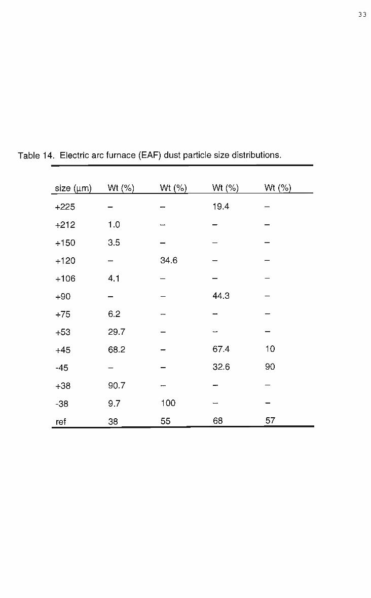
33
Table 14. Electric arc furnace (EAF) dust particle size distributions.
size (|im)
+225
+212
+150
+120
+106
+90
+75
+53
+45
-45
+38
-38
ref
Wt (%)
—
1.0
3.5
—
4.1
—
6.2
29.7
68.2
—
90.7
9.7
38
Wt (%)
—
—
—
34.6
—
—
—
—
—
—
—
100
55
Wt (%)
19.4
—
—
—
—
44.3
—
—
67.4
32.6
—
—
68
Wt (%)
—
—
—
—
—
—
—
—
10
90
—
—
57

34
Table 15. E A F dust particle size distribution determined by 3 different sizing
techniques [38].
size wt(%) wt(%) wt(%)
(u.m) dry sieve wet sieve Particle size analyser
+53
+45
+38
-38
+23.6
+18
+12.5
+9.5
+7
-7
29.7
68.2
90.3
9.7
—
—
—
—
—
_
11.2
13.4
13.7
84.6
—
—
—
—
—
^
—
—
—
—
0.6
1.8
3.0
4.1
5.3
94.7

35
Table 16. Electric arc furnace (EAF) dust chemical composition (wt%).
Fetotai 35.1 17.0 30.2 30.2 24.5 28.8 14.0 - 27.4
Fe2+ ___2.8-----
Fe3+ - 40.0 - 34.4
Si02 5.3 3.6 4.5 4.8 4.7 - 4.5 4.3 3.5
Al203 - 0.8 1.2 2.4 - - - 0.9 0.8
MgO 3.8 4.0 2.9 1.3 - 2.7 - 2.8 2.3
CaO 4.7 17.1 5.0 5.1 4.4 11.9 44.6 8.9 12.3
S - 0.45 0.6 0.3
PbO 1.6 4.5 3.7 4.1 3.9 2.4 8.5 2.1 0.2
ZnO 19.2 31.5 25.2 24.2 32.5 23.4 22.0 23.9 29.1
C - 0.5 - 1.7
CI 1.0 - 3.3 5.0 - 2.0 -
K20 0.82 2.1 1.1 - 4.0 - 1.4 3.1 0.07
Na20 0.62 - 1.8 - 4.2 - - 1.6 -
MnO 3.7 1.8 5.1 2.8 2.9 6.7 3.1 - 2.3
Ref. 63 38 66 55 69 70 71 72 65

36
Chemical homogeneity has also been found to vary with particle size [46,63].
Downey and Hager [63] used E D S analysis to reveal that sub-micron particles had
consistent composition while larger particles were not completely homogeneous.
However, Downey and Hager make it unclear whether this is a solidification effect or
a statistical variation due to auto-agglomeration of fine particles. EAF dust particles
are generally spherical, a large portion being cenospheres, large irregular particles
on closer examination tend to be agglomerates of fine sub-micron particles.
The mineralogy of EAF dusts has been studied extensively by Hagni and his co
workers [46,64,72]. Characterisation was performed using numerous techniques
including reflected light and electron microscopy, S E M - E D S and XRD. Iron species
identified included wustite (FeO), magnetite (Fe304), hematite (Fe203), and fayalite
(Fe2Si04), while zinc was predominant as zincite (ZnO), and zinc ferrite (ZnFe204).
EAF dusts were also found to contain numerous solid solutions and a mineralogy
which varied with particle size.
It is evident that current literature concerning characterisation of iron and steelmaking
dusts lack depth in so far as dusts generated by blast furnaces and oxygen
steelmaking. Understandably E A F dusts appear to be more thoroughly
characterised, conceivably BF and B O S type dust will receive further attention as
their recycling becomes an operational issue in the near future. Improved
interpretation could possibly be attained with further development of diagnostic tools,
which together with solidification science may provide a more useful understanding
of dust characteristics.
2.4 Considerations for Recycling and Disposal of Steelworks Dust.
When a waste is generated there is only two handling options, recycling or disposal.
Traditionally steelworks dusts have been dumped, for both technical and economic
reasons, rather than being recycled. Where environmental regulations have not

37
been restrictive iron and steel producers have disposed of dusts by landfill rather
than overcoming the problems of recycling. However, many companies have begun
to realise that levels of recycling currently employed are unlikely to be acceptable in
the future [41], recent industry surveys have shown that producers are particularly
concerned over future liability of landfills [31]. Increasing tonnages of collected dust
and tightening environmental protection policies however has seen the cost of landfill
dumping increase. Landfill dumping is itself not problem free, concerns have been
raised over the potential for toxic materials to leach from the dusts into the natural
water tables.
Opinion of the effort, or even the ability, of the iron and steel industry to self-manage
their waste problems are as broad as the industry itself. In the 1995 Sir Julius
Wernher Memorial Lecture the steel industry was credited as being uniquely
versatile, dynamic and technical innovative, yet sensitive to societal pressures [73].
However others are more candid, arguing that as a whole the industry is viewed with
particular suspicion [31]. A specialist industrial waste recycler, D K Recycling und
Roheisen G m b H , recently expressed their views on the European steel industry,
being "surprised by.... almost total lack of any systematic collection and recovery
outside the traditional scrap business" [74]. While Szekely raised the issue that the
industry does not have suitable infrastructure or resources to solve their
environmental problems on their own [19]. McManus's 1996 survey highlighted that
in general the industry felt that solid waste management would become more
stringent, and as such many companies were adopting pro-active approaches to iron
and steelmaking wastes [21].
One such example is the approach taken by British Steel pic, landfill tonnages were
drastically reduced by implementation of 3 waste handling routes; recycling within the
existing processes; pre-treatment followed by recycling; and off-site sales [32].
Recycling in many cases has not been an attractive option as the chemical and

38
physical properties of the dust hinder pyrometallurgical treatment whilst dumping has
been relatively cost effective.
The primary factor in determining the fate of wastes appears to be economic,
although the potential resource value of wastes have long been recognised,
economic reality, because of the substantial capital investment required, has meant
that recycling has been unattractive. D'Alessio and Lu [75] suggest that successful
recycling, apart from being economically viable, also needs to be environmentally
sustainable, while Beckovich [76] adds a further stipulation suggesting recycling
needs to be compatible with changing regulations. Piret and Muller in recognising
that treatment of low zinc bearing wastes is unlikely to be profitable argued that the
criteria for recycling is the ability to: generate a suitable feed material for steel
production; generate a suitable non-ferrous by-product for zinc smelting; and
generate a non-hazardous waste material for disposal [57]. Piret and Muller [57]
define recycling as being either an induced or forced activity. At low zinc levels
recycling is not economic and therefore it is argued that recycling will only occur
because environmental regulations force the activity; although it is reasonable to
speculate that the majority of producers would probably prefer the term
environmentally induced recycling. At higher zinc levels recycling activity becomes
induced because it is economically viable. The underlying cost considerations for
recycling, in terms of zinc content, are shown in Figure 5.
Typically the first steps in developing a recycling program are to utilise existing empty
plant capacity, British Steel recognised that landfill could be reduced by selective
recycling through the sinter plant, blast furnace, and B O S vessel. The factors
determining which route was most suited were the ferrous and tramp element
contents, and the particle size of the waste [32]. Similarly other companies have
recognised the potential of empty capacity in existing operations for recycling wastes.
Tata Steel considers their sinter plant to be the "waste receptacle of the steel plant"

39
1 ooo LEGEND
Value of total zinc content Value of recoverable zinc content Unit price of zinc-bearing secondary Cost of processing of zinc-bearing secondary Credit for DRI-product Break-even point
Zinc content
Figure 5. Cost considerations for recycling zinc bearing wastes [57].

40
[40], while Inland Steel has spent considerable effort developing their W O B (Waste
Oxide Briquettes) processes for recycling in the B O S [42].
The problems encountered when recycling "as collected" dusts are well documented
[40,54,60,66,77]. Small amounts of dry dust can be used as feed for sinter however
their fine particle size tends to reduce sinter permeability, while the moisture content
of sludges (wet collected dusts) creates further problems [39,40,53]. Recycling
through the sinter plant requires extensive blending [22], typically the sinter plant can
accommodate upto 4 w t % of mixed dust, operating practise has found that beyond
levels of 6 % productivity and sinter reducibility decrease [61]. Often recycling
through the sinter plant is restricted to selected low impurity materials, typical is the
approach of Krupp Hoesch Stahl A G who only recycle coarse grained B O F sludge
through the sinter plant, the sludge containing less than 0.5% zinc [78]. Difficulties
are encountered when recycling steelworks dusts in the blast furnace due to the
presence of refluxing elements such as zinc and lead. Zinc is difficult to remove from
a blast furnace once it has entered the process stream, its refluxing nature can cause
problems associated with zincite (ZnO) accretions which attack refractories and
reduces operating predictability of the furnace. The addition of fines can restrict bed
permeability, while many blast furnace operators would be hesitant to feed material
with a variable chemistry due to the potential to destabilise operating conditions. It is
this chemical variability which hinders many plants recycling dusts through the sinter
plant-blast furnace route [77]. Oxygen steelmaking is more tolerant of variable
chemistries typical in iron and steelmaking wastes, however the high velocity off gas
stream makes feeding unagglomerated dusts into a B O F difficult. Sludges require
de-watering, while fines are difficult, and expensive, to handle, unagglomerated fines
create problems when trying to assimilate into normal steelmaking operations.
Steelworks dusts also contain m a n y elements which are undesirable to the
steelmaking process [40], tramp elements, phosphorous and sulphur being
particularly detrimental, preferentially partition to the metal rather than the slag.

41
E AF dusts can be directly recycled although it is arguable whether this treatment
technique represents a true alternative [63], since this technique merely enriches the
volatile content of the dust, at some stage the dust still requires off line processing,
the economics of direct recycling are also questionable [71]. The fine particulate size
of EAF dusts creates handling problems and they also contain significant amounts of
halides. The halides content of E A F dusts is seen to be a potential problem as
halide elements such as fluorine and chlorine can interfere with pyrometallurgical
processes that occur in the furnace [45,63,79]. EAF dusts are of particularly concern
being classified by the Environmental Protection Agency (EPA - U.S) as a hazardous
material (K061) [80], E A F dusts are classifieds as hazardous because without
treatment they fail the toxicity characteristic leaching procedure (KCLP) for Pb, Cd
and Cr [76]. Direct disposal is generally regulated against, the majority of producers
using waste treatment companies to undertake mandatory processing.
Worldwide guidelines for handling steelworks dust are far from uniform, recycling
however is the favoured option by many governments (U.S and Japan)[81], society
also views this as the most viable alternative as concerns over dumping increase
[54]. Derby [34] however, claims that some current and regional(U.S) regulations
hinder societal influences and economic factors supporting recycling. Itoh and Fieser
[54] argue that by not adopting recycling or reclamation programs the industry is
bearing an economic penalty in terms of non utilised iron and carbon and the loss of
real estate. Gress and Sarko [81] take the recycling argument further with the view
that without a suitable alternative iron and steel production, in the future, may be
hindered. While the industry itself forecasts that future recycling strategies may
ultimately be based around facilities specifically designed for waste treatment [21].

42
2.5 Dust Treatment Technology.
It is widely recognised that the suitability of a dust treatment system is site
dependant, economic viability being dependant on local regulations, transport and
disposal costs, fuel and labour costs, and the volume and composition of the dust
[45,53,60]. For a new emerging process, Hay [35] believes that economic survival is
dependant on the quality of the end products and the efficiency of the process
compared to existing technologies. While in general, Schoukens et al [45] argue that
treatment systems are sensitive to the value of reclaimed materials, in particular zinc,
fluctuations in the market value of the reclaimed material, their content in the dust
and their cost of recovery will all affect economic viability. Ultimately recycling
technology development is based on economic viability, where recycling is either
environmentally forced or economically induced as illustrated in Figure 5.
The majority of commercial plants currently operating are pyrometallurgical, Serbent
et al [60] argue that for a pyrometallurgical process suitability should be based on 3
criteria; i) zinc and lead should be recovered and concentrated in the flue dust so as
to allow for the feed material to be recycled, ii) the process treats the material such
that further agglomeration is not required and iii) the treated material contains a high
grade of metallised iron. Given that the process is recycling a further suggested
criteria is that the process itself does not generate hazardous waste during
treatment.
Of the technologies discussed in literature the majority are concerned with treating
EAF rather than BF or B O S dusts, this is due to the higher zinc levels and the greater
concerns about material toxicity. Apart from pyrometallurigcal technologies the other
two process routes available for the treatment of steelworks dust are encapsulation
and hydrometallurgical technologies; although many treatment processes have been
proved to be technical feasible few have been developed beyond the pilot scale
stage.

43
2.5.1 Encapsulation.
Encapsulation or chemical fixation technologies consist of binding the dusts with a
solidification agent such as Portland cement or silicates, and can often involve high
temperature vitrification. These solidification agents lock the dust into an impervious
matrix through physical binding and chemical bonding, reducing the leaching
potential of the material. It is argued that the main disadvantage of this technology is
that the overall bulk of the waste is increased and that there is no actual metal
recovery [79]. Research has shown that EAF dust can be added to concrete as a
retarding agent [82]. The concrete encapsulates the dust which retards setting due
to the presence of zinc and pozzolanic compounds. Although the addition of EAF
dust improves mechanical properties, as only 2 -3 w t % can be added the potential of
this method for treating large tonnages of waste is limited.
Several encapsulation processes are currently in operation including the Super
Detox Process [83] and the Glassification Process [84,85]. The Glassification
Process, originally developed for Oregon Steel Mills, utilises E A F dusts to produce
an inert glass frit which is marketed as having a wide range of end uses. The dust is
mixed with glass formers, modifiers and other additives and melted at approximately
1400°C in an electric furnace before quenching to produce frit. The benefits of the
process are claimed to be: simplicity of operation; low capital investment with a short
payback period [84]; and no generation of waste [85]. A 12000 t/yr commercial plant
was commissioned in 1992 in Portland, Oregon, a schematic diagram of the process
is shown in Figure 6 [85]. Limited technical details of the process have been
published and it is unclear how the problem of cold feeding fine particulate matter to
the furnace was overcome and also whether the technology suffers from accretion
build-up since the furnace is cold-top designed and operates without a fugitive
emission collection system.

44
I OSM GLASSIFICATION1 Major Oxide Sources Supplementary Oxide Sources
Natural Sources
Limestone
Litharge
Quartz/ Sand
Dolomite
Feldspar
Borax
EAF Dust
-CaOfPoO; Slfjj.
Cat3,MgO,
AJ203, -
Nazi B20_3
Technical Grade Oxide
Cadmium Chromium
Arsenic
Cobalt
Nickel
Manganese
Zinc
*EAF,Dust«
: Cr304, As,03 CoO
?:Niq",:Mh6;;--A' ZnO"-
COMMERCIAL GLASS MANUFACTURING
Major Oxide Sources Supplementary Oxide Sources
Natural Sources
Limestone
Litharge
Quartz/Sand
Dolomite
Feldspar
Borax
fiH m
Technical Grade Oxide
Cadmium
Chromium
Arsenic
Cobalt
Nickel
Manganese
Zinc
Lwv.
REDUCTION CLASSIFICATION
MARKETS
Roofing Materials
Ceramic Tiles
Glazes/Colorants
oihers
Figure 6. Inputs and flowsheet for the Glassification process [85].

45
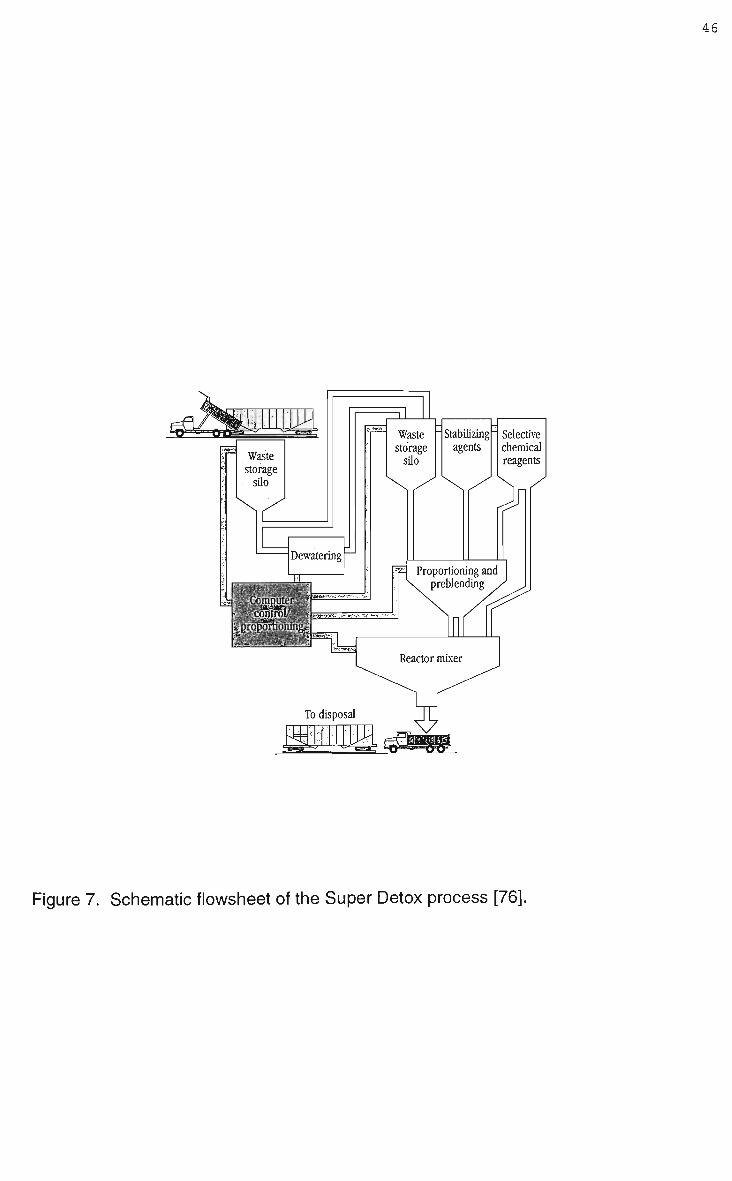
The Super Detox process was originally developed by Bethlehem Steel for
stabilisation of E A F dust [83]. Stabilisation is achieved by mixing the dusts with
alumino-silicates, lime and other additives, stabilisation being attributed to multiple
reaction mechanisms including reduction, oxidation, polymerisation, and pozzolanic
bonding and solidification [76]. Initial operating reports indicated that not all treated
material meet statutory requirements for leachability, even after extended curing
times, and that some reprocessing was required [83]. Later published data is vague,
but it would appear that curing is no longer essential [86]. As of 1996 3 plants were
operational, however plans to develop a means to recover the resource value of the
waste have not eventuated with all of the treated, concrete like, material still being
landfilled. However the operators argue that the Super Detox process generates
less landfill compared to high temperature metal recovery (HTMR) processes
because the Super Detox material has a much higher density than slag from H T M R
processing [86]. However this argument could be refuted as many H T M R processes
can sell their slag, leaving no wastes for landfill. Keypoints of the process are
speculated to be the precision of additive additions and the kinetics of the
stabilisation reactions that occur in the Reactor Mixer, a schematic diagram of the
Super Detox process is illustrated in Figure 7 [76].
The Inorganic Recycling (l/R) process is an encapsulation technology based on
vitrification [81]; being designed to suit medium size dust producers, i.e. 8000 to
15000 tonne/year. Dusts and silicates are mixed on a batch basis together with
priority chemicals to aid binding, this mixture is then feed into a continuously run
furnace operating between 800 and 1400°C. Volatile matter is fumed off and
collected in a scrubbing system while the remainder of the material vitrifies then
melts, the melt being water quenched as it flows from the furnace, a flow chart of the
l/R process is shown in Figure 8.
Gress and Sarko [81] claim that the l/R process "allows complete control and
significant reduced liabilities" when treating EAF dusts, producing a vitrified ceramic,
46
Figure 7. Schematic flowsheet of the Super Detox process [76].

47
SCHEME I
CUifOUER SUPPLY
SCHEME II
SLUDGE SLURRY TANK
GRAPPLE INTO 1 YARD CONTAINERS
l/R CHEMICALS
Recycling Unit #1
SILICATES
dt> dts STACC FOR SHIPPING
2500/ BAGS
l/R CHEMICALS
TEST COMPOSITE SAMPLE
Mixer/Reactor
-*0-i r Surge Tank
LP^ggDgg
FILTER PRESS
TZ
X—7
-ts CERAMIC PRODUCT BACCINC
souos RETURN TO MIXER
SCRUBBER 5YSTEM
Unit #3
~T— END PRODUCT •
Recycling Unit #2 • 0
WATER QUENCH
VITRIFIED CERAMIC PRODUCT TESTING
RECYCLING UNIT tSOO -2300 DEC. r
PRODUCT EXIT
Figure 8. Flowsheet of the Inorganic Recycling process [81].

48
and because of the high zinc content, a dust rich in zinc oxide. The mixing and
blending component of the process allows for batch processing and sufficient
flexibility so that product chemistry can be altered to suit feed material and product
requirements. The vitrified ceramic produced by the l/R process is marketed as a
potential abrasive, architectural product and refractory. An l/R process was
commissioned in 1993 for treating wastes from a flat roll plant (Hickman, Arkansas),
reported operating difficulties eventually saw the plant close before re-opening after
further development [48].
2.5.2 Pyrometallurgical Processes.
Numerous companies have developed pyrometallurgical processes for treating iron
and steelmaking wastes. History has probably much to do in seeding original
research programs, the failure of tentative steps at direct recycling through existing
infrastructure leading to the development of specialised waste treating
pyrometallurgical processes. Given the considerable research into the technology it
is not surprising the number of innovative processes which have been developed, yet
significantly the success and commercial adoption of this technology would appear to
be faltering.
Rotary kilns, such as the Waelz Kiln, continue to be the most prevalent technology
for treating steelworks dust, as of January 1993 14 such kilns were in operation
worldwide [45] including those operated by Berzelius, Horsehead Resource
Development and Shisaka [87].
The suitability of a rotary kiln for processing steelworks dust has been found, in
operating practise, to be dependant on waste characteristics, particular consideration
being paid to the particle size of the waste and the chemical composition [60]. The
fineness of steelmaking dusts necessitate that some agglomeration is usually

49
performed so as to avoid material losses in the drying zone while furnace charging.
The iron content of the dusts is important due to the danger of premature softening of
the furnace burden, high wustite levels for acid burdens can result in fayalite slag
formation and softening, during kiln operation burden chemistry is closely monitored
particularly with respect to the wustite levels. Similarly, premature softening can
occur due to the presence of alkalies. Although not a technical problem the non-
ferrous content of the dusts is important, at low levels it is likely that a rotary kiln
process will be uneconomical, until recently it was considered that rotary kilns were
only viable for processing dusts with high zinc contents (>20%) [38].
A generalised flow sheet for processing zinc bearing waste through a rotary kiln is
shown in Figure 9 [56], while Figure 10 illustrates the basic principles of the rotary
kiln [88]. Steelworks dust are mixed with a reducing agent (commonly coke breeze),
pelletised, and then preheated before being fed into the gas-fuel fired rotary kiln.
Preheating temperatures vary between commercial variations of the rotary kiln, but
are typically in the range of 200 to 800°C [56]. The carbonaceous material,
contained in, and added to the dust acts not only as a reductant but also as a fuel
source. Metal bearing dusts typically constitute 7 5 % of the pellet while the remainder
is reductant and sometimes binder [39], normal operating practise fills the kiln to a
level of 2 0 % , with the residence time being approximately 4 hours [89]. Volatile
oxides, such as zinc and lead, are reduced carbothermally, once driven off from the
bed these metal vapours are then reoxidised. Counter current gas flow removes
oxidised metal vapours from the kiln where they are collected as baghouse dust, this
dust is commonly referred to as Waelz Oxide[45]. Halide and alkali compounds
contained in the dust are volatilised while the extent of iron oxide reduction is
dependant on the amount of reductant available in the process. Typically, iron oxide
is only partially reduced leaving a metallised pellet and a slag containing iron, the
toxic teachability of the slag being low enough that it is considered safe for disposal.

50
RECYCLE
DRY DUSTS
COAL OR COKE BREEZE
71 r~ I MIXER I
PELLETIZER |
i
LUMP' COKE
PREHEATER J
T REDUCTION KILN
I }
COOLER }~
MAGNETIC SEPARATION
SCREEN
PRODUCT
WET DUSTS
FILTER
DRYER J
ZINC COLLECTION
•WATER
OFF-GAS
Figure 9. Typical process flow sheet for treating zinc bearing waste in a rotary kiln
[56].

51
AIR:
AIR
SPONGE IRON I*
X>CHARrlFr77/////,VlZZZ 7~7~
[• CHAR) REDUCTION ZONE r* PREHEATING ZONE -h-lv
ORE+REDUCTANT (•CHAR)
/WASTE GAS
FeO+CO^Fe+C02 C02+C *2CO
2FeO + C=rFe*CO
Figure 10. Basic principles of rotary kiln operation [88].
52
Variants of the rotary kiln that have been commercialised include the Kawasaki Kiln,
the SL/RN process, Sumitomo's S D R and SPM, and the Waelz kiln [77]. Horsehead
Resource Development company (HRD) are the largest user of rotary kilns for
processing steelmaking wastes [48]. H R D operate at 3 sites across America,
treating EAF dusts in a proprietary version of the Waelz kiln, these plants run as
custom operations charging a treatment fee for the processing. H R D utilise a 2
stage process, the initial stage separates iron from the volatile metals, the iron
residue material (IRM) being marketed as an aggregate, anti-skid or water treatment
material [34]. F u m e generated in this first stage is collected and then processed
through a second Waelz kiln, removing most of the zinc as zinc oxide calcine whilst
producing a fume rich in lead, cadmium and halogens. Both of these products from
the second kiln are sold and further treated to recover their metallic value. Recent
developments at H R D have resulted in the metallisation of the IRM increasing,
continuing research is aiming to develop an IRM grade with DRI type properties that
would be suitable as a scrap substitute for EAF steelmaking [76].
Single stage treatment processes are more common in Europe, typical is Aser SA
who operate a Waelz kiln near Bilbao Spain, the kiln is based on the Berzelius
variant and is used for treating EAF dusts [87]. The kiln is 50m in length with a
working volume of 377m 3 and treats 70000 tonnes per annum of E A F dusts
producing 24000 tonnes of Waelz oxide and 50000 tonnes of slag. The Waelz oxide
is rich in zinc and lead (54 - 56 and 9 - 1 1 % respectively) while the majority of the
iron reports to the slag (34 - 3 8 % FeO). Unlike potential developments in HRD's
rotary processing no attempt was made to recover the iron units from the slag.
Unlike earlier rotary kiln processes the Inclined Rotary Reduction System (IRRS)
developed by Zia Technology Inc. (ZTI) was conceived to fully reclaim the resource
value of EAF dust [83,90]. EAF dust is pelletised with pulverised coal, and a binder,
and then fed to an oxy-fuel fired rotary kiln. Zinc and lead are ultimately captured by
a splash condenser, while residue from the rotary kiln is highly metallised and

53
reportedly similar to DRI. Not fully elaborated on in original published literature is
how ZTI would overcome the technical difficulties associated with operating a plant
that contains two separate technologies, as illustrated in Figure 11.
Increasingly rotary kilns are being investigated for processing low zinc bearing
wastes, namely BF and B O S dusts. The work of Serbent et al [60] appears to be
one of the earliest (1974) successful attempts at treating a mixture of BF sludge and
B O F dust in an industrial Waelz kiln. Testing was performed with a blended 1:1
mixture of BF sludge and B O S dust with supplementary lime being used to adjust
basicity to 1.5. A disc pelletiser was used to produce pellets in the range of 2 to
20mm, the pellets, containing 4 4 % total iron and 4.5% zinc, were charged to the kiln
with coke breeze, the coke constituting 3 5 % of the total kiln burden. The main aim of
the trial, to evaluate the potential of the rotary kiln for dezincification, was
demonstrated to be feasible over a months continuous operation. Volatilisation of
zinc and lead was reported to be in excess of 95%, the kiln discharge containing less
than 0.05% zinc and typically 6 0 % total iron with upwards of 9 0 % metallisation,
making the residue suitable for BF feed.
Sumitomo Metal Industries have developed 2 rotary kiln processes for treating low
zinc bearing wastes. The Sumitomo Dust Reduction (SDR) process being developed
at the W a k a y a m a steelworks and the Sumitomo Prereduction Method (SPM) being
developed at the Kashima steelworks, process flowsheets are illustrated in Figures
12 and 13 respectively [53].
In the S D R process pellets, 8 to 15 m m in diameter, are made from steelworks dust
and sludge mixed with ground coke, the reducing agent, and 1 % bentonite as a
binder [53]. Ground coke is added as supplementary carbon as the dust/sludges
contain insufficient carbon for complete reduction. However, operating practise has
shown that increasing carbon content decreases pellet strength so that carbon
additions are balanced between a minimum required for efficient dezincing whilst
maintaining sufficient pellet strength.

54
FILTER
_SZV EAF DUST COAL BINDER
COAL ZnO. PbO BINDER H
PELLETS
CH4
O,
PELLETS
IRRS FURNACE
AFTERBURNER AND RETORT
Pb, Cd.
VAPORS
DRI (FLUXED) RES
ZnO, PbO CdOl C02
Zn, Pb, Cd
SPLASH CONDENSER
DUE Zn, Pb, Cd METAL
Figure 11. Flowsheet for Inclined Rotary Reduction System (IRRS) process [90].

55
ap-cusr- SLURRY
BOP-BUST-SLURRY
DRY-OUSTS
\ /
'-r
V 41 L—
<D
V
•
J J
J 'a.1 J _ j.Mr
Lv THICKENER
(?) DUST • 9INS
(?) TU8E • MILL
(4)hltXNG-TANK
r7\ SLURRY-^BASINS
(^FILTERS
(?) SCALE
,0, ROTARY-^DRYER
(?) BURNER
MATERIAL-SIN BENTONITE-BIN
(lZ)3AS- FILTER
Fig. 1 (Top & Bottom)—Process flow of SDR process in Wakayama Steel Works
OJO I.1.'.'.1.'.-! q
» a
§ DISINTEGRATOR
KNEADER
SURGE BINS
§PELLET1ZERS
PREHEATER
(Ti) KILN
@ SHELL-FANS
(20) BURNER
(2?) COOLEH
||) BAG HOUSE
§ BURNER
BAG HOUSE
(25) ZINC OUST- BIN
Q " P |/=? =p P (26) COKE BIN
(J I—i-
O 3
W I
•*>4
W
Figure 12. Sumitomo Dust Reduction (SDR) process flow sheet [53].

56
BF. dust slurry BCF. oust slurry Mill scale Yard dust slurry
2nd thickener
3asin
I Rotary dryer
50=50-I
Bag house
•-0LHT""! Raw material dust bin
_ , Anthracite
Q 0 bin H n Stack
U J O
Rotary kiln I (39rr*x80mU
u=$ Rotary cooler (L9m#*10mL)
Screen > *7r
(J IX U-'
Bag house ]
~W"i 1
Zinc dust Return bin
-7 mm
-•Sponge iron (Blest Furnace) -"Sponge iron ( Sinter Plant )
Figure 13. Sumitomo Prereduction Method (SPM) process flow sheet [53].

57
Sensible heat from the rotary kiln preheats (200°C) the pellets prior to charging
together with small amounts of lumpy coke, the coke helps to maintain reducing
conditions at the charge end and also minimises ring formation in the kiln. Typical
operating temperatures for the kiln are between 1100 and 1150°C, processing in the
rotary kiln not only removes volatiles, such as zinc and lead, but also produces a
metallised pellet residue. Metallisation occurrs via direct reduction mechanisms
because of residual carbon in the pellets.
Dezincing is aided by the design of the kiln, a dam of fire bricks located in the kiln of
the discharge end helps maintain high temperatures and a reducing atmosphere
around the pellets. Reported analysis of dust collected from the off gas would
suggest that the process suffers badly from dust carryover, a typical dust containing
only 1 4 % zinc, 4 % lead, with 2 6 % iron and 1 8 % carbon [56]. Although dust
carryover appears to be a problem, zinc removal rates are better than 95%, with
N a 2 0 and K 2 0 also being reduced by approximately 5 0 % . Metallisation of the
pellets however can be quite high (95%) but is more typically in the range of 90 -
95%; low zinc, less than 0.1%, together with a gangue content of upto 1 0 % makes
the residue suitable feed for the BF.
A key element to the stable operation of the S D R process appears to be the ability to
control burden chemistry by blending, particularly the supplementary carbon
additions. Kanda et al [53] reveal that extensive research had been undertaken to
determine suitable practises for waste agglomeration and kiln operation. The S D R
process is claimed to have low energy consumption, and a productivity comparable
to other rotary kiln operations.
Sumitomo's S P M process differs from the S D R process in that there is no preheating
or material agglomeration prior to kiln charging. Similar to the S D R process
extensive blending is required, the dried blended mix is then charged into the rotary
kiln together with anthracite at a ratio of approximately 10:1, the anthracite being

58
added as a supplementary carbon for reduction. O n charging, reduction,
volatilisation and partial agglomeration of the feed material occurs, agglomeration
occurring because kiln temperatures are sufficient to cause material softening and
melting. The agglomerated residue is then passed through a rotary cooler and sized,
oversized material being used as BF feed while the undersized portion is suitable for
sinter plant feed.
In comparison to the S D R process, the residue from the S P M process has a higher
zinc content, approximately 0.1 - 0.2%, and a lower degree of metallisation, 85%.
Kanda et al [53] in comparing the S P M and S D R processes recognise that because
of lower capital and running costs the S P M provides cheaper treatment, however the
S D R process produces a much higher quality feed suited to the blast furnace.
Kanda et al remain indecisively neutral on which process is superior, arguing that
suitability is site dependant. However, the lack of published details for the S P M
process would suggest that the S D R process is more favoured by Sumitomo.
It is clear that although marketed as different technologies the rotary kiln processes
have many similar features. Similarities include the need for extensive material
blending, operating temperatures, reductant types, and that a hot metal product is
not directly produced, nor is zinc or lead directly recovered. Rotary kiln processes
are also inherently capital and energy intensive [56] and are likely to be only
economically viable when treating wastes containing high levels of zinc or when local
regulations force treatment. Although currently Lurgi is developing an Energy
Optimised Waelz (EOW) process which is aimed at drastically reducing the level of
coke consumption in existing processes [89].
The Inmetco process is one of a number of processes which were conceived
specifically around producing a hot metal product, other processes include Elred, the
Extended Arc Flash Reactor (EAFR), and the Inred process.

59
The Inmetco process was commercialised in 1978 and was initially developed to
recover Fe, Cr, and Ni from speciality steelmaking wastes [91], by the mid 1980's the
scope of the process had expanded to also include treatment of low zinc bearing
wastes [20]. However, showing the cyclic nature of the market a more recent
statement claims that Inmetco, the company, has no interest in treating carbon steel
wastes because it is outside of its core business, although it would sell the
technology to other companies [92].
The heart of the process is the rotary hearth furnace, shown in Figure 14, where
reduction and volatilisation reactions occur. The furnace operates counter-currently
and is annular in shape with a diameter of 16.7m [93]. Waste material is carefully
sized and then blended together with lime and crushed coke, pelletising is then used
to produce pellets upto 1 2 m m in diameter. Dried pellets are charged to the rotary
furnace where they stack upon each other upto a 3 deep layer as shown in Figure
15. Charged pellets are heated to between 1225 and 1250°C by the counter flowing
gas in the furnace, oxides are reduced by carbon within the pellets, the volatile
metals driven off are then cleaned from the furnace off gas as oxides. This material
was originally landfilled [91], but is more recently deemed suitable for down stream
recovery of zinc and lead [94]. Furnace retention time is typically 15 minutes, during
the single revolution the pellets have metallised to a level of 9 0 % or greater. The
metallised pellets are then directly hot charged to a submerged arc furnace to
produce pig iron, or briquetted, cooled and stored for later use. Recovery rates for
iron are reported to be greater than 9 5 % [93].
Claimed advantages of the Inmetco process include the absence of a thermal
hardening stage during material agglomeration, minimal pellet sticking during
processing, and low dusting due to minimal pellet to pellet interaction [91,94].
However, the low level of dust generated by the rotary hearth furnace can be partly
attributed to the use of binders (1-3wt%) in the process. Examination of early
published data, where binders were not added, indicates that dust carryover was
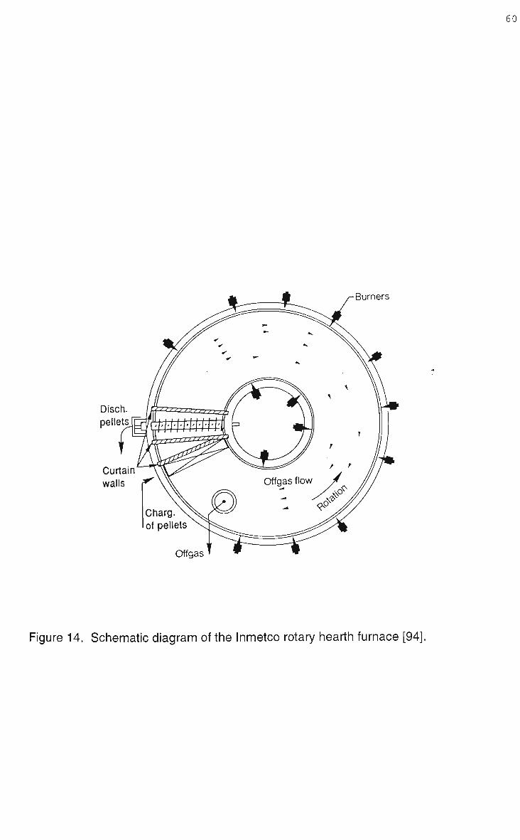
60
Burners
Disch. pellets
Curtain walls
Offgas
Figure 14. Schematic diagram of the Inmetco rotary hearth furnace [94].

61
/ / / / / / / / / /
/ Process off-gas CO.C02 / V / / .
H2. H20 / ' / / / / f / / f Energy input by / / / / /-""radiant heat ' / / / /
V^AAA^ Ore/coal green pellets
• • • Rotary hearth *-
Figure 15. Pellet layering and reaction mechanisms as per the Inmetco process [94].

62
quite high. The addition of binders has reduced dust generation considerably, the
iron content of the off gas dust falling from 9 % [93] to 1.5% [94]. Binders are now
considered essential for minimising pellet disintegration due to thermal shock [94].
As with many other processes operational stability, of the rotary hearth furnace,
appears dependant on the ability to control pellet chemistry through blending. The
suitability of the Inmetco process is claimed to be site dependant, however, what is
not specified is the level of maintenance required for a large, complex piece of
machinery such as the rotary hearth furnace.
Plasma technology has been investigated, successfully, for treating steelworks dusts
since the mid 1970's . Pickles et al [38] investigated the potential of a small 25kW
extended arc flash reactor (EAFR), schematically shown in Figure 16, for treating
wastes from an integrated iron and steel plant.
Steelworks wastes were mixed with supplementary carbon and then fed into the
EAFR, waste material passing through 3 well defined zones within the reactor: a
preheating zone; a flash zone; and the plasma zone, molten material then collecting
in the reactor hearth. Residence times were found to be very short, less than 1
second, due to the high surface area to volume ratio of the wastes and extremely fast
gas-solid reaction rates encountered in the flash chamber and plasma zones. By
controlled material blending it was possible to produce waste mixtures which
contained sufficient carbon so that additional sources of carbon were not required for
reduction, producing iron alloys with a wide range of carbon contents. Metal
recovery rates varied with the waste mixture used, but were generally in the order of
90%. The trial work demonstrated that as far as waste processing was concerned
the E A F R was not overly sensitive to feed material, although its energy requirements
did vary according to waste type. However, a limitation of the research was the
design of the 2 5 k W reactor, off gas was not extracted during processing, so the

63
3. Extended arc zone
Gas
Spout
Figure 16. Extended Arc Flash Reactor (EAFR) 25kW experimental system [38].

64
effect of using unagglomerated feed on dust generation can not be thoroughly
evaluated.
As demonstrated by the EAFR system plasma processes do not extensively rely on
steelworks dust being agglomerated prior to furnace charging. Unagglomerated feed
was used by International Mill Service Inc. (IMS) who developed a plasma process to
treat EAF dust, based on the Tetronics plasma torch [80] as of 1995 4 plants had
been commercialised [95]. Thermal processing, reduction and vaporisation, is
achieved in the slag bath of the furnace which utilises a D C transferred plasma arc
operating with a single hollow graphite electrode. Figure 17 shows a flow chart for
IMS's plasma process.
EAF dust is mixed, 10:1, with reductant, coke breeze, and gravity fed into the top of
the plasma furnace, rapid reduction occurs in the molten slag bath which is
maintained between 1400 - 1500°C. Carbothermic reduction is followed by
vaporisation of zinc and other volatile metals, the off gas stream removing the
vapours, claimed operating performances for zinc removal being better than 9 7 % .
The plasma furnace is ducted directly to a splash condenser so that zinc, lead and
cadmium can be collected from the off gas stream, after which it is passed through
an after burner which oxidises remaining carbon monoxide, remaining particulate
matter is collected in a baghouse. The process is controlled such that complete
reduction of the iron oxides is avoided, iron is only partially reduced and remains as
wustite with the slag phase, which is periodically tapped from the plasma furnace.
The slag is the largest volume product of the process [80] and is suitably inert that it
passes the TCLP test [83]. Technically iron could be fully reduced but the process
operating parameters are governed by economics, increasing the reductant additions
increases iron and zinc reduction however more power is then required to drive the
plasma [95]. Commissioning of the first 2 IMS plasma plants began in 1989 [95]
where it quickly because apparent that the key to the whole process was the ability to
collect zinc in the splash condenser [80]. IMS are relatively candid about the degree

65
- Particulate
Baghouse Filter
Afterburner
J" % =
Air-Jnnv
Zinc Metal "SCDR"
Zinc Condenser
Electrical Energy
Carbon
Plasma Furnace
Slag
Figure 17. International Mill Service Inc's plasma process for treating E A F dusts [80].

66
of startup problems encountered with the process, particularly operation of the splash
condenser. Although the process was treating EAF dust successfully the efficiency
of the condenser rarely reached 8 5 % and was typically running at 60-70% [95].
Difficulty was also encountered with high levels of iron contamination in the zinc
metal [48] and although not elaborated upon this may explain why a late process
refinement resulted in the addition of supplementary fluxes to the furnace charge
[95]. However, economic pressures, due to poor zinc recovery and quality,
eventually saw IMS close down their plasma process plants.
Similar reasons appear to have also stalled commercialisation of the Enviroplas
process. Under development by Mintek (South Africa) since the late 1980's the
plasma technology is founded on treating high zinc (EAF) or alloy steelmaking
wastes. Mintek believe that economic viability is dependant on waste treatment
premiums and the ability to recover zinc, economic analysis by the company
suggesting that the process requires 10000 tpa of waste with a zinc content of
greater than 2 0 % [96]. The Enviroplas process utilises a D C plasma transferred arc,
the reactor operating with a single hollow graphite electrode as the cathode and the
open molten metal bath as the anode, as shown in Figure 18 [97]. Pursuit of zinc
recovery saw the installation of a lead splash condenser in 1994/95 linked to a 3 M W
Enviroplas demonstration plant [98].
Processing of E A F dust is achieved by mixing the dust (10:3) with anthracite and
sufficient silica to adjust the basicity to 1 [97]. Although Mintek advertises one of the
advantages of their hollow electrode feeding system is that it enhances the ability to
feed unagglomerated material to the plasma furnace, published trial descriptions
indicate that the EAF dust mixture was always pelletised [45,96,97,99,100].
Pellets are fed into the furnace bath through the hollow electrode and undergo
carbothermic reduction. Slag and metal are tapped periodically, while off gas is
passed through an after burner to ensure complete combustion of carbon monoxide.

67
Cathode
Off-gas port
AI2O3 refractory
MgO refractory
Steel shell
Molten bath
Multiple-pin anode
Hollow electrode
M g O plug
Feed port
Conical roof
Plasma arc
Taphole
Anode
Figure 18. 200kW Enviroplas D C plasma furnace as used by Mintek [97].

68
In early trials the volatile metal vapours contained in the off gas, zinc and lead etc.,
were reoxidised and collected as baghouse fume, typically containing 7 2 % Z n O and
8 % P b O [97]. Metal quality produced in the plasma reactor is not reported upon,
company policy giving a higher priority to the slag which was found to pass standard
leaching tests for disposal [96]. Research into plasma processing of EAF dust have
been both practical and theoretical, particular use being made of the P Y R O S I M
package to investigate thermodynamic equilibrium conditions [97]. Given the crucial
role of zinc recovery in the overall process Mintek opted to install a lead splash
condenser, although trials have been not elaborated on it is evident that despite
using a hydrometallurgical step to first remove troublesome halogens, zinc quality
has still not been perfected [98]. Operation of the pilot and demonstration plants
however has made it evident that feed chemistry effects furnace control, as does
matching power input to feed rate [96]. As of 1997 the Enviroplas process still
appears hindered by equipment problems, reflected in poor zinc quality and recovery
rates, and as of yet a commercial plant for processing EAF dust has not been built.
A splash condenser is also used in the Plasmadust process. Development of the
Plasmadust process began in 1980 by SKF, with the first commercial plant being
built in 1982 [87]. A plasma torch heats a mixture of steelworks dust, coal dust and
silica, which is pneumatically blown into the bottom of a coke filled shaft furnace.
The process is typically operated so that iron is reduced and then tapped along with
slag; excess coke maintains a highly reducing atmosphere which prevents
reoxidation of more volatile metals which are collected from the off gas stream in a
splash condenser.
Unlike many other treatment processes Westinghouse Electric Corp. conceived the
Metrec process specifically to treat small tonnages of EAF dust [101]. In the Metrec
process unagglomerated EAF dust is fed into a hot plasma gas, the reaction zone
being created by passing a suitable hydrocarbon, such as methane, through a
plasma torch. Reduction occurs in the reducing gas phase, volatile metals being

69
recovered using a splash condenser, while iron is only partially reduced and remains
with the slag components. The plasma process is claimed by Westinghouse to have
several advantages in comparison to coke/coal processes. The Metrec process has
a very short retention time due to the reactions occurring in the gas phase rather
than a static solid bed, high temperatures ensure increased reaction and recovery
rates, while the use of hydrocarbon reductants introduce only negligible amounts of
sulphur, halides and refractory compounds into the process. As with other plasma
technologies no agglomeration of the dusts is required for processing.
Westinghouse have also investigated other technologies for processing wastes,
including a plasma fired cupola for treating low zinc bearing wastes which attained
recovery rates for iron in excess of 9 7 % [101]. Cupola technology has also been
investigated by Rostoker Inc. for treating a multitude of pelletised wastes [102], while
more recently Westinghouse plasma technology is being used in the Zinc Iron
Plasma Process (ZIPP) of Philip Environmental Inc. for cupola smelting of scrap and
EAF dust [92].
Unlike the plasma processes, agglomeration of feed material is required in the Elkem
process [45]. Briquetted EAF dust is smelted in the Elkem process using an airtight
3 phase electric resistance furnace. Zinc is directly recovered, however iron remains
as an oxide in the slag [103]. Marketed as an extremely energy efficient process
[242] the operating economics rely on treatment charges and a high throughput, and
are therefore very sensitive to local environmental regulations [105]. A commercial
plant was constructed at Laclede Steel (1991), designed to process 40000 tpa of
EAF dust the plant was not successful and ceased operating [48,83].
In an attempt to overcome the recognised difficulties associated with thermally
treating the chemically complex iron and steelmaking wastes many technologies
have been developed using a multi stage processing approach. An early example of
this approach was that of Barnard et al [58] who in the early 1970's investigated
roasting techniques as a means of upgrading steelworks dusts to ore grade quality.

70
Trial work successfully roasted pellets of mixed dusts using several different
techniques.
Sumitomo developed a multi stage process to treat EAF dusts, the dusts being
pelletised, with coke as the reductant, and then hardened by prereduction so as to
overcome the loss of fines which become entrained in down stream recovery of zinc
[55]. The process uses a shaft furnace for prereduction followed by reduction and
melting in a low frequency induction furnace, Figure 19 illustrates the complete
process flow sheet. Pilot plant trials were successful at 100kg/hr, producing pig iron
and slag, while a splash condenser collected zinc and lead. Prereduction in the shaft
furnace was accompanied by iron metallisation of 30 to 3 5 % , and vaporisation of
approximately 1 0 % of the reduced zinc. Operation of the shaft furnace also showed
that to stop pellet breakup during drying and prereduction it was necessary to
produce pellets with a porosity in the range of 0.24 to 0.34.
Other examples of processes using shaft furnace technology include the M F
process, developed by Miike Smelting Co. [106], and the FAR furnace which was
developed in conjuction with the Tecnored process [107]. The M F process is a half
shaft semi blast furnace which has progressively evolved since the 1960's, every
year treating greater amounts of EAF dust. Typical material treated in the M F
process include EAF dust, Cu and Ag residue, and retort residue. Blended waste
material is mixed with silica, coal, and sulfite liquor for binding, after briquetting a
wash stage is used to reduce chlorine levels, chlorine falling from 4.5 to less than
0.5%. Briquettes are continuously fed to the furnace which produces matte, slag and
baghouse fume; 85 to 9 5 % of the lead and zinc are recovered as oxides in the fume
while iron is only partially reduced and remains with the slag. As of 1992 the M F
process had a capacity to treat 90,000 tpa, of which EAF dust accounted for over
5 0 % of the tonnage.
Agglomerated feed is also used in the FAR furnace, the furnace is distinguished by
its relatively short shaft (2-3m) which allows the use of low grade fuels [107].

71
STACK BLOWER MIST ELIMINATOR PELLET HOPPER w m j m
GAS FILTER
HASTE HATER
BUFFER TANK
PELLETIZER
SLAGi
PIG IRON o
MELTING-FURNACE
Figure 19. Sumitomo's 3 stage pilot plant for treating E A F dust [55].

72
Currently under evaluation in Brazil, the process treats cold bonded pellets made of
low zinc bearing steelworks waste, anthracite fines, Portland cement and lime. Trials
have shown that cold bonding provides sufficient pellet strength that heating rates of
70°C/min can be used with little decrepitation [108]. Projected residence times for
processing steelworks wastes in the FAR furnace are approximately 20 minutes, with
iron being fully reduced to metal.
The research program to investigate the economic and technical feasibility of the
Tecnored process, via the F A R furnace, to treat steelworks waste is an example of
an existing technology being evaluated for purposes outside of its original operating
scope. To date one of the most extensive, and expensive, such evaluation projects
was the AISI-DOE Direct Steelmaking Waste Oxide Recycling Program [109].
Evaluation trials of the AISI-DOE smelting technology for recycling steelworks waste
began in April 1994 and were deemed sufficiently successful that the trial work was
completed only 8 months later, 2 months ahead of schedule [110]. The AISI-DOE
Direct Steelmaking Process is fully described in section 3.4.3, only material
pertaining to waste oxide recycling is discussed in this section.
The steelworks wastes used in the trial consisted of BF dust and sludge, B O F dust
and sludge, and rolling mill sludge. Blended wastes were agglomerated either into
briquettes using a binder (10%), a molasses and cement mixture, or pelletised
without a binder. The chemistry of the agglomerated mixtures were varied
intentionally to asses the impact on operations, total iron ranged from 38 to 4 5 % , the
major component being hematite, while zinc ranged from 0.8 to 4.3%. Agglomerated
feed was charged into the top of the smelting vessel together with coal or coke
breeze, waste fines were also pneumatically injected into the slag layer. The
smelting vessel was operated under pressure, top blown oxygen was used for
postcombustion and bottom injected nitrogen for bath stirring. A hot cyclone (900°C)
was used for the first stage of off gas cleaning, the cyclone removing the majority of
solid particles. Products from bath smelting of the steelworks wastes included a hot

73
carbon saturated iron, a slag which passed the T C L P leaching tests, and a zinc rich
sludge. A flowsheet for a proposed demonstration plant is shown in Figure 20 [109].
The smelting trials successfully treated steelworks waste at feed rates of upto 18tphr,
while fines were injected into the slag at upto 2.5tphr. Reaction mechanisms are
reported to be the same as those determined during the fundamental studies of the
AISI-DOE Direct Steelmaking Process which used hematite/wustite pellets [9], that is
the iron oxides dissolve in the slag layer and are reduced to metallic iron by carbon
within the slag or carbon contained in carburised iron droplets. Although the melting
time of the waste oxide briquettes or pellets is not reported, residence times for FeO
in slag were determined to be approximately 3 minutes.
Stable smelter operations were ascertained to be dependant on feed rate, oxygen
rate and the lance height. Hot metal temperatures were controlled between 1475
and 1575°C, postcombustion was regulated between 50 - 5 5 % , while the FeO
content in slag was typically 2 - 5%. Dust loadings in the off gas were found to
increase with reductant volatility and the zinc content of the feed. Although slag
volume, lance position and temperature were identified as influencing the iron
content of the off gas dust, it was operationally still not possible to generate a sludge
that had low enough iron levels for zinc recovery.
Options identified to overcome the poor zinc quality of the sludge included blending
raw material with E A F dust to increase the zinc content of the feed, or recycling the
sludge back through the smelter until it reaches a suitable quality. The effect of zinc
input on the zinc to iron ratio in the sludge is shown in Figure 21.
As part of the overall technology evaluation an economic feasibility study was
conducted, based on numerous assumptions a plant treating 533,000 tpa was
predicted to make a profit of $30 million (US). The proposed demonstration plant, on
which the economic feasibility study was based, was to use pelletised feed and
although not specified the exclusion of briquettes would appear to be cost based, the

74
*•"»"" Canrfliioni 34.0 Production Rait, iph
12 Hot Lotlet, Gc*l/li
4Q Pattcombuition, %
144 kg Dust
SmtH«r Oflg-i €> 1700 C
2.139 Nin3/l
5 39 N2 0 00 Af
49.91 C O
23 41 C 02
6.85 H3
14.43 H2Q
Input* l«g/U
Waita O.-J.I
Coal
OiTgiA
2.143
745
1.34b
RacycUd Dull
102 fcg Dust
Olljai S 3 B C
1,975 Nm3/t
l,an kc.UNm3
193
» » •
BIU/.cl
t Scrubber
1 Slutiga
130 kg/l
65 %2,i
S Zn/F.
Slay
47S kg
i % F.O
9 % AI203
13 % MgO 2.10 C.0/S,02
Hoi Malal
1000 k9
94 as s fi 5.00 % C 0 IS % s
NOT E : Uiilli .(. par malik lun ul M M uiitan oit*.i«.u. tuaciliail
Figure 20. AISI-DOE bath smelting demonstration plant flowsheet for treating waste
oxides [109].

75
E a
Integrated steel plant
waste oiidea
EAF based steel plant
waste oxides
Iron sludge = 100 kg/h
Iron sludge = 200 kg/h
600 BOO
Zinc Input to smelter (kg/hj
Figure 21. Effect of zinc input to smelter (AISI-DOE bathsmelter) on the Zn/Fe ratio in
smelter off gas, collected as sludge [109].

76
cost of the binders and the loss of effective furnace capacity. Closer examination of
the economic analysis reveals assumptions regarding the cost structure that are not
peculiar to the AISI-DOE technology, but are characteristic of the treatment of
steelworks wastes in general. Given the process dependence on a $25(US)/t
treatment charge, a landfill avoidance credit of $54(US)/t and off gas earnings of
$30(US)/t it would appear that process viability is site dependant. Without the above
mentioned process credits/earnings the predicted profit per hot tonne of iron reduces
from $135(US) to $32(US), which can be easily reduced to an operating loss if the
income from selling the zinc rich sludge is lost. By blending E A F dust favourable
zinc to iron ratios are likely however other residues in the sludge could still present a
problem. In Australia downstream processors are likely to charge for treatment of
such sludges because of the level of residues such as cadmium [111].
Despite the Waste Oxide Recycling Program being heralded such a success that it
was said [110] the program "leaves no substantial questions unanswered on this
technology for recycling steel plant waste oxides," the reality of the existing economic
climate has stopped any plants being built. A demonstration plant was to be built at
Stelco's Lake Erie site, however was halted because of financing problems [21],
currently process viability is seen as being subject to the costs of landfill [111].
It is this site dependency and the continued endeavour for economic viability which
has driven the conception of so many pyrometallurgical technologies for processing
iron and steelmaking wastes. Other processes which have not been discussed in
detail include HRD's Flame Reactor [45], the C O N T O P smelting hydrocyclone [113],
St Joe's flame cyclone [87], the Reduction Vapour Deposition (RVD) process [67],
Lurgi's fluidised bed Circodust process [21], the Allmet process [93] and Davy
McKee's Hi-plas process [104]. Pyrometallurgical technologies will continue to be
developed some of these will be new while many will be modified versions of
processes already in operation, with the greatest activity likely to be centred around

77
regions where there is localised large scale demand because of regulatory conditions
such as in Europe, Asia and America.
Technologies for pyrometallurgical treatment of steelworks dust have also been
developed and evaluated within Australia, including the EnvlRONment process and
Ausmelt. Ausmelt technology has been evolving since the 1980's, its origins
predating to Sirosmelt technology which was developed at CSIRO's Division of
Chemical Engineering, as of 1996 12 Ausmelt plants had been built with a further 5
in the construction and commissioning stage [114]. The Ausmelt process is based
on a non-consumable top submerged lance (TSL) through which air and fuel are
injected deep into molten slag contained in the reaction vessel, Figure 22 illustrates
the Ausmelt reactor and top submerged lance [79,115].
In the Ausmelt process raw material is fed to the reactor either agglomerated,
through a standard roof charge hole, or as fines through the centre of the lance. Air
and fuel (coal, oil or gas) injected into the slag layer not only maintain the frozen slag
layer on the lance but produces a very turbulent bath where high mass and heat
transfer rates exist, such processes are often termed intensive smelters. Ausmelt
Ltd probably somewhat overstate descriptions they provide for the Ausmelt reactor,
the much proclaimed multiple zones [79] being not too dissimilar to many other bath
smelting processes which also have zones where postcombustion, in-slag, and
surface reactions occur.
Ausmelt technology has been developed to process a wide variety of materials and is
continually being evaluated for new applications [116]. Processing of EAF dusts has
been successfully demonstrated using an Ausmelt reactor for companies in Japan
and South Korea [79]. No quantitative details have been published, making it difficult
to compare to other processes, however it is reported the products of treating EAF
dust were, as with many other processes, a zinc oxide fume and a high iron content
slag. In general, the Ausmelt process is claimed to have advantages over other
forms of waste processing, these include the reaction vessel being compact in size, it

78
Figure 22. Ausmelt reactor and top submerged lance [115].

79
offers greater operating flexibility, has low dust carryover, while providing high
reaction rates in a comparatively uncomplicated single step process. While the
strategy for processing E A F dust avoids production of metallic iron more recent
discussions of possible applications of Ausmelt technology have suggested that B O F
and BF dusts will be treated such that a zinc enriched fume and pig iron is produced
[116].
2.5.3 Hydrometallurgical Processes.
Hydrometallurgical processes are becoming increasingly investigated as a means of
treating wastes, these processes recover zinc as a high quality electrolytic grade;
however apart from high energy or multi stage processes , they can only recover zinc
present as zinc oxide. Hydrometallurgical processes tend to produce considerable
amounts of residue, while treatment often does little to diminish the potential
environmental impact of the wastes [87]. Potential advantages of the technology
include comparatively small capital investment, low maintenance and energy costs,
and a suitability for treating small tonnages of raw materials.
The treatment of steelworks dusts differs from traditional zinc bearing wastes due to
the presence of large amounts of iron and zinc oxide [87]. Hydrometallurgical
processes generally involve leaching, although Dalton and Quan [117] propose that
novel solvent extraction routes could also be viable for zinc recovery, particularly
when coupled to a larger overall waste minimisation and resource recovery program
[118]. Leachants used include sulphuric acid (IRSID and Zincex processes), caustic
soda (AMAX/Cebedeau and Cardiff/SERH processes), and ammonia based
solutions (Ezinex and M R T ) . Leaching with caustic soda involves treating the dust
with hot concentrated (8 to 10N) caustic, the caustic solution dissolves all the zinc
oxide, as well as lead and cadmium oxide. Solid-liquid separation, which unassisted
is quite slow [71], is carried out using either a centrifuge (AMAX/Cebedeau) or by

80
filtration (Cardiff/SERH processes). After separation zinc powder is used for
cementation, an alkaline solution is then used for electrolysis which forms the zinc
powder. Typically the powder has a zinc content of 99.5 to 99.9%, with a particle
size of 100|im [87], while the residue of leaching contains about 1 2 % Zn, 1 0 % Pb,
2 3 % Fe, and 4 7 % Ca, the zinc being all zinc ferrite (ZnFe204) [71]. Figure 23
illustrates the Cebedeau process flowsheet.
Dilute sulphuric acid is used as a leachant in the Zincex process developed by
Tecnicas Residues, S.A [119]. EAF dust is leached with sulphuric acid at 40°C to
produce a residue and leach liquor, the residue being thickened and filtered for
recycling while the liquor is purified by precipitation with lime. The liquor is then
treated by solvent extraction, further purification and electrolyte stripping results in a
loaded high purity electrolyte suitable for conventional electrowinning. Zinc recovery
rates vary with dust compositions but are typically 70-90%, the purity of the
electrolytic zinc produced is 99.99% while the leach residue contains 30-90% iron
oxides and 20-30% zinc ferrite.
In a similar fashion the CENIM-INETI process [87,120] uses ammonium chloride to
leach zinc, cadmium, copper and lead; an organic solution is then used to extract
zinc from the complex amine solution. Zinc is recovered from this solution using
sulphate electrowinning technology to produce zinc cathodes. The use of ammonical
ammonium carbonate (AAC) as a leachant has also been researched [70].
The Ezinex process was initially developed to pilot plant stage, by Engitec Impianti,
to treat 500t/yr of E A F dust [121], and has now been commercialised with a
10000t/yr facility operating in Osoppo, Italy [76]. The EZINEX process uses a
chloroamine based leaching medium, heated to 70-80°C, which selectively dissolves
zinc, copper, cadmium and lead oxides. Iron and alkali oxides, together with zinc
ferrite, remain unsolubilised in the leaching residue which is separated by filtration
and then fed back to an EAF. Cementation, with zinc powder, removes metals more
electropositive than zinc leaving a zinc amino complex solution suitable for the

|BF-Sludfl
U.-StU tetchinj <
ScllC/llogld iesif«:ioa
Rfductng rutting
letch solution
line ferrite/ ifnc silicate rewvi. circuit
Uuitlc leichlnj
Residue Killing
Iron-Seirinp residue U sinter plint V
Dilute • tsh
solution
H
Solid/Mould septntfon
Inch solution
lr.* | by Purlf1 cation
ceientitlori
S&iU/ifrjuM seperitlon
Zinc electrotflnnlng
Ltttf Inter-v aedlce crMuci
Reoentrued ctuitU solution
Retool
v Zinc product
cisio.
Figure 23. Flowsheet of the Cebedeau process - caustic leaching [20].

82
electrowinning of zinc. Cathodes produced using this technique typically have zinc
purities of 99.99%.
Ammonium chloride is also used as a leachant in the hydro M R T process [76]. In the
M R T process E A F dust is warm leached, the residues being filtered and recycled
through an EAF, while leach liquor is, after cementation, passed through a vacuum
cooling crystalliser. Diamino zinc chloride is separated from the leach liquor solution
and washed with hot waster resulting in the crystallisation of zinc oxide. A hydro
M R T process was installed in 1994 at Nucor Steel's Darlington plant but was
continually plagued by commissioning problems and poor zinc leaching rates [48]
which eventually led to development of a second M R T process which incorporates a
pyrometallurgical stage.
Evaluation of hydrometallurgy technology has not been limited to the treatment of
zinc rich EAF dusts, hydrometallurgical processing has also been considered for BF
and B O S dusts [51,20]. Although the leaching techniques developed for EAF dusts
have been successfully applied to BF and B O S dusts, the overall process to recover
zinc is likely to be complex due to the mineralogy of the wastes. The leaching
residue is also seen as a potential problem because of recycling difficulties, it is
therefore seen that the use of hydrometallurgy for treating BF and B O S wastes is
very site dependant.
The biggest problem of the hydrometallurgy technology is the residue that is
produced because of the selective nature of leaching, this is exasperated further by
the fact that most hydrometallurgical treatment processes were originally developed
with the purpose of recovering zinc with little consideration to the iron rich residue
[87,121]. Although it has been recognised since the early 1990's that
hydrometallurgical treatment of steelworks dusts, particularly E A F dusts, could be
complemented by pyrometallurgical processing, resulting in an integrated dust
treatment system, such an approach is not without problems. The economics of an

83
integrated system are questionable and there is technical problems with the co-
dissolution of iron [70].
Recycling the residue through an EAF is a typical industrial approach, however as
shown by Nucor's experience dusting levels increase dramatically (125%) [76].
While zinc recovery can be maximised by using a more aggressive leach or
increasing the leachant temperature the approach can be hindered by increased
levels of iron co-dissolution, as shown in Figure 24.
Pretreating the EAF dust, by gaseous reduction (CO), to reduce the zinc ferrite
content has been investigated and although the zinc recovery rates increase so does
the co-dissolution of iron [70]. Figure 25 shows that increased amounts of zinc can
be leached from the reduced dust, however because iron compounds are still mixed
with the dust and have been reduced to metallic iron and wustite they also readily
dissolve.
The inefficiency of simple recycling and the inability to leach zinc ferrite led M R T to
pretreat the E A F dust before hydrometallurgy processing [76]. Self reducing
briquettes of E A F dust are heated in a rotary hearth furnace, zinc compounds are
reduced, fumed, and collected mainly as zinc oxide leaving a metallised iron
briquette. Using this approach M R T effectively separate the iron and zinc units, the
zinc oxide fume being treated by the original hydro-MRT process. Operational data
is yet to be published so it is difficult to predict the success of the process, however
ultimately the future of the process is more likely to be judged on its economic rather
than its technical merits.
2.5.4 Miscellaneous.
A large number of processes have been developed which do not fit the traditional
pyrometallurgical or hydrometallurgical categories, the general approach of these

84
N '
c o •d
3 b x
w
ww -
80-
60-
/I A
/—* *
ti—!
I *"'" f A-tr--n"
M-U -n <r ^
20 |
0 i1 1 1 r
A - •
•
1 1
- < 1
• 30°CZn
• 50°CZn
A80°CZn
o30°CFe
c50°CFe
A80°CFe i
0 2 3
Time (h)
Figure 24. Effect of leachant temperature on dissolution of Zn and Fe [122].

85
% leached
20 30 40
Time (minutes) 50 60
Figure 25. The effect of reduction on leaching of Zn and Fe from and EAF dust [70].

86
miscellaneous processes is that they treat the iron and steelmaking wastes such that
the products of the process can be recycled through existing primary operations.
Strategies for these pretreatment recycling processes include particle sizing and
agglomeration. Sizing processes rely on the zinc distribution varying with particle
size and therefore alter the chemistry of the recycled material, while agglomeration
processes rely extensively on blending because the chemistry of the wastes are not
intrinsically altered.
Kokura Steel works uses a simple technique for removing zinc from BF dusts, the
blast furnace dry gas cleaning system (BDC) was developed by Sumitomo Metal
Industries on the principle that smaller dust particles have a higher concentration of
zinc [123]. Dry dust is collected from the BF and then passed through an air
separator, particles are separated into fine and coarse fractions, in this manner up to
8 5 % of the zinc can be removed. The zinc content of the coarse particles being
sufficiently low that this fraction is fed back to the sinter plant.
The Rasa DeZn process also relies on the zinc distribution varying with particle size
[54]. The DeZn process is a wet classification system which treats BF dust slurry
using a cyclone, a typical process flowchart is shown in Figure 26.
Underflow material from the cyclone is processed and fed back through the sinter
plant while overflow material is disposed. Zinc removal is aided by the slurry being
treated by a vortex scalper prior to feeding to the cyclone. The vortex scalper is used
to remove the zinc coating from dust particles by attrition. The DeZn process was
proved successful in operation at several large steel companies achieving zinc
removal rates of 80 to 9 0 % .
Agglomeration processes are based on the notion of producing feed material suitable
for charging to a blast furnace or steelmaking vessel, many of these processes have
reached the demonstration plant stage (Reclaform, MTU-PelleTech [56]), while a few
have been commercialised (COBO, Grangcold [77]).

87
SINTER PLANT DISPOSAL
Figure 26. Flow sheet for the Rasa DeZn process [54].

88
The Reclaform process uses a heated carbonaceous binder, such as coal tar, mixed
together with coke breeze and steelworks wastes. The blended mix is then
briquetted and oven cured, the resulting briquettes having sufficient strength to be
fed directly to the blast furnace [56]. As seen from the process flowsheet in Figure
27 the Reclaform process is energy intensive due to the reliance on heating from the
blending through to the curing stage.
Hydrothermal curing is used in the MTU-PelleTech process, the binding strength
arising from lime and silica additions. Blended steelworks wastes are mixed with
lime, silica, coke breeze and water, following an ageing period (3 hours) the mixture
is pelletised as shown in the process flowsheet in Figure 28 [124]. Pellet hardening
is achieved in an autoclave (21 kg/cm2 at 220°C) over a 1 hour period. Originally
designed to be fed to a cupola [57], as shown in Figure 28, the waste acid pellets
have also been successfully trialled as blast furnace feed [56].
More recently Inland Steel have been recycling agglomerated wastes through their
BOF vessels [42]. The waste oxide briquettes (WOB's) use molasses and lime as
binders and generally require a 24 hour curing period. The WOB's are used routinely
upto 3 % of the total heat weight, being a good scrap substitute, operational
experience has however found that at higher charge levels slopping in the B O F
vessel becomes a problem.
2.5.5 Summary of Dust Treatment Technologies.
Current literature describes numerous alternatives for processing steelworks dust,
from existing technologies with substantial commercial histories to small lab scale
models. It is apparent that pyrometallurgical processes continue to be the most
common, in particular those processes which treat E A F dusts. The trend of more
technologies being developed will continue not only for pyrometallurgical processes

89
STEEL MILL WASTE SOLIDS
COKE BREEZE BINDER
L_E BLENDING
I I
HEAT RECOVERY I I I I '
X PREHEATING
• BLENDING
INCINERATION
BRIQUETTING
T-l I
L.
CURING OVEN
PRODUCT
Figure 27. Reclaform process flowsheet [56].

90
MILL SCALE
BLAST FURNACE FLUE DUST
STEELMAKING DUST
BALL MILL |
1
WATER m—
1 ' 1
• MIXER
Llh
FINE SILICA J
AGING BINS
PELLETIZER
DRYER
AUTOCLAVE
PRODUCT
Figure 28. MTU-PelleTech process [56].

91
but the hydrometallurgical and alternative technologies. It is likely that a greater
number of processes will be developed/adapted for treating low-zinc dusts and that a
wide range of technologies will continue to exist to cater for the site specific nature of
steelworks dusts. It also appears that more companies are beginning to recognise
steelworks dust as a valuable resource rather than as a waste, those operations with
flexible feed capabilities being best suited to embrace the shift in feed focus from
primarily ore concentrates to a greater dependence on recyclable material such as
steelworks dusts.
However, comparison of the dust treatment technologies is not straightforward being
influenced not only by the technical efficiency of the process but also the economics.
Current options for treating steelworks waste oxides include disposal, direct
recycling, or benefication with partial or full resource recovery. The extent of
resource recovery and the form of the process products vary considerably between
technologies. Options for iron recovery in pyrometallurgical processes are to fully
reduce the oxides to produce pig iron, leave the iron in a metallised pellet form, or
only partially reduce the oxides leaving the iron components as a slag product. Two
treatment routes are available for zinc and the other volatile metals, the zinc can be
captured either in oxide form in a zinc rich fume, or if the primary process is linked to
a splash condenser the zinc can be recovered in metallic form. Operational
experience however has shown that splash condensers are difficult to operate, have
a poor efficiency, and are particularly plagued by iron contamination problems.
Indeed carryover of iron with the volatile metals also adversely effects the quality,
and subsequent downstream processing, of the zinc rich fume. To alleviate the iron
carryover problem, most pyrometallurgical processes rely on extensive raw material
blending, which is also crucial for operational stability, and the use of binders and
agglomeration.
The efficiency of hydrometallurgical processes in recovering zinc is clearly
dependant on the mineralogy of the waste material. Because of the selective nature

92
of leaching many hydrometallurgical processes are evolving towards an integrated
system incorporating a pyrometallurgical stage, others rely on recycling to recover
the iron and unleached zinc components in the residue.
In summary, it is difficult to be objective about the steelworks dust treatment
technologies because of the qualitative nature of much of the published literature,
many of the processes being evaluated at comparatively small scales. It is also
evident that many processes despite being technical feasible have not been
commercialised due to poor economics.

93
Chapter 3 Bath Smelting of Iron.
3.1 Introduction.
Economics and societal influences are driving the development of new ironmaking
techniques, one such emerging process is bath smelting. Blast furnaces have
improved considerably over time with continuing development, however they are still
seen as capital intensive and, due to their reliance on coke, environmentally
unsound. It is contested that the biggest problem in ironmaking is the cokemaking
operation and that the best way to overcome the problem is to develop a technology
that does not utilise coke [18]. It is also argued that the new ironmaking process
should exhibit the positive features of the blast furnace, such as high productivity and
high energy efficiency [16]. Many alternative technologies have been developed
being broadly classified as direct reduction technologies, either coal or gas based,
and smelting reduction technologies, either melter-gasifier or bath reactors [73,125],
Figure 29 lists some of the alternative ironmaking processes which have been
developed.
Bath smelting technology is seen as an alternative or at least a supplement to
existing blast furnace ironmaking offering many advantageous aspects. The merits
of bath smelting are often cited and include a large capacity for reduction, the
potential for high degrees of postcombustion, comparatively low capital costs, no (or
at least reduced) dependence on coke, high smelting intensities, and efficient scrap
melters [9,17,126,127]. The fundamentals of bath smelting are not yet fully
understood and are the basis for continuing research by major groups worldwide,
including the Japanese Iron and Steel Federation (JISF) and the American Iron and
Steel Institute (AISI). Current bath smelting processes in development or pilot plant
scale stage include Hlsmelt, DIOS, AISI-DOE Direct Steel Making and the Russian
LRP process.

Alternative Ironmaking Processes
Direct reduction
Coal based 1
- SL/RN
- Fastmet
L Others
Gas based I
- Midrex
- Hyl 111
- Fior
- Ironcar
_ f">thorc
Smelting reduction ]
Melter-gasifier I - Corex
- Jupiter
- Others
Bath reactor 1 -Hlsmelt
-DIOS
- C C F
-AISI
- LRP/Romelt
- Others
ure 29. Alternative ironmaking processes [73,125].

95
Several critical reactions in bath smelting have been recognised, these include
reduction of iron in slag, reactions of volatiles, carbonaceous material dissolution,
and post combustion [9,127]. An understanding of the fundamental thermodynamics
of a process are also essential, which in turn should be supplemented by
consideration of the process kinetics.
3.2 Thermodynamics of Smelting.
Fundamental thermodynamic concepts pertaining to extractive metallurgy have been
covered in numerous texts [128-130] and as such will only be briefly discussed in this
section.
Few metals occur in the native metallic state, the majority occur as oxides or
sulphides and must be reduced in order to obtain the metals in their elemental form.
Iron exists as the fourth most abundant element in the earths crust (5 mass%) and
occurs mainly as oxides; magnetite (Fe304), hematite (Fe203), limonite (FeO.H20),
siderite (FeC03), ilmenite (FeTi03), chromite (FeCr204), and sulphide minerals;
pyrite (FeS2) and pyrrohite (FeS).
The relative stability of a given oxide or sulphide can be determined from the
Ellingham diagram, shown in Figure 30, the diagram being a compilation of standard
Gibbs energies of formation (AG°), the lower the line (the more negative AG 0) the
more stable the oxide or alternatively expressed the more reactive the metal.
3.2.1 Reduction of Oxides.
The Ellingham diagram represents the stability of a metal and its oxide according to
the reaction:
2/xM + 0 2 = 2/xMO x (1)

co2= Ko8 ^IO7 Ko6 Ro* Ro7"
1600 1800 2000° C p atm. o,_
p = IO: 4 0 io:33 io:3s IO"3" 10-52 |0-3o
co _ co2
I016 10° i\
10" i\ J£
Figure 30. Ellingham diagram for common metals and their oxides.

97
with reduction being achieved using physical or chemical means.
Physical reduction occurs by dissociation of the metal oxide, for this reaction to occur
the Gibbs free energy must be positive. The conditions required for this involve
decreasing pressure and/or increasing temperature such that the oxygen potential of
the oxide exceeds the surroundings. Diagrammatically this can be represented as
any gas is reducing if its potential lies below the M / M O x reaction line and oxidising if
it lies above. The Ellingham diagram, Figure 30, clearly shows that only a few oxides
can be easily reduced by dissociation, the pressures and temperatures required by
many of the oxides being impractical at a commercial scale. A more effective means
is to reduce oxides via chemical means using a substance (reducing agent) which
has a greater affinity for oxygen than the metal. Reduction in this manner can be
carried out using metals, carbon and gaseous reducers such as carbon monoxide
and hydrogen.
Thermodynamically it is possible for a metal to reduce the oxide of another metal if it
has a greater affinity for oxygen, this is referred to as metallothermic reduction and
theoretically proceeds once a given critical temperature is reached. The reduction
occurs according to:
M 1 + M 2 0 = M 1 0 + M 2 (2)
where M 1 is a metal which lies below M 2 on the Ellingham diagram. An important
characteristic of these processes is that they are always exothermic.
The effectiveness of the metallothermic reaction can be improved by increasing the
inequality between:
oxygen potential of M 2 0 > oxygen potential of M 1 0 .
The oxygen potential of M20 can be increased by reducing the activity of M2 and
maintaining the activity of M 2 0 as close to 1 as possible. Similarly, the oxygen

98
potential of M ' O can be decreased by reducing the activity of M ^ and maintaining
the activity of M 1 close to 1. Diagrammatically these can be represented on the
Ellingham diagram as rotating the reaction lines, anticlockwise (M2) and clockwise
(M1).
Reduction reactions involving carbon are known as carbothermic reactions, in
general most carbothermic reduction are endothermic. Reduction of oxides by solid
carbon results in evolution of a mixture of carbon monoxide and carbon dioxide
according to:
M O + C = M + C O (3)
2 M O + C = 2 M + C 0 2 (4)
these two reaction are possible because carbon forms two oxides:
2C + 0 2 = 2 C O (5)
AG° = -224000 + 175 T J/mol
C + 0 2 = C 0 2 (6)
AG° = -394000 - 0.8 T J/mol
The reaction is limited to points where contact exists between solid components and
is readily interrupted by formation of reaction products which act as a film to break
contact. Direct reduction by carbon is influenced by temperature and pressure, the
reaction being more complete when temperature is increased and pressure
decreased.
An approximation of the minimum temperature required for reduction can be readily
deduced from the Ellingham diagram, the minimum temperature being the
intersection of the carbon and metal reaction lines. It is also apparent that given

99
suitable conditions it is thermodynamically possible for carbon to reduce all metal
oxides, the more stable the oxide the greater the minimum temperature for reduction.
Reactions (5) and (6) are more commonly expressed as a single reaction:
C + C 0 2 = 2 C O (7)
AG° =+170000-174 T J/mol
known as the Boudouard reaction, the equilibrium of which is affected by pressure,
and to a greater extent, the temperature of the system, as illustrated in Figure 31.
Low oxygen potentials can be achieved using carbon monoxide and hydrogen for
reduction:
2 C O + 0 2 = 2 C 0 2 (8)
AG° = -564000 + 176 T J/mol
2H 2 + 0 2 = 2 H 2 0 (9)
AG° = +246000 + 55 T J/mol
Unlike the Boudouard reaction, the oxygen potential and hence partial pressure of
oxygen for reactions (8) and (9) are less dependant on pressure. Oxygen potentials
for reduction using carbon monoxide and hydrogen being dependant on temperature
and respective C O / C 0 2 and H2/H20 ratios, equilibrium ratios for reactions:
MO + CO = M + C02 (10)
MO + H2 = M + H20 (11)
can be determined simply from the Ellingham diagram using the CO/C02 and
H2/H20 nomographic scales. Alternatively reduction can be described by plotting
equilibrium ratios against the reciprocal of temperature, Figures 32 and 33.

100
90
80 -
CM O 70 (J
+ O CJ
o >
60 -
O
o l_ 50 ~ZL Ld O
or UJ Q_ 40 UJ 30 -
20 -
10 -
TOTAL PRESSURE
(a) 0.1 atm
(b) 1.0 atm
(c) 10.0 atm
200 300 400 500 600 700 800 900 1000 1100 1200
TEMPERATURE °C
Figure 31. Effect of temperature and pressure on the equilibrium content of C O in a
C0/C02 mixture.

101
8 9 10
l04/7"
Figure 32. C 0 2 to C O equilibrium ratio for common metals and their oxides.

io-*/r
Figure 33. H 2 0 to H 2 equilibrium ratio for common metals and their oxides.

103
Reduction of more stable oxides being endothermic and less stable exothermic is
quite apparent from Figures 32 and 33, since slopes of the lines are directly
proportional to the enthalpy of reaction. A comparison of the two figures shows that
for a given oxide the enthalpy of reaction is different, the consequence of this is that
carbon monoxide is a more efficient reducing agent at low temperatures while
hydrogen is more suitable for high temperature reactions.
3.2.2 Reduction of Iron Oxides.
The reduction of iron oxides is most commonly achieved using carbon monoxide and
hydrogen as reducing agents, although methane can also be used for gaseous
reduction while direct reduction can be achieved with solid carbon.
The iron-oxygen equilibrium diagram, Figure 34, gives an indication of possible
reduction paths taken by iron oxides, namely a series of successive transformations.
At temperatures in excess of 570°C reduction of iron oxide by carbon monoxide can
be described by:
3 F e 2 0 3 + C O = 2 F e 3 0 4 + C 0 2 (12)
Fe304 + CO = 3FeO +C02 (13)
FeO + C O = Fe + C 0 2 (14)
Below 570°C wustite is relatively unstable allowing for direct reduction of magnetite
to iron:
Fe304 + 4CO = 3Fe + 4C02 (15)
the equilibrium gas compositions for reduction of iron being shown in Figure 35.

104
1600
1400
1200
1000
800
600
400
T^TT
Oi a Iron + Magnetite O U.I
J__L^L
Liquid +
Oxygen
Magnetite + Oxygen
Magnetite + Hematite
U.
c <B Ol X
+ o
E 0)
X
0 / \22 0-2 0-4
24 26
Oxygen (wt. %)
28 30
Figure 34. Iron - oxygen equilibrium diagram.

105
1.0
0.8
o o
0
600 — I —
Temperature, °F
1400 1800 1000 _j J , , -J_ 3Fe + 2C0»Fe3C + CC_ ^ ^
2200 2600 3000
(C) (F«3C)
//
'Ft 23.4 V.0
23.6 8 0.6- Q . ^ - f ^ . 23.6
+ " M^f:cO^^<^i^—'m%^' 23.8
8 o.4- y^--" "%l^--'-""11 2<"° *• - " / ^ > _ - -* 24.2
Liq. oxide
2C0«C+C0,
I -r-^l r Fe30«
3Fe,03+C0*2Fe30*+C0
Fe304 + CO • 3FeO + C02
s2w3
= L JL 200 400 600 800 1000
Temperature, °C
1200 1400 1600
Figure 35. Iron - carbon - oxygen equilibrium diagram.

106
Oxides being reduced in order of least stability first, the stability of hematite is
sufficiently low, compared to metallic iron under the reducing conditions, that the
equilibrium gas phase contains only slight amounts of carbon monoxide, increasing
stability being accompanied by an increase in the carbon monoxide content of the
gas at equilibrium, i.e.:
K(12) > K(13) > K(14) where K, = P.o/Pco
All of these reactions, except reduction of hematite, are reversible and proceed either
forward or in reverse depending on conditions. Increasing reaction temperature
tends to drive the reactions (apart from reaction 13) in reverse, this can be seen from
the van't Hoff Isochore equation:
d In K _.. A H° M6,
-GT R which shows that for exothermic reactions the equilibrium constant decreases with
increasing temperature, so thermodynamically only the reduction of magnetite is
favoured by increasing temperature.
The Pcc/P_o rat'° f°r tne Boudouard reaction is temperature dependant and can
be calculated according to:
A G 0 ,._ Pco _.|0g^O (17) 19.14 T - P C O s
as the Pcc/Pco2 ratio decreases the reduction potential also decreases, from Figure
35 it can be seen that reduction of wustite is unlikely below 700°C similarly reduction
of magnetite to wustite is unlikely below 650°C. If an otherwise stable C O / C 0 2 gas
mixture is suddenly cooled it can become thermodynamically favourable for the back
reaction to occur:
2CO = C02 + C (18)

107
this results in sooting as carbon precipitates from the atmosphere, although sooting
tends to be very slow and in practise allows for metastable gas mixtures to be
maintained. Similarly C O / C 0 2 mixtures can become supersaturated with respect to
carbon, although the mixture is metastable kinetically it can lead to the formation of
cementite (Fe3C). Wustite and magnetite can be reduced below 700°C to form
cementite according to:
3FeO + 5 C O = Fe3C + 4 C 0 2 (19)
F e 3 0 4 + 6 C O = Fe3C + 5 C 0 2 (20)
The reduction of iron oxides by hydrogen follows a similar behaviour to that of
reduction by carbon monoxide, reduction occurs in a series of transformations
depending on oxide stability, above 570°C reduction occurs according to:
3Fe 2 0 3 + H 2 = 2Fe 3 0 4 + H 2 0 (21)
Fe304 + H2 = 3FeO +H20 (22)
FeO + H 2 = Fe + H 2 0 (23)
while below 570°C the instability of wustite again allows for direct reduction of
magnetite to iron:
F e 3 0 4 + 4 H 2 = 3Fe + 4 H 2 0 (24)
Unlike reduction by carbon monoxide, reduction by hydrogen is favoured by
increasing temperature which drives the reaction further to completion. A
comparison of the equilibrium diagrams for reduction by carbon monoxide (Figure
35) and hydrogen (Figure 36) shown in Figure 37 depicts the effectiveness of the
gases for reduction. At temperatures above 820°C:
PH2Q/PH2 > Pco/Pco

101
t,°c
1600
mo
fzoo
1000
800
BOO
400
I I
u7V
\ \
Fe304 \
liquid oxidt
\ \
\ ^
\ V
I I I
Wustite \ v \(.Fe°.
. f \
\ /
I I
3
I V I <M |\
\ v > \ \
\
\
Felq
Fes
re,
\\
•f/l
« \
Fea
20 40 60 80 n_.%
Figure 36. Iron - hydrogen - oxygen equilibrium diagram.

500 600 700 800 900 1000 1100
Temperature °C
Figure 37. Comparison of iron reduction with carbon monoxide and hydrogen.

110
while at temperatures below 820°C
PH2C/PH2 < Pco/Pco
this effectively means that at elevated temperatures hydrogen has a greater affinity
than carbon monoxide for oxygen and is therefore the more suitable reductant, while
at lower temperatures the reverse is true.
Determining equilibrium conditions when both carbon monoxide and hydrogen are
used for reduction is more complex and although a number of reactions can occur in
the gas phase the most important one is the Shift Reaction:
H 2 0 + C O = H 2 + C 0 2 (25)
Equilibrium needs to be satisfied between all components of the system,
thermodynamic interpretation being more complex due to the effect of the individual
gas components on each others activities.
Direct reduction of iron oxides by carbon occurs according to:
3Fe 2 0 3 + C = 2Fe 3 0 4 + C O (26)
Fe304 + C = 3FeO + CO (27)
FeO + C = Fe + CO (28)
inspection of the Ellingham diagram indicates that direct reduction of wustite by solid
carbon is possible at temperatures in excess of about 700°C, although in practise the
reaction proceeds so slowly that temperatures in the order of 1000°C are required.
Indirect reduction also occurs where the carbon monoxide produced (reactions 26-
28) reacts with iron oxides to produce carbon dioxide:
FenOm + mCO = nFe + mC02 (29)

Ill
following the Boudouard reaction (15) carbon dioxide reacts with carbon to produce
more carbon monoxide. Overall the progressive reduction of hematite to iron can be
represented as:
7 F e 2 0 3 + 18C = 14Fe + 15CO + 3 C 0 2 (30)
Direct reduction is favoured by lowering pressure, since this displaces the equilibrium
position of the Boudouard curve to lower temperatures which allows the reaction to
be driven to further completion. The reaction is also strongly endothermic, the need
to supply heat to the process being one of the main disadvantages to the direct
reduction route. However, this can be alleviated to a certain extent by recovering
potential heat from reaction gases. Fuel combustion necessitates that the
combustion zone, as it is oxidising, is separate from the reduction zone while
maintaining heat transfer between zones.
Thermodynamic interpretation is made more complex by the need to allow for the
mutual influence of partial reactions on each other, also real systems consist of other
components besides pure oxides. Trace components can alter thermodynamics, in
particular allowance has to be m a d e for the change in activities of dissolved
components due to the influence of impurities in solution.
3.3 Bath Smelting Reactions.
3.3.1 Dissolution of Pellets in Bath Smelting.
In bath smelting, ferrous material is supplied to the process either unagglomerated,
ore fines, or agglomerated as pellets such as used in the AISI-DOE Direct
Steelmaking process, the subsequent melting rate of the charged material is seen as
one of the rate limiting steps in bath smelting [125]. Melting and dissolution usually
occur in the slag phase of the reactors but in some processes, such as Hlsmelt,
significant dissolution occurs in the metal bath. Both manners of dissolution have

been theoretically and experimentally investigated, the heat transfer aspects of which
are fully discussed in chapter 6.
A common observation is that when cold material is charged to a liquid bath an
immersion crust will form [131,125,132], a pellet charged cold to molten slag results
in a layer, or crust, of frozen slag forming around the pellet, this crust remains until
the rate of heat convected from the melt becomes greater than the rate of conduction
through the crust. The formation of the immersion crust, its maximum thickness, and
life have been investigated in several studies, including those by Jiao and Themelis
[131], Oeters et al [125], and Guthrie and Gourtsoyannis [132].
Jiao and Themelis [131] developed a heat transfer model to investigate crust
thickness and particle melting times, finding good agreement between their
theoretical calculations and experimental data derived from other studies. Figure 38
illustrates the comparison between experimental data and theoretical calculations for
the dissolution of Cu-Ni ore pellets in a C u 2 S melt. From the mathematical model a
correlation was developed for determining the maximum crust thickness, which was
found to be dependant on initial pellet and melt temperatures and their thermal
properties. The model also predicted that decreasing pellet size would increase
fractional crust thickness but shorten the melting time, as shown in Figure 39, the
predicted melting time could also be decreased by increasing melt temperature and
initial pellet temperature.
Similar behaviour was also predicted by Oeters et al [125] who investigated the
dissolution behaviour of spherical sponge iron particles (4-20mm diameter) in molten
iron. Theoretical modelling predicted that an immersion crust would form, the
thickness of which was dependant on the feed and melt temperatures, the Nusselt
number of the system, and the particle size, as shown in Figure 40. Over the range
of variables considered the melting time of a 1 0 m m particle was predicted to vary
between 8 and 40 seconds, and although it is not possible to evaluate the accuracy

o oc v. CC
1.2
1
0.8
0.6
0.4
0.2
0
\ Q x _
\A >V
\ A >
i . . 1 i i 20 " 40 60
TIME, s
Tb.*C D1200 A 1300
D
D \
I n \ I
80 100
Figure 38. Experimental and predicted dissolution rates (fractional particle size)
Cu-Ni ore pellets immersed in a C u 2 S melt [131].

0
\ ce
Figure 39. Effect of initial particle size on dissolution rates, theoretical calculation for
slag particles immersed in slag melt [131].

115
16
1" 12 JE w 8
cr 4
OVv<
is o
T M = 1 6 0 0 ' C
Ts=1536'C u = 0.01 m/s Nu = 6.54
sfr
_ P \0\
16
E 12 E w 8
a: 4
E E_ CO
TO
a:
10 20 30 Time [s]
40
O
Ts =1536 "C T0 = 25*C u = 0.01 m/s
XlNu = 6.54
10 20 30 Time [s]
10
re
40
16
12
8
4
°« 16
12
8
4
0
\
\ s \ ,
TM=1600'C
Ts=1536'C TO = 25 "C u = 0.01 m/s
<5>\
10 20 30 Time [s]
40
'^^NVN<'*
T M =
Ts = T0 =
\ \ \ o .•#
= 1600 1536' 25 *C
\ <y.
\ *
'C
c
10 20 30 Time [s]
40
Figure 40. Effect of particle size, Nusselt number, melt temperature and initial
particle temperature on the melting of sponge iron particles in molten pure iron [125].

of their model, as no comparative experimental results are reported, it is evident the
largest influences on melting are the melt temperature and the particle size.
Guthrie and Gourtsoyannis [132] investigated the dissolution behaviour of iron
hemispheres in stagnant, carbon saturated, steel baths at 1560°C. Iron hemispheres
with a melting point of 1320-1400°C, initially at 30°C, were fully immersed in a steel
bath and withdrawn at intervals, dissolution being monitored by measuring weight
and radius changes. Figure 41 schematically shows the experimental apparatus
used in the study. The rates of dissolution determined experimentally were found to
be much faster than those predicted by a theoretical heat transfer model, as shown
in Figure 42. The differences were attributed to the assumptions of the model which
did not accurately portray the complex nature of a real system in particular the
existence of natural convection. Particle size was experimentally and theoretically
shown to increase the dissolution time and the immersion crust thickness, while
increasing the superheat of the bath was predicted to decrease the time, as shown in
Figure 43.
More specifically addressing dissolution in bath smelting is the work of Ozturk and
Fruehan [133] and Krishna Murthy and Elliot [134]. Ozturk and Fruehan [133]
investigated dissolution of wustite and hematite pellets in bath smelting slags at
1450°C. Individual pellets, of approximately 3g, were dropped into liquid slag
(40wt% CaO, 4 0 w t % Si02, and 2 0 w t % Al20 3), the subsequent reaction being
monitored by Xray fluoroscopy and by measuring the rate of gas evolution produced
during dissolution. The rate of dissolution was determined from the Xray images
using image analysis software to measure the change in pellet diameter.
Experimentally it was found that dissolution rates, in an unstirred bath, were faster for
hematite pellets than wustite pellets, as shown in Figure 44, the difference being
attributed to the greater levels of gas evolution associated with dissolution of
hematite pellets, which agitated the slag bath increasing heat and mass transfer.

J il
or
Melting Steel Hemisphere
ir
Threaded Steel Rod
Support-Stand
Insulating Brick
Induction Coils
Iron Bath
Figure 41. Experimental apparatus used by Guthrie and Gourtsoyannis
investigate the melting of iron in steel [134].

llf
100
90
80
u 60 z> M Q
S 50
a 40
g 30 a a " 20
-10
10.5 cm
Bath Temperature 1560°C Melting Point 1360°C
I I 1 10 20 30 40 SO
TIME, Seconds
60 80
Figure 42. Predicted and experimental dissolution rates for iron spheres immersed
a steel bath at 1560°C [134]. in

119
\ \\\ \ ' '
- \ \\\\
i W W I \ \\ \ \
- \ \ \ \ \ \
— \ \ \ ^ — \ \ \
\ \ \ \ \ \ \
\
— -----
-
1 1
1 1 1
V ^ v . ^^^-^10.5 cm
\ ^ ^ ^ - ^ 8 . 5 cni^^^^.
N, ^^^^ 6.5 cm
V ^^^^ 4.6 cm
\ ^ \ ^ 2.6 cm
^ \ ] . 5 cm
1 1 1
---
-
—
^ _ :
^~^= - » ^ -
-;
^^^^;
" " ^ ^
— ---
'—~^ -:
-
-
50 100 150 200
SUPERHEAT TEMPERATURE "c
Figure 43. Predicted effect of superheat temperatures on the dissolution rates for
iron spheres immersed in a steel bath [134].

O
>
100
80
60
40
20-
— r ~ 50
• FeO pellet, w = 2.82 gr.
t F e 2 0 3 pellet, w = 2.79 gr.
B F e 2 0 3 pellet, heat to 1073 K
w = 2.78 gr.
— i —
100 150
Time, sec.
200 250 300
Figure 44. Dissolution of wustite and hematite pellets in a 40%CaO-40%SiO2-
20%AI2O3 slag at 1773K [133].

121
Typically the 3g pellets were 9 0 % dissolved after 100 to 200 seconds for the
unstirred slags, while stirring the slag, by injecting argon decreased the dissolution
time to between 35 and 70 seconds. Figure 44 also illustrates that dissolution times
decreased with preheating. In the case of the stirred slags the wustite pellets were
found to dissolve faster, as shown in Figure 45. Measurement of gas evolution
during dissolution, using a mass flowmeter, found that there was an initial incubation
stage followed by a rapid rate of dissolution, as shown in Figure 46, the incubation
stage being attributed to formation of an immersion crust and the time taken for it to
melt.
Oxygen evolution during dissolution was found to be dependant on temperature, slag
composition and oxygen potential. The oxygen potential was also speculated to
affect the relative amounts of Fe3 + and Fe2 + produced during dissolution, which was
verified by measuring oxygen evolved during dissolution and chemical analysis of the
slag. The Fe3+/Fe2+ ratios dissolved in the slag are important, as the greater the
Fe3+ content, the slower the overall bath smelting production due to the increased
oxygen which has to be removed. Ozturk and Fruehan calculated that iron
production could be 2 5 % less using hematite pellets compared to wustite pellets; for
this reason many bath smelting processes have been developed with the intent of
utilising pre reduced pellets and ore.
The study of Krishna Murthy and Elliot [134] is slightly different to those already
outlined as dissolution was also accompanied by reduction. Wustite, hematite and
partially metallised pellets were added to an iron carbon saturated melt, the
subsequent reaction being monitored by measuring off gas flowrates and volumes as
well as taking images of the reacting system using Xray radiography, the
experimental apparatus is shown in Figure 47. The results of the study, which
investigated the effect of pellet type, size, shape and bath temperature, are
informative however somewhat contradict predicted behaviour and experimental
results from other studies.

122
100
80-
60-
o 5s 40
20-
25 50
Time, sec.
I = 1 7 2 3 K
F e O pellet Basic pellet Fe203 pellet
Slag w a s stirred
75 100
Figure 45. Dissolution of wustite and hematite pellets in a stirred 40%CaO-40%SiO2-
20%AI2O3 slag at 1773K [133].

123
300
Time, sec.
Figure 46. Dissolution of a hematite pellet in a 40%CaO-40%SiO2-20%AI2O3 slag at
1773K, monitored by the flowrate of oxygen measured in m V [133].

A/D CONVERTER L
g HLTEH
2za
fyvwx;<y><555g5g3
MASS FLOW
METER
GAS MIXTURE
TO EXHAUST
1 pellet pusher 2 pellet 3 argon inlet 4 pyrometer 5 gas outlet 6 cooling water 7 brass plate 8 thermocouple port 9 gas outlet tube*
10 guide tube* 11 pyrometer sight tube* 12 radiation protection* 13 insulationf
14 mullite tube 15 susceptor* 16 crucible* 17 Fe-C melt 18 crucible holder* 19 spacer rings* 20 susceptor stand* 21 induction coil 22 X-ray tube 23 X-ray film
* graphite f graphite felt
Figure 47. Experimental apparatus as used by Krishna Murthy and Elliot to study the
dissolution of iron oxide pellets in iron carbon saturated baths [134].

Hematite and wustite pellets, of the s a m e weight, were found to have the same
reaction time, however partially metallised pellets were found to react faster, as
shown in Figure 48 the greater the degree of metallisation the faster the reaction
time. In some instances the hematite pellets were found to react faster and although
not commented upon it is likely that the greater gas evolution associated with the
reaction of hematite pellets increased local heat and mass transfer rates, as
recognised by Ozturk and Fruehan [133]. Also not commented upon by Krishna
Murthy and Elliot is whether there was any direct heating of the metallised pellets
due to induced currents from the induction furnace. Also the effect of the thermal
property differences between the metallised and oxide pellet does not appearto have
been considered in explaining the faster reaction rates.
A linear relationship was proposed for the effect of pellet size (weight) on reaction
time, at 1450°C this was given as:
tr = 9.123 +9.846 W p (31)
where tr = reaction time (s), and W p = pellet weight (g). The experimental results
from which the above relationship was derived are shown in Figure 49, although
there is some experimental scatter it is evident that the larger (heavier) the pellet the
longer the reaction time. It was also concluded neither pellet shape or the initial feed
temperature had no direct bearing on reaction time.
Radiography revealed that the pellets were only partially submerged during reaction,
forcibly submerging the pellets into the melt however did not decrease the reaction
time, it being concluded that the rate of reaction was not dependant on the pellet
surface area or the degree of submersion.
Similar to other studies, increasing bath temperatures was found to decrease the
reaction time, as shown in Figure 50. The larger the pellet the greater the effect bath
temperature has on reaction time.

126
E i-c o o CO
rr
70
60
50
40
30
20 -
10
Pellet Weight = 5 g
-
-
/ •
/ *
• /
<
• •
/i i / i i
Wustite Hematite
Bath Temperature = 1723 K • i 1
10 15 20 25
Weight % of Oxygen in pellet
30 35
Figure 48. Effect of the oxygen content of the iron oxide pellets on reaction time
[134].

140
120
.52. 100
Q)
E
c
t3 ra rr
All pellets were submerged
• 0 s preheat
O 30 s Preheat
• 60 s preheat
^ 9 0 s preheat
• 185 s preheat
• 300 s preheat
Hold Temperature = 971 K
Bath Temperature = 1723 K
3 4 5 Pellet Weight, W p (g)
Figure 49. Effect of pellet weight on reaction time at 1450°C for hematite and wustite
pellets [134].

128
-
-
-
T(K)
. 1723 +
* * * +
. 1773 * _.•
* . • *
* „•*
' -•* + .*" * * .* ..•• 1823
y ..--•'' ^^^.'' 1873
*'''.•••'' ^^•^^'\^^ 1923
'" ^^^^' -^**^*^ ** •*"' ~^*^^^ ^-t^0**^
i * " " " ^ — i 1 1 i i i i
3 5 7
Pellet Weight, W_ (g)
Figure 50. Variation of reaction time with bath temperature and pellet weight [134].

3.3.2 Function of the Slag Layer.
The slag layer is an integral part of the bath smelting process, indeed it is generally
accepted that for deep slag type smelters the slag layer is the main reaction medium
of the process [11,135]. The slag composition and its properties are known to
influence smelting operations [136], with many of the key process reactions, which
ultimately determine process viability, such as high postcombustion, high heat
transfer and high reduction rates, occurring in the slag [137]. Process reactions
which occur in the slag include [8]:
- coal devolatilisation
- slag foaming
- ore dissolution
- reduction
- postcombustion and heat transfer
- sulphur reactions.
The slag layer is quite complex, as illustrated in Figure 51, holding reaction gases,
carbonaceous material such as coal char, undissolved ore, dissolved ferrous and
ferric ions, and iron droplets. The slag layer is also essential as it separates the
oxidising atmosphere of the furnace from the metal bath, prevents the loss of iron
droplets and minimises dusting [138], as shown in Figure 52 the greater the slag
volume the lower the dust generation.
The functions of the slag layer in bath smelting have been extensively studied by the
American Iron and Steel Institute (AISI) [8] and the Japanese Iron and Steel
Federation (JISF) using smelters of upto a 100 tonne capacity [127,139].

Top lance
!•
• )
Offgas
Condensed iron zone
move of gas
•- move of slag
Char
iron droplet
•Iron bath
Bubbling gas
Bottom tuyeres
Figure 51. Schematic breakdown of the slag layer in a deep slag type bath smelting
vessel, specifically the slag layer as conceptualised in the DIOS process [127].

131
£ 20
c o
0)
c 0) 01 VI
•a
c o
10 -
0 0 \.
O $ % o
v^ Ow Oo O O ^ n -
^ ^ g £ ° 0^° 0
i i i
j 'al
20 30 40
Amount of slag t
50
| 20
c o E c a B)
^ 10 in •o
c o IB
U _L 20 30 40
Amount of slag t
50
Figure 52. Influence of slag volume on A) iron and, B) carbon dust generation for the
100 tonne scale DIOS bath smelter [139].
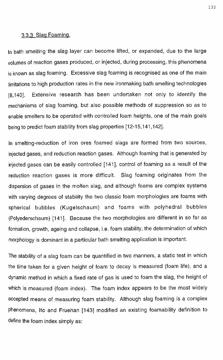
132
3.3.3 Slag Foaming.
In bath smelting the slag layer can become lifted, or expanded, due to the large
volumes of reaction gases produced, or injected, during processing, this phenomena
is known as slag foaming. Excessive slag foaming is recognised as one of the main
limitations to high production rates in the new ironmaking bath smelting technologies
[8,140]. Extensive research has been undertaken not only to identify the
mechanisms of slag foaming, but also possible methods of suppression so as to
enable smelters to be operated with controlled foam heights, one of the main goals
being to predict foam stability from slag properties [12-15,141,142].
In smelting-reduction of iron ores foamed slags are formed from two sources,
injected gases, and reduction reaction gases. Although foaming that is generated by
injected gases can be easily controlled [141], control of foaming as a result of the
reduction reaction gases is more difficult. Slag foaming originates from the
dispersion of gases in the molten slag, and although foams are complex systems
with varying degrees of stability the two classic foam morphologies are foams with
spherical bubbles (Kugelschaum) and foams with polyhedral bubbles
(Polyederschaum) [141]. Because the two morphologies are different in so far as
formation, growth, ageing and collapse, i.e. foam stability, the determination of which
morphology is dominant in a particular bath smelting application is important.
The stability of a slag foam can be quantified in two manners, a static test in which
the time taken for a given height of foam to decay is measured (foam life), and a
dynamic method in which a fixed rate of gas is used to foam the slag, the height of
which is measured (foam index). The foam index appears to be the most widely
accepted means of measuring foam stability. Although slag foaming is a complex
phenomena, Ito and Fruehan [143] modified an existing foamability definition to
define the foam index simply as:

133
1 = ^ 4 (32) Av vs
where h is the steady state slag height, Hf is the foam height, v is the linear gas
velocity, and v s is the superficial gas velocity. The stability of a foam cannot be
readily defined as an intrinsic property of a slag, but is a function of several factors
including temperature, bubble size and surface viscosity. A correlation was
developed by Jiang and Fruehan [144] for the foam index in bath smelting as:
1 = 1 1 5 ^ = (33) ** Y p a
where u. equals slag viscosity, p equals slag density and a equals slag surface
tension. Good agreement was found between pilot plant trial data and predicted
foam heights. Zhang [15] developed the correlation further relating foam index to
slag properties and bubble diameter according to:
1.2
Y = 1.83 — ^ (34) ^ 0.2 _,0.9 V '
o P D b
where Db equals the average bubble diameter.
The correlations for the foam index developed by Fruehan and his co-workers
[15,143,144] suggest that in general the foam index is approximately proportional to
the liquid slag viscosity, inversely proportional to the slag density and bubble
diameter, but independent of surface tension. However in contradiction, the work
conducted at Nippon Steel [12,145], experimentally showed that the slag foaming
height was approximately inversely proportional to slag viscosity, as shown in Figure
53, and surface tension as shown in Figure 54.
Figure 55 illustrates the effect of temperature on slag foaming, namely that the
foaming index is inversely proportional to the slag temperature. Slag foaming is also
affected by not only gas velocity but also gas type. Increasing gas velocity increases
the gas foaming height, as illustrated in Figures 56, 57 and 59.

134
0
©
•
X
Temp.
1573
1623
1673
1623
C a f V C a O
0.15-0.25
0.15-0.25
0.15-0.25
0.30-0.50
1.0 10 Viscosity (N- S/m2)
Figure 53. Relationship between slag viscosity and foaming slag height for a CaO-
SiOg-AlgOg-PgOs-T'^-MgO-MnO-CaFs-FeO complex slag [145].

250
200
150
1001— 400
Furnace: 100 kg
CaO/SiO2=1.0 =1.48
Al 203 = 11-30% MgO =7-25%
1600°C
log Po2 = -10.5
450 500 Surface tension (mN/m)
Figure 54. Relationship between slag surface tension and slag foaming height [12].

136
1.50
1800
Temperature, K 1900
Figure 55. Effect of temperature on foaming index for a CaO-Si02-AI203-FeO slag
[14].

1.50
1.00 1.50 Superficial Gas Velocity, cm/s
Figure 56. Effect of superficial gas flow rate on foaming height for a CaO-Si02-
AI203-FeO slag at 1873K [14].

138
e o SI
ET v X E a o
a
6
4
2
01
i i l
/ A r a o n
0 / Hvdronen
/ Helium
/ 1=1.8
/o
/ V,
/ V
/ - -" "
/ • ^ ^
/ ^ — / >"
/ • > ^ / •' S
/ -" <s
* I 1
1=0.82
1=0.5
i
2 4 6
Superficial Gas Velocity, cm/sec
Figure 57. Effect of superficial gas velocity and gas type on foaming height for a
CaO-Si02-CaF2 slag at 1773K [146].

139
If the gas velocity increases dramatically the physical properties of the slag change,
namely the stability, at high gas velocities the slag is considered as expanded rather
than foamed [142]. The effect of gas type on bubbling was extensively studied by
Zhang and Fruehan [146], it was found that decreasing mass flowrate decreased the
extent of slag foaming, as shown in Figure 57. Gas type has also been recognised
to effect the bubble morphology in the foam [12], in real bath smelting systems where
bubbles are generated at the slag-metal interface, schematically shown in Figure 58,
the bubbles have a Kugelschaum morphology. While experimental systems using
gas injection have often been observed to have Polyederschaum morphology. This
may partly explain the differences, as shown in Figure 59, between predicted and
actual foam volumes as measured in AISI bath smelting pilot plant trials [3]. Slag
foaming is also influenced by the FeO content of the slag, which in turn means that
the ore feed rate and degree of pre-reduction affect slag foaming [7,141]. Figure 60
shows that increasing feed rate increases slag foaming.
The most practical means to control slag foaming has been the addition of
carbonaceous material such as coke or coal char to the slag layer. This phenomena
has been examined both on a laboratory and industrial scale. It is known that
carbonaceous particles are non-wetting to slag, and as such destroy the bubble
lamella, the carbonaceous particle coalescing fine bubbles to form larger bubbles, as
illustrated schematically in Figure 61 [12,13]. Another possible mechanism is
postulated by Zhang and Fruehan [147] whereby the carbonaceous particles rupture
the slag film by rapid film thinning due to differences in the instantaneous and
equilibrium contact angles. Figures 62, 63 and 64 illustrate that increasing the
carbonaceous material content increases the extent of suppression, the effect of
which tapers out at 15-20% surface area coverage [147]. Slag foaming can also be
suppressed by decreasing, or regulating, the flowrate of injected gases [141],
however, this may have the disadvantage of reducing overall process efficiency due
to lower post combustion and reduction rates.

140
10mm
Slag
oo 0 O o
^o..nQB<>iipaQj!,fti?.i>.l : ; . : • •:•:• . : • . - : : • : • : • : • : • : • : • : • : • ; - : • : • : • : • • : • : • . ' . : • : • " .
i.r' • •
>a .an. i(? p o„fl. a ,Q ° „a0.. $ M * * • • : • : : • . ; : • : : : • • : . ; " • : ' . . ' : . : : : : • : • : ' •
«*1
Large bubble
Foam
Metal
Figure 58. Schematic diagram of bubble generation at the metal-slag interface, due
to reduction of iron, and subsequent foam growth [13].

16
J, 12
6 o 8
re
o 4
0 0 8 16 24 32
Off Gas Flow (m3/sec)
Figure 59. Predicted and process foam volumes measured from the AISI-DOE
smelting trials [3].
• ' -1 1 1 1
: Calculated S
s . i . i. .
- i —
•
i
1 ' J
m • •
•1" • j m
i t

142
.9. 4
£.3 E « o o *
« * -
^ 1
0 1 2 3 4 5 6 Ore feed rate (kg/min)
Figure 60. Effect of ore feed rate on slag foaming for a 1 tonne smelting vessel at
approximately 1500°C [13].
Coke/ slag mass ratio •0.10 AO.20
00.15 AQ.25
y-y

143
Carbonaceous material
Bubble Coalasced bubble o O,
O Foaming slag
Figure 61. Schematic diagram of the mechanism for suppression of slag foaming by
carbonaceous particles [12].

p o
E
s:
E TO O
E o
E o
Number o( particles (coka sphere, diameter =10 m m )
superficial gas velocity (cm/sec)
Number of particles (coal char, mean diamctcr=fi-10mm)
superficial gas velocity (cm/sec)
Figure 62. Effect of A) coke, and B) coal char particles on suppressing foam height
in a CaO-Si02-CaF2 slag at 1773K [147].

5
•B 4
S 3
0 0.1 0.2 0.3 0.4 0.5 0.6 Coke/Slag mass ratio
Figure 63. Effect of coke additions on slag foaming for a 1 tonne smelting vessel at
1500°C[13].
Ore feed rate

2.2
o OJ
X OJ T3 C
C
E o
• 3mm spheres
D 10mm discs
9 10mm spheres A coal char
O 6mm spheres
0.0 0.1 0.2 0.3 0.4 0.5 0.6
A /A particles crucible
Figure 64. Effect of carbonaceous material additions, as a function of surface
coverage area, on foaming index for a CaO-Si02-CaF2 slag at 1773K [147].

147
3.3.3 Reduction of Iron.
The smelting reduction of iron oxide can occur via several reactions, the predominant
reduction path being process dependant. In the AISI-DOE and DIOS type bath
smelting processes, i.e. deep slag processes, reduction of oxides by carbon
contained in iron droplets suspended in slag is predominant, while the bulk of
reduction in the Hlsmelt process occurs through reduction in the iron bath [9].
Reduction also occurs via char entrained in slag and at the metal-slag interface.
Katayama and co-workers [127,139] added molybdenum, as a tracer, to the iron bath
of a smelter, subsequent slag sampling during operation showed that 85-95% of the
iron droplets originated from the bath. Iron droplets in the slag were concluded to
originate from two sources, smaller particles (-0.5mm) from reduction reactions and
larger particles (+0.5mm) from the iron bath. It is evident that particle size is
dependant on operating conditions, using a 100 tonne smelter and approximately 2-3
kW/t bath agitation Ibaraki [127] determined the mean iron droplet size in slag was
2mm, as shown in Figure 65, similarly Belton and Fruehan [9], in a review of bath
smelting, reported that the major portion of droplets in bath smelting processes are in
the order of 2 to 10mm.
The distribution of iron droplets in slag is dependant on bath stirring intensity and
slag viscosity, in general the upper part of the slag layer contains less iron droplets
while lower regions are effectively a condensed iron zone. Ibaraki [127] determined,
by sampling, that the iron weight ratio in lower regions was variable between 30 to
80%, while in the upper regions was more constant at approximately 1 0 % , the
variation of droplet distribution is clearly shown in Figure 66. In a similar study
Katayama et al [148] found upper slag regions to contain 5 to 15wt% iron droplets
while lower slag regions contained 3 0 w t % or more, the amount of iron droplets was
found to increase by increasing stirring intensity of the bath. Iron droplet distribution

^f;
*-> E
C O
-4-*
"-o a o i_ Q _
80
60
40
20
-
—
cn LC
J
CD O ~*
7 CO in
CM — < CM
I o o
o o LO
* CM
CM
O O o
T CD o LO
Cumulative—
o o o O O CO o o t» CM rr co c 7 J o o o o o o o o o •—« CM •c
7
J o CO f-CO
Size of metal droplet ( # m )
Figure 65. Measured size distribution of iron droplets in bath smelting slag, for a 100
tonne smelting vessel with 2-3kW/t bath agitation from bottom blowing N 2 and top
blowing 0 2 [127].

149
O
\
0 20 40 60 80 100
Iron weight ratio ( w t % )
Figure 66. Variation of iron droplet distribution in a bath smelting slag layer, for a 100
tonne smelting vessel with 2-3kW/t bath agitation from bottom blowing N 2 and top
blowing 0 2 [127].

is also dependant on slag viscosity and stirring intensity, as shown in Figure 67
increasing intensity increases the distribution of iron droplets in the slag. Research
by Sommerville et al [149,150] showed, on a laboratory scale without agitation, iron
droplets were still present in the slag layer. However metallographic examination of
the droplets revealed a ferritic structure thus eliminating the possibility that they
originated from the iron bath, instead being a product of reduction.
The larger iron droplets, those ejected from the iron bath, have a sufficiently high
carbon content that they are molten at temperatures employed in bath smelting.
These droplets provide an interface for reduction in slag, it is well documented that
this is the dominant reduction mechanism accounting for approximately 5 0 % of
reduction [127,151], although it has been shown that the extent to which reduction
mechanisms are observed is dependant on experimental scale [148].
The reduction reaction between dissolved wustite and iron droplets in slag occurs via
a two step reaction where carbon monoxide acts as a gaseous intermediate, a
schematic representation of the reaction is shown in Figure 68. Based mainly on
research by Sommerville [149] and Belton [152] the overall reaction is now known to
occur according to:
(FeO) + C = Fe + CO(g) (35)
the two intermediate reactions being the reduction of dissolved FeO by CO at the
slag-gas interface (reaction 36) and the reaction at the gas-metal interface (reaction
37).
(FeO) + CO(g) = Fe + C02(g) (36)
C02(g) + C = 2CO(g) (37)

151
~ 1.0
« 0.8
0.6
0.4
0.2
Bottom bubbling gas
O Standard
* Standard x 2.1
20 40 60 80 100
Amount of metal droplets (wtX)
Assumed surface of slag layer
1.0 L
0 20 40 60 80 100
Proportion of iron metal in sample !wt%
Figure 67. Influence of stirring intensity on the iron droplet distribution in slag for a
100 tonne bath smelting reactor [148,139].
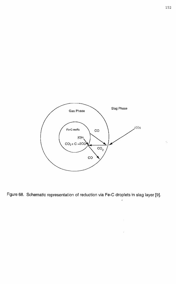
152
Gas Phase Slag Phase
,(0)s
Figure 68. Schematic representation of reduction via Fe-C droplets in slag layer [9].

153
A gas halo quickly develops around iron droplets after ejection from the iron bath,
gas agitating the slag in the intermediate vicinity, this effect is readily observed using
X-ray radiography techniques [151]. The halo is maintained around the droplet while
the reaction proceeds at a fast rate, the halo disintegrating once the reaction slows,
without the halo providing buoyancy the droplet descends through the slag layer to
the iron bath. It has been observed that droplets remain spherical and do not
fragment during reaction [151], containing some 1.5 to 2.0% carbon at the time of
descent back to the iron bath. The reduction of dissolved F e O by carbon in iron
droplets is characterised by 3 stages, a brief incubation period followed by a rapid
constant rate period and then a slow declining rate period. These different stages
were originally observed by Sommerville [149] and were later measured by Min and
Fruehan [151] who measured the flow rate of C O developed during the reduction of
Fe-C droplets in bath smelting slags, as shown in Figure 69.
The metal-gas reaction (reaction 36) is dominant in reduction of dissolved F e O in
slag by iron droplets, Min and Fruehan [151], using X-ray fluoroscopy, observed that
the slag-gas interfacial area w a s much greater than the metal-gas interface,
theoretical calculations have shown this to be a factor of at least 6 [9]. At an
industrial scale the total interfacial area of iron droplets in slag is considerable,
Ibaraki [127] calculated, using data determined from slag sampling, that under given
operating conditions with a slag weight of 20 tonnes the interfacial area was 2600m2.
Reduction rates were calculated using the interfacial area and were found to be twice
that of experimental observations, 46t-Fe/hr versus 23t-Fe/hr. Ibaraki postulated that
the difference was due to the inhibition effect of sulphur and a reduced interfacial
area due to gas coverage.
Min and Fruehan [151] concluded that the overall reduction rate was controlled by
gas-phase mass transfer in the gas halo, liquid-phase mass transfer in slag and
dissociation of carbon monoxide on the surface of the iron droplet. The rate of
reduction is dependant on wustite content of slag, and carbon and sulphur contents

Time (sec.)
Figure 69. Rate of reduction, as measured by C O flow rate, for a Fe-C droplet in a
CaO-Si02-AI203-FeO slag at 1673K [151].

155
of the droplets, the rate increases with increasing wustite and carbon contents but
decreases significantly with sulphur, the sulphur interfering with dissociation of
carbon monoxide [9]. For high sulphur contents that are expected in bath smelting
(>0.05wt%) the rate of reduction is given as:
Rate = k C 0 2 A m K 3 5 C (%FeO) (38)
where Am is the surface area of the droplets, K35 is the equilibrium constant for
reaction 35, C is a constant relating activity of F e O to % F e O , and k C 0 2 is the rate
constant for reaction of C 0 2 with carbon saturated liquid iron.
From the above discussion it can be seen that the rate of reduction can be increased
in several ways: increasing the slag weight; increasing the weight distribution of iron
droplets suspended in slag; increasing wustite content of the slag; and decreasing
sulphur content of the iron. The effect of sulphur content, F e O content, slag weight
and stirring intensity, on the rate of reduction are shown in Figures 70, 71, 72 and 73
respectively.
A typical means of promoting iron droplets in the slag layer is to bottom blow the
smelter vessel with nitrogen gas, gas agitating the bath sufficiently that more iron is
ejected into the slag layer. Hirata et al [137] found that not only did increasing
stirring power generate more iron droplets the temperature gradient across the slag
layer decreased, heat transfer being aided by increased circulation of the slag.
Temperature measurements have found that in general the slag and iron bath differ
in temperature by less than 30°C, although higher temperatures are commonly
measured in the upper part of the slag layer, this is thought to be due to entrainment
of hot reaction gases [127,139]. Hirata et al using a 10 tonne furnace found that for
efficient reduction bottom blowing of nitrogen was required as a quiescential bath
provided inadequate heat transfer and iron droplets for reduction, however the post
combustion ratio decreased. Similarly, increasing wustite content of the slag would

156
< Calculated
— i — < — i — • — i — • — i — • — i — • — i — > — i — • — i — r ~
10 20 30 40 50 60 70 80 90
1/[%S]
Figure 70. Rate of F e O reduction, experimental and calculated, as a function of the
sulphur content in iron droplets [151].

Figure 71. Rate of FeO reduction as a function of the FeO content in the slag as
measured by the generation of C O [151].

0.10
= 0.08 E
^ 0.06
0.04
ID O *-> E 5C. 0.02
o
•
5t
loot
o°0°^0
%°ooOo° °0 6b
Ka
E = 2 4kW/t
1450 •«. 1500°C
K = Ka + (Ws/A)-Ks
0.5 1.0 1.5 2.0 2.5 3.0 Ws/A (t/m2)
Slag Weight (t)
Figure 72. Relationship between slag weight and reduction rate in A) a 5 and 100
tonne bath smelting vessel [148], and B) a 100 tonne bath smelting vessel [127].

tv o
0.10
0.09
0.08
0.07
0.06
0.05
0.04
0.03
0.02
0.01
0
_
1450 -• 1500°C
Amount of slag : 0.2 -- 0.7t
^ ^<^
*f
**" ^
" - ^ ^ ^ O 0 0
---c> o° 0o ° ^
~CD O _- - ^ - CD ° ° - - - "
_0 - — — 5t furnace
i i i 1 1 1
0 2 4 6 8 10 12
Stirring intensity (kW/t)
14
Figure 73. Influence of stirring intensity on reduction rate for a 5 tonne bath smelting
vessel [148].

160
decrease the process yield, while reducing sulphur content is hindered by availability
of carbonaceous material with low sulphur contents [9].
In bath smelting carbonaceous material is used not only to suppress slag foaming,
but contributes to reduction and can accelerate heat transfer. Typically, the weight
ratio of char in slag is between 10 and 4 0 % , Ibaraki and co-workers [127] found char
weights were scattered, finding it difficult to determine a relationship between char
concentration and slag depth, as shown in Figure 74. Katayama et al [139] were
unable to determine with confidence the distribution of char in slag due to the
difficulty of sampling. Fluid dynamics was used to predict that particle density would
be greater in outer and upper regions of the slag layer. Figure 75 illustrates the
predicted flow patterns and carbonaceous material distributions for a 100 tonne
smelting vessel. It has also been observed that a portion of char exists during
operation in the gas free space above the slag layer. Predicted and experimental
distributions are independent of carbon source, i.e. coke compared to coal char,
however, it has been observed that as result of cracking, from rapid heating, that coal
char size is smaller than coke.
A gas halo is also observed with reduction via char in slag, however unlike reduction
via iron droplets no significant incubation period has been observed [9]. The reaction
of carbon dioxide, reaction 37, with carbon is complex and determines the overall
rate of the char-slag reduction reaction [9], being dependant on solid sample size,
temperature, gas composition and pore structure of the carbon, although it is now
thought that the reaction is controlled by F e O mass transfer [3]. O n an industrial
scale the effects of different types of carbonaceous material, particularly on the
reduction rate, remains unclear [148].
The rate of reduction via the char-slag reaction has been shown to be dependant on
the FeO content of the slag, slag properties such as viscosity, and the carbonaceous
material content of the slag. Fruehan [7] found that increasing the F e O increased

o
1 -
0.8-
0.6-
0.4-
0.2-
0 -
O
O
o oo o
o
O
_ ° c
9)
o
-4-
o
o
9o >
o
1 1 1 0 10 20 30 40 50
Char weight ratio (wt%)
Figure 74. Distribution of char in the slag layer of a 100 tonne smelting vessel [127].

200 mm/sec
Flow pattern Distribution of carbonaceous meterials
Figure 75. Predicted fluid flow and char distributions in a bottom and top blown 100
tonne bath smelting vessel [139].

163
the rate of reduction of F e O from a bath smelting type slag as shown in Figure 76,
similarly, as observed by Nippon Steel in 1 and 5 tonne smelting trials increasing the
coke content increases the reduction rate, as shown in Figure 77. While reduction
rates have been found to be maximum in slags with the lowest viscosity, Figure 78
shows rate data derived from rotating disk tests at 1450°C, maximum reduction
occurring at a viscosity of approximately 4 poise [153].
Ibaraki [127] calculated that the interfacial area for char in slag was considerably
greater than the interface of iron droplets in slag, for a 20 tonne slag weight a char
interface of 11000m2 was calculated. Although the reaction rate of iron droplets is
five times greater (per area) than char the contribution of char overall is significant
due to its shear interfacial size. High sulphur contents in iron droplets can result in
the char-slag reaction being dominant, this would be associated with increased
energy requirements since the endothermicity of the char-slag reaction is 3 0 %
greater than reduction via iron droplets [9].
Katayama et al [148] estimated, using data from 5 and 100 tonne smelting trials, the
amount of reduction due to the different mechanisms, Table 17, and found that the
contribution of the individual reduction mechanisms in the total reduction was
dependant on process scale and slag volume. Increasing scale and slag volume
increased the proportions of reduction via char-slag and iron droplet-slag interfaces.
For bath smelting processes where the majority of reduction occurs in the slag layer
the overall rate of reduction is given as [7]:
Rate = (k^A + kcsWc)(%FeO) (39)
where ksm is the rate constant for the slag-metal reaction, kcs is the rate constant for
the char-slag reaction, W c is the weight of carbonaceous material in the slag and A is
the surface area of the bath. From the above equation it can be seen that increasing
the FeO content in the slag and the char weight will increase the reduction, this is

164
C O evolution vs Time
OJO «0J) 120i> '""> 2*)J0 300/) seo.o «ao ^aao
Figure 76. Effect of F e O content in a CaO-Si02-FeO slag on the rate of reduction via
carbon [7].

165
0.03 -
0 50 100 150 200
Weight of coke (kg/m2)
Figure 77. Effect of coke content in slag on the rate of reduction [7].
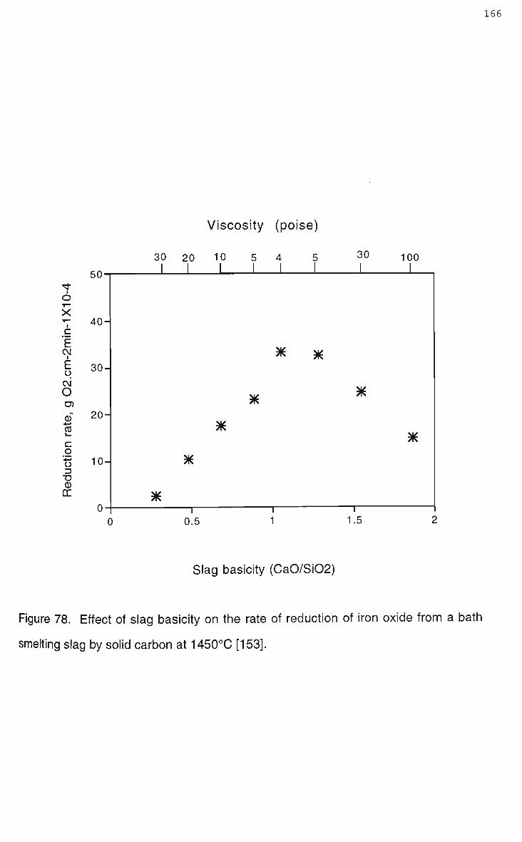
166
Viscosity (poise)
i
o ><
CM •
E o c\i O
C g o D TJ (D DC
C fl bO-
40-
30-
20-
10-
0
30
I
*
20 |
*
I
10
I
K
5
I
K
4
I
*
I
5
I
*
30
I
*
i
100
I
*
0.5 1.5
Slag basicity (CaO/Si02)
Figure 78. Effect of slag basicity on the rate of reduction of iron oxide from a bath
smelting slag by solid carbon at 1450°C [153].

167
Table 17. Proportion of Reduction at Interfaces [148].
Proportion of
Reduction at the
Iron Bath-Slag
Interface
0.70
0.55
0.37
0.45
0.34
0.005
Proportion of
Reduction via the
Iron Droplet-Slag
Reaction
0.18
0.27
0.37
0.45
0.33
0.40
Proportion of
Reduction via
the Char-Slag
Reaction
0.12
0.18
0.26
0.10
0.33
0.595
Remarks
5t, low slag
5t, high slag
100t
10Ot, large coke
100t, increased coke
170t, Fruehan [154]

168
shown in Figure 79 for experimental and predicted rates for the AISI-DOE bath
smelting processes.
For processes where oxide/ore is injected directly into the iron bath, such as Hlsmelt,
it is reasonable to expect the dominant reaction will be reduction via the iron bath.
Extremely high reduction rates are encountered for both hematite and wustite; the
absence of gas nucleation during reaction led Belton and Fruehan [9] to suggest that
reduction occurs by direct reduction where iron becomes supersaturated with
oxygen, desorption at the iron bath-slag interface by carbon monoxide occurs via the
reaction:
C + O = CO ( g ) (40)
Although Krishna Murthy and Elliot [134] during dissolution/reduction experiments, as
previously described, did observe significant gas evolution.
Belton and Fruehan [9] from their review of previous studies on the reaction between
iron oxides and liquid iron melts conclude that potential reduction rates in the iron
bath are sufficiently fast that the limiting step to processing will be heat and mass
(carbon) transfer to the bath and that although maximum reduction rates are known,
the effect of sulphur and gangue contents encountered in real systems are yet to be
determined.
3.3.4 Function of Carbonaceous Material in Bath Smelting.
Carbon plays an essential role in bath smelting of iron oxides, in general carbon is
consumed by reduction, carburisation, combustion and is lost through dust carry
over; the path taken by a carbonaceous material depending on the manner in which
it enters the process stream. Carbon is not only added because it is a reductant but
also as it provides thermal energy to the process. Carbon is supplied to the process

1.2 i 1 ] r
0 2 4 6 8 10 (%FeO)
Figure 79. Predicted and experimental rates of reduction for varying FeO contents in
the AISI-DOE bath smelting processes [3].

through the addition of a carbonaceous material fed either to the slag layer or
injected into the iron bath. Injection into the bath involves fines only, while the slag
layer can accommodate either fines, lumps, or carbon entrained with ore in pellets.
Consumption of carbonaceous material is complex, involving decrepitation and
pyrolysis.
Fine carbonaceous material, generally coal, injected into an iron bath rapidly heats
under flash like conditions resulting in decrepitation and pyrolysis, carbon can then
either carburise the bath (dissolution) or combust with any oxygen present,
effectively reduction of dissolved FeO. The volume of gas generated is considerable,
gas from pyrolysis being initially rich in higher order carbons, although rapid thermal
cracking results in evolution of more stable gases such as CH 4 , while gas from
combustion is rich in carbon monoxide.
Although pyrolysis is actually a series of multiple reactions, all with different rate
constants, it is often expressed simply as the rate of degassing being a temperature
dependant first order reaction [155]. Degassing is accompanied by the generation of
a gas halo, as schematically shown in Figure 80, which is thought to evolve when
degassing has reached approximately 5 % [155]. Orsten and Oeters [155] developed
an empirical relationship for degassing of coal particles in an iron bath at 1500°C,
finding that the degassing time could be expressed as:
tg = f dp1-5 0.05 < dp < 0.8mm (41)
where tg is the degassing time in seconds, f is a constant dependant on coal type
(typically between 1.02 and 1.14), and dp is the particle size. Illustrated in Figure 81
is the influence of coal type and particle size on degassing, increasing size
increasing degassing time, while increasing volatile matter (VM) decreases
degassing time. The extent of gasification that occurs in the metal bath can therefore
be seen to be dependant on particle size, volatile matter, and length of time in the
bath, i.e. plume velocity and bath depth. Analysing the work of Wright and Baldock

171
melt*
volatiles
coal particle
Figure 80. Schematic diagram of a coal particle degassing in a melt, gas evolution
being sufficient to create a gas halo around the degassing particle [155].

172
o E a —» o > -o o a a es 01 o T3
I .u -
0.8
0.6
0.4
0.2
n -
0.1
,
1
1 °'2
'
/0.4 / 0.6
•
/ d, [mm]
/ U
iron bath
T=1773K
0.2 0.4 0.6
time t [s]
0.8 1.0
u e
c o n) U
1.0
0.8
0.B
0.4
V
"D 0
-i 1 • 1 '
bituminous co-tls
1 : 15.7 55 volatile matter
2 : 24.8 '/.
3 : 37.9 '/.
0.2 0.4 0.6 0-8
particle diameter dp Cmm]
1.0
Figure 81. Influence of particle size and volatile matter on the degassing of individual
coal particles in an iron bath at 1773K [155].

[156] it is clear that for the large particles used in their study, +180u.m,
degassification would not have been completed during the initial rise through the iron
bath, but must have been completed either while floating on the surface or in the
bath if entrained.
Wright and Baldock [156] found that over a wide range of conditions the rate of
dissolution of graphite equalled the rate of injection up to approximately 8 5 % carbon
saturation, particle size appeared to have little effect on the ability of dissolution to
match the injection rate nor did varying the bath temperature between 1400 to
1500°C. The sulphur content of the bath was determined to have a retarding effect
on dissolution, at a sulphur content of 0.1% dissolution kept pace with injection up to
8 7 % saturation while at sulphur level of 1.0% injection outpaced dissolution at only
6 2 % saturation. The use of graphite should be considered as "ideal" dissolution
behaviour, non-graphitic carbons being markedly effected by their volatility and the
concentration of sulphur in the iron bath, the retardation effect of sulphur being
strongly dependant on the nature of the carbonaceous material [9].
Atypical injected coal particle (0.1mm diameter, bath at 1500°C and 3.5%C) can be
expected to dissolve in about 2 seconds, calculations suggest pyrolysis is unlikely to
significantly slow dissolution [9], larger particles (+2mm) will survive to the bath
surface, the stirring intensity of the bath then effecting the dissolution time [157].
However, the volatile content of the carbonaceous material does effect the amount of
carbon that is consumed by carburisation. Carbon absorption by the bath depending
on the amount of fixed carbon rather than total carbon injected, Figure 82 shows
carbon absorption behaviour as well as the retardation effect of sulphur, compared to
the total carbon injection rate.
In regards to the retardation effect of sulphur on dissolution, the comments of Orsten
and Oeters appear relevant [155]. Although low sulphur levels are desirable it should

174
C o
"5 i _
"o in i
O o c o ~o o 1_
LL
1 r — r
0-8
0-6 .-rf.-B
O-^'x-'x
T T TOTAL CARBON INJECTION RATE
o .n"'D\ D
Q.-n o-e-
X X X x
0-2
0
FIXED CARBON INJECTION RATE
0
o 0 02% S D 0-32% S X 0 -64% S
_L l j_
U 8
TIME, min 12 16
Figure 82. Influence of sulphur on retarding the absorption of carbon into an iron-
carbon melt at 1723K using a 32% VM coal [9].

175
be kept in context that the dissolution of carbonaceous materials into iron baths are
so fast that other factors are likely to have a far greater influence.
The majority of bath smelting processes feed carbonaceous material into the slag
layer, injection into the iron bath being used as an auxiliary source of carbon.
Feeding carbon to the slag layer provides greater operating flexibility in that carbon
can be fed as fines, coarse or mixed with ore in pellets. Similar to injection into the
iron bath the reaction of carbon in the slag layer is dependant on the nature of the
feed material. Upon entering slag a carbonaceous material undergoes decrepitation
and pyrolysis, with smaller particles being carried away by the off gas stream [139].
Depending on temperature a given amount of carbonaceous material circulates in
the slag, circulation being aided by gas bubble pickup which floats carbonaceous
material to the top of the slag, bubbles are lost allowing the carbonaceous material to
descend into the slag again, pilot plant trials found the amount that circulates in the
slag is in the order of 20-30 vol% [139,148].
One of the interests in developing the new ironmaking bath smelting processes is the
potential to use cheaper low rank coals. Extensive research into the effects of coal
rank on devolatilisation have been performed by Sampaio [158], while the effects of
coal rank on overall production have been investigated by both the DIOS and AISI
bath smelting research teams [6,8]. Coal devolatilisation rates were found to be
relatively independent of coal type, but as shown in Figure 83, influenced by particle
size [158]. Similar rates were measured for devolatilisation in the gas phase as for
those fully immersed in molten slag, immersion in the slag generating a gas halo.
For the large particles used in Sampaio's study, 3 - 9 m m , devolatilisation was found
to be heat transfer controlled, the rates being mainly influenced by the rate of heating
and particle size. Evident from both the experimental and modelling work of
Sampaio is that depending on particle size it is possible for low rank coal particles to
reach the slag layer still containing significant amounts of volatile matter.

176
HDE, 3 mm ID, 3 mm ID, 6 ram HDE, 6 mm ID, 9 mm
- - - - - - HDE, 9 mm
15 20 25
Figure 83. Influence of coal particle size and volatile matter on the fraction of
devolatilisation. Samples fully immersed in a CaO-Si02-CaF2 slag at 1520°C; LD -
low V M coal, H D E - high V M coal [158].

177
Takahashi et al [16] performed a heat balance for bath smelting so as to predict the
influence of volatile matter on overall coal consumption. Assuming that it is only the
fixed carbon portion of coal that results in reduction and carburisation it was
predicted that as the volatile content increased the overall amount of coal consumed
increased as well, as shown in Figure 84. Operation of the DIOS bath smelting pilot
plant has, at an industrial scale, showed the influence of coal type on operating
performance and practise. In essence the greater the volatile matter content of the
coal, the more coal that is required for smelting. Typical data from the DIOS trials
found with low V M coal production ran at 23.5t/hr consuming 780kg/t of coal, while
high V M coal saw production decrease to 20.8t/hr consuming 949kg/t of coal [6].
Dust carryover is also effected by the volatile matter content of the coal. Carbon dust
losses were reduced from 5.4% to 2.3% by changing from high V M coal to coke,
while operating the smelting vessel at increasing pressures reduced dust losses from
16.6% to 3.4% [16].
Carbon type also effects bath carburisation, Katayama et al [139] investigated bath
smelting using both coal and coke and found that the rate of carburisation decreased
with coal and that the overall carbon content of the bath was less. Coal, having a
higher volatile content, tended to decrepitate faster and had a lower wetability than
coke, resulting in a less circulation of coal in the slag. Because bath carburisation
was found to be dependant on contact between iron droplets and carbonaceous
material in the slag, the benefits of suppressing coal fragmentation have been
recognised as a potential means of increasing the circulation of coal in the slag layer,
and therefore the rate of bath carburisation.
3.3.5 Post Combustion.
In bath smelting reduction of iron carbon is oxidised to carbon monoxide, the reaction
generating 1.4 kWh/kg of energy. Importantly a further 5.8 kWh/kg can be generated

1000
OX)
o
I 5 0 0
o o 03 O
o
Pre-reduction degree i 15 % Pre-heating temperature: 800 °C
OD 1\ PC
CC] Heat loss
50 % 90 % 4.5 % 100 Mcal/THH
0
Coal consumption calculated from heat balance
kg-FC/Nm3-02
0.20"
, Contour [of F C R
^ /
io
J^TW
Reduction of ore
A
A /
*.
20 VM (%)
30 40
Figure 84. Influence of volatile matter content of coal on overall coal consumption; A
coal consumption by reduction, • additional coal for carburisation, O coal required
for heating, reduction and carburisation, i.e. total coal requirements [16].

179
if the carbon monoxide is completely combusted, shown in Figure 85, this can be
achieved externally by using the gas to generate electricity, the cost effectiveness
being site dependant [11], or by postcombusting within the smelting vessel.
Postcombustion not only provides heat to a process, but reduces air emission
problems and excessively high baghouse temperatures. In bath smelting processes
typically 40-50% of the carbon monoxide and hydrogen produced are post
combusted, post combustion being achieved by injection of air or oxygen into either
the foaming slag layer or in the gas space above the bath. Figure 86 schematically
shows the two approaches to postcombustion. Post combustion has been
extensively studied both theoretically [159-161] and experimentally [6,16,137,162],
the fundamentals being comprehensively reviewed by Oeters and co-authors
[10,125]. It is generally recognised that a high postcombustion ratio is critical for
bath smelting processes, however the difficulty is to simultaneously achieve efficient
heat transfer rates [9]. The post combustion ratio is calculated as follows:
(%C0j + (%H90) Post Combustion Ratio (PCR) = ( ^ l , ^ ^ ^ ^ ^ ) * 100 (41)
where the postcombustion reactions are:
0 2 + 2 C O = C 0 2 (42)
0 2 + 2 H 2 = 2 H 2 0 (43)
Post combustion is markedly affected by the amount of top and bottom blowing, an
increase in stirring intensity via bottom blowing decreases post combustion, although
reduction rates and heat transfer efficiency increase [139]. Pilot plant trials of the
DIOS process found that by increasing the stirring intensity up to even moderate
levels the post combustion ratio was severely reduced, as shown in Figure 87
[6,138]. This was also observed in Hlsmelt 10 tonne pilot plant trials where

180
0 20 40 Degree of
60 80 100 (%)
Figure 85. Heat generated from combustion of C and subsequent additional heat
from postcombustion of CO [163].

iron ore oxygen or j pre-heated air
oxygen or pre-heated air
metal and slag droplets
t t T t * coal
(oxygen)
slag
metal
iron ore | oxygen
flame
foamy slag
metal droplets
metal bath
t t t t t coal
(oxygen)
Figure 86. Postcombustion approaches, A) postcombustion in gas space above
bath, and B) postcombustion within the foaming slag layer [125].

182
O
CO
CD > O 1
CO
o to =5
C o
g
cfl
c o to
E o o
50 -
" '5 40 -
M 30-
20 -
CO
o Q- 10
0 0 1 2 3 4 5
Relative bottom gas flow rate (-)
100 £ >,
o
90 .§ CJ »»—
- 80 fe CD CO
c CO - 70 : co CD
50
CT40
g i_
c o CO •D
£ o o m o 0_
30
20
10
-
-
-
-
_
Ogg - %
I I Top blowing oxygen
10000-11000 Nrrf/h
6>\
^ T Coal: High volatile matter coal, +1mm
Lance height from metal surface: 1.09—2.01 m
• E r :
1 2 3 4 Bath agitation energy (kW/t)
Figure 87. Influence of A) bath agitation energy on postcombustion, and B) relative
bottom gas flowrate on postcombustion, heat transfer efficiency and dust carryover.
Experimental data from DIOS research program [138,6].

183
without bottom blowing postcombustion was 7 5 % , increasing oxygen injection to
1700Nm3/hr reduced postcombustion to 2 5 % as shown in Figure 88 [161].
Excessive bottom blowing promotes iron droplets to upper regions of the slag layer,
droplets then readily reacting with not only blown oxygen but also any combusted
gases. The de-post combustion reactions being:
C 0 2 + C = 2 C O (44)
H20 + C = H2 + CO (45)
Both of the de-postcombustion reactions are endothermic, that is they absorb energy
out of the system, kinetically reaction 45 is much faster than reaction 44, as shown in
Figure 89 sulphur retards both de-postcombustion reactions [3].
Apart from controlling bottom blowing and increasing the depth of the slag layer post
combustion can also be increased by careful top blowing practices [16]. Ideally
oxygen should only be blown into upper regions of the slag layer where distribution of
the iron droplets is minimal. If oxygen is injected too deep into the slag layer post
combustion decreases due to oxygen decarburising the iron droplets. Experimental
data from the AISI bath smelting program showed that increasing the gap between
the oxygen lance and the slag bath resulted in an increase in postcombustion, as
illustrated in Figure 90 lance positioning greatly effects the attainable degree of
postcombustion [8]. The greater the reaction and intensity of the top blown oxygen
with the slag layer the smaller the size of the iron droplets in the slag, smaller
droplets decarburising faster, as shown in Figure 91 [161]. The DIOS research
program [6] found that optimum conditions could be achieved by combining top and
side blown oxygen, together with bottom blown nitrogen, operating the smelting
vessel under pressure was also found to increase the postcombustion ratio [138].
Post combustion is also affected by the volatile matter content of carbonaceous
material used in bath smelting, pilot plant trials have shown that coals even with

184
0 500 1000 1500 Bottom Oxygen Injection Rate (Nm3/hr)
Figure 88. Influence of bottom injected rate of oxygen on postcombustion, predicted
and experimental data, for the 10 tonne Hlsmelt pilot plant [161].

100
cs to
13
a rf
O r-H
X
10
1 -
0.1
_
-
=
-
-
-
1 1 1
Fe-C Melts sat.
T=1873°K
l l 1
1 1
^ — ^ _
C ° 2
1 1
-
-
1
-
—
-
-
0 0.005 0.01 0.015 0.02 0.025 0.03
[mass pet S]
Figure 89. Comparative rates of reaction for C 0 2 and H20 with carbon in iron melts
at1873K[3].

186
50
45
£ 40 a a w 35 a
a J 30 125
2 20 a a. 15
10 -25
-+-25 50
Lance gap (cm)
75 100 125
Figure 90. Influence of oxygen lance position, relative to slag bath, on
postcombustion for the AISI bath smelter [8].
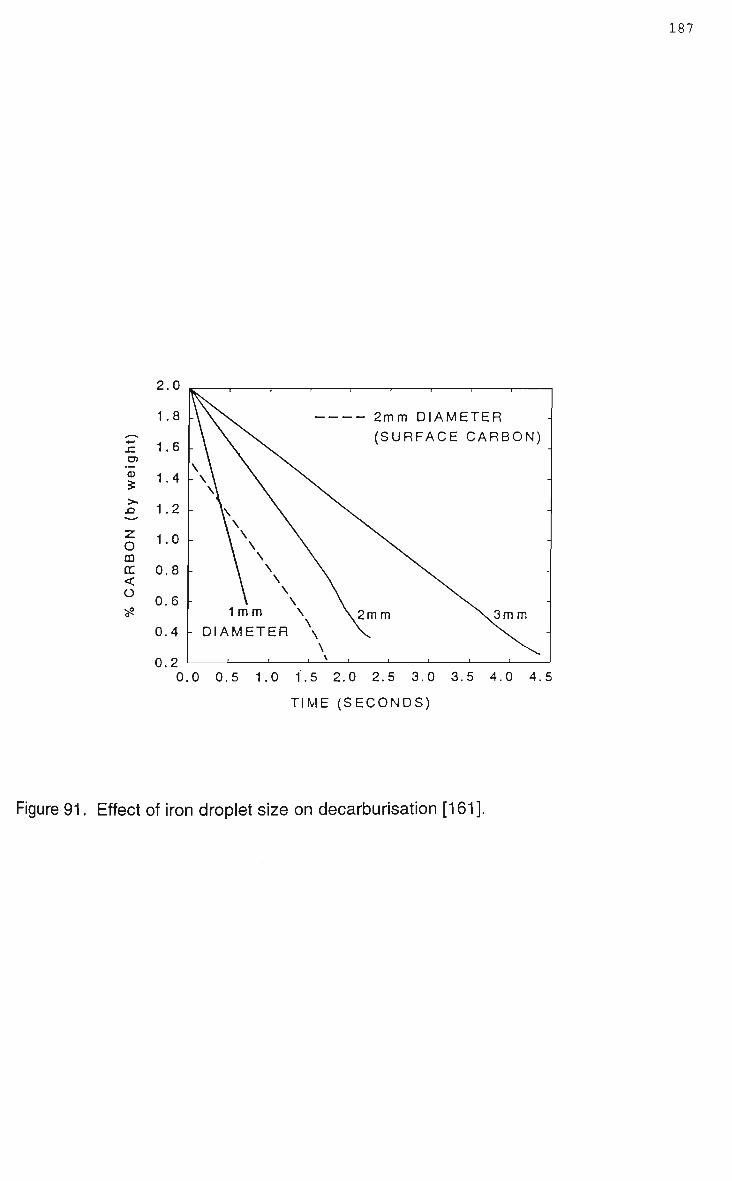
187
2.0
1.8
1.6
1.4
1.2
1.0
0.8
0.6
0.4
0.2
1 mm - DIAMETER
2mm DIAMETER (SURFACE CARBON)
,2m m 3mm
.0 0.5 1.0 i.5 2.0 2.5 3.0 3.5 4.0 4.5
TIME (SECONDS)
Figure 91. Effect of iron droplet size on decarburisation [161].

188
medium volatility can limit the post combustion attainable [9,16,127], the hydrogen
content of a medium volatility coal being in the order of 2 0 % . In general as the
volatile matter increases heat transfer efficiency increases, however as hydrogen has
a lower molar heat of energy for combustion compared to carbon the post
combustion ratio decreases resulting in a net increase in coal consumption. Figure
92 depicts predicted and experimental data of the influence of volatile matter on
postcombustion, heat transfer efficiency and coal consumption [17,148].
The control of post combustion is allied with many of the critical processes in bath
smelting, particularly heat transfer, reduction rate and dust generation, Figure 93
illustrates key operating parameters identified as being important to achieving
efficient postcombustion [16]. Considerable research, from different bath smelting
programs, have demonstrated that increased post combustion and heat transfer
rates can be achieved by controlling top and bottom blowing, slag depth, the amount
of carbonaceous material circulating in slag, feed rates of raw materials, and the
volatile matter content of the coal [9,127,139].
3.4 Bath Smelting Processes.
The worldwide push to develop a technology for producing iron that overcomes
inherit disadvantages of the blast furnace route has resulted in development of
numerous bath smelting processes. The rationale behind development of the new
technologies have been covered in numerous reviews on bath smelting [10,125,164],
as outlined by Fruehan [7] the incentives for pursuing new ironmaking technologies
are:
- Elimination of coke plants and subsequently the need for coking coals
- Possible elimination of sinter plants

189
- o - ,
10°i 0*0 o —^•y<*>» .. ,0 0
50
o\
TI*
\0
• \ a 3 \„ /A \
VM36.53
V»/
\
o o 1 •» jp % \
VM21.7J
VM 36.5% VM 21.7% Coke
• 9 O
50
PC (
Coke
100
o 700
Coals
A 4.2% H (Low V.)
B 5.2% H (High V.)
I J_
PCR (%)
Figure 92. Influence of volatile matter in coal on A) postcombustion and heat transfer
efficiency, and B) postcombustion and coal consumption [148,17].

190
jQptimization of I oxygen lance | ^ ^ r
• Double flow lance • Ultra-soft blowing
Post-combustion I in slag layer
• Keeping slag level high
• Control of lance height
Intensifying bath stirring
Optimization of feeding rate of raw materials
• Depression of coal carry-over
• Control of coal feeding rate
Smelting Reduction Furnace
Figure 93. K e y factors identified b y the D I O S research p r o g r a m a s being essential
for efficient post combustion [16].

- Lower capital costs
- Lower operating costs
- Economic viability at a smaller scale
- Production flexibility.
The current status of individual processes is that development is at various stages,
although many are considered to be at an advanced development stage with semi-
commercial and commercial operating scales [165]. A review by McAloon in 1994
[166] concluded that it was probably still too early in the development of many
processes to make a fair comparison as to which was the best technology. Although
there has been criticism [110] levelled at the lack of commercialisation, particularly
given the expense of development, in reality the adoption of any new technology is
not instantaneous [49]. Commercial acceptance of bath smelting technology may
take time, particularly given the worldwide level of capital invested in existing
traditional iron and steelmaking. A major reason given for companies failing to
pursue commercialisation of bath smelting processes is conservatism [11],
companies figuring into the capital costs a technical risk factor which offsets technical
or cost advantages the process may have otherwise had.
The two main distinct groups of bath smelting processes which have evolved are;
melter-gasifier reduction processes such as Corex; and in-bath smelting reduction
processes such as DIOS and Hlsmelt [89]. The different approaches to producing
iron is reflected in Figure 94 which compares the postcombustion ratio and
prereduction utilised in several bath smelting processes.

192
90
80--
c o •4-<
o
CI) i_
a) i—
Q.
70
60
50
40
30
20
10
Corex Jupiter
AISI-DOE DIOS
CCF
:M •vm
LRP
Hlsmelt
^ — i — i — r -10 20 30 40 50 60 70 80 90
Postcombustion (%)
Figure 94. Comparison of prereduction and postcombustion for several bath
smelting processes, adapted from Oeters et al [125].

193
3.4.1 Corex Process.
The Corex process was conceived in the late 1970's as a means of producing iron in
face of increasing gas prices and diminishing coking coal resources [168]. Currently
several plants are operated at a commercial scale, at ISCOR in South Africa a plant
(C-1000 unit) with a capacity of 300000 t/yr has been operating for several years,
while a larger plant (C-2000) has been built by Pohang Iron and Steel in South Korea
operating at 600000 t/yr. As of 1996 the original plant at ISCOR was operating at
10% over capacity (330000 t/yr) while several other plants were being built in India
and Korea [169]. It is this successful commercial history that is considered one of
the major assets of the Corex process. Distinct features of the Corex process are
the volume of unburnt gas produced and that separate reactors are used for
reduction and melting, a schematic diagram of the Corex process is shown in Figure
95.
Coal is fed into the melter gasifier, which operates under pressure, the upper regions
of the reactor being at temperatures of 1000 to 1200°C results in rapid drying and
degasification of the coal. Typical operating practise is 1100-1200 kg coal per tonne
of hot metal [169]. Because of the high temperatures in the upper part of the melter
there is complete thermal cracking so that no tar or benzene type hydrocarbons are
produced [170]. Carbon being oxidised to carbon dioxide then reacts with free
carbon according to the Boudouard reaction to form carbon monoxide, commercial
grade oxygen being fed into the reactor at a rate of 618m 3 per tonne of hot metal
[169]. The reaction generates reducing gas and also liberates heat from the coal
required for melting. The gas being in the vicinity of 1600 to 1700°C is too hot for the
reduction shaft furnace, cooling to 850 - 900°C is achieved by passing the gas
through a cooler and a cleaner. A typical gas composition from the melter gasifier is
65-70% CO, 20-25% H 2 and 2-4% C 0 2 .

194
Iron Ore
Coal/Lime
(-
Legend 1 Melter Gasifier 2 Reduction Shaft Furnace 3 Coal Feed Bin 4 Hot Dust Cyclone 5 Gas Cooler 6 Top Gas Cooler
Top Gas
1^-6
Export Gas
Reduction Gas
®*H)Ls~ 4 t
Raw Gas Cooling Gas
Figure 95. Schematic diagram of the Corex process [171].

195
The reducing gas, after cleaning for dust particles, is fed into the reduction shaft
furnace where reduction occurs counter-current as gas ascends through the burden
material. Sized, pelletised, or lump ore is fed using a lock-hopper system into the
reduction shaft with limestone and dolomite. Depending on raw feed material and
operating conditions typical metallisation rates are in the order of 9 5 % [168], sponge
iron being continuously fed (800 to 900°C), with carbon contents of 3 to 6%, into the
melter gasifier, were final reduction and melting occurs. The iron quality being
comparable to that produced through a blast furnace using similar feed material
[170]. Dust collected from the melter-gasifier unit, using a hot cyclone, is recycled to
the melter-gasifier, being pneumatically charged into the molten iron layer.
Apart from iron the other main product from the Corex process is export gas from the
reduction shaft, since post combustion is not utilised the off gas is rich in combustible
matter and lends itself to power generation [165]. Low hydrogen (apart from
methane -1%) and low nitrogen levels (-2.8%) in the export gas means, that apart
from generating electrical power, the gas would be suitable for synthesis of
methanol. Estimates put production of methanol, under normal operating conditions,
at approximately 2.5 barrels per tonne of iron [172]. As of 1996 the C-1000 unit at
ISCOR was generating typically 81000m 3 of export gas per tonne of hot metal [169].
Claimed advantages of the Corex technology include low S 0 2 and N 0 2 emissions;
operating flexibility, particularly the wide range of coals which can be utilised,
because of the separate reactors; ease of operation; and low capital and production
costs [169]. Capital and operating costs are reported to be 20-30% less for Corex
than a blast furnace [168,169,171], the operating costs including a significant credit
for the export gas [166].
Although the Corex process is undoubtedly the most industrialised alternative
ironmaking process it does have its limitations. Crucial operating parameters and
limitations of the process were revealed during commissioning and the first two years

196
operation of the C-1000 unit at ISCOR [173]. It was recognised that it was essential
to clean dust from the melter-gasifier off gas before it passes into the reduction shaft.
Characterisation and modelling of burden in the reduction shaft found that dust fines
become entrained in the burden reducing bed permeability, the dust concentration
predicted to be dependant on burden velocity [174].
Control of ore size distribution in the reduction shaft also greatly effects operating
performance, poor size control causing complete stoppages in the first and second
operating campaigns [168]. It is this need for size control, and the inability to feed
fines, that is viewed as one of the weaknesses of the process. Currently being
investigated are the effects of using fine ore injection through the dust recycling
system [175]. Recognition of the feed limitation of Corex m a y explain the
collaboration between Posco and Voest-Alpine Industrieanlagenbau (VAI), the
developers of Corex, to develop a new process, which uses ore fines, called Finex
[176]. High silica and alumina ores also present problems in the reduction shaft,
greater additions of limestone and dolomite are required and larger volumes of gas
are used for reduction [173]. Coal suitability also does not appear to be as broad as
claimed, it is apparent that careful blending of coal is required to balance the fixed
carbon and volatile matter content, and also to minimise the sulphur content
[168,169]. Refractory wear, particularly in the reduction shaft, has been raised as a
weakness [173], as is the overall plant availability. In 1990 plant availability was 85-
90 % [171] and by 1996 had been improved to 9 3 % [169], which is still lower than a
modern blast furnace.
Evaluating the economics of the Corex process is far more involved than the details
provided in technical literature, although Corex is claimed to offer potential savings of
20-30% [169], it is apparent that it requires large volumes of cheap oxygen [125] and
an economic use for the export gas such as electricity generation. A more recent
development being the plan to use the export gas, after removing C 0 2 , for the

197
production of DRI-HBI. It is estimated a typical C-2000 Corex unit would generate
sufficient gas for a 800000 tpa DRI-HBI plant [169],
3.4.2 DIOS Process.
The Direct Iron Ore Smelting process (DIOS) was conceived by a Japanese
consortium as it was recognised the Japanese steel industry to stay competitive
would need an alternative for the traditional blast furnace ironmaking route, a
process which did not rely on coking coals. Initial research on the DIOS process
began in 1988, the project being undertaken in discrete elements between 5 major
Japanese steel companies, the entire research and development program being co
ordinated by the Japan Iron and Steel Federation [177].
The first three years of the DIOS research program studied discrete aspects of
smelting-reduction. These extensive studies clarified many of the fundamentals in
smelting-reduction including the role of the slag layer [127,148], the role of iron
droplets and char in slag [139], influence of slag stirring on smelting operations [137],
effects of vessel pressurisation [178], postcombustion and heat transfer efficiency
[16], and prereduction [179]. The results of the initial program, much of which has
been discussed in sections 3.3.1 to 3.3.6, were sufficiently successful [178] that a
500t/day pilot plant was constructed which incorporated all of the discrete units. The
plant was commissioned in October 1993 at the Keihin Works of K K K [138], and was
run for numerous campaigns until January 1996 [180], the outcomes being discussed
in several publications [6,138,177,178,180], Figure 96 depicts the flowsheet for the
DIOS pilot plant.
The DIOS pilot plant has a design capacity of 500 tonnes/day (21t/hr), the main
components being a deep-slag smelting reduction furnace, a fluidised bed
prereduction furnace, and a preheating furnace. Ore (-8mm) is preheated to 600°C
and then prereduced (20-25%) and size separated. Fines are pneumatically charged

198
Venturi
6 0 1 1855Mcal
2077Nm3
Pressure control valve
Off gas
Gas reforming coal
100kg
Smelting reduction furnace
'$\ Post combustion ratio 5 0 % N. \ 1.9kg/cm2G
^-^•••'•'••••••••••1
Toughly opener and mud gun
Metal 21t/h 1500°C 4%C 1000kg
Slag 178kg
Numbers in this figure are planned values.
Figure 96. Schematic flowsheet of 500 tonne/day DIOS pilot plant [138].

199
to the smelting vessel (-0.3mm), while the coarse fraction is fed by gravity along with
coal and dolomite to the smelting vessel. Ore melts and reduces in the foaming-
agitated slag layer, which was typically 1.5 to 2.4m deep, the furnace being tapped
approximately every 3 hours.
Although the elemental studies demonstrated side blowing to be beneficial [137] the
practise was not adopted for the pilot plant trials, postcombustion was achieved by
top blowing oxygen, while bottom bubbled nitrogen provided bath stirring. For the
design capacity of 21t/hr of hot metal planned injection rates were 1100Nm3/hr of
oxygen and 4000Nm3/hr of nitrogen. Results from the trials showed that productivity
was related to the rate of oxygen injection, the greater the rate the greater the
productivity, which in turn reduced coal consumption. Improvements in operating
practise over the first 5 campaigns resulted in coal consumption falling to an
average 1000kg/t of metal produced, however this is still greater than consumption
rates achieved during the elemental studies [16]. Production rates achieved were
approximately 15t/hr with postcombustion rates being typically 3 0 % . The
postcombustion rate is lower than the elemental studies because of gas reforming in
the upper part of the smelting vessel, combusted off gas reforming with charged coal
and dust in the off gas. To alleviate dust generation in the smelting vessel over the
campaigns pressure was increased from 90kPa to 290kPa, although this reduced
dusting levels and increased postcombustion, it would still appear that dusting is a
problem. It is also reported that precise control of charging rates for coal and oxygen
are essential for smooth operations and that distribution of charged material in the
smelter is also important, a problem being erratic changes in postcombustion ratios
and non-uniform temperatures near the slag surface which would m e a n high
refractory wear rates. The dusting and control problems, and the lower than
expected operating performance of the 500 t/day pilot plant, would suggest that it is
more difficult than reported to simultaneously balance the operation of all 3
components of the plant.

200
Relevant process economics, such as investment and operating costs, appear to be
unpublished, as such it is difficult to make comparisons to other ironmaking
technologies. Although one peer review comments that the DIOS process will
reduce ironmaking costs by 10% ; if the process reaches operating capacity [166].
3.4.3 AISI Process.
The AISI-DOE Direct Steelmaking process was conceived on similar notions to the
DIOS process [5]. In 1987 a task force of the American Iron and Steel Institute (AISI)
recognised that the U S steel industry would benefit from an alternative ironmaking
process. A co-operative research program was organised between the AISI, the U S
Department of Energy (DOE) and several industrial organisations with the goal to
identify a new technology that provided lower capital and operating costs with less of
an impact on the environment. The task force also defined that the new process
should be coal rather than coke based, and in doing so realised that bath smelting
technology offered the greatest potential.
Initial research commenced in 1988; the approach of the research program to
investigate individual units separately, rather than the entire multi-stage process at
once, is similar to that adopted by the DIOS program. Basic research phenomena
and critical reactions relevant to smelting-reduction were investigated, including coal
devolatilisation [160], ore dissolution [133], slag foaming [14,142,146,147], reduction
[151], and postcombustion and heat transfer efficiency [17,181]. The results of the
fundamental studies being discussed in sections 3.3.1 to 3.3.6.
Pilot plant trials evolved through 3 smelting vessel designs, the final smelting vessel
being used for 17 trials, the program being concluded in 1994 [182]. The AISI-DOE
process utilises agglomerated ore in the form of pellets, unlike the DIOS process
which uses ore fines. Pellets are prereduced in a moving bed shaft furnace, which is
argued to provide more efficient reduction to the fluid bed furnaces [5]. Prereduced

201
pellets, along with coal and flux, are charged to the smelting vessel using a lock
hopper system, the vessel operating under a pressure of 1.9atm. Pellets on hitting
the foaming slag layer dissolve and undergo final reduction in the slag due to
entrained char and iron-carbon droplets ejected from the iron bath. Oxygen for
postcombustion is top injected through a submerged lance with nitrogen being
bottom blown for bath stirring, the slag typically foaming in the pilot plant to a depth
of 1m [183]. Nominal operating practise in the pilot plant were a prereduction degree
of 27.5%, postcombustion 4 0 % , bath temperatures of a maximum of 1650°C, and
maximum FeO contents in slag of 5 % [166]. In practise it was found that the FeO
content in the slag could not be directly controlled, rather it w a s a response to
process variables such as material feed rates.
A feasibility study was performed for building a 363000 t/yr demonstration plant [5]
and although the pilot plant trials achieved smelting intensities of 9.7 t/m3day the
demonstration plant was never constructed. Operation of the pilot plant showed a
critical aspect of the process w a s the cleanliness of the off gas fed to the
prereduction shaft furnace, at high dust levels the performance of the shaft furnace
was greatly reduced [182]. Mineralogical characterisation of dust from the hot
cyclone revealed that the majority of particles were carbon with a typical size of
430um [183], dust generation being a problem when charging high volatile matter
coal.
3.4.4 Hlsmelt Process.
The origins of the Hlsmelt process lie in a goal to develop a simple direct smelting
process capable of treating a wide range of materials without excessive
pretreatment, the process being commercially viable on a smaller scale than a blast
furnace [184]. The research project was originally a collaboration between C R A and

202
Klockner Werke, with the venture being pursued later by CRA and Midrex Corp.
[161].
Smelting trials were commenced in 1981, the first 3 years of the Hlsmelt research
program being performed in a modified 60t K - O B M converter. These studies
outlined many key technical aspects, including injection in bath smelting [4,184], and
vessel geometry, which were used in conjuction with extensive modelling [161] to
design and construct a horizontal 10 tonne pilot plant facility. The third phase of the
research program involved a scale up of 7 times with the construction of a 100000
t/yr demonstration plant at Kwinana, Western Australia. This plant was run for a 12
month campaign between November 1993 and October 1994, investigating technical
and economic aspects for potential scale up and commercialisation to a 500000 t/yr
plant [166,184,185]. Figure 97 depicts a flowsheet for the Hlsmelt process and a
section view of the Hlsmelt reduction vessel as used in the 100000 t/yr
demonstration plant.
Fine ore is prereduced by off gases in a circulating fluid bed reactor and then injected
into the side of the reactor vessel using an angled nozzle. Coal, and recycled dust,
is bottom injected into the bath where it rapidly dissolves, volatile components
thermal cracking to carbon and hydrogen. Operational experience has shown that
for bottom injection the solid gas ratio needs to be in the range of 10-12 kg/Nm3 [4].
Air, preheated to 1200°C, is blown into the vessel for initial combustion of coal, while
carbon monoxide and hydrogen in off gas are partially combusted above the bath by
an oxygen jet. Final reduction of pre reduced ore occurs in the highly agitated
molten iron bath, although it is speculated that some reduction occurs in the slag via
iron-carbon droplets [9]. Heat generated by combustion of coal is transferred to the
bath via iron and slag droplets ejected at intense rates into the vessel atmosphere,
heat transfer efficiency being promoted by nitrogen in the air blast which also
controls post combustion temperature [186]. Droplet ejection has been described
to occur in a fountain like fashion and is one of the most critical

203
Flue Gas
2100 Nm 3
Surplus Otfgas
200°C
1.44 MJ/Nm3
1850 Nm3 Heat , Exchanger
PRS Offgas
69% Post Combustion
900"C
3460 Nm3
Steam
Nitrogen
25"C
65Nm3
Pre-reduced Ore 22% Pre-reducllon
850 °C
1620 kg
Hot Air Blast
(HAB)
1200°C 2420 Nm3
Pre-reductlon System (PRS)
Iron Ore (Dry Fines)
•a— 25°C 1540 kg
Flux (Limestone etc.)
340 kg
SRV Offgas
55% Post Combustion
1690°C
3200 Nm3
Smelt Reduction Vessel (SRV)
1 T Hot Metal Slag 3.8% [C] 5 % FeO 1500-C 1500°C 1000 kg 378 kg
H Simplified Hlsmelt Process Flowsheet
Pre-reduced Ore
Hot Air Blast (1200'C)
Hot Pre-reduced Ore Injection
Bottom Coal & Dust Injection
Iron Bath Metal and Slag Tapping
H Conceptual Hlsmelt Smelt Reduction Vessel
Figure 97. Hlsmelt-plant layout and sectional view of smelting vessel [161].

204
reactions in the process since it is the key to high postcombustion rates and high
heat transfer efficiency. Typically Hlsmelt operates with a postcombustion ratio of
60%, and a heat transfer efficiency of 8 5 % [186].
Other critical reactions in the process are seen as the dissolution of coal, reaction of
volatiles with the bath, reduction in the bath, and possible depostcombustion
reactions [9].
Although the 12 month operating campaign of the 100000 t/yr demonstration plant
did achieve high postcombustion ratios and heat transfer efficiencies, it is evident
that aspects of the trial were not as successful as hoped. As outlined in 1992 one of
the key features of bath smelting processes are the vessel designs, the geometry
influencing smelter functions and the overall performance of the process [184]. It
was also outlined that the Hlsmelt research team recognised the need to continually
change engineering to optimise a process. Given these statements it is not
surprising that it was announced in 1996 [4] that, despite spending $100 million on
the demonstration plant, the smelting vessel was being re-orientated to a vertical
geometry. The exact reasons have not been detailed but comments from Bates
[184], that an engineering simplification to the process would be to minimise bottom
injection, leads to speculation of high refractory wear problems around the tuyeres.
Bath sloshing may have also been a problem in the horizontal smelter and although it
has been modelled [161] operating experience has not been detailed. Extreme bath
sloshing can result in bath blow through which decreases productivity and increases
dust generation, geometry suggests that sloshing will be less in a vertical smelting
vessel. The other recognised problem of the Hlsmelt process is the large gas
volumes which have to be handled [125], because air instead of oxygen is used for
postcombustion.

205
3.4.5 LRP/Romelt Process.
The Russian developed LRP (Liquid phase Reduction Process) process differs from
many bath smelting processes in that a pre-reduction stage is not incorporated into
the process, and smelting-reduction is carried out in a single vessel using
unagglomerated feed, a schematic diagram of the process is shown in Figure 98
[187].
A pilot plant w a s built at Novolipeski Iron and Steel Combine and has been
intermittently run for trial purposes since 1985. The pilot plant has a bath area of
20m2 providing a design production capacity of 45 t/hr, however due to limitations of
auxiliary equipment trial production rates have been limited to 18 t/hr [187].
Unagglomerated feed (ferruginous material, coal and flux) is charged continuously
through the roof of the furnace into the slag layer. Side tuyeres are used to provide
oxygen, or preheated oxygen enriched air, to agitate the slag layer and partially
combust coal. Agitation ensures that the slag has a uniform composition, typical
temperatures being 1500-1600°C. A second row of tuyeres in the upper part of the
vessel provide oxygen for post combustion, secondary oxygen burning gases (CO,
H2 and pyrolysis gases) evolved from slag bath reactions. Heat is transferred from
the combustion zone to the bath via the agitated slag, typical off gas temperatures
being 1500-1800°C. Oxides reduced in the slag, carburise and then descend
through the quiescent slag layer and into the iron bath (1375-1450°C), the iron
droplets typically being greater than 3.2mm in size. The quiescent slag layer
prevents oxidation of the metal bath, prevents coal entering the spent slag while
providing a site for refining of the descending iron droplets. Iron and slag are tapped
continuously via pressureless settling tanks. Critical reactions in the process include
reduction in the slag, by coal char and volatiles, carburisation and depostcombustion
[9].

206
MzHnaJ Supply
Cyclone Electrostatic Precipitator
Fan Stack
Fume Gases
I^QS
( ) — :
i i*r 0 5
•y, 0" ^SpS^^« D
1
r
Fume Gases
1 Hot Metal
Figure 98. Plant layout and sectional views of the LRP/Romelt process [188].

207
The LRP process is claimed to offer significantly cheaper capital and operating costs
compared to a blast furnace [187,189]. Romenets [188] does not fully elaborate on
the data but trials apparently indicate savings of 15-20% in operating/production
costs and 30-40% in capital costs. More acceptable is the claim that the LRP
process offers greater production reliability as there is no need to balance the
operation of several linked process units as in many other bath smelting processes
[187]. Although a review of ironmaking processes by Tokuda [164] cites that an ideal
process is a single reactor where all the reactions are carried out within the vessel,
using coal as the sole energy source, in practise trial data from the LRP process
highlights this maybe difficult to achieve in practise. The nominal postcombustion
ratio is comparatively high, 75-95%, rates achieved in trials have been much lower,
40-55% [187,188], as a consequence coal consumption has been much greater than
the nominal usages of 650-900 kg/t, typical consumptions have been 1000-1600 kg/t.
Dust generation rates are also claimed to be low, 2-3%, dust being comprised of
charge particles and slag droplets [187]. However given that the furnace operates
under a slight vacuum [189] and that the feed is unagglomerated or prereduced
these figures would appear optimistic, somewhat contradicting the findings of other
bath smelting research.
To date a commercial sized L R P plant for ironmaking has not been built, due to the
collapse of the Soviet Union and the changing climate of the iron and steel industry
the LRP process is now being evaluated as potential process for treating waste oxide
material [189].
3.4.6 Miscellaneous Processes.
Numerous other bath smelting processes have been developed, many projects being
either in very early stages of development or being abandoned due to economic or

208
technical reasons. These processes include Jupiter, Inred, CCF, and the Auslron
process.
The Jupiter process was developed in Europe in the late 1970's as a collaboration
between Usinor Sacilor and IRSID [166]. Ore fines with coal are pre-reduced in a
circulating fluidised bed reactor, metallised ore (85%) together with char (5%) is then
charged to an EAF. The furnace being modified to operate with deep slag layers, off
gas from the EAF being postcombusted to reduce fuel loads. The Jupiter process is
unlike other bath smelting processes, as although it uses a prereduction stage, the 2
stages are completely independent. As shown in Figure 99 the fluidised bed reactor
uses recirculated gas, after C 0 2 has been removed, with supplementary coal for
reduction. As of 1993 the Jupiter process had only progressed as far as the hot
model stage.
The Inred process was conceived in 1972 and by 1982 had reached its fifth stage of
development, with construction of a 60000 t/yr demonstration plant at M E F O S , Lulea
Sweden [190]. The Inred process uses a 2 zone-single vessel reactor smelting. Ore
fines, flux, coal and oxygen are injected into the upper part of the vessel such that a
vortex is created, flash smelting at temperatures of 1900°C reducing the ore to
wustite. Coal combustion is controlled to allow sufficient coke for remaining
reduction and carburisation. Final reduction occurs in the lower part of the reactor in
a submerged arc furnace. Wustite from flash smelting together with coke forms
sponge iron, burden in the arc furnace consisting of the sponge iron, unreduced
molten iron, burnt lime and coke, the coke partly submerged in the slag layer.
Typical carbon content of iron from the Inred process is 3.5%. Dust generation was
reported to be approximately 5%. Although the demonstration plant was built in 1982
it appears as if no further development has been carried out on the process.
The CCF process (Cyclone Converter Furnace) has been developed by Hoogovens
with support from llva and British Steel [125,185], Figure 100 shows that a sectional
view of the C C F furnace. Fine ore is injected with oxygen into the upper part of the

209
Iron Ore
Coal 535 kq^
Oxygen 220 m3^
T>
' '
Circulating Fluidized
Bed Reduction
, \
Gas
' f C02
Removal C02
DRI (M=80%) Char (C/Fe=0.2)
Oxygen 150 ml^
Lime
In Bath Smelting
Hot Metal Slag
1000 kg
-5» Gas : 0.5 G cal
Figure 99. Jupiter process flowsheet [125].

210
Iron bath process
Fine iron ore and oxygen injection
Melting cyclone
Iron bath
Granular coal
Figure 100. Sectional view of the C C F process [185].

211
reactor, in the cyclone ore is prereduced and partly melted before falling by gravity to
the lower section of the reactor which contains an iron bath. Oxygen injected
through a central lance gasifies coal char in the iron bath, which is used for final
reduction of the ore, the melter off gas being used for prereduction in the cyclone.
The Auslron process is being developed as a joint venture between several
Australian organisations including Ausmelt Ltd [191], currently a pilot plant is being
designed with the intention of commencing trials at the start of 1998 [192]. As the
research program has not reached pilot plant stage much of the process is yet to be
fully defined. However it would appear that in essence the Auslron process is similar
to the LRP/Romelt process, Figure 101 shows a conceptualised view of the process
from which it can be seen that the greatest difference between Auslron and the LRP
process (Figure 98) is the use of top lances rather than rows of side tuyeres.
Although it is recognised the adoption of new technology is not instantaneous [49]
whether the Auslron process is commercialised is yet to be seen. In regards to
development and the future of bath smelting processes in general the concluding
comments of McAloon [161] are most appropriate, "It m a y well be that local
conditions will decide the winners and losers. Steelmakers will choose the process
that best fits their needs, and raw materials and energy situation. The era of 'one
process fits all1 could be coming to an end."

Fuel + Air + Oxyge
SttSSft. Coal
ir + Oxygen
Hot Gas
Figure 101. Smelting vessel for the Auslron process [191].

213
Chapter 4 Pilot Plant Trial of the Bath Smelting of Composite Waste Pellets.
4.1 Introduction.
This chapter outlines as an example of bath smelting of composite waste
pellets a pilot plant trial of the EnvlRONment process. Background is provided
in terms of process history, a process description, process thermodynamics,
and aspects of commercialisation. Much of the background although
descriptive of the EnvlRONment process is relevant to the general
fundamentals of waste processing via bath smelting technology.
4.2 EnvlRONment Process History.
The EnvlRONment process is a waste processing technology that utilises bath
smelting for the simultaneous treatment of organic and metal (ferrous)
contaminated wastes, originally conceived by Professor Howard Worner the
concept arose from the combination of several projects being conducted at the
lllawarra Technology Corporation (ITC), the commercial division of the
University of Wollongong. The EnvlRONment name stems from the major
process product being a foundry type iron [193-196].
Conceived in the late 1980's the EnvlRONment process has its origins in
several projects that were investigating various aspects of pyrometallurgical
treatment of wastes. In particular, microwave sterilisation of sewage sludge
[197], microwave fuming of zinc from steelworks dust [39], and smelting of
steelworks dust with brown coal [195]. Lateral research between the projects
led to steelworks dust being trialled as a settling intermediate for the solids in
raw sewage, the complex mineralogy of the dust behaving similar to
magnetite in the S I R O F L O C process [194]. Steelworks dust was added
together with a polyelectrolyte and a flocculant to raw sewage, the dust not

214
only settled out solids but effectively removed heavy metals, pathogens and
PCB's. Unlike the S I R O F L O C process the settling agent is not removed and
remains as an integral part of the collected sludge. From this finding it was
conceived that the settled solids waste could be, along with further steelworks
dust, formed into composite pellets, which could then be treated by thermal
processing. The carbon content of the biosolids being recognised as a usable
fuel and potential reducing agent.
Initial development of the EnvlRONment process was undertaken with the aim
to simultaneously treat ferruginous wastes from an integrated steel plant
together with biosolids, which could be readily sourced from the local
population. Embodiments of the process as conceived, and patented, include
the ability to treat a wide range of metallurgical and organic wastes. The
process is patented in Australia [198] and America [199], with patents pending
in several other countries.
A process flowsheet from the early development stages, shown in Figure 102,
illustrates sewage settling as an integral part of the process. Steelworks dust
was demonstrated to be an excellent agent for settling of solids, the results of
these trials being described in earlier process papers [195,196]. However
with time the emphasis of the project shifted towards investigating aspects of
recovering the iron components using smelting-reduction technology.
Initial bench scale work in the late 1980's had shown that it was technically
feasible to smelt composite pellets of steelworks dust and settled sewage
sludge solids, the sewage sludge acting as an excellent binder [196]. The
success and the recognised potential for further development were sufficiently
encouraging that a research team was assembled.
The first main phase of development (1990-1992) involved numerous trials
using a variety of sized furnaces (10kg to 8t); the aim of these being to

STEELWORKS DUST/SLUDGE SCREENED SEWAGE
MIXING
SETTLING »- CLEAR EFFLUENT
DEWATER1NG —CLEAR EFFLUENT SURPLUS HEAT
i
HOT GASES
-*~ DRYING^—STEAM (ODOUR CONTROL)
OILS (FUEL)
A GGL OME RATION
1 PREHEATING (ELECTROMAGNETIC)
«* SMELTING ('WORNER'J FURNACE
ZINC OXIDE FOUNDRY IRON SLAG
Figure 102. EnvlRONment process flowsheet, as patented [198].

216
establish suitable operating conditions whilst showing process control.
Process variables investigated during this period included feed preparation,
feed mixtures (pellet chemistry), slag chemistry and refractory suitability.
In these early trials process control had generally been attained and a
working knowledge of suitable operating conditions had evolved. Trials had
been successfully operated up to feed rates of 50kg/hr, while attaining iron
recovery rates in excess of 90 % . Concentration of volatile metals (Zn, Pb and
Cd) into the baghouse fume were also above 9 0 % , with the pathogens and
PCB's from the sewage sludge being destroyed. The overall conclusion from
this period of work was that it was technically feasible to smelt composite
pellets of waste to produce foundry type iron and a disposable slag [193]. At
the end of this initial trial work an independent environmental impact study
was carried out which concluded that the EnvlRONment process was not only
technical feasible but economically viable, recommending that further
development work should be undertaken.
The next stage of development involved the design and construction of a
100kg arc furnace. The furnace is a molten pool D C transferred arc furnace,
configured with a single solid graphite electrode as the cathode. Purpose
built for the EnvlRONment process, account had to be taken of the increased
gas volumes produced by waste processing/smelting compared to melting
operations, as well as the higher temperatures and noxious content of the gas.
The D C route was chosen because it provides a constant arc to the metal
bath, allowing for good control of the melt temperatures; earlier trials had
shown that a fluid slag layer was critical for efficient smelting. The original
idea of using a pneumatic furnace had been abandoned due to the large
volume of off gas which would have to be handled. The D C arc furnace had
its first commissioning trial in July 1992, and with minor modifications was in

use until the pilot plant was de-commissioned in early 1997. Figure 103
shows a sectional diagram of the 100kg D C arc furnace. A list of published
papers and internal reports documenting the EnvlRONment process and
related topics is given in the Bibliography section.
4.3 Process Description.
The process, as patented, consisted of essentially 2 separate stages, the first
being the use of steelworks dust in settling of solids in raw sewage and the
second being consolidation and smelting of settled solids with further waste
material. Although an integral part of the patent [198] the settling stage has
been investigated and discussed at length elsewhere [39,195,196], a more
current process flowsheet is shown in Figure 104.
Typically, ferruginous and organic wastes together with flux agents and fixed
carbon are mixed and pelletised. Flux and carbon additions are dependant
on the chemistry of the wastes, but are adjusted to control slag basicity and
ensure carbon saturation of the bath. A typical mixing ratio is 3 0 %
sludge/dust, 5 5 % ferruginous waste, 4 % silica, 5 % lime, and 6 % carbon, the
chemical composition of the settled sludge and steelworks dusts are shown in
Table 18.
Material mixing for the trials was done on a batch basis, 300kg at a time, in a
commercial dough mixer, mixing times were typically 30 minutes for each
batch. Up until 1996 the mixture was then extruded, using a extrusion
machine with 5 M P a of pressure, into pellets 1 9 m m in diameter and cut into
lengths of approximately 2 0 m m . Extruded pellets were dried on trays in a
heated air drier, typical drying conditions were 18 hours at 110°C using dry
air. Approximately 4 5 % of the pellet weight was lost during the drying stage,
the pellets being very porous and generally bowed (Figure 105), a typical

218
0540
BACK-UP LINING
(AI2O3)
STEEL ANODE
GRAPHITE ELECTRODE
ELECTRODE SEAL
WATER COOLED COLLAR
LID LINING
(AI2O3)
WORKING LINING 390
(MgO)
210
200
Figure 103. Sectional diagram of 100kg D C arc furnace used in smelting
trials of the EnvlRONment process.

219
STEELWORKS DUST OTHER CARBONACEOUS SLUDGES AND WASTES
FEED PREPARATION
SURPLUS HEAT
t
t DRYING AND
AGGLOMERATION
HOT GASES
STEAM
SMELTING FURNACE
INC
1
OXIDE
'
MARKET
} FOUP
IR<
1 MAR
1 NJDRY
DN
f
KET
SLi
1
1G
'
M A R K E T
Figure 104. Current EnvlRONment process flowsheet.

Table 18. Chemical analysis of EnvlRONment process input materials.
Steelworks dust Settled sewage sludge
P 2
S 1
C 59
H 8
O 28
N 4
Fe
Si02
Al203
CaO
Mn
MgO
P
K20
Ti02
Zn
S
C
LO.I
51.7
1.75
0.39
10.0
0.73
5.4
0.06
0.07
0.09
1.5
0.12
4.8
8.9

t
221
Figure 105. Extruded dried composite self-reducing waste pellets as smelted
in the EnvlRONment process.

222
chemical composition of the dried composite pellets is listed in Table 19. In
1996 trials were undertaken to evaluate briquetting, instead of extrusion, for
feed preparation. Although promising these trials were never completed due
to the demise of the pilot plant, the briquettes produced (5cm length) being
much larger than the extruded pellets.
Smelting trials in the EnvlRONment process were carried out in a single
electrode D.C arc furnace, the 100kg furnace was rated at 250kVA and had an
internal volume of 0.12m3. Charge was fed into the furnace through an
opening in the roof, feed rate being controlled by a vibratory feeder. To
reduce fuming in the feedline from the furnace nitrogen was bled into the line
as well as the furnace top so as to create a small positive pressure. Direct
temperature of the bath was not continuously measured, temperature was
however measured at various positions in the off gas stream such as at the
furnace hood and at the baghouse. Actual bath temperatures when needed,
such as at tapping, were determined using 'one shot' dip thermocouples.
Tapping was achieved simply by manually tilting the furnace, Figure 106
depicts a melt being poured into ingots. No postcombustion was used in the
100kg D C arc furnace trials, similarly no bottom injection into the iron bath
was used as a means of creating bath stirring. Off gas from the furnace was
passed through a baghouse, wet scrubber and carbon filter for cleaning
before being discharged to the atmosphere.
The smelting operating procedure/behaviour varied depending on the nature
of the waste material being treated, as the entire smelting stage was still in
development it is difficult to describe in detail a 'typical' smelt as one was
never defined. However certain normal operating procedures were
developed. Heating started in the furnace with a 60kg heel of iron, once the
operating temperature had been attained (1450 - 1500°C) a small amount of
granulated blast furnace slag was added this created the slag layer on top of

223
Table 19. Chemical analysis of composite pellets as used in the
EnvlRONment process smelting trials.
Fe
Si02
Al203
CaO
Mn
MgO
P
K20
Ti02
Zn
S
C
LO.I
32.2
9.7
9.6
14.8
0.46
3.1
0.22
0.10
0.22
0.75
0.19
13.5
21.3

224
Figure 106. Tapping of the 100kg D C arc furnace during a trial of the
EnvlRONment process.

225
the iron bath necessary for reduction. Pellets were then fed via the vibratory
feeder at a rate of approximately 30kg/hr, the feed rate being limited by the
capability of the system to handle the gas generated; the more volatile the
waste the larger the volume of gas evolved and thus, the lower the feed rate.
Pellets as well as fines (estimated at 5-10%) fell approximately 40cm to the
slag layer, which was initially at a depth of 20mm. The reaction of the pellets
being sufficiently vigorous that the slag layer was partially foamed. Pellets
were batch fed in 40kg lots, the foaming slag layer distinguishing relatively
quickly after the last pellet was charged (< 60sec) the melt was then left to
settle for approximately 10 minutes prior to tapping.
As would be expected, the chemical composition of the smelting products,
iron, slag and fume, vary depending on the raw materials charged and the
operating conditions. The quality of the iron and slag capable of being
produced by the EnvlRONment process is shown in Table 20. Irons with a
wide range of carbon contents have been produced, from less than 0.1% to
saturation. The organic carbon component of the sewage sludge was
originally speculated to take little part in reduction and carburisation; although
it does provide a source of gas to initiate and sustain slag foaming, it also
provides sensible heat and acts as an excellent binder. Unsuitability of the
organic carbon as a reductant, due to its high volatility, resulted in other
carbon sources being utilised. Success was found using fixed carbon
sources of lower reactivity, these included brown coal char, carbon black and
carbon bearing wastes; or increasing the sludge to dust ratio in the composite
feed. Carbon wastes were sourced from kish graphite, ground electrode butts,
coke fines, graphitic machine shop wastes, and carbonaceous wastes from
the aluminium industry. Pellet chemistry was investigated with the finding that
the volatile level should optimally be less than 2 5 % . Increased levels of
volatiles resulted in lower feed rates with higher metal bath temperatures and

226
Table 20. Typical EnvlRONment iron and slag compositions.
Iron Slag
Component % Range Component % Range
C 3.5-4.6 FeO 0.4-3.0
P 0.1-0.4 Si02 26-33
Mn 0.1-0.5 Al203 7-15
CaO 37 - 45
MnO 0.5-1.5
MgO 7-15
P 0.01-0.1
Na20 0.05 - 0.2
S 0.1-1.0
F 0.1 - 0.5
Si
S
Ni
Cr
Ti
0.05-1.0
0.01 -0.1
0.01 - 0.03
0.01 - 0.03
0.005 - 0.01

227
far greater off gas volumes. The other interesting detail to arise from the trial
work was the level of phosphorous in the iron (0.2 - 0.8%). This was thought
to be due to modern detergents which contain reasonable levels of
phosphorous which end up in sewage. Recovery rates of iron varied between
85 and 9 8 % while iron in the slag is between 0.5 to 8.0%, some iron was also
found in the fume collected from the off gas. Analysis of the off gas found only
extremely low levels of contaminants, many of which may not even have
originated from the sewage sludge [193]. Concentration of the volatile metals
in the fume, together with partitioning of low volatility metals into the slag and
metal bath results in considerable reduction of the zinc bearing fume
produced compared to the input feed. Although the process was developed to
treat low zinc wastes, the fume could be considered a 'designer' waste as it is
suitable feed material for a zinc producer [31].
A wide variety of wastes were successfully processed, supporting an
embodiment of the patent, namely that the technology could process other
ferruginous and carbonaceous wastes, besides steelworks dusts and sewage
sludge. The versatility of the EnvlRONment process was further proven when
off gas analysis found there to be negligible levels of hazardous
contaminants. Trials in the furnace found that EPA (Environmental Protection
Agency) requirements were easily met, lending weight to the argument that
besides its success at processing iron bearing wastes of all natures, it was
equally adept at processing toxic organic wastes.
Continual development of the slag chemistry, basicity, was aimed at reducing
the attack on the magnesia based refractories to manageable levels,
providing reasonable partitioning of sulphur from the iron bath to the slag,
while being fluid at reasonable temperatures. A distinguishing feature, and an
advantage, of the D C arc furnace is the ability to operate with thick slag layers.
Typical EnvlRONment process trials in the 100kg D C arc furnace operated

228
with metal/slag weight ratios of 1:1, the deep slag layer providing no apparent
barrier to arc stability, the arc observed to easily penetrate through to the iron
bath anode [200]. Trials have also shown the feasibility of using the D C arc
furnace to dephosphorise the iron, phosphorous enters the process via the
sewage sludge, slagging operations were found to provide a means of
reducing the phosphorous level by 2 5 % [201]. Over time, research has shown
the slag layer to be crucial to efficient operation of the process, so much so
that the slag layer is now considered to be the "heart" of the process [198].
Although numerous trials were carried out, many of the critical reactions in the
process were not well understood or even identified. Much has been
speculated about the reactions, however basic research to investigate these
did not begin until 1994 with the commencement of this body of work. The
other difficulty with interpreting the performance and characteristics of the
process, using data derived from the 100kg D C arc furnace smelting trials, is
that many of the parameters between trials were drastically altered. Although
this supports the notion that the EnvlRONment process is capable of treating a
wide range of waste it should not be considered as a means to understanding
the process.
Development undertaken with the pilot plant considerably improved the
technology, however, many of the process fundamentals remained unclarified.
In particular, the mechanisms and kinetics of smelting-reduction for composite
carbon-iron oxide materials and the extent of influence on reduction of the
high volatile waste carbon materials. As of 1994 the heat transfer
fundamentals of the EnvlRONment process were also poorly understood.
4.4 EnvlRONment Process Thermodynamics.
The thermodynamic fundamentals of a bath smelting process, i.e. the

229
EnvlRONment process, can be adequately described using existing
thermochemistry principles, definitions, and data. Much of the material is
covered in detail by Turkdogan [202], and Deo and Boom [203].
A gas-slag-metal system can be thermodynamically characterised by
determining equilibrium partial pressures, partition ratios and activity
coefficients. The thermodynamics which characterise carbothermic reduction
of iron oxides are described in section 3.2.
The solubility of carbon in iron is described by:
[%C] = 0.56 + 2.57 x 10⁻³ T (46)
However, many elements c o m m o n in organic and steelmaking wastes
influence the solubility of carbon in iron, chromium and manganese slightly
increase carbon solubility, while silicon and sulphur decrease solubility. The
partitioning behaviour of these elements is also of interest in the bath smelting
of composite wastes, known thermodynamic parameters being used to predict
equilibrium balances between the slag and metal. In essence, the refining
capacity of a bath smelting slag is characterised in terms of its sulphide and
phosphate capacity and optical basicity.
The optical basicity (A) for a typical slag chemistry used in the EnvlRONment
process smelting trials is 0.64, the calculation being described by
Sommerville and Sosinsky [204]. The sulphide capacity is defined as:
Cs = (wt%S)(^f (47)
defined in terms of optical basicity for CaO based slags at 1500°C [204],
log CS = 12.6A-12.3 (48)
then for EnvlRONment process type slags:

230
log Cs = - 4.236
Phosphate capacity can be described according to:
(wt% PO"3) CP°:= p > , 125 (49)
(Pp2) (P02)
or alternatively;
log|^) = log Cp0« - (41113) + 7.O6 + 2.5 log a F e 0 + log fp (50)
In terms of relating optical basicity to phosphorous capacity:
log C P M = 21.55A + (32912/T) - 27.9 (51)
then for EnvlRONment process slags at 1500°C the phosphorous capacity is;
log C P M = 4.627
4.5 EnvlRONment Process Commercialisation.
Although some of the fundamentals are not yet fully defined this is seen not to
be a problem in regards to process commercialisation. An early preliminary
business study (1992) [193] concluded that from a technical point of view only
minor engineering problems needed to be addressed for process
commercialisation, the belief being that the process was technically sound
and would receive community support.
From the outset it was envisaged that the EnvlRONment process as a waste
treating technology would be most applicable in the close vicinity of a
steelmaking operation, together with a large community [196]. Commercially
the process was seen as only requiring a furnace with a capacity of 10 tonne.
An original intent that was held throughout the entire development period was

231
that the second generation furnace would be a counter-current arc furnace as
shown in Figure 107, drawing on the knowledge that Worner developed in
counter-current bath smelting in the 1960's and 1970's [194,205].
By 1995 sufficient research, together with technical planning and modelling,
had been undertaken that the process was considered ready for
commercialisation [206]. This has been actively pursued by the lllawarra
Technology Corporation and had been further encouraged by the interest of
local industries.
Economic analysis carried out on the process, in 1996, considered it as a
general waste treating technology, a viable alternative to high temperature
incineration; treating not only metallurgical wastes but suitable for processing
a wide range of other potential hazardous materials. With this in mind it was
determined that the process was suited to specific markets, with calculated
potential returns of 18-37%(after tax) [207]. The commercialisation study also
identified that the most suitable operator for the technology would be a
multiple waste stream processor with business ties to the main waste stream
generator.
4.6 100kg DC Arc Furnace Pilot Plant Smelting Trial.
This section describes a pilot plant trial of the EnvlRONment process that was
undertaken during preliminary stages of this body of research (May 1994).
The trial was run at the Coniston Laboratories of lllawarra Technology
Corporation, using a 100kg D.C arc furnace for smelting.
The trial was run as part of an ongoing series of developments to evaluate the
feasibility of the EnvlRONment process for treating wastes, namely

232
LIME 4-OXYGEN
IRON SLAG
Figure 107. Proposed second generation EnvlRONment process [198].

233
ferruginous dust and sludges. An earlier trial [208] had with reasonable
success, treated a mixture of sludges from B.H.P Port Kembla, for the ensuing
trial it was decided to exclude two components of the mixture (tar sludge and
oil separator sludge) due to their high volatility. Apart from comparing the
behaviour of the less volatile mixture, it was also an aim to evaluate slight
modifications made to the furnace as well as calculating a material balance for
carbon.
4.6.1 Trial Description.
Trial 25 of the EnvlRONment Process treated wastes from B.H.P Port Kembla,
feed material being prepared as pellets using the method described in section
4.2. The total feed material mixed consisted of:
- wet settled sewage sludge
- wet sinter plant belt press sludge
- wet kish graphite
- lime
- silica
- carbon black
100kg
190kg
20kg
17kg
12.5kg
11kg.
The moisture content of the extruded pellets was 46.7% which was reduced to
less than 3 % by oven drying. Dried pellets contained 32.2% iron (total iron
including metallic iron and oxides) and 13.5% carbon, a comprehensive
chemical analysis is shown in Appendix A.
The arc furnace, which at that time had a twin electrode configuration, was
loaded with a starting heel. The initial furnace charge to produce the heel
consisted of pig iron (60kg), kish graphite containing a further 40kg of iron,

234
and 5kg of char. W h e n sufficiently heated (3 hours later), a volume,
approximately 25kg, of the molten iron was tapped for samples and to provide
sufficient furnace space for pellet smelting. Following the initial metal tap
charging of the feed material began.
The capacity of the furnace and characteristics of the feed material allowed for
approximately 40kg of pellets to be charged for each tapping cycle; although it
is recognised this rate is dependant on feed volatility. Initially, 6kg of blast
furnace slag was charged followed then by the composite pellets, the aim
being to charge pellets over a 60 to 90 minute period onto a molten slag layer.
At the completion of charging the 40kg batch of pellets the furnace was left
heating for another 10 minutes, this ensured pellet dissolution and reduction
was complete and gave time for the iron to settle out of the slag. Temperature
was then measured, by use of a dip thermocouple, at 1490°C, the furnace was
then tapped into ingots producing 3.0kg of iron and 17.6kg of slag. A further 2
charge-tapping cycles were completed in similar fashion; again charging 6kg
of BF slag followed by a further 40kg of composite pellets. Tapping produced
4.35kg of iron and 12.95kg of slag, while the third tap produced 2.8kg of iron
and 9.7kg of slag; the iron bath temperatures being 1540 and 1560°C
respectively. This essentially ended the trial in as far as smelting
EnvlRONment pellets, however the trial was continued to investigate the
effectiveness of dephosphorisation whilst in the D.C arc furnace. To facilitate
this 12kg of B O S slag with 95g of soda ash was charged; after 20 minutes had
been allowed for any reactions to occur remaining iron and slag, 87.7kg and
19.5kg respectively, were then tapped.
A number of products and by-product samples were taken from the trial for
chemical analysis, these included iron, slag, baghouse dust and scrubber
water. Using standard techniques a pitot was used to determine flue gas
velocity while isokinetic sampling was used during the first pellet charging

235
period to determine dust loading in the off gas. A gas analysis system was
also operated to provide continuous measurement of the off gas for CO, C 0 2 ,
N O x and SOx. Chemical analysis results for the trial are shown in Appendix A.
4.6.2 Carbon Balance.
Earlier smelting trials of the EnvlRONment process [209] recognised that
carbon associated with sewage sludge was insufficient, when present in
stoichiometric quantities, to reduce iron oxide in the waste material, and to
carburise the iron bath. It was speculated that the biosolids material was not
an agent in the reduction/carburisation process due to its volatility, and for this
reason fixed carbon, in the form of char, was usually added to the composite
pellets.
The behaviour of carbon, in particular the biosolids material, and its path
through the process were poorly understood, it was known how to overcome
the problem but not why; this led to the decision to perform a carbon balance
for a trial in hope that it would elucidate the potential of the biosolids to act as
a reducing agent.
It became readily apparent that to complete a carbon balance for the trial
several assumptions were required, the assumptions necessary as relevant
data regarding inputs and output materials were not available for the
calculations. The material balance for carbon, as calculated, is best
represented diagrammatically in Figure 108; the main input sources of carbon
being the initial carbon used to keep the heel sufficiently carburised during
heating and carbon in the sewage sludge and char in the pellets, while the
main source of carbon in the output materials was in the off gas and iron.

236
77%
23% Heel >
A
D.C Arc Furnace
J
71% / 4% CO ^ 67%C02
<1% 28%
Offgas
Dust
Iron
Figure 108. Carbon balance for trial 25 of the EnvlRONment Process.

237
Assumptions m a d e while calculating the balance included: individual 40kg
pellet feed lots produced the same volume of C O and C 0 2 ; gas temperatures
in the flue; carbon content of the initial starting heel (or the weight of the heel
prior to pellet feeding); and assumptions regarding the carbon content of
baghouse dusts and slags. N o attempt to account for the extra C O / C 0 2
brought into the system by combustion of the smelting gas with air was made,
the volume of which was large considering the very high C 0 2 : C O ratio of the
post combusted gases.
Although the balance is only approximate, due to incomplete data, it is still
representative of the process; in a manner it also reflects the status of the
process and the depth of its understanding at the time. The balance also
provided little qualitative information regarding the biosolids component and
its reaction path during smelting-reduction.
4.6.3 Discussion of the Pilot Plant Trial.
Involvement in the industrial trial provided a rudimentary understanding of the
process, from initial pellet formation through to smelting and tapping. The
industrial trial clearly demonstrated feasibility of the EnvlRONment process, a
series of ferruginous and other waste materials, combined to form composite
pellets, being successfully smelted in a D.C arc furnace. In relation to this
particular trial it was found that the lower volatile mix was more suitable for
processing; earlier higher volatile mixtures created operating difficulties due to
high off gas generation, limiting feed rates [208]. The greater control achieved
by using less volatile wastes also enabled lower and more uniform bath
temperatures to be attained than in previous trials, in this manner lower
concentrations of silicon, sulphur, and phosphorous were reached in the iron.
An attempt to desulphurise the iron was also successful, phosphorous levels
238
being reduced from 0.22 to 0.17% by feeding B O S slag and soda ash to
adjust the slag chemistry.
Previous trial reports reveal only a limited understanding of pellet
characteristics; seemingly little importance was placed on pelletisation. The
production of pellets was reliant solely on operator experience, superficially
this appears neglectful especially considering the importance of pelletisation
on reduction processes is well documented. Mixing time and extraction
pressure vary with the thixotropic properties of the combined wastes, although
no work had been done to quantify this; the pellets ideally were 1 9 m m in
diameter and 1 9 m m in length, however the cutting action of the extruder
resulted in the pellets being pinched on one side, see Figure 105.
Pellet drying was carried out for a set time, regardless of the moisture content,
although the pellets are dried supposedly to less than 3 % moisture it is likely
that the actual content is higher, the majority of free water is driven off but it is
documented that considerable bound/chemical water associated with certain
minerals may remain after conventional drying.
The nature of the feeding system (at that time a vibratory feeder) ensured that
the abrasive action of the pellets against each other whilst moving produced
fines, the fines being visually estimated at approximately 5-10% of the total
feed. The effect of fines in smelting are well documented, increased dust
loading and reduced productivity, however this was not quantified in the trial
because of sampling difficulties and the relatively low amounts of materials
treated.
Direct observation of the pellets during smelting was limited, pellets could only
be observed through a small viewing port, often pellets would only c o m e into
view for a short period and then due to the turbulent nature of the slag shift out
of the line of sight. At best this gave only an indication of pellet smelting

239
behaviour and as such w a s not suitable for photographical purposes. It not
being evidently clear whether the pellets dissolve on top of the slag layer, or
partly dissolve then sink, or even the extent they break apart during smelting.
From observation of this and previous smelting trials, the EnvlRONment
process research team speculated on reaction mechanisms operating within
the process [210]. The process w a s dissected into several distinct regions
based on the chemical and physical reactions that the composite pellet was
thought to undergo during processing. As of M a y 1994 the regions in the
process were considered to be:
i) falling gas region
ii) volatilisation region
iii) dissolution-reduction region.
Pellets fed into the top of the furnace free fall, approximately 40cm, through a
C O rich atmosphere, the pellets heating due to the steep temperature gradient
which exists between the furnace top (~1000°C) and the slag/gas interface
(1500°C). O n contacting the slag surface there appears to be a slight
nucleation period proceeding the start of smelting reactions, the nucleation
time was thought to be due to slag crust formations. The slag layer at the start
of feeding is quiescent, this state however is not maintained for long as gas
evolution quickly agitates the slag (volatilisation region), pellets partially float
and bob around due to gas evolution within the pellet and also due to the
turbulent nature of the slag layer. It was reasoned that the carbon associated
with the biosolids, or at least a considerable portion, is volatilised off from the
pellets first. It is also likely that the pellets float due to not only gas evolution
but differences in the density between the pellets and the agitated slag. As
observed during evaluation trials of the EnvlRONment process the gases
generated from volatilisation of the biosolids material, although reducing,

240
appear unlikely to cause any reduction, even though the carbon in sewage
has a very high reactivity.
It was speculated that after volatilisation the pellets quickly settle down
through the agitated slag layer to the slag-metal interface, by this time the
pellets would be uniform in temperature and have a density value between
that of the slag and the molten iron. The pellets decrepitating as remaining
oxides undergo reduction, during this stage it is thought that the pellets maybe
surrounded by a gas halo. At the completion of reduction the absence of any
further gas evolution results in the collapse of the foaming slag, this appears
to occur fairly rapidly after the last pellet has been charged, within 60 seconds.
Carburisation was thought to occur via:
i) the slag-metal bath interface
ii) char in the slag directly carburising freshly reduced iron droplets
suspended in the slag layer.
It was reasoned that, at the operating temperatures, the rate of carburisation of
iron is so great that sufficient carbon could be picked up by the freshly
reduced iron while in the slag layer, lowering the melting point of the iron prills
well below that of pure iron (1535°C).
From the industrial trial and subsequent post trial discussions smelting-
reduction of waste composite pellets as performed in the EnvlRONment
process as it was best understood at the time, is represented diagrammatically
in Figure 109.
Involvement with the industrial trial highlighted critical aspects of the process
but did not provide sufficient information to quantify process fundamentals.
Clearly further investigation was warranted as it w a s extremely unlikely the
breakdown of the process was accurate.

241
Figure 109. Schematic representation of EnvlRONment process reaction
regions, as conceptualised in 1994 [210].

242
Pellet quality had not been investigated, ideally the properties of the pellets
should have been assessed and adjusted so as to suit the demands of the
process, although it is recognised this m a y have been difficult due to the
nature of the waste materials. A comprehensive characterisation of the pellets
would investigate relevant chemical, physical and mechanical properties. A
full chemical speciation w a s necessary on not only the ferrugenous waste
component but also on the organic carbon, at that time the reactivity, reducing
strength and proximate value of the carbon were unknown. Similarly, the
influence of pellet density, porosity, shape, size, uniformity and strength, on
smelting behaviour were also unknown.
From evaluation of the EnvlRONment process the intuitive idea evolved that
the carbon associated with the biosolids material in the composite pellets
volatilises off during smelting, in particular during the early stages of smelting.
Volatilisation of the organic components m a y have increased pellet density,
however it was unclear whether this would result in the pellets descending
through the foaming slag to the slag-metal interface. Another possible
explanation for an increase in pellet density was direct reduction, from the
trials it was unclear whether any direct reduction due to supplementary fixed
carbon occurred, either in the falling gas region or while suspended in the
slag layer. Indeed, the question of whether the occurrence of direct reduction,
considering the smelting/dissolution rate appears so fast, w a s of any
importance was yet to be addressed. It was also recognised that the overall
pellet smelting behaviour assumed was incorrect and that other mechanisms
yet to be envisaged were actually operating.
The carbon balance, as already mentioned, was only approximate; this was
due inpart to inexperience of the operators not realising the extent of sampling
required to adequately complete a material balance. Little information was
gained by performing the balance that was not already known, clearly all the

243
carbon entering the process originated from the pellets, apart from carbon
associated with the startup heel, and that the majority of carbon exits the
process in off gas. The carbon balance also did not make it possible to draw
any conclusions about the speculated behaviour of the organic carbon
associated with the sewage sludge.
The question over accuracy of the carbon balance in this trial therefore raises
the recommendation that another balance should have been performed.
Constant gas data logging and a more comprehensive material analysis for
carbon would have allowed a more accurate balance to be attained, and that
without too much difficulty this could have been widened to a full material
balance. Another recommendation from this trial was that the furnace should
be modified to allow for a camera to be installed, this would have facilitated
recording of the pellet smelting-reduction behaviour. Being able to observe
more clearly the smelting behaviour may have given a greater insight into the
reaction mechanisms of the process.
4.6.4 Conclusion.
The EnvlRONment Process was successfully used to combine a number of
waste materials, namely ferrugenous waste from a steel works and sewage
sludge, and bath smelt them in a D.C arc furnace to produce pig iron.
Apart from process feasibility being again exhibited, it was found that in
comparison to previous trials [315] the lower volatile waste mixtures were
easier to smelt; higher feed rates and lower off gas volumes. It was also
demonstrated that with control of the slag chemistry it was possible to
dephosphorise the iron.

Although a carbon balance was performed it did not generate any new
evidence to verify the behaviour of the organic carbon in the process, it was
recommended that a more accurate balance be carried out in a subsequent
trial. This could have ideally involved a full material balance to give an idea of
minor element deportment.
Based on this, and earlier trials, a rudimentary idea of the different regions
and mechanisms operating in the process were developed, although it was
recognised at the time that these were not fully understood and warranted
comprehensive investigation as a means of understanding the bath smelting
of composite pellets and optimisation of the EnvlRONment process.

245
Chapter 5 Reactor Stoichiometry and Enthalpy Balance Equations
5.1 Introduction.
A convenient method for describing the stoichiometry and enthalpy equations
operating in an ironmaking vessel is to express them as a graphical model in
the form of a Rist diagram. Originally developed by Reichard [211] the Rist
diagrams provide a simple yet elegant means of understanding an ironmaking
process particularly in regards to the energy efficiency of the process.
5.2 Model Development.
The stoichiometry and enthalpy balance equations for the single vessel bath
smelting reactor, as used in the EnvlRONment process, are developed based
on operational data derived from pilot plant trials of the 100kg D C arc furnace.
Table 21 lists specific data required for model development. The procedure
used to develop the operating equations is outlined by Peacey and Davenport
[212].
Steady-state conditions for the bath smelter are reflected in the elemental
balances:
(52)
(53)
(54)
nFe =
J nc =
no =
= nFe
nc
no
where n'eIement and n°, t are the number of input and output moles of
element expressed per mole of Fe in the pig iron from the smelting vessel.
an

Table 21. EnvlRONment process operating data.
Material Component
Composite FexOy Pellets
FStotal
c
Slag
Product C
Iron
Active C
Carbon
Content Model variable
(0/C)x=1.37
34.1 %
13.5%
37.2 %
4.5 % (C/Fe)m = 0.22
12% n£=1.62

Inputs to the smelter are contained solely in the composite pellets while
outputs are distributed between the off gas, metal and slag. It is generally
assumed that the Fe content of slag is negligible, as is material losses through
off gas dusting. Oxides associated with flux and gangue material are
assumed to remain as oxides and leave the smelter as the slag output.
Composition ratios are expressed in terms of oxygen and iron in the input
(0/Fe)x, carbon and Fe in the metal output (C/Fe)m, and oxygen and carbon in
the off gas output (0/C)9.
The (0/Fe)x composition ratio for typical feed material for the EnvlRONment
process reflects its waste origin. Containing a mixture of iron oxides the
(0/Fe)x ratio was calculated using a weighted average to be 1.37. Hematite
has a value of 1.5 while magnetite has a value of 1.33, i.e. the feed material is
slightly more oxidised than magnetite but less than hematite.
The (C/Fe)m composition ratio was calculated assuming the iron contained
4.5%o C, while the composite pellets contained 13.5% total C and 34.1% total
Fe. Allowing for the iron containing 1 % alloying elements then (C/Fe)m is
calculated as 0.22.
Carbon is described as being either active (n£), the component which reacts
with the iron oxides, and an inactive component which carburises the iron.
The active and inactive carbon balance as:
n£ = njc - (C/Fef (55)
Given the feed levels of C and Fe n'c equals 1.84, from equation 55 n£
therefore equals 1.62. Given that the stoichiometry of the smelter is described
by:
(O/Fef = n£ x (O/cf (56)

248
then substitution of the composition ratios results in:
1.37= 1.62 x(0/C)9
i.e. (0/C)9 equals 0.85. Converting the off gas composition ratio to mole
fractions of C O and C 0 2 via:
X ^ M O / C f - 1 (57)
X°co = 2 - (O/Cf (58)
results in the off gas being calculated to consist of;
x9co2 = -°-15
X9co = 1.15
The predicted CO and C02 ratios are not sensible and will be discussed later,
however it is suffice to say that the off gas contains no C 0 2 but is purely C O .
Graphically the stoichiometric equation (equation 56) is shown in Figure 110,
the solid line indicates the operating line of the bath smelter as calculated,
while the dotted line indicates a more realistic position.
Enthalpy can be described as a heat balance where the heat supply and heat
demand of the process are calculated. Ignoring heat losses through
convection and radiation from the furnace the process heat demands are the
energy required to produce liquid iron and slag, while process energy is
supplied by the oxidation of carbon.
The heat demand (2)) for producing liquid iron at 1773K in the EnvlRONment
process is given by a weighted average of the individual iron species in the
composite feed, where the demand for the components is given by:

o/c
u_
0
1.4-
1.2-
1.0-
0.8-
0.6-
0.4-
0.2-
-0.0-
-0.2-
-0.4-
-0.6-
-0.8-
-1.0-
0.2 0.4 0.6 0.8 1 _L i I I
1.2 1.4 1.6 1.8 2 i i ' i i
Figure 110. Rist diagram for the operating stoichiometry of the EnvlRONment
process 100kg DC arc furnace.

250
The heat demand for the liquid iron is calculated to be:
T\ = 450960 kJ (per kg mole of Fe)
this value reflects the average state of oxidation in the feed material being
between the energy demands for hematite (485234 kJ) and magnetite
(445900kJ).
The heat demand for producing liquid slag will depend greatly on the slag
chemistry, a simplistic approach being to model the slag on the individual
components (CaO, Si02, MgO, and Al203). Given a slag chemistry of
approximately 4 0 % CaO, 3 5 % Si02, 1 5 % M g O and 1 0 % Al203 the enthalpy
demand is calculated to be:
2)s = 12693 kJ per kg of slag
The composite pellets used in the EnvlRONment process trials contained
approximately equal amounts of iron and slag components, therefore for every
tonne of iron produced the process also produces 1 tonne of slag. The given
enthalpy demand for producing 1 tonne of iron is therefore
2)= 20768 x 103 kJ per tonne of iron product.
Process energy is supplied in the form of carbon oxidation which can be
calculated as follows:
ngC0 = n£x[2-(0/C]F] (60)
given that the off gas is entirely CO, i.e. (0/C)g equals 1 then;
ngco = 1.62
The energy supplied by oxidation of the carbon being:
5= 1.62 x 111000 kJ per kg mole of iron product

251
5 = 3220 kJ per kg of iron product
The total energy supplied is equivalent to 895 kWhr/T of iron produced, given
that the process requires 5769 kWhr/T for producing the liquid iron and slag
means that the EnvlRONment process does not provide enough itself with
sufficient process energy. The shortfall being calculated as approximately
4874 kWhr/T of iron produced.
5.3 Discussion.
The stoichiometry and enthalpy calculations although only approximate
clearly shown that the bath smelting of composites, as per the EnvlRONment
process, is an energy intensive process. The thermal demands of the process
being far greater than the energy supplied by oxidation of the carbon.
Calculation of the stoichiometry predicted on off gas with a (0/C)g ratio of less
than 1, this is outside of the permissible operating region where pure C O is 1
and pure C 0 2 is 2. The predicted value being less than 1 arises because all
the carbon is assumed to be either C O or C 0 2 , in reality some of the carbon in
the off gas would be hydrocarbon based because of the large waste carbon
component (sewage sludge). The lack of account for the potential fuel value
of hydrocarbons effectively decreases the calculated energy supplied by the
process, conversely ignoring heat losses through the furnace underestimates
a real processes energy requirements.
Figure 111 compares the calculated operating line of the process to the
equilibrium between gas composition with respect to the oxides, this
qualitatively shows the extent to which the off gas can be postcombusted and
still retain its reducing potential. Figure 111 illustrates that the amount of
carbon could be decreased (line 1) or oxygen could be added for

252
o/c
0 0.2 0.4 0.6 0.8 1 1.2 1.4 1.6 1.8 i i i I I I I I L
CD L L
Figure 111. Rist diagram for the operating stoichiometry of the EnvlRONment
process 100kg D C arc furnace together with the C O / C 0 2 iron oxide
equilibrium line. Line (1) shows potential effect of decreasing carbon content
in feed, while line (2) shows potential effect of using oxygen for
postcombustion.

253
postcombustion (line 2).
Lower energy demands could be achieved by using postcombustion of the off
gas (CO to C 0 2 ) or by decreasing the slag weight since the calculations
showed that the slag required more energy than the iron components for
heating. In operating practise the shortfall in energy is made up by the use of
electricity for heating.
5.4 Conclusion.
Calculating the stoichiometry and enthalpy balances for the bath smelting of
composite wastes, using a process such as the EnvlRONment technology,
revealed that the process was energy intensive. Calculations showed that for
every tonne of iron produced the process required a further 4874 kWhr to be
added for heating purposes. This was explained, and graphically shown by a
Rist diagram, to be due to the low recovery of potential energy from the
carbon. Given that the off gas was predicted to be all C O suggested means
for reducing supplementary energy requirements included reducing the
carbon levels in the composite pellets, increasing postcombustion through the
addition of oxygen, and reducing the slag weight.

254
Chapter 6 Heat Transfer Considerations
6.1 Introduction.
Heat transfer plays a prominent role in pyrometallurgical processes, a
thorough understanding of underlying heat transfer principles operating within
a system is a key to process understanding and intensification. Heat transfer
analysis is a vital aspect of the development of bath smelting technologies,
however, to date no investigation has been performed for the EnvlRONment
process.
Limited experimental or theoretical data on heat transfer properties, including
'dissolution' rates, for iron oxide bearing pellets in slag, particularly iron oxide-
carbonaceous material composite pellets is available. Although no single
study covers smelting as performed in the EnvlRONment process in its
entirety, several studies do address pertinent transport phenomena which are
relevant to the process.
Ozturk and Fruehan [133] studied the rate of dissolution of hematite and
wustite pellets in bath smelting type slags at 1450°C. Dissolution rates were
monitored by following reaction progress using x-ray radiography, and
measuring the rate of gas evolution produced during dissolution.
Experimentally it was found that after an initial short incubation period, pellets
of approximately 3g were 9 0 % dissolved after 100 to 200s for unstirred slags,
while dissolution in stirred slags was 35 to 70s. Faster dissolution rates in the
higher energy slags being due to increased heat and mass transfer. Under
the given experimental conditions Ozturk and Fruehan found that they were
not able to estimate the average heat transfer coefficient (h) using the
shrinking core model, Table 22 lists the nomenclature used by Ozturk and
Fruehan.

255
p A H m r0 C = W h ( T b - T m ) <61>
Similarly calculation of the thermal conductivity within the pellets was not
performed due to measurement uncertainties, however, they did calculate the
heat balance for pellet dissolution. Using experimental data and the balance
A h (Tb " Tm) t = (2 AH/ + AHr) AN + AN ACp (Tm " T298) <62)
they were able to calculate heat transfer coefficients for the given
experimental conditions. One result being that for wustite (FeO) pellets in
unstirred slag heat transfer was 0.56 J/cm2 .s.K. By using the correlation
\0.2
(63) h
they were also able to calculate potential dissolution rates for an actual bath
smelting process.
Jiao and Themelis [131] investigated a more general situation, developing a
heat transfer model for particles melting in metal or slag baths. Their model
was based on assumptions of transient heating conditions with external heat
transfer resistance, i.e. negligible surface resistance, with fully immersed
particles. Jiao and Themelis's model considered temperature distribution in 3
regions; the particle; the frozen crust, formed around the particle on initial
contact with the melt; and the particle-crust interface. Temperature distribution
within the particle was expressed using Fourier's law as
%-a$+^)-0' ,or0<r<R (64)
^ = 0, forr = 0 (65) at
k i f - h ( T b - T m l ) = d L p , A H r forr = R (66)

Table 22 Nomenclature for Equations 61 to 63.
lc
p
m
r 0
w h
Tb
Tm
A
t
AH,
AHr
AN
ACP
K hb
£e
£b
dissolution time (s)
density (g/cim3)
enthalpy of fusion (J)
initial pellet radius (cm)
molecular weight (g)
heat transfer coefficient (J/cm2.s.K)
bulk slag temperature (K)
pellet melting temperature (K)
average surface area during dissolution (cm2)
dissolution time (s)
heat of fusion (J/mol)
heat of reaction (J/mol)
total number of moles
heat capacity of pellet (J/mol.K)
experimental heat transfer coefficient
smelter heat transfer coefficient
experimental stirring energy (W/m3)
smelter stirring energy (W/m3)

257
Although the heat transfer coefficient (h) can be calculated by the Ranz and
Marshall equation
Nu = 2.0 + 0.6ReW (67)
Jiao and Themelis used the following correlation
Nu = 2.0 + 0.6GrW (68)
in this case the heat transfer coefficient is for natural convection between a
spherical particle and the melt.
The analytical solution of the model developed by Jiao and Themelis agreed
well with the 2 limiting cases, as well as comparing favourably to experimental
data from other research. Apart from particle melting times their model also
predicted the behaviour of the crust formed around the particle during initial
immersion into the melt. Figure 112 shows a comparison between predicted
and experimental dissolution rates.
Sun and Lu [26] developed a heat transfer model based on earlier
experimental data [26] for gaseous reduction of iron ore coal composites. The
experimental work was based on reacting large samples (118mm diameter,
150mm height) of ore pulverised coal mixtures in a furnace at 1200°C.
Temperature profiles developed during heating and reaction were monitored
by a series of small thermocouples imbedded into the samples. For the
theoretical heat transfer model it was assumed that the samples were a
uniform porous medium of fine spherical shaped particles and that individual
particle reduction followed the unreacted core model. The heat transfer
equation was developed, in one dimension, in the form of conduction for long
cylinders, with uniform temperature, i.e. external heat transfer resistance was
assumed.

1.4
1.2 [A
1
rr O.S
c 0.6
0.4
0.2
—
Ns. A ^ \<>\. ^ > . tJOV X .
\D \
i l l 1 1
Tb.*C A 680 0 700 • 750
1 1 1 1 \ 12 16
TIME, s
20 24 28
Figure 112. Experimental and predicted dissolution rates (fractional particle
size) for Al spheres immersed in molten Al [131]

259
Table 23 Nomenclature for Equations 64 to 68.
T
t
ai
r
ki
h
Tb
Tm1
Pi
AH 1
Nu
Re
Pr
Gr
R
temperature (K)
time (s)
particle thermal diffusivity (cm2/s)
radius
particle thermal conductivity (W/cm.K)
heat transfer coefficient (J/cm2.s.K)
melt bulk temperature (K)
particle melting point (K)
particle density (g/cm3)
latent heat of solidification (J/g)
Nusselt number
Reynolds number
Prandtl number
Grashof number
particle radius (cm)

260
p C ^ = 4]k.ffm^) + yRiAH. (69) ^m p m ^ rdrl effm 9r V ' '
An effective heat conduction term is included in equation 69, this is often used
as a means to incorporate radiant heat transfer in the equation where
keffm = keffmc + keffmr (70)
Sun and Lu calculated the contribution of radiant heat energy under the given
experimental conditions using the equation
"w-rn-^ (71) — + 0
o where k = 0.00165£D f\ 1 0 ;
(72)
and found that at temperatures below 1150°C it was a reasonable assumption
to ignore the radiant contribution and assume that keffm was equal to keffmc.
Predicted temperature distributions within the ore coal composite samples
during reduction were in close agreement with experimental measurements.
The small deviation that was observed, the model predicting lower
temperatures, was in the inner regions of the samples. Sun and Lu reasoned
that the model predicted lower temperatures in these regions due the absence
of a convection term in the model. Figure 113 shows the level of agreement
between calculated and experimental temperature measurements for the
large iron ore coal samples.
Goldstein [213] in his study of nitrogen reactions in the EAF and OSM
modelled heating of direct reduced iron (DRI) pellets in hot environments. For
DRI it was found that heat transfer was controlled by internal and external

261
12001
1000-
Region 1
10 20 30 40
Reaction time ( min )
computed measured
50 60
7 14 21 28
Distance from hot surface ( mm )
35
Figures 113A and B. Predicted and experimental temperatures for iron
ore/coal composite samples [26].

262
pm
D P
AH,
Keffm
^effmr
Keffmc
<
Ks
r
Ri
T
t
Pm
• £
Table 24 Nomenclature for Equations 69 to 72.
ore-coal specific heat (cal/g.K)
particle diameter (cm)
enthalpy of reaction (cal/mol)
effective thermal conductivity (cal/cm.s.K)
portion of Keffm by radiation (cal/cm.s.K)
portion of Keffm by conduction (cal/cm.s.K)
radiation contribution across void space to K ff (cal/cm.s.K)
thermal conductivity of solid (cal/cm.s.K)
radius of sample (cm)
rate of chemical reaction (mol/cm3.s)
temperature (K)
time (s)
density (g/cm3)
porosity
emissivity

263
resistances, mixed control, and therefore the general heat conduction
equation
?L=aVT + -%- (73) at P C p
was solved using initial and boundary conditions
att = 0 T = T 0 (74)
atr = 0 ^ = 0 (75) dr
atr = R - k g =h(T.-Ts) (76)
Goldstein employed finite difference methods to solve equation 73,
numerically utilising a series of concentric shell elements of equal thickness,
determining at each time interval 4 temperatures; the shell internal
temperature, the shell outer and inner surface temperatures; and the pellet
central temperature. Inputs to the model included initial pellet and fluid
temperatures, pellet diameter, density, weight, thermal conductivity, heat
capacity, and the heat transfer coefficient of the fluid.
Goldstein's model was specifically applied to 1 2 m m spherical DRI pellets
dropped into an AI 2 0 3 -CaO-Si0 2 slag at 1500°C, Figure 114 shows the
temperature profiles predicted for 3 positions within the pellet.
A more straightforward approach was used by Sampaio [158] whilst
investigating devolatilisation of coal in bath smelting slags. Although it was
recognised that devolatilisation was likely to be of mixed control, as in
Goldstein's model, for simplicity it was assumed that it was controlled by
external resistance to heat transfer, i.e. no internal thermal gradients. It was
also implicitly assumed that coal devolatilisation is controlled by particle

CD i—
+->
i _
a E CD
1800
1600-
1400-
1200"
1000
800-
600-
400
002288888 gi
o «?A
o •** o •. A
° a A . O 9 A
» A O A
Central Node
Internal Node
Surface Node o *A - A
llttA'
0 8 12
Time (s)
16 20
Figure 114. Temperature profile in 12mm DRI pellet predicted by model
developed by Goldstein [213].

265
Table 25 Nomenclature for Equations 73 to 76.
T
t
a
q
CP
T0
T oo
Ts
h
k,
temperature (K)
time (s)
thermal diffusivity (cm2/s)
volumetric rate of heat generation (cal/cm3.s)
heat capacity of solid (cal/cm3.K)
initial solid temperature (K)
bulk fluid temperature (K)
surface temperature of solid (K)
heat transfer coefficient in fluid (cal/cm2.s.K)
thermal conductivity of solid (cal/cm.s.K)

266
temperature, i.e. heat transfer. For spherical coal particles the energy
conservation equation was derived to be:
P nV nC n?- = hAn(T - T) + FeoAn(T* - T4) + A H (77)
K p p P 3t pv g / pi g / dt v v i
Equation 77 includes contributions from convective heat transfer, radiative
heat transfer, as well as heat of reaction from the devolatilisation reaction. In a
simplified form, where an effective heat transfer coefficient is utilised and the
enthalpy of volatilisation is not included, then equation 77 can be rewritten as:
PnVnCndr = n AiT -T) (78) Kp P Pdt w 9 '
Solution of the simplified model, equation 78, allowed a comparison to be
made with more sophisticated mixed control models. Predicted temperatures,
heating rates, and coal devolatilisation were sufficient that the more exact
external model, equation 77, was solved. Sampaio calculated that particle
size, furnace temperature, and under s o m e conditions the convective heat
transfer coefficient, had the largest effect on particle heating (coal
devolatilisation). The effect of particle size and furnace temperature on
particle heating are shown in Figures 115A and 115B. Sampaio concluding
that the 2 external resistance models utilised to investigate coal
devolatilisation qualitatively agreed with experimental results.
It is evident that it is not possible to directly compare predicted heating rates,
and temperature profiles for small samples particularly samples which ablate
during heating. W h e n ablation does not occur, such as in gaseous reduction,
then, size restrictions allowing, a direct comparison between predicted and
actual temperatures is possible. Although it is not possible to measure
surface and particle temperatures during ablation it is possible to measure
dissolution rates. Techniques such as x-ray radiography allow for direct

267
1500
2.0 2.5 3.0
Time. sec.
1500 •
1300 •
1100
a
a
E 900
h-
700
500
d .0.01
'd.0.1
r -0.3 /d.0.6
/d-0.9
Cp-0.27 catfg.K
Po-1.27g/cm3 TI-1573K V m - 3 5 %
H.436 cal/g Ko.1.0e12 1/sec
E-57400 cal/mol
h=0.0001 F-0.9
7.5 9.0
Time, sec
10.5 12.0 13.5 • 15.0
Figures 115A and B. Predicted effects of furnace temperature and particle
size on heating of coal particles [158].

268
Table 26 Nomenclature for Equations 77 and 78.
Pp particle density (g/cm3)
Vp particle volume (cm3)
C p specific heat of coal particle (cal/g.K)
T particle surface temperature (K)
t time (s)
h convective heat transfer coefficient (cal/cm2.s.K)
Ap particle surface area (cm2)
Tg temperature of surrounding fluid (K)
F view factor for particle
e emissivity of coal
a Stephen-Boltzman constant (cal/cm2.s.K)
W t mass loss due to devolatilisation at time t (g)
A H v heat of devolatilisation (cal/g)

comparison of dissolution-melting rates with those predicted by heat transfer
models.
It is also evident that a model can be greatly simplified and that the solution of
the model will compare at least qualitatively with experimental results, if the
necessary assumptions are sound. Modelling of a process enables prediction
of the effect of process parameters, such as temperature and particle size, on
heat transfer behaviour.
Developing a heat transfer model in a heterogeneous material is complex.
Predicting the behaviour of iron oxide-carbon composite pellets smelted in the
EnvlRONment process is particularly complex due to; simultaneous multiple
reactions within the pellets; devolatilisation of carbonaceous material;
combined dissolution-melting-pellet decrepitation, due to high and low
melting point constituents in the pellets; and the lack of knowledge concerning
relevant heat transfer data. It is obvious that in order to develop a heat
transfer model for smelting in the EnvlRONment process a number of
simplifying assumptions need to be made.
6.2 Model Formulation.
6.2.1 Modes of Heat Transfer in the EnvlRONment Process.
It is evident that for a single vessel smelting reactor, such as used for the
100kg D C arc EnvlRONment process demonstration plant as outlined in
section 4.2, 2 distinct heating regions exist, as shown schematically in Figure
116. A pellet fed to the furnace will undergo heating as it falls through the
furnace atmosphere, as well as heating when it reaches the molten slag
phase. Each region defined by its own relevant heat transfer characteristics.
The regions are distinct because the falling gas region is only a short

270
intermediary stage, while the in-slag smelting stage involves ablation through
dissolution and melting.
6.2.2 Heat Flow.
When a solid object is immersed in a hot environment it will undergo heating
due to a combination of radiation, convection, and conduction, the driving
force for heat transfer being the thermal difference between the hot
environment and the cold object. For transient conditions, that is where the
object temperature varies with time and position, heat transfer has 2 limiting
cases; external resistance control and internal resistance control.
External resistance heat transfer control is characterised as an object whose
internal temperature is not a function of position, only time. This arises when
heat transfer within the object is much faster than the external heat transfer
rate due to negligible object thickness or high thermal conductivity, resulting in
a uniform body temperature. External resistance control is also known as
Newtonian heating [214]. Thermal models based on external resistance
control implicitly assume no thermal gradients as a result of infinite thermal
conductivity.
Internal resistance control is encountered where the surface resistance to heat
transfer is small compared to the internal resistance. Subsequently the
surface temperature is assumed constant with time, and equal to the bulk
external temperature.
An indication as to which resistance is controlling can be determined by
calculating the Biot number (Bi). The Biot number is a dimensionless number
which has some physical significance [215] as it relates the ratio of conductive
resistance (internal) to heat transfer to the ratio of convective/radiative

271
iron oxide - carbon composite pellet
Figure 116. Schematic diagram of heating regions in a single vessel smelting
reactor.

resistance (external) to heat transfer. Large Biot numbers, »0.1, indicate
internal resistance control, that is conduction within the object is much less
than the heat transfer rate to the surface. Small Biot numbers, <0.1, indicate
external resistance control. Intermediate values indicate mixed control, with
both internal and external resistances controlling heat transfer in series.
6.2.3 Heat Transfer Formulation.
Because of the distinct regions operating within the smelting process models
for the 2 regions will be developed separately.
6.2.3.1 Falling Gas Region.
The extent of the falling gas region will depend on exact furnace geometries,
for the 100kg D C arc furnace used for the demonstration trials for the
EnvlRONment furnace the falling gas region extends over approximately 1m.
That is a pellet charged to the furnace falls 1m before reaching the molten
slag phase. The extent of heating will obviously depend on initial pellet
temperature, furnace atmosphere, gas temperature and the length of fall time.
For model development it is assumed that the furnace walls and furnace gas
temperatures are 1500°C, typical operating temperatures, that the gas is
100% CO, and that the pellet is at 20°C when initially charged to the furnace.
Table 30 lists the nomenclature for the falling gas region model development.
The fall time, and pellet impact velocity, can be calculated using
v2 = u2 + 2as (79)
v = u + at (80)

273
if terminal velocity is not reached. To calculate terminal velocity it is necessary
to determine the Reynolds number for the given conditions.
Re=-^ (81)
Table 27 lists the values for the variables used to calculate equation 81. The
pellet is assumed to be spherical with a diameter of 15mm, fluid viscosity is
calculated using the Lennard-Jones potential and Chapman-Enskog theory
[214], while calculation of the relative velocities is outlined below.
Fluid velocity in the falling gas region is determined by the amount of gas
developed during smelting. In the absence of gas blowing for slag agitation or
postcombustion the only sources of gas in the system are due to reduction of
iron oxides and devolatilisation of carbonaceous material. It is assumed that
for each mole of carbon used in complete reduction of F e 2 0 3 1 mole of C O will
be produced, and that for each mole of cellulose devolatilised 6 moles of
vapour will be produced. Using a typical trial feed rate of 40kg/hr, and pellet
compositions of 10.8%C and 2 0 % cellulose then it can be shown that
reduction and devolatilisation will produce approximately 0.1 moles of CO/s
and 8.23 x 10⁻² moles of vapor/s respectively. If gas generation occurs solely
at the slag-gas interface, and at a temperature of 1500°C, then the volumes of
gas generated by reduction and devolatilisation are 14.51/s and 11.971/s.
Given that the furnace bath has a diameter of 1m then the fluid velocity can be
calculated by dividing the total volume of gas produced by the bath area.
Given the crude assumptions m a d e the gas velocity predicted in the 100kg
D C arc furnace, for typical feed rates, is approximately 0.034m/s (3.4cm/s).

274
Table 27 Values Used in Calculation of Reynolds Number.
dp 1.5cm
ub 446.3cm/s
Pf 1.925 x10⁻⁴g/cm3
u. 7.97 x 10"4g/cm.s

275
The relative velocity is then the difference between the fluid velocity and the
particle velocity, an initial assumption is to use equation 79; pellet velocity
equals 4.43m/s. The relative velocity then being 446.4 cm/s.
Using the values outlined in Table 27 the Reynolds number is calculated to be
162. This is in the intermediate flow region where the terminal velocity (ut), for
spherical particles, can be shown to be [216]
d p( P p - P,)9(Ref 6
t V 14.422pf
and that the terminal velocity is equal to 39.3m/s. Since the terminal velocity
is much greater than the velocity predicted by equation 79, it is reasonable to
assume that the particle velocity can be approximated by equation 79 and that
the fall time can be determined using equation 80. The fall time is therefore
calculated to be 0.45s.
For transient heating conditions the dimensionless parameter, Biot number
(Bi), plays a fundamental role in any solution. In essence, it conveys the
relationship between conductive (internal) resistance and convective
(external) resistance to heat transfer. The Biot number indicating whether
surface or internal resistance controls the rate of heat transfer.
Bi = JAZ (83) kP
Heat transfer from a hot environment to a cold pellet will occur by 2 means,
convection and radiation. If the fluid is transparent to radiation then the total
heat transfer coefficient can be defined as the sum of the convective and
radiative heat transfer coefficients [217].

276
ht = hc + hr (84)
Given that the furnace atmosphere is primarily CO the above assumption is
not realistic and some account of the effect of the heteropolar gas, namely its
ability to absorb and emit radiation, should be made. However, to maintain
model simplicity it will be assumed that equation 84 holds, that is, that the
furnace gas is transparent to radiation.
The radiant heat transfer coefficient (hr) can be shown to be [215]:
given that the fluid completely surrounds the pellet then F., 2 can be replaced
by £rsuch that
hr = 4oT^e1 (86)
Given that no measured data for iron oxide-carbon composite material is
available the expected accuracy from a solution of equation 86 is likely to be
questionable. In the absence of available data an approximation to the
emissivity value of the feed material is used to provide an indication of the
contribution of radiant energy to the overall heat transfer. Using a weighted
averaging technique the emissivity, at the initial feed temperature, was
estimated to be 0.7. Hence,
hr = 4 x 5.672X10-8 x (1773)3 x 0.7
hr = 885 W/m2.K
Equation 86 can be compared with the equation for determining radiative heat
transfer between a fluid surrounding a gray body as outlined by Geiger and
Poirier [214]. If the composite pellet is assumed to exhibit gray behaviour then
h ^ o E ^ + ^ + T j (87)

h = 5.672x10-8 x 0.7 x (2932 + 17732) x (293 + 1773)
r
hr = 265 W/m2.K (note: if T1 =1773K then hr = 885)
Equation 86 only predicts the maximum radiative heat transfer while equation
87 allows a value to be determined for the pellet as it first enters the falling gas
region. Although it is clear that the radiative contribution to overall heat
transfer in the falling gas region will change with temperature, again, to
maintain model simplicity it is assumed that hr is constant at 300 W/m2.K.
The convective heat transfer coefficient for the falling gas region is determined
by first ascertaining whether the given conditions represent a free or forced
convection situation. The criteria
G" (88) Re2
is used to determine whether free or forced convection is dominant, where Re
and Gr are the dimensionless Reynolds and Grashof numbers, respectively.
Generally for values < 1.0 forced convection is dominant and > 1.0 represents
free convection.
vd R e = — p - (89)
v
If the velocity is assumed to be the relative velocity between the falling
composite pellet and the uprising furnace offgas then;
R c = 4.464x0.015
295 x10'6
Re = 227
Gr.^-m' (90) 2 V

278
9.81 x — M l 773 - 293) x 0.01S 3
Gr_ 1033
(295 x10"6)
Gr = 545
The criteria outlined in equation 88 shows that, for the given flowrate of offgas
and taking into account the relative velocity of the falling feed, forced
convection dominates the falling gas region in the furnace.
Although a modified correlation can be used to account for the liquid drop
distortion the Ranz Marshall correlation is typically used for convection of free
falling objects, where Nu and Pr are the dimensionless Nusselt and Prandtl
numbers respectively.
Nu = 2.0 + 0.6Re1/2Pr1/3 (91)
Pr = v (92) a
Assuming the values in Table 28, then the Prandtl and Reynold numbers are
calculated to be
Pr = 0.69
Re = 227
Then Nu = 2.0 + 0.6(0.69)1/2(227)1/3
Given that
Nu = 9.99
h d n
N u = p
kf
(93)
then h = 9-99x118x103
0.015
h = 78.6 W/m2.K

Table 28 Fluid Properties of C O at 1773K.
a 430x10-6 m2/s
V 295x10-6 m2/s
kf 118x10-3W/m.K
Table 29 Fluid Properties of C O at 1033K - Film Temperature.
a -• 174 x 10-6 m2/s
V 124 x 10-6 m2/s
kj 68x10-3W/m.K

280
The correlation proposed by Whitaker[218] also evaluates the heat transfer
coefficient using bulk fluid properties.
Nu = 2 + (o.4Re1/2 + 0.06Re2/3)pr°"4(i-j (94)
Nu = 2 + (0.4(227)1/2
+ 0.06(227^9°^ 72x1° ' ^
I561x10"7j
Nu = 7.3
then h = 57.4 W/m2.K.
Several other correlations have been proposed, these as outlined by
Holmann [219] evaluate the heat transfer coefficient at the film temperature,
assuming the values in Table 29, then the Prandtl and Reynolds numbers are
calculated to be
Pr = 540
Re = 0.71
Hilperts correlation [219] for gases, where the Reynolds number is between 40
and 4000, is
Nu = 0.683Re0466Pr1/3 (95)
Nu = 0.683(540)°'466(0.71)1/3
Nu = 11.4
then h = 51.8W/m2.K.
Similarly, McAdams[219] proposes for heat transfer between spheres and
flowing gas, for Reynolds numbers between 17 and 7000, that

281
Nu = 0.37Re°'4 (96)
Nu = 0.37(540)°'4
Nu = 16.1
then h = 73.1 W/m2.K.
If the contribution from convection to the overall heat transfer coefficient is
assumed to be 65 W/m2.K, being the average value determined from
equations 93, 94, 95, and 96, then the total heat transfer coefficient as outlined
in equation 84 is
ht = 65 + 300
ht = 365 W/m2.K
For a sphere equation 83 can be rewritten as
hrn
Bi = ^ 3kP
The thermal conductivity of the composite pellet is unknown but can be
calculated using the procedure outlined by Geiger and Poirier [214]. The
procedure takes into account porosity, particle size, thermal conductivity of the
solid phase, and allows for a radiative contribution to the effective thermal
conductivity of the bulk. This is the procedure used by Sun and Lu [26], in
equations 60, 61 and 62, to show that it was reasonable to assume the radiant
contribution was small.
For iron oxide - carbonaceous material self fluxed composite pellets, it was
found that radiation did not affect the overall effective thermal conductivity until
temperatures above 1000°C. At the feed temperature (293K) the effective

thermal conductivity of the porous bulk was calculated to be 0.05 W/m.K, iron
and iron oxide content being found to have a large influence on conductivity.
The Biot number is therefore estimated as
Bj _ 365 x 0.0075 3 x 0.05
Bi = 18.25
Since the Biot number is calculated to be much greater than 0.1, it is
reasonable to assume that the composite pellet heating can be approximated
by assuming internal resistance to heat transfer.
For the falling gas region the temperature of the composite pellet is
determined using an exact solution, under the given conditions a single series
approximation and graphical solutions, such as Heisler charts, are not
sufficiently accurate at low Fourier numbers. Approximate solutions are only
suitable where the Fourier number is greater than 0.2 [219], the Fourier
number is a non-dimensional number defined as
Fo = -*- (97)
The thermal diffusivity value for the composite pellet (a ) is unknown, however
an estimate can be made from the data of Akiyama et al [220] who measured
the diffusivity of fluxed iron ore pellets using the laser flash method. Thermal
diffusivity was determined to be in the range of 1 - 5x10⁻³cm2/s. Thermal
diffusivity of the composite pellets is likely to be greater than that reported by
Akiyama et al due to the carbon and metallic iron components. Using a
weighted fraction summation of the individual components diffusivities the iron
oxide carbon composite material is estimated to have a thermal diffusivity of
0.007cm2/s.

283
The Fourier number is then calculated as
Fo = 0.007 x 0.45 0.0625
Fo = 0.05
An exact solution for transient heat convection for a sphere is given by [221]
0 = X Cn expKnFo) -±, sinfcnr*) (98) n = 1 Cnr
where C n = 4[sin(0-;cosy
and the discrete values of L are roots of the transcendental equation
1 - CncotCn = Bi (100)
Similarly for the centre temperature of a sphere it can be shown that [219]
2 9 = X CnexpKnFoJ (101)
n = 1
where 0* is the dimensionless temperature parameter
* T - T 0 = - (102
i °°
Solving equation 100 for the first 5 roots, as tabulated by Schneider [221], the
centre temperature of the iron oxide - carbon composite pellet at the end of
the falling gas region is 303K (30°C).
Similarly the temperature at other points in the pellet can be predicted using
equation 98, solving for the first 5 roots temperatures decrease exponentially
from the surface (1500°C) to the interior. The exponential behaviour of the
temperature profile developed in the composite pellet during the falling gas
region is clearly shown in Figure 117.

284
o o CD i —
co i_
CD Q.
E CD
1500-
1250-
1000-
750-
500-
250-
o -
/
/
/
/
| 1 1 1 i • i i i
0
centre
0.2 0.4 0.6
Radial position (r*)
0.8 1
surface
Figure 117. Predicted temperature profile developed in composite pellet
during falling gas region.

Table 30 Nomenclature for the Falling Gas Region.
A
a
dP
Fi- 2
g
h
K hr
h,
k.
kP
rP
*
r
s
T
Tc
Ts
Ti
T oo
T.
TP
t
u
Ut
Ub
V
V
pellet surface area (cm2)
acceleration (m/s2)
pellet diameter (cm)
view factor
gravitational force (m/s2)
heat transfer coefficient (W/m2.K)
conductive contribution to ht (W/m2.K)
radiative contribution to ht (W/m2.K)
total effective heat transfer coefficient (W/m2.K)
fluid (gas) thermal conductivity (W/m.K)
pellet thermal conductivity (W/m.K)
pellet radius (m)
radial position
fall distance (m)
temperature (K)
pellet centre temperature (K)
pellet surface temperature (K)
initial pellet temperature (K)
average bulk temperature of fluid (gas) (K)
fluid (gas) temperature (K)
pellet temperature (K)
time (s)
initial velocity (m/s)
terminal velocity (m/s)
bulk velocity of gas relative to pellet (m/s)
pellet surface area (cm3)
velocity (m/s)

Table 30 Nomenclature for the Falling Gas Region.
a
ap
P e
v
M-
m o
e*
£n
Pp
Pf
Bi
Fo
Gr
Nu
Pr
thermal diffusivity (m2/s)
composite pellet thermal diffusivity (m2/s)
coefficient of thermal expansion (1/K)
emissivity
kinematic viscosity (m2/s)
viscosity (g/cm.s)
viscosity at surface (g/cm.s)
Stefan-Boltzmann constant
dimensionless time parameter
roots of the transcendental equation
pellet density (g/cm3)
fluid (gas) density (g/cm3)
Biot number
Fourier number
Grashof number
Nusselt number
Prandtl number

287
6.2.3.2 In Slao Smelting Region.
Modelling heat transfer of the in-slag smelting region is difficult because of the
complex multiple reactions occurring and the composite nature of the pellets.
Although smelting is observed to occur topochemically, heat transfer is not
solely associated with a phase change. Dissolution is accompanied by
internal carbothermic reduction and material loss due to decrepitation.
Formulation of a solution for the in-slag region depends greatly on the
assumptions m a d e regarding the exact mechanisms of smelting. Composite
smelting is not a pure ablation reaction as heat flux received by the pellet
does not solely drive melting. The overall energy balance being influenced by
simultaneous reactions such as thermal decomposition, sublimation, and
multi-step reduction. It is this complexity which hinders an exact solution,
however as with earlier heat transfer studies a qualitative understanding can
be developed.
For practicality, it is assumed that the pellet after falling through the gas region
of the bath smelter enters the slag phase where it quickly looses its
momentum (13.3gm/s) and stays fully immersed with no motion relative to the
slag. The pellet is assumed to have constant physical properties, and
although porous there is no ingress of the slag phase. The slag phase is
assumed to be a homogeneous liquid of constant temperature whose physical
and chemical properties do not change during the smelting of the composite
material. Many of the simpler heat transfer equations which describe melting
also assume that the object has initially a uniform temperature. During
smelting it is also assumed that the overall reaction rate is not influenced by
mass transfer. Table 32 lists the nomenclature specific to the in-slag smelting
region model development, other nomenclature is previously defined in Table
30.

288
In an over simplified single component liquid-solid system, for one-phase
quasi-stationary heating, the melting time of a sphere can be approximated by
[222]
P F eOL
6k,(VTm) u % ? y T / o (1°3)
The melting time approximation may, or may not, provide a suitable means for
determining the dissolution time. Unreacted pellets are clearly not one-
component homogeneous systems. Not only do the components in the pellet
have a broad melting range, but there is also considerable difference in their
solubility in the slag phase. To simplify the system it is necessary to assume
that internal direct reduction has been sufficient to reduce F e 2 0 3 to FeO; the
melting point of F e O is 1380°C which is considerably lower than the flux
additions made to the pellet (CaO ~2570°C, M g O ~2800°C, Si02 1723°C), it is
unknown to what extent the flux additions effect the melting rate, although this
approximation cannot account for multiple components with different melting
temperatures, in this case it can be intuitively reasoned that it would increase
the melting time. Not withstanding, given the above limitations, if pellet
smelting is assumed to be ablation through dissolution of F e O into the slag
phase then given the system properties defined in Table 31
t „ = 5700 x 448.4 x 0.00752
melt -3 . .
6x5.02x10 x(1500- 1380)
W = 40 sec"
Equation 103 has been developed with the underlying physical assumption
that the sensible heat is negligible, as a result the approximation
underestimates the melt time. As outlined by Alexiades and Solomon [222]
there is also no means of estimating errors associated with quasi-stationary
approximations, and that in general the applicability of any analytical solution

Table 31 In Slag Smelting System Properties (1500°C).
g
P T,
TP
dP
v
a
P
L
k.
W
A H m
9.81 m/s2
6.94x10⁻⁴
1500°C
1380°C
0.015m
1.73x10"4m2/s
9x10"7m2/s
5.7g/cm3
448.4kJ/kg
5.02x10⁻³kJ/ms°C
71.5g
31388J

290
depends greatly on the assumptions m a d e during modelling. At best the melt
time predicted by equation 103 is order of magnitude correct.
More realistically a submerged object would experience free convection, a
truly stagnant bath is unlikely to be approached even in controlled laboratory
experiments. A boundary layer would form around the pellet, in the shape of a
vertical plume, as a result of buoyancy forces, the buoyancy forces arising due
to density differences in the slag in immediate contact with the submerged
pellet. The slag density being variable due to temperature and possible
chemical species gradients. The shrinking core model, as used by Ozturk and
Fruehan [133], can approximate melting times for one-phase heating, the
melting time given by
t = PAHmr0 (61) melt Wh(Tf-Tm)
v ]
An assumption in the derivation of equation 61 was that the enthalpy increase
of the pellet during dissolution was small, however, this is likely only to occur
when there is significant preheating, some additional external account may be
needed for the initial period where a pellet added cold to a melt forms an
immersion crust which then takes a finite time to melt.
Given the predicted temperature profile developed in the pellet during the
falling gas region the enthalpy increase of the pellet during in-slag smelting is
likely to be small. Equation 61 accounts for convective contributions to heat
transfer, given that the increase in enthalpy associated with smelting is small,
the shrinking core model is likely to predict a more realistic melt time than the
quasi-stationary approximation used in equation 103.
For natural convection the Grashof (Gr) and Prandtl (Pr) numbers are used to
define fluid properties.

291
Gr = gPfV_g^ (90) V
Pr = - (92) a
Assuming the fluid (slag) and pellet properties in Table 31, then the Gr and Pr
numbers are 92 and 193 respectively.
Several correlations have been developed to describe heat transfer between
a fluid and a sphere under natural convection situations. Suggested
correlations include that by Yuge [215]
Nu = 2 + 0.43Ra1/4 (104)
where Ra is the product of the Grashof and Prandtl numbers.
Geigerand Poirier[214] recommend
Nu = 2 + 0.06Gr1/4Pr1/3 (105)
While a more complex correlation is recommended by Churchill [218]
m.2. °'5a""'"„I em
Solving equations 104, 105 and 106 produces Nusselt numbers of 7, 3 and 9,
a Nusselt value of 2 represents a stagnant fluid where heat transfer would
occur purely by conduction.
Given that Nuzz—2- (93) kf
if the Nusselt number is assumed to be approximately 6 then
n = 3.5x6 0.015

292
h = 1400W/m2.K
Solving equation 61 using the values in Table 30 with the heat transfer
coefficient value calculated above then,
5.7x31388x0.75 t melt 71.5 x 0.14 x (1500-1380)
tme.*=112 s e C
Another melting time equation has been developed by Solomon [222], for a
simplified system where the object is initially at its melting temperature and
heated convectively, the melt time is given by
t - /o (l^+[0-25 + 0.17cQ07]st.| (107) melt 2a,(1 + co)St,V Bi '/
where St is the Stefan number and co is a dimensionless number equal to 2
for a sphere. Solomon [222] claims that for simple systems that satisfy 0< St <
4, and Bi >0.1, the accuracy of the solution is within 10%.
The Stefan number (St) is defined as
Hence
St =
St =
St =
ci(VTP)
L 0.996 X (1500-
448.4
= 0.2665
1380)
(108)
While the Biot number
B i ^ (83) 3k,
is calculated as
Dj_ 1400x0.0075 3x4.3

293
Bi = 0.81
Hence equation 107 can be solved as follows
_ 0 0 0 7 ^ (1 + ^ _ + 0.25 +0.17(2)°'7 0.2665 melt .7 , , \ n m 2x9x10 X(1 + 2) x 0.2665 J o1
*melt=141sec
Solution of equations 61, 103 and 107 are based on the assumption of single
phase heating, as shown in the model development of section 6.2.3.1 the
falling gas region generates an exponential temperature profile within the iron
oxide carbon composite pellet. Single phase heating is unlikely to occur,
particularly for larger commercial size feed and for single vessel reactors, i.e.
no pre-heating.
More realistically the smelting of the iron oxide-carbon pellets should be
modelled as a 2 phase heat transfer problem. One such approach is that
considered in detail by Jiao and Themelis [131]. The topochemical smelting
behaviour of the composite pellet means that heat transfer can be solved as a
moving boundary problem, that is the progress of smelting can be monitored
by the change in pellet radius. Heat transfer from the slag to the immersed
pellet can be described by Fouriers law, given the temperature profile
developed during the falling gas region it is unlikely that an immersion crust
will form, since the pellet surface is already at the slag temperature.
Therefore, within the pellet the temperature can be expressed as
dl - a j — + 2-^1 = 0 forO<r<R (109)
dr 1
lar2 rar
^ = 0 forr = 0 (110)

294
k^-KTb-Tj^tp.AH^p.C^-T)) forr = R (111) ar
A numerical solution can be arrived at by developing finite difference
equations by a Taylor's expansion of 109 and 111. Where
3 T _ Ti,j+1" Ti,j
at
^ T _
ar
a2T ar2
d R .
At
T i + i , j "
Ar
_W
.V
TM
-2V \?
Ri
Ti+l,j
dt At
then equations 109 and 111 can be expressed as
T.. H = T.. + Ata 2T... + T T:...-T i-1,j fc i,j i+1,i • 2 '+1J 'J
HVU
Ar2
T v> KTn,j'Tn-1,j)
Ar
Rj+1 = Rj-At- Ar p A H 1 + P C p 1 ( T m - T n J ) )
where solution stability is found when
lAr2
At< 6 a,
(112)
(113)
(114)
(115)
(116)
(117)
(118)
A computer program was written in Quick Basic, as shown in Appendix B, to
solve equations 116 and 117. Components of the program include use of
mean thermal property values, recalculation of the heat transfer coefficient for
each loop and exclusion of the possibility of crust formation. Program inputs
to define the system include thermal properties of the system, pellet size,
melting temperatures, and initial pellet temperature profile developed in the
falling gas region. Program code variables included increment size,

295
nominally 100, and the fractional size at which to cease the program, 1%. A
flowsheet outlining fundamental details of the program is shown in Figure 118.
For the 1.5cm diameter spherical composite pellet, assuming single
component behaviour, the predicted melting time is 92s, as illustrated in
Figure 119 the rate of melting becomes faster as pellet size decreases during
smelting.
6.3 Discussion.
Differences between smelting times predicted by the theoretical heat transfer
models and those measured in a real process can be attributed to the
assumptions required to develop the models. The smelting mechanisms and
the composite iron oxide-carbonaceous pellets being much more complex
than the simplified systems considered in modelling.
Thermal property values for the system, particularly those necessary to define
heat transfer, are not exactly known. No measurement of the properties were
made, the values used in the modelling being obtained from literature of like
materials, or calculated using weighted averages or known theoretical
relationships. This is certainly one of the major sources of errors to be
introduced into the models.
Mean values of thermal conductivity of the composite pellet were used in
model development of the falling gas region and in-slag smelting regions,
0.05W/m.K and 0.18W/m.K respectively. In the absence of known data,
particularly for self fluxed iron oxide carbonaceous composite pellets, thermal
conductivity values were calculated by the procedure outlined by Geiger and
Poirier [214]. Although the calculation necessitated many simplifying
assumptions calculated values compare reasonably to those measured by

296
CED
•— no
/ Data input /-system parameters and properties defined including initial temperature profile
Calculate fluid and thermal properties
Gr, Pr, Nu and h based on new pellet radius
Calculate new pellet radius
calculated using equation 102
Calculate temperature profile
calculated using equation 101
j Print / time and fractional / radius
Figure 118. Flowsheet of Basic program for solving heat transfer problem.

297
90 100
Time (s)
Figure 119. Predicted fractional particle size during smelting.

298
Table 32 Nomenclature for the In-Slag Smelting Region.
CP1
c,
dp
g
h
A H m
ki
ki
L
r0
Wit
T
T,
T m
TP
To
Tb
W
<*1
a.
P PFeO
Pi
CO
Ra
St
heat capacity of pellet
specific heat of liquid
pellet diameter
gravitational force
heat transfer coefficient
enthalpy of fusion
thermal conductivity of liquid
thermal conductivity of pellet
latent heat of melting
initial pellet radius
melting time
temperature
fluid temperature
melting temperature
pellet temperature
initial temperature
bulk temperature
molecular weight
thermal diffusivity of pellet
thermal diffusivity of melt
thermal expansion
density of FeO
density of pellet
dimensionless shape factor
Rayleigh number
Stefan number

299
Akiyama et al [220] for fluxed iron ore pellets, and Sun and Lu [26] for
composite iron ore coal pellets.
The mean value, 0.05W/m.K, used for the falling gas region was calculated
using constant properties at 293K. This is considerably oversimplified as
during heating conductivity will be influenced by increasing temperature and
the change in chemical composition of the material due to reactions such as
pyrolysis and reduction.
A mean value of 0.18 W/m.K was used for the in-slag smelting regions. This
value was calculated at a temperature of 1773K, however the calculation is
somewhat unrealistic as it assumes that heating only increases the sensible
heat of the system and does not result in chemical or structural change. At
elevated temperatures a porous materia! is likely to undergo sintering, single
component materials are subject to phase change, while multi-component
systems are susceptible to chemical reactions. Considerable internal
reactions occur, particularly carbothermic reduction, while porosity is unlikely
to be constant, changing with sintering and material decrepitation. In a non-
ablating system, such as gaseous heating and reduction, it is reasonable to
expect that for extended heating periods at elevated temperatures the effect of
sintering would also cause a considerable change in thermal conductivity. A
generalised relationship between porosity (e) and thermal conductivity being
[214]
keff = kb(1 - e). (119)
The mean thermal conductivity value assumed is likely to be lower than the
real value due to increasing metallisation within the pellet, and potentially a
convective contribution to the effective thermal conductivity of the bulk similar
to the radiative contribution. The attributed effects of convective heat transfer
in porous materials has been earlier recognised by Sun and Lu [26]. The total
300
effective conductivity in a porous material is therefore a result of the
contributions from conductivity of the bulk (kb), a radiative contribution (kr), and
a convective contribution (kc), i.e.
k^kb + kr + kc (120)
Thermal properties will vary with a number of factors, the complexity of these
variations and the difficulty of high temperature experimentation is the
rationale for assuming mean property values in model development. The
uncertainty of the thermal conductivity values, particularly the constraint of
using a mean value will result in differences between predicted and measured
temperatures within a system, particularly after significant heating and
chemical reaction has occurred.
Jiao and Themelis [131] showed that inspite of using estimated values of
thermal conductivity that it was possible to predict dissolution rates close to
experimental values, as shown in Figure 112. However, the effect of varying
or incorrectly estimated thermal properties on dissolution was not considered.
Sampaio [158] and Goldstein [213] both used mean values of thermal
conductivity in development of their heat transfer model. Sampaio used
thermal data sourced from literature for coals, while Goldstein determined
thermal properties by indirect measurement as a result of correlating
experimental data. Within experimental accuracy use of m e a n thermal
conductivity values did not overly detract from the likeness of fit between
predicted and experimental measurements.
In the absence of suitable thermal property data Ozturk and Fruehan [133] felt
that the uncertainties generated by theoretical calculation were too great and
were therefore not pursued. Instead the heat transfer problem was solved
using a heat balance equation (equation 62) which negated the need for
thermal conductivity data.

301
The effect of thermal conductivity on the predicted temperatures of a
composite system was considered by Sun and Lu [26]. Investigating gaseous
reduction of iron ore - coal composites they recognised the potential of
metallisation to increase the systems overall thermal conductivity at elevated
temperatures. To incorporate an increase in thermal conductivity into the
model temperature profiles were recalculated using a thermal conductivity
value which was 5 0 % greater than the initial value. Figure 120 shows the
increase in temperature profiles associated with the increased thermal
conductivity value.
The variation in thermal properties for solid single component systems is less
problematic. Guthrie and Gourtsoyannis [132] investigating the rates of
melting of iron hemi-spheres in molten iron reasoned that since the change in
heat capacity and density of iron during heating are negligible, and given a
lack of data for thermal conductivity at high temperatures, mean thermal
properties were acceptable for modelling. To account for uncertainty in the
mean thermal conductivity value used the effect of variance on melting time
was calculated. Figure 121 shows that increasing the m e a n thermal
conductivity value used in modelling decreases the predicted melting times.
Given the uncertainty of the thermal properties it is necessary to briefly look at
the effect of variance of thermal conductivity on heat transfer within the system.
For the falling gas region, thermal conductivity influences the dimensionless
heat transfer parameters, the Biot number and the Fourier number. As
illustrated in Figure 122 as thermal conductivity increases the Biot number
decreases while the Fourier number increases. As thermal conductivity
increases from 0.01 to 0.1 W/m.K, the generated temperature profile predicted
by solving equations 93 and 101 for the falling gas region becomes flatter. As
shown in Figure 123 the centre temperature rises from 20°C to 312°C over the
range of thermal conductivity values considered.

302
1200
1000 -
o 800-
I 60° 5 E 400
200
-
From Fig. 3
— Ke()m increased
60
Mo \
by 50%
min
•
^ 0
20
40
Min
' 7 14 21 28
Distance from hot surface ( mm )
35
Figure 120. Effect of increasing thermal conductivity value by 5 0 % on
predicted temperature profiles [26].

303
5
0
-5
10
1
-
I
'
Z'
1
1
^y
i
i
—
-
i -15 -10 10 15 20
% INCREASE IN LIQUID THERMAL CONDUCTIVITY
Figure 121. Predicted effect of variation in thermal conductivity on melting
time [132].

100
75-
Bi 50-
25-
- 0.1
-0.075
- 0.05 Fo
-0.025
Thermal conductivity (W/m.K)
Figure 122. Variation of Bi and Fo with thermal conductivity for the falling gas
region.

305
1500-
1250-
1000-•
-
750-•
500-
250-"
"
0 -
— .
n 1 W/m K J - u. I VV/IM.l\ Jt
• 0.075 W/m.K M
• 0.05 W/m.K -4/ 0 025 W/m K " * /
- 0.01 W/m.K X ' // / -.* * ** /
• • -V / '* .' •'/ /
x* S // / •* ' / / /
'' S .' • /
.** * .* : 1 .'' *' / / /
.*• ' • >* /
* .* •• X
^•+** *** s
-• ^y • i i i i i
0
centre
0.2 0.4 0.6 0.8
Radial position (r*)
1
edge
Figure 123. Effect of thermal conductivity variation on predicted temperature
profiles generated in the falling gas region.

306
A similar comparison w a s m a d e for the in-slag smelting region. Thermal
conductivity values were varied between 0.1 W/m.K and 1.0W/m.K, the effect
on predicted melting times were then compared to the assumed value of
0.18W/m.K. To maintain model control the temperature profile of the pellet
was assumed to be that initially developed in the falling gas region using the
original thermal values, i.e. the temperature profile shown in Figure 117. The
predicted effect was calculated to be approximately proportional, as shown in
Figure 124 melting times were determined to increase with higher values of
thermal conductivity.
Heat transfer and therefore smelting time is also affected by particle size.
Dissolution studies, both experimental and theoretical, often investigate the
effects of particle size as a variable process parameter.
The effect of particle size on melting for a number of various systems is shown
in Figures 115, 125, 126, and 127 clearly the larger the particle size the longer
the time required for melting. Jiao and Themelis [131] predicted that for
specified conditions melting time was proportional to particle size, as shown in
Figure 125, while Figure 126 illustrates that for a pellet added cold the crust
thickness decreases with increasing particle size. The effect of particle size
on the immersion crust was also predicted by Guthrie and Gourtsoyannis [132]
who found supporting experimental evidence for increasing crust thickness
with decreasing size as well as the overall decrease in melting time, as seen
in Figure 127. Particle size was also considered by Sampaio [158] w h o found
that devolatilisation of coal in slag was linearly related to particle size, the
effect of particle size on temperature distribution within the coal particles is
shown in Figure 115.
Assuming other parameters are constant then the effect of particle size on the
dimensionless parameters used to define heat transfer, in the falling gas

307
175
Assumed pellet thermal conductivity (W/m.K)
Figure 124. Effect of assumed pellet thermal conductivity on predicted melting
time.

305
s •
£ o • t-
2
Figure 125. Melting time as a function of particle size [131].

309
1.4 -
1.1 -
1 -
0.9-
0.8-
0.7-
0.6-
0.5-
0.4-
0.3-
0.2-
0.1 -
n 0 -f
d -P
1
1 2
i
•
\ 5
1 1
Tb - 1250 °C
|i — 5 poises
10 cm \
1 i i
4
1 200 400
TTma. s
600 800
Figure 126. Effect of particle size on melting [131].

310
30 40 50
TIME, Seconds
Figure 127. Effect of particle size on melting [132].

region, are illustrated in Figures 128, 129 and 130. Increasing particle size
increases both the Reynolds and Grashof numbers as shown in Figure 128.
Using the criteria outlined by equation 88, for the range of particle sizes
(0.5cm to 5.0cm), in the falling gas region forced convection is dominant, i.e.
Gry^2 js less than 1.0.
If the Nusselt number is assumed to be reasonably approximated by equation
91, then it can be shown that the Nusselt number increases with particle size,
as illustrated in Figure 129. This equates to the convective heat transfer
coefficient decreasing with particle size as also shown in Figure 129.
Similarly in the falling gas region the Biot number increases, while the Fourier
number decreases with increasing particle size, as shown in Figure 130.
Within the specified range of particle sizes it is reasonable to assume internal
resistance to heat transfer, since the Biot number is greater than 0.1, therefore
an exact solution can be obtained by solving equations 98 and 101 as
outlined in section 6.2.3.1.
As particle size decreases, the temperature profile generated during the
falling gas region becomes flatter. Since internal resistance to heat transfer is
reasoned to be dominant in this region, that is the pellet surface temperature
is at the fluid (gas) temperature, then decreasing particle size also has the
effect of considerably increasing the centre temperature. Figure 131
illustrates the effect of particle size on the temperature profile.
For the in-slag smelting region particle size influences the Nusselt number
and the heat transfer coefficient, Nu increasing and h decreasing with
increasing particle size. The effect of particle size over the range of 0.5cm to
5.0cm is shown in Figure 132. The effect of particle size on melting times for
the in-slag smelting region can be approximated by equation 61, as shown in

-20000
-15000
Gr
-10000
-5000
Particle size (cm)
Figure 128. Particle size effect on Re and Gr in falling gas region of smelter.

313
200
Particle size (cm)
Figure 129. Effect of particle size on Nu and h in the falling gas region of the
smelter.

314
100
75-
Bi 50-
25-
Fo
*- 0
Particle size (cm)
Figure 130. Effect of particle size on Bi and Fo in the falling gas region.

o 0
© 1—
*-> i —
(D
a E
1500-
1250-
1000-
750-
500-
250-
n u —
. .•.*
y ii
•* * ;
/ ' // 1
...•* / ' '
y ' • y ' > y * •
y* *' i
^ . ^ ^ ^ ^ v : - r r l - : . V . s F — i i i i i 0
centre
0.2 0.4 0.6 0.8 1
edge
Radial position (r*)
0.5cm
1.0cm
1.5cm
2.0cm
-.-.- 5.0cm
Figure 131. Variation in predicted temp profile with particle size for the falling
gas region.

316
3000
-2500
2000
h (W/m2.K)
-1500
-1000
500
Particle size (cm)
Figure 132. Effect of particle size on the Nusselt number and heat transfer
coefficient in the in-slag smelting region.

317
Figure 132 the predicted melting times increasing with particle size. The
melting times predicted by equation 61, and also 103 and 107, will become
increasingly inaccurate as particle size increases. As shown in the falling gas
region, as particle size increases the generated temperature profile becomes
steeper, Figure 131, increasingly significant volumes of the pellet will be at
temperatures much lower than the assumed melting point of 1380°C.
Equations 61, 103 and 107 will underestimate the melting time as part of the
heat flux received by the pellet will be used to raise its sensible heat, rather
than for melting. The effect of particle size on smelting, given the 2 phase
nature of heating, is more accurately dealt with the by the computer program
in Appendix B.
As expected the 2 phase heating model solved by the computer program also
showed that larger particles will take longer to melt in the slag. Fractional
particle sizes, for 5 initial sizes, are shown in Figure 134, the predicted rate of
melting increasing as smelting proceeds. Data overflow problems with the
computer program however effected the accuracy of the calculations for the
5cm size pellet, the program predicting a melt time of approximately 435s.
An implicit assumption of the above solution was that no immersion crust was
formed on the pellet initially contacting the slag. This assumption can be
reasonably m a d e since heat transfer for the pellet in the falling as region is
controlled by internal resistance.
Another inadequacy of the models developed for the in-slag smelting region is
the use of mean fluid and thermal boundary property values. In the falling gas
region particle size remains constant, that is there is no ablation, however in
the in-slag smelting region the size rapidly decreases. During smelting
particle size decreases, thermal boundary conditions in the slag being
dynamic rather than static. Hence heat transfer cannot realistically be

318
600
500-
400-
w tr 300-
200-
100-
o-| 1 1 1 1 r 0 1 2 3 4 5
Particle size (cm)
Figure 133. Effect of particle size on melting times, predicted by the shrinking
core model (equation 61).

R/Ro
0.2-
200 250
Time (s)
• 1.5cm pellet O 1.0cm pellet
O 0.5cm pellet A 2.0cm pellet
EB 5.0cm pellet
Figure 134. Fractional particle size during melting for different size pellets.

320
modelled with m e a n values of Bi and Nu etc. Given that constant fluid
properties were used to describe the system the effect of decreasing particle
would mean that the models underestimate the true rate of dissolution as
smelting proceeds. Clearly the approximation models do not represent the
continuous nature of smelting. The shortcomings of the approximation
models, however, are somewhat overcome in the computer program where
the effect of decreasing particle size on the system properties was included,
i.e. dynamic heat transfer coefficients.
It is clear that as smelting proceeds the rate of melting theoretically increases,
this has been predicted in many studies on melting and is supported by
experimental evidence. Less commented upon in literature is what effect
surface tension is likely to have. Surface tension may effect the melting rate of
very small particles, that is when smelting is near completion the melting rate
may slow as surface tension would tend to keep the particle intact. It is
unclear whether this would effect single or multi-component systems greater,
and whether dissolution into like or dissimilar material is more greatly effected.
Apart from assumptions regarding mean thermal property values and particle
size, predicted temperature profiles and smelting times are also affected by
the simplification regarding the chemical makeup of the composite pellet and
the mechanisms of smelting. In the falling gas region the heterogeneous
nature of the pellet can be dealt with ease, however the moving boundary
behaviour during smelting is more complex. Most published literature on heat
transfer considers dissolution of essentially single component materials or in
multi-component systems heat transfer without a phase change or moving
boundary.
Model development assumed that the composite pellets dissolved as FeO,
this is an over simplification as it reduces a multi-component system to a

321
single component system. Although controlled laboratory experiments utilise
single species of iron oxide, F e 2 0 3 or F e O etc., waste oxides sourced from
iron and steelmaking operations contain a mixture of numerous iron species.
Apart from the iron species the composite pellets also contain refractory
oxides, slag, and additional fluxes to control pellet chemistry, the effect of
these will depend greatly on their source. R a w fluxes (CaO, M g O and Si02)
intuitively will slow smelting because the individual melting temperatures are
considerably higher than the slag, mass transfer will then become important.
Slag material contained in the waste oxide, slag carried over in dusts from
iron and steelmaking, should not effect the time greatly as it has a similar
melting point and chemistry to the bath smelting slag. The assumption that the
iron oxide dissolves primarily as FeO is based on internal reduction being
sufficient to reduce higher oxides, F e 2 0 3 and Fe304, to FeO. The premise that
significant dissolution m a y occur via F e 2 0 3 is influenced by the
thermodynamic stability of Fe 2 0 3 , at bath smelting temperatures F e 2 0 3 is
unstable compared to F e 3 0 4 according to:
6Fe 2 0 3 = 4Fe 3 0 4 + 0 2 (121)
and as illustrated in Figure 135.
The combined effects of the reducing atmosphere in the falling gas region,
internal carbothermic reduction, and thermodynamics indicates that the
majority of iron will dissolve as Fe2 + ions rather than Fe3 + ions, supporting the
assumption made during model development.
A comparison of the rates of dissolution of Fe2 + and Fe3 + in bath smelting type
slags has shown that for an actual operating process Fe2 + pellets will dissolve
upto 25%> faster than Fe 3 + pellets [133], this would indicate that the predicted
melting times would ere on the fast side as the proportion of iron dissolving as
Fe20 3, rather than FeO, increased. However, as observed by Ozturk and

322
5.0
5.5 -
6.0 -
itf T
6.5 -
7.0
7.5
1 1
Liquid iron
-
6-iron 1
/e'
— M
7-iron i Wustite
/ 1 / 1
la
" " " " i ^
\d'/
Ac
1 T
Liquid oxide ^y
'd
Magnetite
1 / 1
r"-
b/
/a
Hematite
1
^
_
-
1600
- 1500
- 1400
1300
- 1200
- 1100
-14 -12 -10 -8 -6
Log p0
Figure 135. Thermodynamic stability in the FexOy system [128].

323
Fruehan [133] reproducing experimental similarity maybe difficult, F e 2 0 3
pellets fed to unstirred slags were found to dissolve faster than F e O pellets.
The greater gas evolution associated with dissolution of F e 2 0 3 pellets stirring
the slag sufficiently to increase the heat transfer coefficient compared to FeO
pellets. The accuracy of the predicted smelting times will therefore depend on
the accuracy of the heat transfer coefficient used in modelling.
Predicting smelting times becomes more complex when internal reduction is
sufficient to completely reduce oxides to their metallic state. Unlike F e 2 0 3 and
FeO, metallic iron has negligible solubility in the bath smelting slag. The
mechanisms of pellet dissolution then become mixed, iron oxides dissolving
directly into the slag, while metallic iron being immiscible will descend through
the slag, descension being described by a Navier-Stokes type equation. The
other main component of the composite pellets which has a low solubility in
the slag is carbon, residual fixed carbon which is not consumed by internal
reduction during smelting will not dissolve into the slag but would tend to
ascend through the slag undergoing further chemical reaction.
It is evident that the actual smelting process is more complex than the
simplistic models outlined in section 6.2, clearly more detailed models would
predict more accurate heat transfer and smelting times as they would more
realistically represent actual smelting mechanisms. Of the assumptions
necessary for model development the most necessary one for simplicity was
that in the in-slag smelting region the pellet was fully submerged and in full
contact with the slag.
In reality experimental observations have shown that the pellet is not fully
submerged and nor is there continuous contact with the slag. The composite
pellet being much lighter in density than the slag floats, limiting slag contact to
a small region. Modelling heat transfer then has to account for convection and

324
radiation from the gas space above the slag bath, to which the greater part of
the pellets surface area is exposed to, and convection from the slag phase. It
is clear that in this scenario the pellet will be exposed to considerably different
levels of heat transfer, using the values calculated in section 6.2,
approximately 1:4. Because of the limited contact area with the slag, mass
transfer may also become limiting, intuitively higher dissolution/smelting rates
would be expected in the immediate area in contact with the slag. Smelting in
this manner would then not be purely topochemical.
Continuous contact between the pellet surface and the slag is also unlikely,
contact being broken by gas evolved from within the pellet. Gas evolution
resulting from pyrolysis of carbonaceous material and as a product of
reduction. Experimentally for many fully submerged materials gas evolution
has been observed to result in the generation of a gas halo which envelopes
the material [158,213]. However it is postulated for the light composite type
pellets gas evolution creates a gas cushion which acts to buffer the pellet from
contact with the slag.
A detailed heat transfer model would then have to account for heat transfer
across a continuos film, similar to film boiling, a film which has an unknown
finite life. Despite the recognition of gas halos and that they effect heat
transfer from the bulk fluid to the melting material no attempt appears to have
been reported which incorporates this effect into a heat transfer model. The
closeness of fit between theoretical predictions and experimental results in
other dissolution studies justify the use of simplified heat transfer models. A
more complex model maybe worth developing for the in-slag smelting region,
a model which more closely reflects the exact smelting mechanisms, however,
the exercise maybe unwarranted if the simple models can be shown to
provide reasonably accurate predictions of smelting times.

325
6.4 Conclusion.
A series of models were developed in order to gain an understanding of heat
transfer principles operating in the EnvlRONment process. Although the
process operates as a single vessel reactor it was necessary to model the
process in 2 distinct stages, a short intermediate stage, falling gas region,
where heating occurs as the pellet falls through the gas space in the bath
smelter, and the in-slag smelting region where heating is accompanied by
dissolution in the slag phase.
The falling gas region was calculated to last only a very short time, 0.45s,
during which the composite pellet is heated by convection and radiation. The
relative velocity between the falling pellet and uprising off-gas are sufficient
that the pellet is in a forced convection situation, the convective contribution to
heat transfer being calculated to be 65W/m2.K. The radiative contribution to
heat transfer was calculated to be a constant 300W/m2.K, resulting in a total
heat transfer for the falling gas region of 365W/m2.K. At 20°C thermal
conductivity in the composite material was calculated to be 0.05W/m.K, given
the calculated heat transfer coefficient and pellet diameter of 1.5cm heat
transfer was determined to be controlled by internal resistance. Although
during the falling gas region the centre temperature barely rises, 20°C to
30°C, the temperature profile generated is exponential meaning that
significant volumes of the pellet do undergo considerable heating.
Developing a heat transfer model for the second region in the EnvlRONment
process, in-slag smelting region, proved to be more difficult. The complexity of
not only smelting, but the material itself, meant that m a n y simplifying
assumptions were necessary in order to develop at least a qualitative
understanding of heat transfer. It is reasoned that, due to internal resistance
control, no immersion crust would form on the pellet entering the slag and that
it would quickly loose its m o m e n t u m from falling, the pellet remaining fully

326
immersed and motionless in the slag phase. Heat transfer between the slag
and the pellet, being in a natural convection condition, was calculated to be
1400W/m2.K. W h e n the system was simplified to one phase heating, with a
single melting point, the melting time predicted was between 40s, equation
103, and 141s, equation 107.
To predict the reduction in size of the pellet during smelting, and to overcome
some of the inadequacies of the melting time approximation equations,
smelting was treated as a moving boundary problem and solved using a
computer program. Heat transfer was described using Fouriers law with the
program predicting a melt time of 92s.
Weaknesses in modelling were argued to be the assumption that a multi-
component system cannot be adequately modelled as a single component
system and the use of mean thermal property values.
The effects on heat transfer and smelting of 2 parameters were investigated
for both regions. Thermal conductivity was found to have a positive effect on
heating, as thermal conductivity increases the centre temperature generated
during the falling gas region increases, while the temperature profile becomes
flatter. Over the range of thermal conductivity values considered, 0.01 to
1.0W/m.K, the predicted melting time varies between 80 and 162s. The effect
of particle size was also investigated, increasing size decreasing the centre
temperature and extenuating the steepness of the temperature profile
generated in the falling gas region, and increasing the overall melting time.
During development of the heat transfer models it was recognised that the use
of mean values, although necessary, were not realistic as they did not
accurately reflect the dynamic nature of smelting. Highlighting the difference
between modelling and a real system, the simplified heat transfer models
suggest that in a true quasi-stationary slag smelting is not topochemical. The

327
simple models do not accurately portray the smelting mechanisms, some
experimental verification is required to show whether the simple models
already developed are sufficiently accurate to use, or whether more complex
models are needed to be developed to account for discrepancies between the
assumed smelting mechanisms and those that operate in practise.

328
Chapter 7 Characterisation of the Composite Waste Pellets as used in the
EnvlRONment Process Smelting Trials
7.1 Introduction.
Numerous studies have investigated the characteristics of wastes generated
during iron and steelmaking, in Australia these have included studies by B H P
on its own plants [41], Hay [35], Standish and Fermino [223], and Robinson
[50]. These studies, which are described in section 2.3, clearly show that the
physical and chemical properties of iron and steelmaking wastes are complex,
the characteristics depending on the wastes origin and method of collection.
To facilitate the processing of fine wastes agglomeration is typically used, in
the EnvlRONment process the agglomerated feed material contains waste
ferrous oxides (typically mixed steelworks dusts/sludges), organic waste
(biosolids), supplementary carbon (graphite), and flux agents (lime, silica).
Apart from characterisation of the individual components knowledge of the
composite agglomerated feed material was also recognised as having
potential benefit to the process, in particular the chemical, physical and
mechanical properties.
Accepted methods of evaluating agglomerated ferrous materials are outlined
by Srb and Ruzickova [224], typical tests include: compressive strength; drop
strength; resistance to abrasion; resistance to heat shock; moisture content;
porosity; weathering; sticking; reducibility; and, swelling. In context of the
rationale of the EnvlRONment process relevant evaluation tests are limited to
compressive and drop strength, and resistance to abrasion and heat shock.
Because of the potential influence on smelting-reduction reaction
mechanisms a comprehensive material characterisation should also consider
structural aspects such as porosity, pore size distribution and grain/particle
size, as well as mineralogy.

329
7.2 Characterisation Techniques.
As a precursor to fundamental studies of process reaction mechanisms
composite pellets from the EnvlRONment process were characterised.
Compressive strength was determined using an Instron 4302 model
compression unit with a 500N load cell. Individual pellets being placed
between the compression plates and loaded at a rate of 15N/s, the rate of
force application being determined according to Australian Standard A.S
1774.1-1991 [225]. In total 10 samples were compressed till failure.
Drop strength was determined by repeatedly dropping pellets from a height of
1 metre on to a smooth concrete floor until the pellets catastrophically failed.
The drop strength measured in the arbitrary units of D F M (Drop From a Metre)
as calculated from the average of number of drops survived by 20 pellets.
Porosity was determined indirectly from density measurements using
Archimedes method, as outlined by Australian Standard A.S 1774.5 1989
[226]. The porosity being expressed as apparent porosity.
Structural characterisation was perfomed on samples prepared using
metallographic techniques suited to carbonaceous materials including warm
resin (55°C), vacuum impregnation, and high speed nappless polishing, the
technique being fully described in Appendix C. Microstructural interpretation
was supported by further physical and chemical examination using SEM-
EDS, X R D , particle size analysis and micro hardness measurements.
Microhardness was performed on mounted polished specimens while X R D
was performed on finely crushed pellets and raw material components.
Particle size analysis was performed using a Malvern Mastersizer laser
particle sizer with ultrasonic stirring on broken pellets and raw material
components.

330
7.3 Results and Discussion.
The history, development, and industrial use of carbonaceous additives in
pelletising processes is comprehensively reviewed by Appleby and Shaw
[227], criteria specific to the application of binders is that they should: improve
the ability to agglomerate a material; increase the green, dried and fired
strength of the agglomerated material; improve the ability to metallurgically
process the material; and minimise degradation of the material during
processing [224,228,229]. It is also recognised that when drying is the only
hardening operation of material agglomeration the effect of drying time and
temperature on pellet properties are critical [224], and although the
EnvlRONment process research team did investigate the binding properties of
sewage sludge the studies were not comprehensive, in particular the effect of
drying conditions was not addressed.
The drop strength of the dried composite pellets was measured to be 35 ± 15
DFM with a range of 17-58 DFM. A comparison to other pelletised ferrous
materials, shown in Table 33, clearly illustrates that the influence of the
binding agents on the drop strength is considerable and that the
EnvlRONment process pellets have much greater drop strength than the other
pelletised materials studied. The system closest to the EnvlRONment process
pellets are the waste oxide briquettes produced at Inland Steel using a variety
of cold bonding binder systems such as Portland cement, lime/molasses, and
lignosulfonate [230]. Of most interest from the study is the comment that
pellets were presumed to have adequate strength if after curing (5 days) they
exceed 5 DFM.
The dry compressive strength was measured to be 156N with a range of 100
to 350N. A comparison to other pelletised ferrous materials, shown in Table
34, illustrates that the compressive strength is greater than the strength of the
non-indurated pellets but less than those which are indurated. The composite
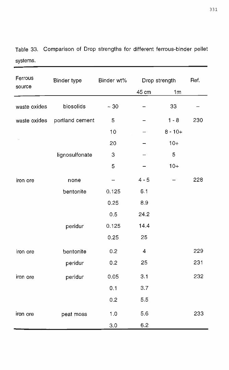
331
Table 33. Comparison of Drop strengths for different ferrous-binder pellet
systems.
Ferrous
source
waste oxides
waste oxides
iron ore
iron ore
iron ore
iron ore
Binder type
biosolids
Portland cement
lignosulfonate
none
bentonite
peridur
bentonite
peridur
peridur
peat moss
Binder w t %
- 3 0
5
10
20
3
5
—
0.125
0.25
0.5
0.125
0.25
0.2
0.2
0.05
0.1
0.2
1.0
3.0
Drop strength
45 cm 1m
—
—
—
—
-
—
4-5
6.1
8.9
24.2
14.4
25
4
25
3.1
3.7
5.5
5.6
6.2
33
1 -8
8-10+
10+
5
10+
—
Ref.
—
230
228
229
231
232
233

332
Table 34. Comparison of dry compressive strength for different ferrous-binder
pellet systems.
Ferrous Binder type Binder wt% ComPressive induration Ref. source strength (N)
waste oxides biosolids 30 156 nil
waste oxides
waste oxides
bentonite
Portland cement
lignosulfonate
2
5
10
20
3
5
950N
4125
11060
17375
8250
24000
1250°C
cold cure
223
230
waste oxides portland cement 4 25- 132 120°C 234
waste oxides
iron ore
iron ore
iron ore
iron ore
iron ore
-
Portland cement
molasses +
Portland cement
dolomite bentonite limestone peat moss
peat moss
none
bentonite
peridur
peridur
3
7 + 7
upto 1 upto 1 upto 19 upto 3
1.0
3.0
1.0
3.0
0.25
0.25
0.05
0.1
0.2
445-;
1300
2060-
34
33
2354
2217
1.7
6.0
8.5
3286
2649
4787
2230
•2750
—
105°C
(10days)
1300°C
105°C
1310°C
nil
1340°C
62
75
235
233
228
232

333
pellets were found to be very resilient to brittle failure during compression
testing. Rarely did the samples fail catastrophically, generally after reaching
the peak compressive load the samples plastically deformed. The behaviour
of other pelletised systems under compressive loads is not commented upon
in the studies referenced in Table 34, however it is clear that sewage sludge is
a non-rigid binder.
Abrasion and heat shock resistance were not quantitatively evaluated by a
standardised test method, however, a qualitatively idea of the resistances can
be gauged from observations m a d e during pilot plant and laboratory scale
smelting trials. Abrasion of the composite pellets was observed in the 100kg
D C arc furnace feed system, vibratory unit, to be approximately 5 % of the total
feed. The thermal shock resistance of the composite pellets is extremely high
given the observation that pellets did not spall or catastrophically fail on being
charged onto a slag at 1500°C.
The composite pellets were determined to have an apparent porosity of 5 2 %
with a bulk density of 1.38 g/cm3. It is difficult to compare the density of the
composite pellets to other systems because of the influence of the raw
material components on density, however, it is apparent that the porosity is
much higher than other pelletised ferrous systems. Typically iron ore pellets
have porosities of 20-30% with a few reported values approaching 4 0 %
[231,233,235].
Particle size analysis of the composite pellets determined the average size
was in the range of 10 to 15 urn, as can be seen in Figure 136 the overall
distribution varied from submicron to in excess of 100p.m. Table 35 lists the
size analysis of the individual components that constitute the composite
pellets, the data explaining the bi-modal nature of the distribution. The finer
components in the composite pellets are clearly carbon black (supplementary

334
Vol %
0.01 1000
Particle size (u.m)
Figure 136. Particle size distribution of composite pellet as used in the
EnvlRONment process.

335
Table 35. Particle size for raw material components of the EnvlRONment
process composite pellets.
Material Mean particle size (u.m) 90% particles less than Qnm)
sand 300 575
lime 82 450
carbon black 0.4 1.5
I.B.D 1.4 14
sewage sludge 106 770
Note; I.B.D - Iron Bearing Dust, mixed BF and BOS filter cake material.

336
carbon) and the ferrous waste material (Iron Bearing Dust). The coarser
components are fluxing agents (lime and silica) and sewage sludge. A typical
X R D pattern for a composite waste pellet is illustrated in Figure 137.
Interpretation of the mineralogy of the composite from the X R D pattern is
difficult, the use of pure standards and raw materials did not provide much
more information mainly because the waste ferrous material (I.B.D) is a multi-
component material. The difficulty in determinging the mineralogy of iron and
steelmaking wastes using X R D , particularly for minor components such as
zinc, has been previously recognised [35,50,52], it would appear that the
composite pellets because of a dilution effect are a little more difficult
characterise.
The majority of peaks measured in the composite pellets were identified as
originating from the waste ferrous material (I.B.D), individual species identified
were limited to C a C 0 3 , Fe20 3, Fe°, and Si02. This agrees with similar studies
performed on iron and steelmaking wastes as described in section 2.3
[22,35,36,50,52].
Typical microstructures observed in the composite pellets are shown by
brightfield optical images in Figures 138 to 141 and darkfield images in
Figures 142 and 143. The images show numerous particles of varying size
and morphology. Although microstructurally and mineralogically complex
many individual particles were clearly indentified. S E M - E D S indicated most
of the larger particles were flux additions and carbon black, while the large
fibrous particles visible in Figures 138 to 140 were reasoned to be exfoliated
coke particles originating from the I.B.D material. The bright spherical
particles, abundant in many of the composite pellets, were identified as
metallic iron and were often surrounded by an outer layer of oxide. The larger
iron particles exhibited a variation in microhardness values of 100 to 1000 Hv,
indicating a variable carbon content. Figures 144, 145 and 146 depict

337
individual particles linked with their typical particle size, microhardness and
E D S spectrums, the figures showing a silica particle, an exfoliated coke
particle, and metallic iron particles respectively. Smaller sub-micron particles
were observed in the binding matrix of the pellets, however much of the
material could not be resolved optically, this included the biosolids fraction.
Although the sewage sludge is soft it is relatively tough due to its fibrous
nature, it is most likely that the sample preparation method was too severe, in
particular the final polishing stages, destroying the fibres. A better method to
study the fibres in the sewage sludge m a y have been to examine fracture
surfaces.
Optical microscopy also revealed that the porosity of the composite pellets
was not uniform, the tortuosity and pore structure varying considerably
throughout the pellets.
7.4 Conclusions.
Characterisation of the composite pellets as used in the EnvlRONment
process investigated strength, microstructural and mineralogical aspects.
The composite pellets were found to have a drop strength of 33 D F M which is
greater than published data for other pelletised ferous systems. Compressive
strength was measured to be 156N, the pellets deforming plastically rather
than failing catastrophically via brittle fracture mechanisms.
The superior strength properties of the composite pellets is reasoned to be
due to the excellent binding properties of the biosolids component. The
sewage sludge together with the high porosity imparting reasonable abrasion
resistance and sufficient heat resistance to allow the composite pellets to be
fed into a smelting furnace at 1500°C without failing.

20 30 40 50 60 70 80 90
Degrees 2-Theta
Figure 137. XRD pattern of EnvlRONment process composite pellet.
perfomed using Cu radiation and a Ni filter.

339
Figure 138. Typical microstructure of composite EnvlRONment pellet.
Figure 139. Typical microstructure of composite EnvlRONment pellet.

340
Figure 140. Typical microstructure of composite EnvlRONment pellet.
Figure 141. Typical microstructure of composite EnvlRONment pellet.

341
Figure 142. Typical microstructure of composite EnvlRONment pellet.
Figure 143. Typical microstructure of composite EnvlRONment pellet.

342
Particle size 5-250 u.m
Microhardness 720-1150 H v
Figure 144. Silica particle identified in composite EnvlRONment pellet.

343
Particle size 20-800 jam
Microhardness < 1 O H v
^ t ^ ^ ^
Figure 145. Exfoliated carbon particle identified in composite EnvlRONment
pellet.

344
Particle size <1-150 pin
Microhardness 100-1000 H v
Figure 146. Metallic iron particles particle identified in composite
EnvlRONment pellet.

345
Microscopical evaluation showed that the microstructure and mineralogy of
the pellets was complex and diverse, exhibiting localised non-homogeneity,
which was corroborated by further physical and chemical characterisation.
The results of the characterisation were not unexpected given the nature of
the waste components being processed, however the study indicated that the
pellets from the EnvlRONment process would be impractical to use in
controlled laboratory studies of kinetics and reaction mechanisms, as
complexity would make microstructural/mineralogical interpretation ardous.

346
Chapter 8 Experimental
8.1 Introduction.
The smelting of steelworks dust and organic waste, as performed in the
EnvlRONment process, w a s investigated. Smelting, X-ray, and
thermogravimetric experiments provided foundation for an in-depth study of
reaction kinetics and mechanisms, while also allowing other relevant issues of
waste processing, using bath smelting technology, to be addressed.
Characterisation of actual process pellets as used in pilot plant trials, see
section 7.3, revealed microstructural complexity and localised
nonhomogeniety. A conclusion of the characterisation and preliminary
laboratory smelting experiments, was that process pellets were not suited for
the intended study. To allow for accurate experimental interpretation, and to
increase the degree of experimental control, process pellets were replicated
by surrogate laboratory pellets with a simplified number of components.
Selection of components in the surrogate composite pellets was based on
several assumptions regarding typical raw materials consumed in the
EnvlRONment process. It was assumed that steelworks dust was suitably
replicated by a mixture of Fe20 3, graphitic carbon, and the fluxes CaO, Si02,
and MgO. The artificial steelworks dust thus being absent of agents, such as
S and metallic Fe, which have a known effect on carbothermic reduction of
iron oxide. Notably no zinc phases were selected for inclusion, although
considered one of the major issues in processing iron and steelmaking
wastes zinc components appear to have minimal influence on smelting,
particularly at the levels in the process pellets, see Table 19.
Far greater difficulty was encountered in determining a replicant for the
organic waste component. The most commonly used waste in the pilot plant

trials was sewage sludge, however its use in controlled laboratory
experiments is undesirable. Sewage sludge contains pathogens, has a
stigma attached to it due to its origins, and exhibits considerable chemical
variability [236,237]. It is also unknown whether the behaviour of sewage
sludge would be indicative of a broader spectrum of organic wastes that the
EnvlRONment process was conceptualised to treat. Although finding a single
material to replicate the carbothermic behaviour of sewage sludge is
sufficiently involved to warrant an in-depth investigation of its own [238-242], it
was decided that cellulose be trialled as the organic waste component [243].
A brief report in Appendix D elaborates salient points of the selection process.
Cellulose was selected on the basis that it: has similar ratios of C, H, and O to
sewage sludge; is the major component of sewage sludge; is a waste product
in several industries; is a volatile carbonaceous material; is fibrous.
8.2 Smelting Experiments.
8.2.1 Apparatus.
The apparatus used for the smelting experiments is shown schematically in
Figure 147. Smelting experiments were performed using an induction furnace
for heating (Heraeus, 10Hz - 25kW). To overcome the problem of inductively
heating the required volumes of slag clay-graphite crucibles were used as
susceptors to increase the heating load. To minimise slag erosion of the
crucible, and the subsequent ingress of graphite, into the melt a zirconia
(Zr02) wash was applied to the crucibles and dried prior to use.
Although the field of thermometry has been extensively researched,
measurement in hot environments such as slag, for extended periods, still
remains difficult, for this reason a non intrusive technique was chosen.
Smelting by nature can generate considerable offgas and fume, these are

348
I Fuma ce induction
coils
Sheathed R -type thermocouple
Compensating extension wires
Figure 147. Schematic diagram of experimental apparatus used for smelting
experiments.

349
likely, together with background radiation such as generated by the graphite
crucible, to interfere with the measurements made by an optical pyrometer.
Apart from a clear field of view, a pyrometer also requires an emissivity
calibration for the material which is being measured, unless a more expensive
dual wavelength pyrometer is used. For these reasons the thermocouple
route was preferred over pyrometry.
A Pt/Pt - 13%Rh, ungrounded junction, thermocouple (R - type) was used to
measure temperature. The thermocouple, sheathed in alumina, was
positioned below the reaction crucible in which a small well was drilled to aid
thermal contact. This configuration, with the thermocouple outside of the
immediate vicinity of the induction coils, resulted in negligible E M interference.
Compensating cable was used to connect the thermocouple wires to a digital
meter (Eurotherm 818P). The thermocouple wires being a sufficient length to
ensure the temperature of the thermocouple and compensating wires junction
was less than 200°C.
A correction was made to the meter reading to account for temperature
difference between the slag and the bottom of the reaction crucible, where the
thermocouple tip was located. A difference of 250°C, at a slag temperature of
1500°C, was interpolated from calibration of the slag-crucible-thermocouple
system. The calibration is described in Appendix E.
8.2.2 Materials.
Commercial, high purity, materials were used in the smelting experiments,
materials used to make surrogate EnvlRONment feed are listed in Table 36.
Where possible materials were obtained with particle sizes similar to those
determined during waste characterisation, see section 7.3. Further sizing was

350
Table 36. R a w materials for smelting experiments.
Material
Fe203
Graphite
Cellulose
Si02
M g O
CaO
Particle size
-5|i
+1-2|i
t
§
§
§
Purity (%)
99+
not < 98
97.5
not < 98
not < 96
not < 98
Brand
Aldrich
Aldrich
Sigma
Ajax
Ajax
Ajax
t Sized by dry sieving to -53u.m +38um microns.
§ Sized by dry sieving to -38u.m.

351
achieved by dry sieving, this eliminated agglomerates and provided
experimental control.
Cellulose, which was used to replicate organic waste, was obtained in
medium fibrous form (fibers of 50-350u.m length), while graphite was used as
the carbon source; in pilot plant trials carbon black was used as
supplementary carbon, see section 4.4.1.
Materials for the synthetic slag required for the smelting experiments were
commercially obtained, the purity of the raw fluxes are listed in Table 37.
8.2.3 Experimental Procedure.
Sized raw materials were weighed and then mixed by tumbling on a rolling
machine for 2 hours. Preliminary work had determined 2 hours to be long
enough to ensure a homogenous mix, without destroying the fibrous nature of
the cellulose. A desired amount of the mixed material, as shown in Table 38,
was then weighed and poured into a cylindrical die, uniform filling was
achieved by tapping the die several times. Dry uniaxial pressing was then
used to agglomerate the material into small cylindrical discs, referred to as
pellets. Agglomeration was carried out without lubricants and binders, at a
typical pressure of 250MPa. The density of the pellets was then determined
by direct measurement, as outlined in Australian Standard A.S 1774.5 1989
[226].
Smelting of the pellets was performed in a synthetic slag, the CaO-MgO-Si02
slag was chosen to meet requirements of the EnvlRONment process, low
melting point, basicity of at least 1.5, and a M g O content of approximately 12-
15%. Synthetic slag property values are listed in Table 39.

Table 37. Purity of Materials for Synthetic Slag.
Material Purity (%)
Si02 99
MgO 97
CaO 96

Table 38. Nominal Sample Weights.
Die diameter (mm)
10
15
20
25
30
Nominal Pellet Weight (g)
0.9
3.0
7.1
13.9
24.0

354
Table 39. Synthetic Slag Properties.
Property Value
CaO 3 9 %
M g O 19%
SiO£ 42%
Melting Point 1440°C
Density (1500°C) 2.65g/cm31
Viscosity 0.23Ns/m2 §
§ Viscosity calculated using model attributed to Urbain et al cited in Mills and
Keene [244].
t Density estimated using molar volume additive method [244].

355
500g of synthetic slag was melted in the reaction crucible using the induction
furnace arrangement as shown in Figure 147, after melting the slag
temperature was raised to 1500°C. The CaO-MgO-Si0 2 equilibrium phase
diagram is shown in Appendix F.
Individual pellets were dropped from a height of 20cm onto the molten slag; by
using an open top crucible arrangement it was possible to observe smelting.
Apart from measuring smelting time, reaction progress was also followed by
retrieving pellets from the slag during the course of smelting. Pellets were
removed from the slag by dipping them out with a cradle, then quenched in
water to halt further reaction.
Partially smelted samples were measured to determine weight loss and size
reduction. Sectioning, mounting and polishing, as described in Appendix C,
produced samples for metallography.
Standard techniques were used to characterise the partially smelted pellets
using electron and optical microscopy. Optical microscopy was aided by use
of etchants which selectively highlighted certain phases within the specimens,
as outlined in Appendix G. Partially smelted pellets were also characterised
using xray diffraction, as outlined in Appendix H.
Experimental control was maintained by using new clean synthetic slag for
each trial. Variability between, and within, trials due to differences in slag
chemistry and temperature were accounted for by measuring the smelting
time of a standardised pellet at the start and end of each trial.
A matrix of sample types was drawn based on 3 parameters relevant to
smelting operations in the EnvlRONment process; pellet chemistry, pellet size,
and pellet density. In general, 1 parameter was varied while the other 2 were
held as controls.

356
Five different chemistries were chosen for investigation, the focus of each type
being; volatile carbon content; Fe203:C ratio; flux content; and the use of iron
as a catalyst. All pellets were 1 5 m m in diameter.
Type 1 pellets contained only cellulose and hematite, Table 40 lists the
compositions trialled.
The effect of varying hematite to carbon ratios was investigated with Type 2
pellets. Table 41 shows the ranges of ratios trialled, cellulose was held
constant at 2 0 % to approximate realistic operating practise.
The effect of flux content on smelting was investigated using pellet chemistries
with 2 different flux levels. Table 42 shows the chemistries trialled. Pellet type
3.1 has flux contents typical of steelworks dust, while type 3.2 has higher
levels as per supplementary additions practised in the EnvlRONment process,
see section 4.2. In both chemistries a stoichiometric Fe203:C (1:3) ratio was
used. Because type 3.2 pellets most closely match actual process pellets this
chemistry was selected as the "standard" for investigating the effect of pellet
size and density. To isolate and identify any possible effect that particulate
iron may have as a catalytic agent on pellet smelting, a simple pellet chemistry
was chosen. The Fe20 3:C ratio was 1:3, while catalyst levels were between
0.5 and 2 0 % , as shown in Table 43.
The effect of pellet size on smelting was investigated using pellets with
constant chemistry, (type 3.2 - see Table 42). The size of the pellets trialled is
shown in Table 44.
The effect of pellet density was investigated using 1 5 m m diameter size pellets
with the type 3.2 chemistry, see Table 42. Control over pellet density was
achieved by using different compaction pressures during the agglomeration
stage, typical densities varied with chemistry, but were in the range of 1.6 to
2.6g/cm3.

Table 40. Type 1 Samples.
Pellet Type Cellulose (%) Hematite (%)
1.1 20 80
1.2 40 60
1.3 60 40
1.4 80 20

Table 41. Type 2 Samples.
Pellet Type Fe203:C Ratio Cellulose (%)
2.1 1:1.5 20
2.2 1:3 20
2.3 1:4.5 20
2.4 1:6 20

359
Table 42. Type 3 Samples.
Pellet Type Fe203 C Cellulose CaO MgO Si02
3.1 54.8 12.4 20 7.2 3.2 2.4
3.2 47.7 10.8 20 9.7 2.8 9.05

360
Table 43. Type 4 Samples.
Pellet type
4.1
4.2
4.3
4.4
4.5
4.6
Fe203
64.87
64.46
63.65
61.2
57.12
48.96
C
14.63
14.54
14.35
13.8
12.88
12.04
Cellulose
20
20
20
20
20
20
Iron
0.5
1.0
2.0
5.0
10
20

361
Table 44. Sample Sizes.
Pellet Diameter (mm) Pellet Height (mm)
10 4-6
15 6-9
20 10-12
25 12-15
30 17-18

362
8.3 Xrav Fluoroscopy and Radiography Experiments.
A series of smelting experiments were undertaken using Xray fluoroscopy and
radiography techniques to observe the progress of reaction. The experiments
were performed at the Centre for Iron and Steel Research (CISR) within the
Department of Metallurgical Engineering and Materials Science, Carnegie
Mellon University, Pittsburgh, USA.
8.3.1 Apparatus.
The apparatus used for the smelting Xray fluoroscopy/radiography
experiments is shown in Figure 148 and schematically in Figure 149. The
main components of the apparatus are the furnace, xray generator, and the
xray receiving systems.
Heating was provided by a custom built, SiC, electric resistance vertical tube
furnace. Temperature was measured, in the uniform hot zone, using a
sheathed R-type thermocouple. Temperature control was achieved through a
furnace controller (Omega) which linked the thermocouple and furnace in a
control loop. A further feature of the furnace was 2 ports (120mm diameter) in
the side walls. The ports allowed Xrays relatively undisturbed propagation
before and after the reaction tube.
A commercial Xray generator (Raymax 2100 - Medical) was used to provide
Xrays for fluoroscopy and radiography experiments, the generator being
positioned to maximise the path of xrays through the side ports in the furnace.
Images from transmitted Xrays were generated by exposing plate film to
produce still images, radiography, or using the image intensifier to produce
real time images, fluoroscopy. A video camera connected to the image
intensifier enabled images to be simultaneously viewed and recorded using a
TV-VCR.

363
Figure 148. Photograph of Xray unit and furnace.
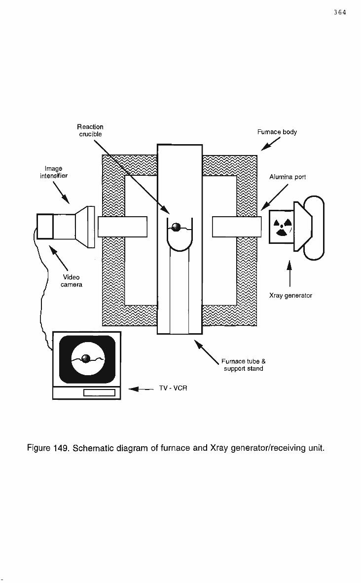
364
Reaction crucible
Image intensifier
Xray generator
Furnace tube & support stand
TV - VCR
Figure 149. Schematic diagram of furnace and Xray generator/receiving unit.

365
8.3.2 Materials.
Materials used to make surrogate EnvlRONment pellets are the same as those
described in section 8.2.2. Materials for synthetic slag were commercially
obtained, the purity of raw fluxes is listed in Table 45.
8.3.3 Experimental Procedure.
Surrogate EnvlRONment pellets were prepared as described in section 8.2.3.
Xray smelting experiments were performed in a synthetic slag, the AI203-CaO-
Si02 slag was selected on the basis of previous research [213] which found
this composition to be suitable for xray studies, providing a low melting point
and good material contrast. Synthetic slag property values are listed in Table
46.
An alumina reaction crucible (55mm diameter) was used to hold 300g of
synthetic slag, the crucible placed in the uniform hot zone within the furnace
reaction tube. After melting and heating the slag to 1450°C the crucible was
positioned to ensure the top surface of the molten slag was in the field of view
of the xrays.
Surrogate pellets were individually added to the molten slag by hand
dropping them from above, falling approximately 55cm to the slag surface,
after dropping the pellets the xray generator was turned on. In fluoroscopy
mode the Xray generator was run continuously until smelting had completed,
providing real time images on the TV monitor, while in radiography mode still
images were taken at given time intervals during smelting.
A matrix of sample types, similar to those described in section 8.2.3, was
drawn based on 2 parameters, pellet chemistry and pellet size. Sample
designation are the same as those used in section 8.2.3. The reduced

366
Table 45. Purity of Materials for Synthetic Slag.
Material Purity (%)
Al203 not < 98
CaO not < 98
Si05 not < 98

367
Table 46. Synthetic Slag Properties.
Property
Al203
CaO
Si02
Melting Point
Density
Viscosity
Value
10%
49.1%
40.9%
~ 1320°C
2.73g/cm3 t
0.57Ns/m2 §
§ Viscosity calculated using model attributed to Urbain et al cited in Mills and
Keene [244].
t Density estimated using molar volume additive method [244].

368
number of variables was chosen as during planning it was unknown as to the
effectiveness of the Xray techniques for investigating smelting of
EnvlRONment type pellets.
3 different chemistries were investigated, these focused on the effect of
volatile carbon content, the Fe203:C ratio, and the effect of fluxes. All pellets
were 1 5 m m in diameter. Table 47 lists the chemistries trialled.
The effect of pellet size on smelting was investigated using pellets of type 3.2,
see Table 47, the size of pellets trialled is shown in Table 48.
New reaction crucibles and synthetic slag were used for each trial. Pellet
smelting was investigated by examination of the resulting video tape images
from fluoroscopy, film images from radiography, and physical products of the
trials: reaction crucibles; slag; and reduction products.
8.4 Thermogravimetric Experiments.
Thermogravimetric techniques were used to investigate kinetics and
mechanisms of reduction of composite iron oxide carbon pellets. Thermal
analysis via this route was selected because the experimental techniques are
well understood and it is the most suited means to investigate temperature
dependant phenomena.
8.4.1 Apparatus.
The apparatus used for the thermogravimetric experiments is shown
schematically in Figure 150. The main components of the apparatus are the
tube furnace, gas control system, analytical balance, data logging and furnace
control system.

369
Table 47. Xray Smelting Samples.
Pellet Type Cellulose (%) Fe203 (%)
1.1 20 80
1.2 40 60
1.3 60 40
Pellet Type Cellulose (%) Fe203:C
2.1 20 1:1.5
2.2 20 1:3
2.3 20 1:4.5
Pellet Type Fe203 (%) C (%) Cellulose (%) CaO (%) MgO (%) Si02 (%)
3.2 47.7 10.8 20 9.7 2.8 9.05

Table 48. Sample Sizes.
Pellet Diameter (mm)
15
20
Pellet Height (mm)
6-9
10- 12
30 17 -18

371
Balance
Gas vent to fume cupboard
2 zone tube furnace
••••••••DD •••••••••• DDDDDDDDDD
Cu turnings furnace
R-Type thermocouples
Figure 150. Schematic diagram of apparatus for thermogravimetric
experiments.

372
Heating was achieved in a 80cm vertical tube furnace, the 2 zone SiC
resistance furnace being installed with a 7 0 m m diameter alumina reaction
tube.
The thermogravimetric unit was constructed to operate with a controlled
atmosphere, gas was sourced from bottles through a special low flow
regulator (BOC-Comet), the low flow regulator maintaining constant pressure
at low flows. The nitrogen gas line was constructed with an oxygen removal
furnace in line, nitrogen prior to a variable flow meter (Fischer and Porter, 1/8")
passing through a small tube furnace packed with Cu turnings heated to
600°C to remove oxygen. The flowmeter was installed with the control needle
valve on the outlet so as to maintain constant line pressure while controlling
gas flow. After the flowmeter, maximum flowrate of 2.57l/min, the gas was
passed through a series of flashback arrestors and non return valves and then
into a vertical column packed with silica gel beads to remove any residual
moisture in the gas stream. Gas was admitted into the bottom of the tube
furnace via a leak proof aluminium cap, after passing up through the tube
furnace, and reacting with the sample, the gas was vented through an outlet of
the upper cap via tubing (20mm diameter) to a fume cupboard.
Sample weight was measured using an analytical balance positioned above
the furnace tube (Sartorius A200S, 4 decimal place). A wire (Nichrome) and
crucible (recrystallised alumina) arrangement was used to suspend samples
from the bottom pan of the balance into the furnace. The suspension wire
passing through the top furnace cap through a hole only slightly larger than
the wire diameter (0.7mm). The crucible, shown in Figure 151, was open top
and with a low side wall, ensuring that there was little restriction to gas flow to
and from the sample.

373
Figure 151. Recrystallised alumina crucible as used in thermogravimetric
experiments.

374
Temperature within the furnace was measured via 2 sheathed (4mm O.D)
Pt/Pt-13%Rh (R-type) thermocouples, 2 thermocouples were required due to
the furnace having 2 heating zones. For ease of operation the thermocouples
were designed to enter the furnace via the bottom cap, their relative positions
being adjustable via locking sleeve mechanisms. Thermocouples were
positioned on opposite sides of the reaction tube in close proximity to the wall.
Compensating cable was used to connect the thermocouples to R-type signal
amplifiers (Analog Devices, 5B-47) in the furnace control box. Thermocouple
wires were sufficiently long to ensure that the temperature of the
thermocouple and compensating wires junction was less than 200°C,
furthermore the signal amplifiers were cold junction compensated.
Signals from the R-type thermocouple input to amplifier modules which
amplify the signal providing an output voltage between 0 and +5V, the
amplifiers produce a linear signal between 500 and 1750°C, i.e. 0V = 500°C
and 5V = 1750°C. The amplifiers output signal is then inputted to the
computer which in return drives high voltage switching devices (triacs),
located in the furnace control box, to provide control of the furnace heating
elements. Because the signal amplifiers did not produce a linear signal below
500°C it was necessary to write a look-up table for temperature measurement
and control below 500°C. Calibration for the look-up table was done on line,
in 1°C steps, to provide accurate temperature readings, and was written into
the control software in the form; output voltage = temperature, as indicated by
the look-up table.
A PC running Labview Software (version 3.01) was used to provide furnace
control and data logging, Figure 152 shows a block diagram of the control
loop used. The modular nature of the software allowed a simple one page
control screen to be constructed.

375
Balance
PC Labview
Furnace Furnace Controller
Figure 152. Block diagram of thermogravimetric control loop.

376
The control screen menu allowed for operator control of heating schedules,
PID values, data logging, and weight correction factors. Available display
information includes; furnace zone temperatures, set point temperatures, trial
running times, heating element power, relative weight change, and absolute
weight. Data logged by the Labview software was tab deliminated, and in the
form;
time, temp-1, temp-2, weight;
where time is the computer time, temp-1 is the upper zone temperature, temp-
2 is the lower zone temperature, and weight is the absolute weight read by the
balance with weight correction applied.
To minimise any potential system influence on the thermal analysis data, in
particular spurious weight changes, particular care was taken with apparatus
design and construction. Equipment commissioning involving considerable
calibration, utilising empty crucible and inert sample tests for system
assessments.
The balance was placed on a solid horizontal platform to minimise vibration
effects, while an aluminium reflector plate and fibre insulation protected the
balance from any direct radiation and convection heating during furnace
operation. Hot testing of the balance arrangement verified that these
measures were sufficient to stop balance mass drift up to a furnace
temperature of 1200°C.
Thermocouple location within the reaction tube was adjusted to provide a
uniform hot zone, the optimum positions being where the zone was large
enough to accommodate the entire crucible/sample arrangement and where
the zone temperature matched the thermocouple readings. The temperature
profile of the furnace at 1200°C is shown in Appendix I.

377
Preliminary work also showed that, at the expected heating and gas flow
rates, the system mass-temperature dependency was less than the limit of
reading of the balance, similarly no buoyancy effects were detected from gas
flow variations. Calibration indicated that at furnace temperatures of 500 to
1200°C the true temperature within the uniform hot zone was ±10°C and a
balance mass discrepancy of ±0.0002g.
8.4.2 Materials.
Materials used to make surrogate EnvlRONment pellets for the
thermogravimetric experiments are the same as those described in section
8.2.2. Nitrogen gas was commercially obtained, the gas purity is listed in
Table 49. Oxygen in the nitrogen was further reduced to p 0 2 = 10"14 by
passing the gas through the Cu turnings furnace at 600°C, as calculated from
an Ellingham diagram.
8.4.3 Experimental Procedure.
Surrogate EnvlRONment pellets were prepared as described in section 8.2.3.
To avoid any mechanical degradation pellets were prepared immediately
prior to testing, preliminary work had indicated possible loss of handling
strength over time [245].
Thermogravimetric experiments were performed with a controlled non-
interactive atmosphere, nitrogen was chosen because it was the most suited
gas for standardising experimental conditions while having minimal direct
effect in any sample reaction.

Table 49. Gas Purity.
Material
Nitrogen
Moisture
Oxygen
Composition
99.99%
< 12 ppm
<10 ppm

379
A single sample was used per trial, the sample being pre weighed on the
thermo balance. The weights of the balance pan hook, suspension wire and
sample crucible were also measured before the start of each trial, the total of
these 3 being the correction weight. Prior to use the balance was calibrated
and then checked against a certified weight to monitor trial to trial variation,
which was measured to be less than 0.0005% of the reading.
The sample was placed in the crucible, as shown in Figure 153, and then
lowered into position in the furnace, fine adjustments ensuring that the
crucible was not touching the furnace tube walls and that the suspension wire
movement was free of obstructions. Once the sample/crucible arrangement
was in place the entire system was left for 30 minutes to settle and equilibrate.
Nitrogen was flowed at a rate of 2.5l/min, trials not being started until the gas
flow was constant. Preliminary experiments had found that sample reaction
became independent of gas flow above 2.3l/min, the variation in sample
reaction with gas flow is shown in Appendix J.
At the end of each trial, the sample/crucible arrangement was immediately
raised out of the hot zone and allowed to cool in flowing nitrogen. Samples
were weighed again, as was the balance pan hook, suspension wire, and
crucible, to check that weight loss had been solely due to sample reaction.
Samples were characterised using xray diffraction, metallography, and
microscopy as outlined in Appendix G and H. A limited number of samples
were also chemically analysed, the speciation of iron and its oxides being
determined at Central Laboratories, BHP, Port Kembla, Appendix K briefly
outlines the analytical techniques used.
The matrix of sample types chosen was the same as those described in
section 8.2.3, however only effects of pellet chemistry were investigated. It

380
Nichrome wire
Alumina crucible
I ron oxide-carbon sample
Figure 153. Schematic diagram of sample in crucible for thermogravimetric
experiments.

381
was felt that the effects of pellet size and density were better studied in the
smelting in slag experiments. Tables 40, 41, 42, and 43 list the compositions
of the pellets trialled, all pellets were 1 5 m m in diameter. The 1 5 m m diameter
size pellets were selected as these provided a good balance between
achieving temperature uniformity, as size decreases temperature becomes
uniform, and sample homogeneity. A pellet smaller than 1 5 m m is also shifting
away from reasonable feed sizes expected to be used in commercial
operation of the EnvlRONment process.
Thermal analysis was performed non-isothermally up to temperatures of
1200°C, linear heating ramp rates of 2 and 5°C/min being used. Heating
rates were selected based on several experimental and equipment
considerations. The furnace was not capable of maintaining linear heating
rates to 1200°C much faster than 5°C/min, while temperature distributions
within a sample are more uniform with slow heating rates, such as 2 and
5°C/min. To obtain samples for metallographic examination some trials were
halted before 1200°C. Apart from the samples, data was available from
analysing the weight and temperature measurements recorded during the
trials.

382
Chapter 9 Results
9.1 Smelting Experiments.
9.1.1 Introduction.
Smelting of composite pellets as performed in the EnvlRONment process was
simulated in the laboratory by smelting surrogate composite pellets in
crucibles as described in section 8.2.
Although considerable time was spent on developing the experimental
apparatus for the smelting experiments, overall the experimental scope was
limited because difficulties encountered could not be satisfactorily overcome
given equipment availability.
It is doubtful that the crucible tests truly reflected pilot plant smelting because
there was no controlled reducing atmosphere above the crucible bath.
Temperature gradients in the slag layer were steep, it being particularly
difficult to minimise heat losses because of the need to visually observe
smelting reactions. The cooling effect of the open space above the crucible
being evident by the observed freezing of slag on the exposed pellet surface
during smelting. Because of the heat losses it was difficult to maintain melt
fluidity for large volumes of slag. Several attempts to solve the heat loss/low
slag fluidity problem were all relatively unsuccessful. Increasing the heating
power from the induction furnace resulted in an unrealistically turbulent slag,
which quickly eroded through the zirconia wash and reaction crucible, similar
failures occurred using slag fluidisers such as CaF2. Attempts at increasing
the heat load into the slag layer by using an iron heel in the crucible worked,
however the turbulence of the slag was increased dramatically as was the
subsequent crucible erosion. Erosion of the crucible was not so much a
problem in that available test times were short, due to breakout of the melt, but
the effect of erosion on the actual melt itself. Erosion of the clay-graphite

383
crucible resulted in the slag chemistry shifting because of the dissolution of
clay components, the melting point becoming variable and unknown.
Graphite from the crucible was seen to float to the slag layer surface, this
presents problems in interpreting smelting-reduction reactions because of the
unknown quantity of graphite in vicinity of the composite pellets, which
feasibly could react directly with the pellet during smelting.
Founded on the premise that the smelting-reduction of composite pellets is
heat transfer dependant, and given the difficulties of indirectly heating slag
using an induction furnace, attempts were also m a d e at performing smelting
experiments using iron as the melt rather than slag. This also proved to be
unsuccessful because of the nature of induction heating. The resulting
convex surface of the iron melt meant that pellets added to the crucible rolled
to an edge, as shown schematically in Figure 154, where they reacted
partially against the crucible wall, partially on the iron, and with time an
increasing slag layer; the slag layer forming as a result of crucible erosion and
from the flux components in the composite pellets. Experiments using the iron
heel had poor reproducibility because of the mixed and changing reaction
medium.
Apart from the difficulties with the heat losses and the subsequent poor control
over slag temperatures, retrieving pellets during smelting w a s not
straightforward. Sample quenching to halt reaction progress often destroyed
the integrity of the samples, while removing the samples from the slag layer
also removed considerable amounts of slag making it difficult to discern the
reaction front of the pellet.
Notwithstanding the difficulties and shortcomings of the experimental
apparatus, which essentially m a k e it impossible to accurately quantify
smelting-reduction reactions, the experiments still provided significant

Clay-graphite crucible wall
slag pool buildup
Z r 0 2 wash
composite pellet
iron bath
Figure 154. Schematic diagram of smelting with an iron bath using induction
heating.

385
fundamental information relevant to an understanding of smelting reactions in
the EnvlRONment process.
9.1.2 Smelting Experiment Results.
The smelting behaviour of composite pellets, surrogate and process, were
observed during pilot plant and laboratory trials. Pellets fed to the slag layer
generate sufficient m o m e n t u m during the falling region that the pellets
penetrate the slag phase, the m o m e n t u m being quickly lost with the pellet
immediately floating to the surface. All pellets regardless of density were
found to float on the slag layer. During the short immersion period it was
observed that pellets were not wetted by the slag, off gas evolution from the
pellet also being sufficient to maintain an open entry path in the slag.
Increasing charge momentum, achieved by increasing the fall height, did not
overly appear to increase penetration depth, neither did pellet density within
the range trialled.
In general, the composite pellets did not catastrophically fail due to heat shock
on being charged to the slag layer. Process pellets produced using extrusion
were not observed to fail, while those produced by briquetting tended to fail
along the centre consolidation line. Pellets prepared in the laboratory using
dry uniaxial pressing frequently suffered spalling on the top and bottom
surfaces, this w a s observed for pellets produced from process materials and
the simplified surrogate materials. Within the range of chemistries trialled the
heat shock resistance of the pellets was similar, increasing the volatile carbon
(cellulose) content from 20 to 8 0 % appeared to have little effect, neither did
the addition of flux agents.

386
Observation of the initial charging sequence also revealed that no immersion
crust layer formed on the pellets. During some crucible trials it was observed
that small islands of frozen slag had formed underneath the pellets once they
floated to the slag surface. This phenomena was not observed in the pilot
plant trials, but could have been easily overlooked because of restricted
viewing access. Removal of the pellets during smelting indicated no
significant ingress of slag into the pore structure during the majority of
smelting.
During smelting the composite pellets were in constant motion, the tumbling
motion resulting in a generally uniform dissolution pattern, pellet motion being
driven by the off gas evolved within the pellet during smelting. The extent of
pellet motion was influenced by the volatile carbon content, pore structure and
moisture content. In one series of tests several pellets were immersed in
water and only partially dried prior to smelting, these reacted considerably
more vigorous than the fully dried pellets.
A more vigorous reaction was also achieved by forcibly submerging the
composite pellets into the melt. Fully submerging the pellets into the slag
layer resulted in vigorous activity, as indicated by the sudden increase in slag
agitation. For the trials were an iron heel was used underneath the slag layer
submerging the pellets into the iron heel resulted in violent reactions, causing
ejection of slag and iron into the free space above the melt.
From those trials where small islands of slag froze underneath the pellet
during smelting streams of molten material could be observed flowing from the
pellet. As the material flowed from the pellet small bright droplets could be
seen to appear in the flow, these were accompanied by small gas bubbles
which percolated from within the flow.

387
Observation of the crucible smelting tests indicated that for composite smelting
slag agitation due to gas evolution occurred very localised. Slag agitation
was greatest near the pellet and decreased with distance, becoming
quiescent at approximately 2 diameters from the pellet. The agitation was
clearly not uniform with time, exhibiting a short incubation period and
extinguishing before the composite pellets had completely smelted.
One difference that was noted between the crucible and pilot plant trials was
that ablation/dissolution in the crucible trials appeared restricted more to the
pellet-slag interface, while in the pilot plant trials often top surface reactions
were visible. Reactions visible on the top surface (pellet-gas interface) in the
pilot plant trials included fuming, ablation, and droplet formation and
coalescence.
Because of the uncertainty of control over the melt temperatures, and heat
losses during smelting the trials were not considered accurate enough to
pursue the planned experimentation as outlined in section 8.2. Reaction
times were measured for the standard pellets (type 3) since these most closely
replicated the process pellets. Melt times for standard pellets using a slag
melt only were measured to be in the range of 420 to 430 seconds, this
compares closely with process pellets which were also smelted at the same
time, being in the range of 420 to 450 seconds.
Reaction times were quicker, but more variable, for smelting using an iron
heel as the reaction melt. Standard surrogate pellets smelted in the range of
150 to 220 seconds, while smelting times for the process pellets varied
between 148 and 223 seconds.
Smelting times for trials performed with a thin slag layer over an iron heel
were in between smelting times for the single component melt trials. Both

388
standard surrogate and process pellets smelted in the range of 310 to 340
seconds.
Because of the lack of experimental control it was not possible to quantify the
extent the above smelting times were influenced by temperature. In the
majority of trials increasing temperature resulted in faster smelting times,
however in few cases smelting times increased. It was also observed that
during smelting of an individual pellet the indicated temperature would
typically fall by 30 to 50°C.
Sampling the surrogate pellets during smelting also proved difficult. During
the trials only a single surrogate pellet was successfully removed from the
slag during smelting, the thermal shock from quenching destroying all
samples regardless of the chemistries trialled. This is in contrast to the
process pellets which did survive the quenching stage during removal.
Because only a single surrogate pellet was successfully sampled during
smelting m u c h of the characterisation work relied on interpreting
microstructures of partially smelted process pellets. Notwithstanding,
characterisation of the pellets did provide some insight into the smelting
behaviour. Cross sectioning of the pellets revealed a diffuse reaction front,
porosity within the composite being observed to increase during smelting.
The ingress of the reaction front was not uniform but clearly exhibited a
weighting towards the slag-pellet interface, particularly during the early stages
of smelting. Because of problems with the pellet removal technique it was not
possible to clearly distinguish the dissolution of reduction products at the slag-
pellet interface, both F e O and metallic iron being observed. It is evident that
reduction of the iron oxides to F e O occurs within the composite pellet,
microscopy indicates that this is followed by reduction, within the pellet, to
metallic iron, and then carburisation. Figure 155A and 155B show unetched
and etched microstructures of a surrogate pellet removed after 45 seconds of

389
Figure 155. Unetched (A) and etched (B) microstructures of partially smelted
surrogate pellet.

390
smelting at 1500°C. Clearly visible in the unetched structure are regions of
Fe° (bright phase) and regions of F e O (grey phase). Etching [246] in selenic
acid highlighted the extent of carburisation, the etchant has no effect on
ferritic particles but colour enhances cementite and other carbide phases, not
only is it evident from Figure 155B that the iron contains significant carbon it is
also clear that the carbon concentration is not uniform.
Xray diffraction of the partially smelted process pellets suggests that little
metallic iron is produced in the early stages of smelting, the main reduction
products being F e O and Fe30 4. As smelting progresses the pellet becomes
more reduced with increased amounts of metallic iron. In the later stages of
smelting iron is present mainly in metallic form.
Several anomalies encountered during the smelting trials further confuse
interpretation of the smelting behaviour of the composite pellets. O n e batch of
process pellets were found to smelt considerably faster than the other process
pellets throughout all the trials. In the slag melt they smelted between 75 to 98
seconds, while in the iron melt samples smelted as quick as 45 seconds.
Unfortunately the exact history and origin of this particular batch of pellets
remained unknown as data was lost during plant decommissioning. The other
unexpected outcome of the smelting trials was that the addition of iron
appeared to have little effect on the overall rate of smelting. Additions of upto
2 0 % powdered iron did not significantly alter smelting times. Surrogate
pellets doped with iron as a catalyst smelted, using a thin slag layer over an
iron heel, in the range of 150 to 220 seconds, being exactly the same smelting
time as for the standard surrogate pellets.
Because of problems associated with collecting surrogate pellets only the
reaction progress of the process pellets could be monitored during smelting.
Figure 156 illustrates the progress of smelting for a given trial where the
391
typical smelting time was 45 seconds. Smelting was also monitored by
measuring the change in pellet weight and physical dimensions for extruded
process pellets, for extruded pellets 3 dimensions were distinguishable (width,
height, and length) while pellets pressed from the process material had 2
distinguishing dimensions (diameter and height). Figure 157 to 160 show the
change in weight and measured dimensions for process pellets during
smelting.
9.2 Xrav Fluoroscopy and Radiography Experiments.
9.2.1 Introduction.
Smelting of composite pellets was simulated in the laboratory, the progress of
reaction being monitored using xray fluoroscopy and radiography techniques
as described in section 8.3.
Initial smelting trials were inconclusive because of the poor image intensity
generated by the xray equipment while in fluoroscopy mode. Optimisation of
the xray equipment settings did not improve image resolution, neither did
varying pellet density so as to change the extent of xray absorption.
Servicing and tuning the imaging and xray generating components marginally
improved images for subsequent trials, however the resulting images still had
poor resolution. Although it was possible to discern that the slag was being
agitated and that the composite pellets floated on the slag layer during
smelting the image particularly above the slag layer deteriorated during the
smelting trials. Examination of the crucibles after the trials showed a
considerable amount of material had splashed onto the walls of the reaction
crucible during smelting, the splashed materials presumably absorbing a
portion of the xrays creating a fogged image above the slag layer.

392
Dissolution of EnvlRONment Pellets
Figure 156. Smelting progress of EnvlRONment process composite pellets.
Typical smelting time for this trial was measured at 45s.

393
100-
75 i A
6
o •
O 4—l 50-
25-
0
o •
o A
-T" 10
D
0 Extruded pellets
• Pressed pellets
O Extruded pellets
A Extruded pellets
-r~ 20
30
Smelting time (s)
Figure 157. Measured weight loss of pressed and extruded composite pellets
during smelting.

394
100-
75-
CD 4—"
E CO
1 50 c CD D) C CO
.c O
25-
0 0
• Extruded pellet
+ Pressed pellet-diameter
O Extruded pellet
A Extruded pellet
1 I
10
• A
l
15
o
6
—T-
20
A • O
- r -
25
•
30
Smelting time (s)
Figure 158. Change in width/diameter of pressed and extruded composite
pellets during smelting.

100-
75-
50-<X) O) C CO
O
25-
D
•
0
A
Extruded pellet
Pressed pellet
Extruded pellet
Extruded pellet
A •
• -9-5
• A
10
2 •
- T -
15
•
A
-r-
20
6
— I -
25
A
•
30
Smelting time (s)
Figure 159. Change in height of pressed and extruded composite pellets
during smelting.

396
100-
75-
• Extruded pellet
O Extruded pellet
A Extruded pellet
50-
25-
0
2 •
o
6
- r -
10
• A
A O •
20
a
-r-
30 0 15 25
Smelting time (s)
Figure 160. Change in length of extruded composite pellets during smelting.

397
The best resolution images, although still marginal, obtained during the
smelting trials were achieved using xray radiography, however this meant that
instead of continuous monitoring only a few still images could be taken for
each smelt.
Apart from image resolution problems it was found that the volume of the slag
melt (300g) had insufficient thermal mass to avoid freezing during addition of
larger sized samples. Dropping a single 3 0 m m diameter pellet (see section
8.3.3) into the reaction crucible resulted in the slag freezing, addition of 2 0 m m
diameter pellets immediately after the completed reaction of a prior sample
also froze the slag. Figure 161 depicts a pellet that froze the slag layer on
charging to the reaction crucible.
9.2.2 Xray Fluoroscopy and Radiography Experiment Results.
The smelting behaviour of surrogate composite pellets was observed in
laboratory trials using Xray fluoroscopy and radiography, because of the
closed in nature of the experimental equipment, as shown in Figures 148 and
149, unlike the smelting trials described in section 9.1, no visual observation
of the smelting reactions could be made. Results of the smelting trials relied
solely on xray images and recovery of condensed reaction products.
Both modes of Xray operation showed that the composite pellets are not
immersed in the slag during smelting, the images also showed that the
composite pellets did not fail through heat shock on being charged to the slag.
The pellets remaining intact throughout the entire smelting reaction.
Unfortunately the xray technique did not allow for reaction times to be
determined, neither was the resolution high enough to determine the effect of
pellet density, size or chemistry on reaction kinetics.

398
Figure 161. Composite surrogate pellet suspended in slag which solidified
when the pellet was dropped onto the slag during testing.

399
A reaction crucible from the smelting trials, where the slag was not frozen
during testing, was broken open to reveal a light green coloured transparent
slag and an iron prill at the bottom of the crucible. Examination of the reaction
crucible itself showed that much of the interior wall was covered with stains or
marks from the reaction. These brown stains, shown clearly in Figure 162,
were analysed by E D S and found to be iron based, no silicon, calcium or
aluminium based compounds/species were detected in the spectrum as
shown in Figure 163.
Examination of the reaction crucible also showed evidence of the molten slag
levels during smelting. The lower mark was relatively well pronounced by
deep erosion, being a uniform level around the wall. The upper mark was
much more variable with little or no erosion but clearly indicated by the
absence of brown stains as shown in Figure 162. The average gap between
the upper and lower levels was measured to be 0.5cm. The iron prill
recovered from the bottom of the reaction crucible was sectioned, polished
and etched [246] to reveal a pearlitic microstructure as shown in Figure 164.
Slag from the trials where pellet addition resulted in the melt freezing are blue
in colour, however as shown in Figure 161 in the immediate vicinity of the
pellet small regions of a grey coloured slag are present. Examination of the
composite pellets in the slag reveals the presence of numerous small iron
prills.
Real time fluoroscopy images recorded by V C R show that the composite
pellets regardless of size and chemistry floated on the slag throughout
smelting, the slag being in an agitated, but not foamed, state. Radiography
images also revealed that during smelting small spherules of a high density
material form and coalesce within the pellet, radiography images taken at
intervals during smelting revealed numerous spherules of varying size.

Figure 162. Alumina reaction crucible showing reaction stains and slag erosion marks.
Figure 163. E D S spectrum of stained regions shown in Figure 162.

401
Figure 164. Microstructures of an iron prill, collected during smelting trials,
exhibiting regions of pearlite, and free graphite at grain boundaries.

402
9.3 Thermogravimetric Experiments.
9.3.1 Introduction.
Reduction of composite pellets was studied in the laboratory, the progress of
reaction within the pellets being monitored using thermogravimetric
techniques as described in section 8.4.
In comparison to the smelting experiments the thermogravimetric experiments
were well controlled. Occasional noise or vibration in the furnace-balance
system resulted in spurious weight change, however these did not interfere
with the overall monitoring of reduction.
The only other weakness in the system was during heating, at low
temperatures (<300°C), the temperature hunted around the setpoint. The
hunting problem was a result of the use of R-type thermocouples (low output
signal), convection currents in the 2 zone furnace, and the control program
being restricted to single PID control values over a broad heating range (room
temperature to 1200°C). Above 400°C the indicated furnace temperatures
varied less than 2°C from the setpoint during non-isothermal heating.
9.3.2 Thermogravimetric Experiment Results.
The effect of the volatile carbonaceous material content was investigated
using cellulose mixed with F e 2 0 3 in the range of 20 to 80 wt%. Figures 165
and 166 show the weight loss curves for non-isothermal heating at 2 and
5°C/min respectively. Increasing the cellulose content, and decreasing the
Fe203, was found to increase the weight loss, the main loss occurring in the
280 to 320°C temperature range. The primary weight loss was also effected

403
i
K \
\
\
% t
\
-> ^
o o CM
O O O
O O
oo
o £ CO g
I H
o o ST
O O CM
O 00
O o CO
o in
o o CO
o CVJ
%) ssoi jq§»M
Figure 165. Effect of cellulose content on weight loss for cellulose-Fe203
pellets non-isothermally heated to 1200°C at 2°C/min.
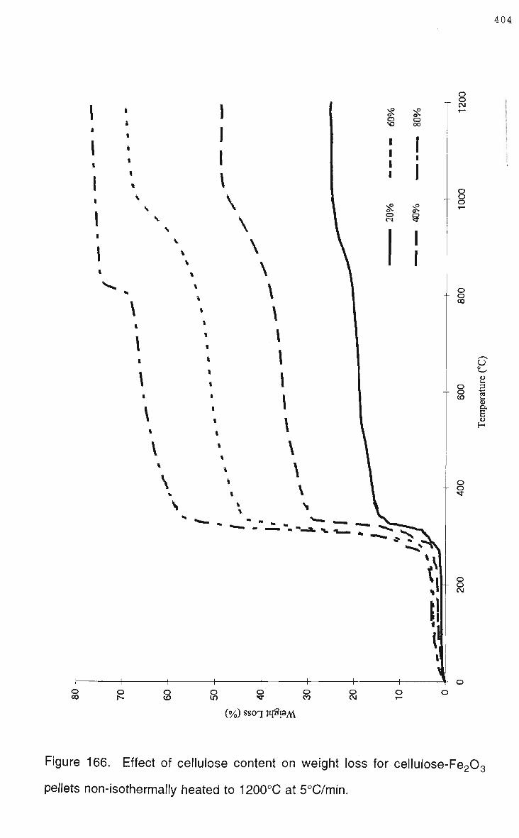
404
o o CO
O
o CM
\
\
\
\
\
\
\
o CO
o o CO
o cn
o o CO
o CM
(%) ssoq jqSraAV
Figure 166. Effect of cellulose content on weight loss for cellulose-Fe203
pellets non-isothermally heated to 1200°C at 5°C/min.

by the heating rate as shown in Figure 167. A second reaction step was also
found to become more defined as the cellulose content increased. Reacted
pellets exhibited signs of shrinkage, increasing volatile content resulted in
greater shrinkage across the pellet diameter however vertical swelling
increased. The overall appearance of the cellulose-Fe203 pellets changing
from smooth surfaces with an oxide-red colour to rough surfaces with
numerous lateral cracks, the surface having a specular-flaky texture with a
grey metallic colour. The volatile content was also found to affect pellet
strength, pellets with 20 and 4 0 % cellulose had reasonable strength and
could be readily handled after reaction, however, increasing the cellulose
above these levels had an adverse effect. Pellets with 60 and 8 0 % cellulose
after reaction were fragile and tended to crumble.
Table 50 shows the chemical analysis of the reacted cellulose-Fe203 pellets,
evident from the chemical analysis is that increasing the cellulose content
increases the metallic iron content within the pellet as shown in Figure 168.
The chemical analysis would also suggest that increasing the rate of heating
increases the degree of reduction within the sample, for samples with 2 0 %
cellulose increasing the rate of heating from 2 to 5°C/min increased the iron
as FeO from 34.4 to 52.2%.
Reaction of F e 2 0 3 with combined fixed and volatile carbon, C:Fe20 3 being
varied between 1:1 and 1:6 with a constant 2 0 % cellulose, found that the
primary weight loss curves up to 550°C, within experimental accuracy, are
similar, as shown in Figures 169 and 170, the main weight loss again
occurring in the range of 280 to 320°C. At temperatures above 550°C
reaction paths diverge, being dependant on the C/Fe203 ratio and heating rate
as shown in Figure 171.
The handling strength of the reacted pellets decreased as the fixed carbon

406
c
O
o
O O in
o o
U
o 's o 3 ci cd u
D.
E
o o CN
o o
o o O o O o CN
(%) SSOT jqSraM
Figure 167. Effect of heating rate on weight loss for a cellulose-Fe203 pellet
non-isothermally heated to 1200°C.

407
Table 50. Chemical analysis of cellulose-Fe203 composite pellets heated to
1200°C.
Cellulose:Fe2Q3 Heating (°C/min) Fe° (%) FeO as Fe (%) Fe3+ as Fe (%)
20:80 5 1.2 52.2 22.1
20:80 2 <0.2 34.4 39.3
40:60 5 22.3 39.6 18.6
60:40 5 73.0 15.3 4.2

408
c CD +-<
C
o o c o o "5 +-<
CD
2
% Cellulose
Figure 168. Effect of cellulose content on the metallic iron content in
cellulose-Fe203 composite pellets after non-isothermal heating to 1200°C at
5°C/min.

409
o o CN
o o o
o o 00
o o
0
!
o o
o o CN
(%) ssoq jqSpM
Figure 169. Effect of fixed carbon ratio (C:Fe203) on weight loss for cellulose-
C-Fe203 pellets non-isothermally heated to 1200°C at 2°C/min.

\
\
o in
o o CO
o CM
(%) ssoq iq§PA\
in
—< ci o
o o
T w
o o o
o o CO
o o CO
u
cd
u o. 6 H
o o •sr
s o o CM
Figure 170. Effect of fixed carbon ratio (C:Fe203) on weight loss for cellulose-
C-Fe203 pellets non-isothermally heated to 1200°C at 5°C/min.

55
50-
w
3 45
'<D
40-
35
•
•
•
•
•
4
• 5°C7min
• 2°C/min
5 T" 6
C:Fe203 Ratio
Figure 171. Effect of the fixed carbon to hematite ratio on the weight loss of
composite cellulose-C-Fe203 pellets non-isothermally heated to 1200°C.

increased. Samples with C : F e 2 0 3 ratios of 1:1 and 1.5:1 could be readily
handled after heating to 1200°C, at higher ratios 4.5 and 6:1 the samples fell
apart while being removed from the reaction crucible. The outer surface of the
reacted pellets was similar in colour to the cellulose-Fe203 pellets, the texture
however w a s not as specular or flaky. Reacted samples again exhibited
lateral cracks which appeared more severe with increasing fixed carbon
content. Examination of broken high ratio pellets (4.5 and 6:1) revealed that
the interior was a soft black mass, considerably different to the flaky grey
material found on the surface.
Table 51 shows the chemical analysis of the reacted carbon-cellulose-Fe203
pellets, evident from the chemical analysis is that increasing the fixed carbon
content influences the metallic iron content within the pellet as shown in
Figure 172. The chemical analysis also indicated only a small difference
between the heating rates for the degree of reduction within the samples.
The weight loss curves for the type 3 pellets containing cellulose, fixed
carbon, F e 2 0 3 and fluxes as outlined in Table 42, exhibited similar behaviour.
Considerable weight loss again occurred over a narrow temperature range ,
280 to 320°C, while above 550°C the weight loss curves diverge. Figure 173
illustrates the weight loss curves for the low flux composite pellets (type 3.1)
and Figure 174 illustrates the weight loss curves for the high flux composite
pellets (type 3.2). Evident from the data is the similarity between the curves
and that the weight loss during heating is influenced by the flux content and
the heating rate. Decreasing the flux content and heating rate both resulted in
increased weight losses.
The type 3 pellets after heating to 1200°C had a surface appearance different
to the non-fluxed (type 1 and 2) pellets. The surface colour was a motley grey-
brown and the texture was relatively smooth. The outer flaky crust that

413
Table 51. Chemical analysis of cellulose-C-Fe203 composite pellets heated
to 1200°C.
C:Fe2Q3 Heating (°C/min) Fe° (%) FeO as Fe (%) Fe3+ as Fe (%)
1.5:1 5 61.6 21.9 10.0
3:1 5 73.3 12.7 2.8
3:1 2 75.8 13.0 <0.5
4.5:1 5 67.9 9.4 8.4

c CD •4—'
c o o c
e o ffl CD
80
75-
70-
65-
60
D 5°C/min
• 2°C/min
3 T" 4
nr 5
C:Fe203 Ratio
Figure 172. Effect of fixed carbon to hematite ratio on the metallic iron content
in cellulose-C-Fe203 composite pellets after non-isothermal heating to
1200°C.

(%)ssoq rqSraM
Figure 173. Weight loss for fluxed-cellulose-C-Fe203 composite pellets
isothermally heated to 1200°C. Total flux content 12.8%.

o o CN
o o o
o o oo
o o
tj
3 u.
<u a. E H
o o
o o CN
(%)ssoq jqSpM
Figure 174. Weight loss for fluxed-cellulose-C-Fe203 composite pellets non-
isothermally heated to 1200°C. Total flux content 21.55%.

appeared on the non-fluxed pellets was also absent. Figure 175 shows a side
view of a type 3 pellet which clearly shows the colour and texture of the
reacted pellet and the presence of severe lateral cracks. Preparation of
samples for chemical analysis and metallography revealed that the lateral
cracks did not appear until the pellets reached a temperature of 600 to 700°C.
Table 52 shows the chemical analysis of the reacted type 3 pellets, clearly
increasing reaction temperature increases the extent of reduction within the
sample. Chemical analysis also indicated decreasing the heating rate
favoured reduction, while increasing the flux levels resulted in a lower metallic
iron content. Figure 176 shows that increase of the metallic iron content with
temperature in the fluxed composite pellets.
The progress of reaction in the fluxed composite pellets was followed by
metallographic examination of the microstructure of samples removed at
various temperatures during non-isothermal heating in the thermogravimetric
furnace. No structural changes were observed until the 300 to 400°C range,
when the fibrous cellulose in the pellets started to decompose. The change in
the fibres was observed uniformly throughout the pellet, the cellulose fibres
changing colour, developing cracks, and loosing cohesion from the
surrounding matrix through particle shrinkage. Figure 177 shows cellulose
fibres within the fluxed composite pellet after heating to 300°C.
Optical microscopy also revealed that on a micro level components in the
pellet were not uniformly distributed. Much of the hematite appeared to have
agglomerated with the graphite and fine flux particles and were seen as island
type structures, while larger flux particles tended to associate with the
cellulose. It was also evident that pellet preparation (dry uniaxial pressing as
described in section 8.2.3) resulted in a preferred orientation within the
composite pellet, pressing generating laminations such that in the centre

418
Figure 175. Side view of fluxed-cellulose-C-Fe203 composite pellet after non-
isothermal heating to 1200°C.

419
Table 52. Chemical analysis of fluxed-cellulose-C-Fe203 composite pellets.
Sample Temperature Fe° (%) FeO as Fe (%) Fe3+ as Fe (%)
3.1 600-5°C/min 0.2 5.3 39.6
3.1 700 - 5°C/min 0.2
3.1 800-5°C/min < 0.2
3.1 900-5°C/min < 0.2
3.1 1000-5°C/min 24.6
3.1 1100-5°C/min 43.7
3.1 1200-5°C/min 49.0
3.1 1200-2°C/min 49.5
3.2 1200-5°C/min 38.0
5.8
4.6
8.3
12.2
9.0
10.0
12.0
11.4
38.6
38.4
37.0
17.3
9.5
7.2
8.3
6.7

c 2
50-
40-
30-
20-
10-
n _ n V
n M
n V
n M
•
D
0
I
ft
•
o
5°C/min
2°C7min
type 3.2 (high flux)
1 1 500 600 700 800 900 1000 1100 1200
Temperature (°C)
Figure 176. Effect of heating temperature on metallic iron content in fluxed-
cellulose-C-Fe203 composite pellets.

421
Figure 177. Microstructure of fluxed-cellulose-C-Fe203 composite pellet
showing cellulose fibres after non-isothermal heating to 300°C.

regions particles were horizontally oriented while towards the edge they were
tilted in the compression direction.
By 600°C there was a noticeable difference between the edge and top
surfaces and the inner material of the composite pellets. The inner regions no
longer displayed the characteristic red oxide colour of hematite, instead the
island structures were grey, indicating the hematite had been partially
reduced. However to a depth of approximately 1 to 2 m m around the side
and top edges of the sample little reduction appeared to have occurred as the
red-oxide colour was still prominent. Figure 178 shows the iron oxide island
structures at 600°C have yet to undergo any significant particle growth
through sintering.
By 800°C some sintering of the iron oxide particles was detected, by 900°C
small regions of metallic iron were clearly visible in the island structures as
shown in Figure 179. With increasing temperature the extent of metallisation
within the pellets increased substantially, increasing metallisation being
accompanied by the loss of integrity of the prior oxide-carbon-flux island
structures. Figure 180A shows metallic iron in the prior island structure, the
loss of integrity being clearly visible at higher magnification in Figure 180B.
The microstructures also show the reduction from F e O to metallic iron and the
preferred growth of the larger metallic particles. The reduction and particle
growth continues with increasing temperature, at 1100°C little unreduced iron
remains as shown in Figure 181. Figure 182 shows that at 1200°C large
islands of metallic iron are found in the microstructure, with numerous smaller
metallic particles dispersed through the matrix. Unlike the iron flux
components appear relatively unchanged during heating to 1200°C.
Examination of pellet temperature and side edges revealed the presence of
unreduced iron oxides upto 1200°C, regions of metallic iron and two oxides

*&¥*
Figure 178. Microstructure of fluxed composite pellet at 600°C

424
, I
f ^
Figure 179. Microstructure of fluxed composite pellet at 900°C showing
regions of metallic iron.

Figure 180. Microstructure of fluxed composite pellet heated to 1000°C at A)
low and B) high magnification.

426
Figure 181. Microstructure of fluxed composite pellet heated to 1100°C.

427
» *. •
• 0W
• •
• • \ <
4
m * • • • * « . * t
m
* m
- >• ' - $ *
a
P *• *
c ••
•
•* •
1
L 4 1 fc., ' # 4« .
L ^
#
- • .. | . . > t' "
* . ^ • • - •
r. .-. *;• . • • •» . •* • ..»,_
• «- •• • •. • • - — _ _ • • ' r . ._
ft
'• w» « ^ ^
'-<<'.^ :*-yH
•
•
k:-Figure 182. Microstructure of fluxed composite pellet heated to 1200°C
showing large continuous regions of metallic iron.

being visible as shown in Figures 183A and B. Polishing during
metallographic preparation produced surface relief on some of the metallic
iron particles, the surface relief being a result of hardness variations across
the iron particles. Etching the composite pellets revealed iron particles had a
pearlitic structure above 1100°C. Figure 184 illustrates that at 1100°C the
pearlitic structure was not uniformly distributed through the iron, further
heating to 1200°C however generated a uniform pearlitic structure as shown
in Figure 185.
Xray diffraction analysis of the partially reacted fluxed cellulose-C-Fe203
pellets support microstructural analysis in respect of the progress of iron oxide
reduction. Interpretation of the X R D data is complicated by the D-spacing
overlap of several of the components of interest (graphite and silica, hematite
and magnetite) and the low levels of the flux components, however, the
progress of reduction is clearly evident from Figures 186 to 191.
At 300°C (Figure 186) the main identified peaks are due to Fe 2 0 3 , a single
peak for graphite, and a very small peak identified as residual cellulose. At
600°C (Figure 187) the F e 2 0 3 peaks have noticeably decreased while several
F e 3 0 4 peaks have developed. At 800°C (Figure 188) F e 2 0 3 is still present,
but in decreasing amounts, noticeably the level of F e 3 0 4 has not overly
increased. Between 800 and 1000°C (Figure 189) Fe 2 0 3 , F e 3 0 4 and FeO
were all identified in the composite pellets, Figure 189 also shows the
presence of metallic iron. The spectrum of the composite pellet at 1100°C
(Figure 190) shows significant decreases in the levels of graphite matched
with increases in metallic iron. At 1200°C iron was identified as Fe20 3, Fe30 4,
and metallic iron, Figure 191 also shows that significant carburisation has
occured with a significant FeC peak being identified, this being accompanied
by a decrease in the peak height for metallic iron.

429
Figure 183. Microstructure of edge regions in a fluxed composite pellet
heated to 1200°C.

Figure 184. Etched (Nital) microstructure of fluxed composite pellet heated to
1100°C showing regions of pearlite and ferrite.

431
Figure 185. Etched (Nital) microstructure of fluxed composite pellet heated to
1200°C showing regions of pearlite.

u o O O cn
t i
'i
=o-i —
eO s3H
-=;: o co
o
o CD
. o IT)
o
o CO
o o o CN
o o CO T—
o o CN T ~
o o oo
o o T
*0isA £ Q Z 3 J
sjiqcfeio
o CN O O O CN
II |" 1 l
o o CD *~
I i | i :
O O CN T —
1 I ; 1 1
o o co
Q O •3-
o
o CO
$ o
CU J:
h-i
CN tn CD CU
a> CD Q
O O D C — </) O O •D C — »
Figures 186 and 187. X R D patterns for composite pellets heated to 300 and
600°C respectively.

u o
s s
0»d
31Il[cicjr]
o3J
03J
O
o CO
o
'-' s —
, :— --; —
y .
\ — < r
t •c _
!
a CD
o in
CD sz r-CN in CD CD
CD
a
-=,
o
o co
i o CM O
O CN
O
o CO
o o
CJ O 3 C-~ CO O O 3 C — CO
Figures 188 and 189. X R D patterns for composite pellets heated to 800 and
1000°C respectively.

o o o CN
i i , i r
o o CD T -
o o CN T -
o o CD
• ' 1 I
o o "
o
o o o CN
O
f
V>4
o CO
o 1 ^
I'—
*0£sd y~
03d
O CD CD ,C
CD CD
D»d
; t
o CN O
O CD
O O CN
O O CO
O O
CD
a
O O 3 C — KI O O 3 C — CO
Figures 190 and 191. X R D patterns for composite pellets heated to 1100 and
1200°C respectively.

435
The effect of potential catalytic agents on the reduction mechanisms in the
composite pellets was investigated using additions of 0.5 to 20wt% iron.
Figure 192 shows weight loss curves for catalyst additions between 0.5 and
2wt% compared to a sample with no catalyst. Up until approximately 950°C
the curves are almost identical, in particular considerable weight loss
occurring again over a narrow temperature range between 280 and 320°C.
Above 950°C the rate of weight loss, and therefore reaction, is greater in the
samples with the catalyst. No clear distinction from the weight loss data can
be made at the low catalyst additions, the weight loss curves being almost
identical. Although the rates varied above 950°C the final weight loss at
1200°C is similar for catalyst additions upto 2wt%.
Increasing the catalyst content above 2wt%, as shown in Figure 193, was
found to decrease the weight loss at temperatures in excess of 400°C.
However, the extent and rates of reaction can not be inferred directly from the
weight loss data in this situation because it is not possible to directly compare
samples with such a broad range of reactive species. The maximum
theoretical weight loss varying from 54.1 to 45.8wt% depending on the
catalyst content. In the absence of chemical analysis to support the raw
weight loss data the effect of the catalyst content, above 2wt%, requires data
interpretation by another technique to account for the broad variation in the
reactive species.
The appearance of the reacted catalyst containing samples was similar to the
cellulose-C-Fe203 pellets. The handling strength of the pellets was weak
below iron additions of 10%, the pellets often broke apart on removal from the
reaction crucible. Composite pellets with higher additions of iron (10 and
20wt%) had reasonable strength and could be handled.

436
<n N= o O O O —' CN I i
o o CN
o o o
o o 00
(J o
OJ
u. O 3 Q.
E
o o
o o CN
\
o <n
o o O CN
(%) ssoq rqSraM
Figure 192. Effect of catalyst content (Fe) on weight loss for cellulose-C-Fe203
composite pellets non-isothermally heated to 1200°C at 5°C/min. Catalyst
content 0 to 2wt%.

o m
o o CO
o CN
N: O s o
©' CN
O
•". °. O © CN — I
O
o CN
o o o
1
o o 00
o
s
3
o E H
o o •5f
o o CN
(o/0) ssoq jqSraM
Figure 193. Effect of catalyst content (Fe) on weight loss for cellulose-C-Fe203
composite pellets non-isothermally heated to 1200°C at 5°C/min. Catalyst
content 0.5 to 20wt%.

438
Chapter 10 Discussion
10.1 Bath Smelting of Composite Waste Pellets.
Bath smelting of composite waste pellets has been investigated for a single
vessel reactor. Smelting and thermogravimetric experiments have been
supported by theoretical modelling which has enabled smelting mechanisms
and kinetics to be determined. Critical process reactions for the bath smelting
of composite pellets were identified as:
- thermal decompostion of volatiles
- direct reduction and carburisation of iron within the pellet
- pellet melting and dissolution
- reduction of dissolved oxides in slag.
Composite pellets undergo similar smelting reactions to that occurring with
oxide/ore pellets with the added complexity of internal reduction due to the
presence of carbon in the pellets. As identified in the literature survey of bath
smelting technologies the predominant reduction reactions are process
dependant, the distinguishing feature of composite smelting is the extent of
internal reduction and the subsequent low levels of slag foaming.
A composite pellet charged cold to a single vessel bath smelting reactor will
heat by convection and radiation during free fall through the gas space above
the bath. Heat transfer for commercial size feed is controlled by internal
resistance, the resulting temperature profile being exponential, and size
dependant. Heat transfer modelling has established that significant volumes
of the feed material are heated to reaction temperatures during the falling gas
region. Figure 194 shows the predicted temperature profile plotted with
relevant process reactions.

439
O o
** CO i_
(D Q.
E CD
I -
1500 -
1250 -
1000 -
750 -
500 -
250 -
-
0-
F e 2 0 3
reduction
cellulose decompostion
free _ water ^____——-^^^^
> I ' I
yy
- * /
i - i " r 0
centre
0.2 0.4 0.6
Radial position (r*)
0.8 1
surface
Figure 194. Predicted temperature profile of a 1.5cm diameter composite
pellet after falling 1m through gas space in a bath smelting reactor at 1500°C.
The temperature of significant reactions in the composite pellet being: 1)
above 100°C for vaporisation of free water; 2) above 280°C for thermal
decomposition of cellulose; and 3) above 550°C for reduction of Fe203.

440
Depending on the waste carbon source considerable thermal decomposition
via pyrolysis will occur during the falling gas region. The thermogravimetric
studies showed that cellulose, used as a surrogate waste carbon to replicate
sewage sludge, underwent considerable thermal decomposition in the 280 to
320°C temperature range, which is typical for the pyrolysis of cellulose [247-
250].
The thermal decomposition behaviour of sewage sludge and other waste
organics will be different to that of cellulose, and highly source dependant.
Typical decomposition temperatures (for distillation purposes) for sewage
sludge are in the range of 250-450°C [251,252], while minimum char residues
have been found at pyrolysis temperatures ranging from 350 to 800°C
[251,253].
Given that pyrolysis is a complex series of reactions, highly dependant on
carbon type, the effect of heating on thermal decomposition and subsequent
charring during the falling gas region will vary according to the waste carbon
source. Pyrolysis and gasification of carbonaceous materials have been
extensively investigated [254], it is known that particle size, heating rates and
temperatures influence volatile yield as well as the C:H ratio in the resulting
char. Inorganic matter such as alkali metals and compounds, Lewis acids,
and transitions metals can also have large effects on the pyrolysis behaviour,
the extent of any catalytic or retardant contribution being dependant on the
chemical structure of the carbonaceous material.
Notwithstanding the differences between cellulose and real waste carbon
sources, cellulose serves well as a model compound. Predicted temperature
profiles for a 1.5cm diameter composite pellet show that the outer 7 8 % of the
pellet volume will be above 320°C after falling through a 1 m gas space above
the smelting bath, as shown in Figure 194.

Much of the volatile material is driven off during the falling gas region, only the
very inner regions of the pellet will not have been sufficiently heated for
thermal decomposition to occur by the time the composite pellet reaches the
slag bath. The residual char content will depend on the fixed carbon content
of the waste carbon and the heating rate, given the high rates of heating
during the charging period the volatile yield will be greater than that
determined in standardised tests [9]. Thermogravimetric analysis also
showed that charring was influenced by the presence of non-volatile material
and the porosity of the pellet. Proximate analysis [255] of the cellulose
showed a high volatile matter content (>98%) and a low fixed carbon content
(<2%). Proximate values clearly depend on the carbon source, sewage
sludge having a volatile matter content between 50 to 9 0 % and a fixed carbon
content of 2 to 1 0 % [251,253,256,257]. Pilot plant smelting trials of the
EnvlRONment process showed that optimum levels of sewage sludge were
25-30%, at this level the outer regions of the composite pellets would only
contain 1-2% residual fixed carbon originating from the sewage sludge on
reaching the slag bath.
Given that 6 0 % of the outer volume of the composite pellet has a predicted
temperature greater than 550°C it is feasible the pyrolysis gases (CH4, C O
and H2) would to some extent, along the pores of the pellet, reduce F e 2 0 3 to
Fe 30 4 . The extent of reduction within the composite pellet due to the high
volatile waste carbon is dependant on a number of factors. These have been
recognised to be the kinetics of reduction, the temperature gradient within the
composite pellet, the distribution of waste carbon within the composite pellet,
and the pyrolysis behaviour of the waste carbon.
A composite pellet top charged to a single vessel bath smelting reactor
generates sufficient momentum during the falling gas region that it partially
penetrates the slag layer. Observation of smelting trials revealed that pellet

442
momentum is quickly lost, bouyancy forces rapidly expelling the pellet to the
slag surface unwetted. Increasing the momentum was not found to have any
discernable effect on smelting kinetics. In many ways the composite pellets
have similar behaviour to the addition of coal to a bath smelter, coal has been
found to float on the slag, remains unwetted, and undergoes significant
devolatilisation during the falling gas region [158], calculated thermal
properties of the composite pellet, however, are much lower than coal.
Composite pellets were found to have excellent heat shock resistance with no
signs of catastrophic failure during smelting trials. Lateral cracks observed
during thermogravimetric studies can be explained by the variation in
consolidation pressure that is typical with dry uniaxial pressing [258]. The
thermogravimetric studies also showed that the friable nature of composite
pellets after heating was chemistry dependant. This has implications as far as
extending single vessel smelting to include a preheating or prereduction
stage. Off gas dust generation rates from the 100kg D C arc pilot plant trials
are relatively low to comparative bath smelting and pyrometallurgical waste
treatment technologies, showing that composite pellets have definite
operational advantages compared to feeding iron oxide pellets and carbon
separately. The low dusting rates can be explained by strength characteristics
imparted by the high volatile waste material and the high levels of porosity
within the composite pellets. The volatile waste material providing sufficient
binding strength to withstand thermal shock on initial contact with the hot
smelting gases. The strength characteristics of volatiles such as cellulose and
its derivatives (peridur) have been investigated at length for their binding
properties [228,229,231]. Specifically, the EnvlRONment process composite
pellets were measured to have a dry compressive strength of 156N, however,
more importantly composite pellets were observed to deform plastically.
Structural integrity is maintained after thermal decomposition of the volatiles
because of the high levels of porosity within the composite pellets. The
importance of pellet porosity, and its control, on strength has been realised in
commercial operations, particularly for drying and prereduction stages [55].
The initial stage of the bath smelting reaction is often associated with an
incubation period. In the smelting of ore pellets, and in dissolution studies, the
observed incubation period is explained by the finite time taken to melt an
immersion crust which formed on the object during initial contact with the melt
[125,131,132]. Experimental observations and heat transfer calculations for
the composite pellets support the notion that a slag immersion crust is not
formed during the initial contact between the pellet and slag. The composite
pellet was not wetted by the slag, microscopy revealed no slag ingress into
the pore structure, and heat transfer predicts the pellet surface is at the slag
temperature. The observed incubation period is therefore unlikely to be due
to the melting of a slag crust, but simply the time taken for sufficient heat to be
transferred into the pellet for reduction reactions to become active enough to
agitate the slag. Because the majority of the pellet sits above the slag bath
considerable portions of off gas from the composite pellet will vent without
coming into contact with the slag and it is therefore difficult to quantify an
incubation period merely by visual observation. It is also worth commenting
that the presence of immersion crusts so often observed in smelting and
dissolution studies is most likely an experimental phenomenon and would not
occur in an industrial size process. Small laboratory crucibles have low
thermal mass, while the addition of a cold object with no preheating is not
realistic. The combined effects of low thermal mass and cold pellet additions
was most apparent in the Xray smelting experiments where the larger pellets
drew sufficient heat from the reaction crucible to solidify the slag. Heat
transfer modelling of dissolution predicts that the degree of preheating
influences crust formation, the greater the preheating the thinner the crust
[125,131]. Heat transfer modelling of the single vessel reactor predicted
significant heating of the pellet in the falling gas region which makes the

addition of a pellet to an open crucible, with little opportunity of preheating, an
unrealistic model of a real process.
Internal reactions within the pellet during smelting are significant, the 2 main
reactions being the thermal decomposition of remaining volatile components
and reduction of oxides. The effect of pellet chemistry, in particular the carbon
content, can be inferred from the thermogravimetric studies. The
thermogravimetric studies provide an indication of reaction temperatures and
potential influences on the extent and rates of reaction which could not
accurately determined from the smelting experiments and are discussed in
detail in section 10.2.
The development of ferrous bath smelting technologies has identified that slag
foaming is a potential process limitation [8,259], in contrast to other
technologies slag foaming and its control has been revealed by this study not
to be a critical issue for composite pellets; smelting which was observed to
occur without excessive slag foaming. Smelting experiments using Xray
techniques to monitor the progress of reaction revealed although the slag was
agitated and turbulent during reaction it did not foam to any great height.
Similar observations were m a d e during pilot plant trials in the 100kg D C arc
furnace. Laboratory smelting experiments revealed the extent of agitation
provided by reaction off gases was limited to approximately a 3 0 m m
circumference around a 1 5 m m diameter pellet. This m a y also explain the
observation in the 100kg D C arc pilot plant trials that the slag surface was not
uniformly agitated but often had a rippled dimple like appearance.
Examination of reaction crucibles after single pellet smelting trials enabled
the extent of foaming to be physically measured due to slag erosion marks
on the reaction crucible. Using the equation
£ = XL. (32)
g

where S is the foaming index, H is the foam height and V g is the superficial
gas velocity [143], it is possible to calculate the potential slag height
generated during smelting. For a typical bath smelting slag with a low FeO
content the foaming index has been shown to have a value of approximately
2 [144]. Calculation based on the iron oxide content of the pellet predicted
that the slag should foam to a height of 3.6cm in the reaction crucible if all the
reduction of F e O occurs in the slag, measurements from the crucible
indicated the foam height only reached an average of 0.5cm. This indicates
that not all reduction occurs in the slag phase. Back calculation for the level
of foaming that was generated indicates that for the experiments only
approximately 1 0 % of the reduction occurred in the slag phase, i.e. 9 0 % of
the iron oxides are reduced within the pellet.
The experimental evidence indicating that dominant reactions for composite
smelting differ from those for oxide/ore pellets is supported by analysis of
pilot plant data from the DIOS and AISI-DOE research programs where it has
been shown that the contribution of the reaction interfaces to overall
reduction varies with the smelting vessel size, (Table 17, section 3.3.4)
[148,154]. Extrapolating the AISI-DOE and DIOS pilot plant data it is
possible to predict for the EnvlRONment process pilot plant trials the
contribution to reduction from the metal-slag interface. Assuming the
reduction mechanisms are the same as those operating in the DIOS and
AISI-DOE bath smelting processes then for the 100kg D C arc furnace
reduction at the metal-slag interface accounts for 60-100% of the total
reduction as shown in Figure 195. At such high contributions slag foaming
would be considerable as the majority of reaction gases would evolve at the
bottom of the slag layer. Observation of pilot plant smelting trials clearly
showed this not to be the case, therefore supporting the notion that reduction
does not primarily occur in the slag phase.
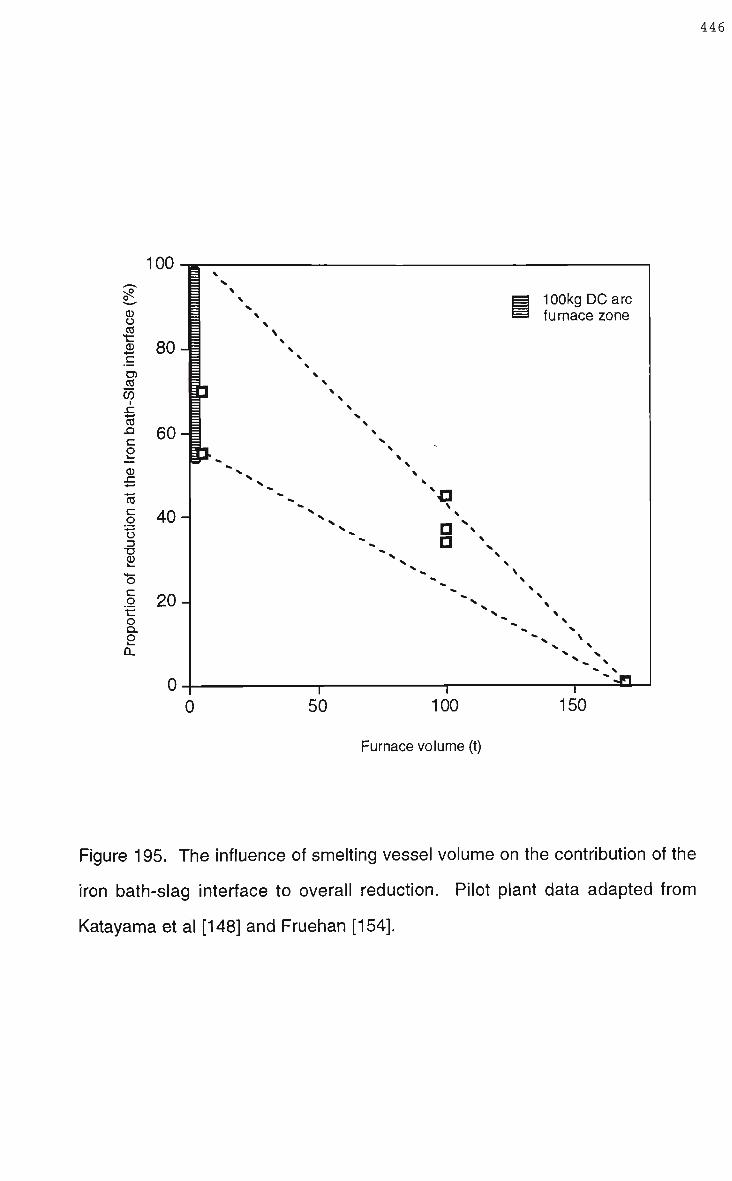
^^
CD O CO t CD •4—i c • ^
D) CO CO .C 4—' CO
2 CD .C
c o '•4—'
Z3
o C o •c o Q. O 0.
80-
60-
40-
20-
n '
3 \ = x = \ = \
100kg D C arc 1 * ^ furnace zone = \ = \ = \ = X
i \ = \ = %
P = x = v = x = \
K N X
"* N 1-1
D * D \
* \
X \
* » X - v \
"» X
~JH 1 1 i
0 50 100 150
Furnace volume (t)
Figure 195. The influence of smelting vessel volume on the contribution of the
iron bath-slag interface to overall reduction. Pilot plant data adapted from
Katayama et al [148] and Fruehan [154].

Further experimental evidence that the majority of reduction occurs within the
agglomerated feed was found when smelting trials were examined with Xray
radiography. Xray images taken during smelting show the existence of
dense spherules within the composite pellet well before the completion of
smelting-reduction. Characterised partially smelted pellets, recovered
typically after 45 seconds from laboratory trials, suggest these spherules to
be metallic iron. Given the poor resolution of the Xray unit it is reasonable to
assume that considerable portions of the pellets were metallised with only
the larger spherules being identified. Microscopy indicated that ablation of
the composite pellets occurs partially through the dissolution of F e O but
primarily via the loss of metallic iron, iron droplets coalescing on the outside
of the pellets before separating off and descending through the slag layer.
To illustrate the potential extent of the iron-slag reduction reaction the
interfacial area of the iron droplets was calculated. Based on microscopy of
the partially smelted pellets, feed rates from the 100kg D C arc pilot plant
trials, and typical smelting rates the steady state interfacial area was
calculated at 36m2. This compares to a value of 2600m 2 calculated for the
DIOS plant that utilised bottom gas injection and a production rate of 40
tonne per hour [127], a rate nearly 3000 times that of the composite smelting
trials.
In deep slag processes such as DIOS and AISI-DOE the interfacial area of
iron droplets is dependant on the slag weight and bath agitation via bottom
injection. In composite smelting it is clear that large interfacial areas can be
achieved without bottom gas injection.
Microscopy and selective etching clearly revealed that the iron present in the
pellet is significantly carburised during smelting, that is much of the iron is
carburised within the pellet before it is completely dissolved. The

thermogravimetric studies showed that carburisation of the metallic iron in the
composite pellets w a s significant at temperatures of 1100°C and higher.
Diffusion calculations of carburisation depths predict exceedingly fast
carburisation rates (< 1s) at typical smelting temperatures, and the iron
particle sizes revealed by microscopy (~ 5|im).
Experimental evidence suggests that for composite smelting the main sites for
carburisation will be in the composite pellet during smelting and to a lesser
degree from char in the slag. Carburisation at the metal-slag interface may
not be significant as the iron droplets descending through the slag will be
already carbon saturated. Highly carburised iron microstructures were
revealed by examination of reduced iron from smelting trials in which outside
sources of carbon, such as clay-graphite crucibles and iron heels were
avoided.
Pellet ablation in composite smelting occurs via dissolution and melting, this is
in comparison to the in-slag smelting of oxide pellets where pellets purely
undergo dissolution [133]. In composite smelting the unreduced iron oxides
dissolve into the slag and reduced iron melts, the melting temperature
depending on the degree of carburisation, the extent of either reaction being
dependant on the rate of reduction within the pellet. If the rate of reduction is
fast the majority of pellet ablation will occur via melting, while if the rate is slow
a far greater amount of the pellet will ablate through dissolution of the oxides
into the slag. Microscopy revealed that both mechanisms operated parallel,
and ablation via melting was dominant towards the end of smelting. This
would explain the sudden decrease in slag agitation observed in the smelting
trials also at the end of smelting, that is iron is mainly present in metallic form
towards the end of smelting.
Heat transfer modelling predicted a melting time of 92s for a 1.5cm diameter
composite pellet. The predicted melting time lies in the range of values

observed during all the preliminary, pilot plant and laboratory smelting
experiments. Real smelting times differ because the assumptions required to
develop the model oversimplify the smelting process. In particular the model,
as do many other similar heat transfer models [131,133,158,213], assume the
pellet is fully submerged. The effect of varying heat transfer to the pellet was
most obvious in the laboratory smelting experiments were the smelting times
were considerably longer than the 100kg D C arc pilot plant trials. Variations
in the chemistry of the waste composite pellets, particularly the metallic iron
content, would also give rise to differences.
The reduction of oxides dissolved in slag only plays a minor role in overall
reduction. Estimates from the smelting trials are about 1 0 % of the entire
reduction occurs via this mechanism. As the composite pellet ablates
unreduced oxides at the pellet-slag interface dissolve into the slag, where
they are then reduced via presumably the 2 recognised mechansims, char in
slag and carbon in iron droplets [9]. Observation of the composite smelting
trials suggest that this occurs in close proximity to the pellets. Slag agitation is
localised, this is thought to be because the pellets smelted were self fluxed, as
they ablated the fluxes together with the iron oxides and residual fixed carbon
flowed out of the pellet in a stream. Reduction of the oxides is most likely to
occur in this region. This is supported by observations which showed gas
bubbles rising from the slag streams and the presence of metallic spherules,
the further out in the stream the less the gas bubbles and the greater the
appearance of the iron droplets. If this mechanism does operate it would
further explain the low levels of slag foaming. It would also mean that in the
immediate vicinty of the pellets the slag chemistry has large chemical and
therefore physical property gradients. This is in comparison to bath smelting
of ore pellets where dissolution is followed by reduction of oxides from the
slag by char and carbon in iron droplets and is dependant on the extent that
these circulate through the slag [138]. In composite smelting the reductants

450
are forced together, even if the kinetics do not favour complete internal
reduction within the pellet, the initial stages of pellet dissolution favour the
close proximity of carbon suitably for reducing the iron oxides.
Following the argument that in the immediate vicinity of the smelting pellet the
FeO content is relatively high, and that the only source of carbon in the system
also originates from the pellet, thus eliminating reagent starvation, it is
reasonable to expect high reaction rates close to the smelting pellets. The
chemical gradient thus being reflected in a rate gradient which decreases with
distance from the pellet. In a well mixed composite pellet, ignoring the char
from pyrolysis of the volatile components, the ratio of fixed carbon to iron
oxides will remain throughout smelting, since both are consumed at equal
rates. The stream of dissolving F e O will contain sufficient carbon for
reduction, this ratio will stay constant as F e O reduces in the stream. If the rate
of reduction of the dissolved oxides is purely due to char in slag then it will
decline linearly with distance from the pellet. However, it is reasonable to
speculate that given the high degree of metallisation within the pellet a large
number of small metallic iron droplets will also be in the stream. Reduction
from carburised iron droplets will also be significant. The presence of metallic
iron has been found to increase as smelting proceeds, this means that
although the localised F e O content will decrease as smelting proceeds the
iron droplet content will increase. As the reduction of dissolved oxides is
influenced by the amount of char, iron and F e O in the slag it can be seen that
the rate will change not only with time but position, as the relative amounts of
iron, char and F e O do not remain constant.
In comparison to bath smelting of oxide pellets the slag layer is only complex
along the surface, identification of the reduction mechanisms and that the
majority of reduction occurs within the pellet would suggest that underneath
the top layer the slag is not complex. It is also clear that unlike other process

451
bath smelting of fluxed composite pellets the slag layer is merely a heat
source rather than the major reaction site.
In the bath smelting of composite pellets reduction of iron oxides have been
identified at 3 sites:
- the interface between oxides dissolved in slag and char
- the interface between oxides dissolved in slag and iron droplets
- internal direct reduction within the composite pellet.
The reduction of dissolved oxides from slag by char is known to be controlled
by mass transfer of FeO, the rate being proportional to the FeO content of the
slag, similarly the rate of reduction by carbon in iron droplets is also
proportional to the F e O content of the slag. The rate of reduction in the slag
given by the rate equation [3] as:
R = (kmA m + kcAc)(%FeO) (122)
where km is the rate for the iron-slag reduction reaction, kc is the rate for the
char-slag reaction, and A m and A c are the surface areas of iron droplets and
char in slag.
To account for the third reaction site, internal direct reduction, a third rate term
is added to equation 122. The rate for the non-slag reduction being
dependant on the rate of internal direct reduction (kj r) and the rate of pellet
ablation (D). Therefore the overall rate is expressed as:
R = (kmAm + kcAc)(%FeO) + (kLr)(D) (123)
It is apparent from equation 123 that the overall rate of reduction in the bath
smelting of composite pellets can be increased by increasing the char and

452
iron droplets in the slag and by increasing the extent of internal direct
reduction.
Reaction mechansims for the smelting of composite pellets can not be
described by a single model. Visual observation of smelting would indicate
that overall smelting follows the classical topochemical model, however,
characterisation of the pellets which have been removed from the slag during
smelting indicate smelting behaviour is more complex. The entire reaction
system is complex because smelting involves parallel liquid phase and solid-
gas reactions. Pellet smelting was found to occur with behaviour intermediate
between the shrinking core model and the uniform conversion model [260].
Cross sectioning of the pellets revealing a diffuse reaction front, porosity was
also observed to increase during smelting, due to thermal decomposition of
the volatile organic, indicating that aspects of the smelting reaction may also
be represented by the crackling core model. The reaction front indicates that
within the composite pellet a temperature gradient exists during smelting, and
that the reduction of the oxide is multistep, the different stages of the reduction
of Fe 2 0 3 to Fe occurring in parallel. This supports the heat transfer model
which calculated that pellet heating was controlled by internal resistance and
as a consequence has steep temperature gradients. The ingress of the
reaction front was not uniform but clearly exhibited a weighting towards the
slag-pellet interface, particularly during the early stages of smelting. This
again supports conclusions from the heat transfer model which determined
that heat transfer to the composite pellet would not be uniform during smelting
as it is exposed to 2 different fluids, the slag and the furnace atmosphere, the
model predicting greater heat transfer from the slag than the gas. The
considerable influence of heat transfer on the smelting of composite pellets is
best illustrated by the smelting experiment observations that by forcibly
immersing the pellet, so as to increase heat transfer, the smelting reaction
became considerably faster.

The experimental investigation of composite bath smelting, and the supporting
literature survey of bath smelting, makes it possible to evaluate the rationale of
adding a carbonaceous material to a bath smelter as an integral component of
the feed material. The addition of carbon to the bath smelting reactor as a
integral component of the feed material offers several potential advantages to
adding carbon separately. Adding carbon in such a manner is likely to assist
in the melting of the flux components, the presence of even small amounts of
carbon are known to help the melting of mould flux powders in casting
technology [261]. Composite pellets are a practical way of using carbon fines,
fines which otherwise might not be suitable, in effect this also controls the
upper size of char in the process since carbon is only added as a component
in the composite pellets the size of the char is by logic smaller than the pellet
size. Carbon size is known to influence both reduction and carburisation. The
presence of carbon in the pellets may also explain their nonwetting behaviour.
The non-wetting behaviour is unlikely to translate to control of slag foaming in
a real process. Based on typical feed rates for the 100kg D C arc pilot plant
trials the calculated surface area coverage is less than 1%. To achieve the
levels of surface coverage required to influence slag foaming would require
increased feed rates. However, in practise these are not attainable because
the large volumes of off gas generated during smelting, due to the high
volatility material, is problematic.
10.2 Direct Reduction of Composite Pellets.
The dominant reduction site in composite smelting is the direct reduction that
occurs within the pellet. Direct reduction was studied using non-isothermal
thermogravimetric techniques, thermal analysis via this route was chosen as it
was thought this would provide the best m e a n s to investigate reaction
temperatures and potential influences on the extent and rates of reaction

which could not accurately determined from the smelting experiments, the 2
main reactions being the thermal decompositon of the volatile component and
reduction of the iron oxides.
For non-isothermal heating, sequential reactions are often associated with the
appearance of steps in the reaction curves [262], these steps can be seen in
the weight loss curves shown in section 9.3.2. Structural characterisation of
the samples indicated that reaction overlap and poor temperature uniformity
had been successfully avoided by using slow heating rates; (linear rates of 2
and 5°C/min). Microstructural examination of the surrogate composite pellets
indicated sequential reduction of F e 2 0 3 had taken place, apart from the outer
edges of the samples. In these regions it was evident that the ingress of N 2
(furnace carrier gas) was sufficient to upset the C O / C 0 2 balance, inhibiting
reduction. The intrusive nature of inert carrier gases has been considered by
others, although often it is simply assumed to have negligable effect to allow
kinetic rate constants to be determined [3,29,263]. The effect of the carrier gas
ingress into the structure during reduction is also evident from the X R D
patterns and chemical analysis which show more than 2 iron species co
existing in the samples at a time.
In general, the weight loss curves suggest the onset of reduction was
relatively unaffected by the variables tested, however, the extent and rate of
reduction were influenced by pellet chemistry. Analysis of the data indicates
that below 650°C little reaction occurs apart from moisture loss and pyrolysis
of the volatile organics. Reduction of F e 2 0 3 to Fe° was possible using
cellulose as the only source of carbonaceous reductant, reduction occurring
either due to cellulose charring or from pyrolysis gases. Inspection of the
reaction curves shows that the main weight loss occurs between 280 and
320°C, this corresponds with typical temperatures for the decomposition of
cellulose [247-250]. It is clear that the thermal decomposition of the cellulose

455
is affected by the heating rate as well as the presence of secondary non
volatile material.
The reaction curves also provide an indication of temperature for the evolution
of gaseous pyrolysis products; for cellulose the maximum C O output is
generally associated with thermal breakdown [249]. As thermal
decomposition of cellulose was found to be 9 0 % complete by 500°C,
reduction of F e 2 0 3 by pyrolysis gases would be minimal.
Trials during development of the EnvlRONment process have shown that
carbonaceous material with high volatility is difficult to process with feed
containing more than 3 0 % . In operating practice the loss of potential
reductant through the pyrolysis of volatile carbonaceous material has been
overcome by the use of supplementary carbon. Additions are dependant on
waste chemistry, sufficient fixed carbon being added to the pellets to ensure
complete reduction and bath carburisation.
The establishment of rate laws, or even the extent of a reaction, is difficult to
infer directly from thermogravimetric weight loss data for direct reduction,
particularly when a system contains more than 1 reductant. The measured
weight loss arises due to a combination of the reduction of iron oxides and
oxidation of carbon. Several techniques are available to monitor the progress
of reaction, the 2 most widely adopted being the use of a psuedo-kinetic
parameter (/) and chemical analysis of reaction products. Chemical analysis
of the reduction products is typically expressed as a degree of reduction (a).
The use of the psuedo-kinetic parameter / in kinetic equations, although
widely used, is only semi-empirical, however the measurement of / can be
done continuously rather than a which requires numerous samples and time
consuming chemical analysis.

A reaction balance was found to exist between the ratio of volatile material
and hematite, Figure 196 shows the effect of cellulose content on the degree
of reaction (/), where /, a psuedo-kinetic parameter, is typically defined as per
the following equation [264]:
, _ wt loss at Temp T (-\OA\ J maximum possible wt loss * '
where the maximum possible weight loss is the total oxygen content in the
oxide + total moisture + total volatile matter + total fixed carbon.
Increasing the volatile content increased the amount of potential
carbonaceous reductant, however, the accompanying decrease in hematite
encouraged more complete gaseous pyrolysis of the cellulose. The fibrous
nature of the cellulose creating porosity in the pellets during decomposition,
as volatile content increased offgasing was much less restricted, resulting in a
lower degree of charring. In the extreme case where cellulose was heated on
its own no charring was evident.
Qualitative analysis of the reaction curves (/) showed that as the volatile
content increases the amount of oxygen removed from F e 2 0 3 increases,
before falling away sharply at a content of 6 0 % . The effect of heating rate is
less pronounced, the heating rates were relatively slow which may account for
the small difference observed between reactions. In general it was found that
initial cellulose decomposition via pyrolysis was encouraged by increased
heating rates, however the effect on overall reaction is masked by the greater
influence of the volatile content.
Calculation of the amount of oxygen removed during reaction, as indicated by
chemical analysis of the iron species, supports interpretation of weight loss
curves in that increasing the volatile content increases the amount of volatile

0.9-
^ 0.8-
s o •s 0.7H u s cu © 0.6-eu cu en cu ^ 0.5-1
0.4-
0.3
J-"-'"' /#
^,.-' --*
"* ++ **
/* y n*" .*' /r
,* »'
.-* ..-.....<>•
. - - - '
,..'*'
******
I*****'
.o
...o
o c CN
I o
o 00
Cellulose (%)
Figure 196. Effect of celluose content on direct reduction as determined by
thermogravimetric analysis.

458
matter not utilised in reduction. Figure 197 shows that increasing cellulose
content results in the balance of thermal decomposition shifting to lower levels
of charring. At 2 0 % cellulose additions the level of charring is estimated at
22%, while at 6 0 % charring has fallen to 13%, increased reduction occuring
because of the greater initial cellulose content as shown in Table 53.
Chemical analysis also revealed that the cellulose-Fe203 samples after
heating had essentially no residual carbon (%residual C = 100 - Fetota|). This
suggests that, given the levels of unreduced oxides, reaction for the cellulose-
Fe 2 0 3 samples was controlled by reagent starvation.
Reduction of Fe203 by combined fixed and volatile carbon, C:Fe203 being
varied between 1:1 and 6:1 with a constant 2 0 % cellulose, found that the
primary weight loss curves up to 550°C, within experimental accuracy, are
similar. This supports the notion that no smelting-reduction reactions occur
below this point apart from the thermal decomposition of volatiles. At
temperatures above 550°C reaction paths diverge, being dependant on the
C:Fe203 ratio and heating rate. The weight loss curves show that maximum
weight is lost for the 3:1 ratio, at lower C:Fe 2 0 3 ratios reagent starvation
minimised weight loss as does residual carbon for C:Fe20 3 ratios in excess of
stoichiometry. A similar pattern was measured for both heating rates (2 and
5°C/min).
Initial examination [265] of the reaction parameter / as defined in equation
124 highlighted shortcomings in this method of calculation. The reaction
parameter / is ambiguous for carbon levels above stoichiometry, the
calculation method leading to errors and underestimation of the extent of
reaction. The problem arises due to the assumption that all the carbon can be
consumed, reduction of pellets with carbon in excess of stoichiometry
produces pellets with residual carbon. This was accounted for by modifying
the calculation of /, the modified reaction parameter /' being:

^5 c£ •o CD >
o E CD
CD
X
o
90 n
80-
70-
60-
50-
40-
30-
20-1 0
s
•s,
s
s s
^•--.
1 1 1
20 30 40
/
50 60
r-30
-20
-10
n
70
CD CO
"CD
o H—
o c i_
CO
o
CD ^^ CC E CO UJ
% Cellulose (remainder Fe203)
Figure 197. Calculated oxygen removal and cellulose charring levels; based
on chemical analysis of cellulose-Fe203 pellets heated non-isothermally to
1200°C.
Table 53. Char levels from thermal decomposition of cellulose in cellulose-
Fe 20 3 pellets.
% cellulose 20 40 60
% charring 22.2 14.9 12.7
total char in 3g pellet (g) 0.133 0.179 0.229

wt loss at Temp T maximum possible reaction wt loss (125)
where the contribution of carbon to the maximum possible reaction weight
loss is limited to that required for complete reduction. The resulting degree of
reaction (/) curves for the non-isothermal heating of cellulose-C-Fe203
pellets are shown in Figure 198. Evident from the reaction curves is that
increasing the fixed carbon level increases the extent of reaction.
However, the effect of carbon ratio or the heating rate on reduction progress is
not clear when the reaction curve is expressed differently as shown in Figure
199. Contrary to the majority of reduction kinetics studies of composite pellets
which show rates of reaction increasing with carbon content [23,29,266] no
discernable increase was evident when the degree of reaction was calculated
using equation 125 and expressed so as to find a distinct relationship
between the ratio of C:Fe203, temperature, and the extent of reduction.
An attempt to perform kinetic analysis to determine activation energies from
the degree of reaction (/) curves for the type 1 and 2 (cellulose-Fe203 and
cellulose-C-Fe203) samples revealed another complication to the system.
The degree of reaction as calculated in equation 125 does not truely account
for the reaction path of volatiles during reduction of composite pellets.
Chemical analysis of the simple cellulose-Fe203 pellets showed that thermal
decomposition via pyrolysis generates a reducing and non-reducing
component from the cellulose. If the reaction of primary concern is reduction
of iron oxides then the degree of reaction as calculated in equation 125 needs
to be modified further to account for the non-reducing component of the
cellulose. To allow for kinetic interpretation of the reduction reaction the
degree of reaction is defined as:

\ \ \ • • * N
'. i !
• » 1
vs.. \
u o i—
=5
u o.
E W
H
ON
o 00
o r-©
lO
o in ©
"* ©
CO
o CN ©
(j) UCHPB3J JO 39J83Q
Figure 198. Degree of reaction curves for cellulose-C-Fe203 pellets with
varying C:Fe203 ratios, / calculated using equation 125.

•
0
o
A
CO
$
;,;„!
V
B
•
800°C-2°C/min
800°C-5°C/min
900°C-2°C/min
900°C-5°C/min
1000°C-2°C/min
1000°C-5°C/min
1100°C-2°C/min
1100°C-5°C/min
1200°C-2°C7min
1200°C-5°C7min
I I I I I I
1 2 3 4 5 6
C:Fe203
Figure 199. Effect of temperature, heating rate and C:Fe203 ratio on reduction
as indicated by the modified fraction of reaction parameter /' (equation 125).
Direct reduction determined using thermograviemtric analysis.

463
f_ wt loss due to reduction at T e m p T maximum possible wt loss for reduction
where the weight loss due to reduction is the loss of oxygen from the oxides +
the loss of volatile material which acts as a reducing agent (i.e. char
contribution from the pyrolysis of cellulose) + the carbon consumed in the
reduction of the oxides. As with equation 125 the total carbon consumed in
reduction is assumed to be limited to the stoichiometric requirements for
reduction.
For the cellulose-Fe203 pellets the char contribution from the cellulose is
given in Table 53, for the remaining pellet chemistries trialled, where a
constant cellulose additon of 2 0 % was used, it was assumed that the char
contribution was 2 0 % , i.e. 8 0 % of the cellulose content is lost during thermal
decomposition and does not reduce iron oxides. The effect of allowing for the
non-reducing component on the appearance of the degree of reaction curves
is shown in Figure 200 for the cellulose-C-Fe203 pellets. The curves show
that the carbon content influences the rate and extent of reduction, the greater
the carbon content the more reduced the iron oxides. The corrected degee of
reaction curves in Figure 200 suggest that reduction starts at approximately
400°C. However, the practical temperature for the reduction of hematite is
generally higher, given that for the 6:1 and 4.5:1 ratios a degree of reaction
greater than 1 is predicted would suggest that the assumption of the amount of
cellulose contributing towards reduction was incorrect. The predicted degrees
of reaction appear 1 0 % too high because of the point at which the reaction
curves divert, which is also approximately the known temperature for
reduction. Without full chemical analysis it is difficult to derive a more
meaningful interpretation of the reduction reactions. Even using chemical
analysis, to base the assumption regarding the extent of which volatile
components contribute to reduction, it is difficult to derive meaningful reaction

464
— t —
o ©
00
o ©' o © © © CN ©
CJ
3
a i-
O.
g <o H
o © CN
(j) U01PB3J jo asaSsQ
Figure 200. Degree of reaction curves for cellulose-C-Fe203 pellets with
varying C:Fe203 ratios, / calculated using equation 126.

465
curves. Figure 201 shows reaction curves for cellulose-Fe203 pellets. If the
curves are assumed to be correct they suggest that increasing the volatile
content not only increases the extent of reduction but that the onset of
reduction is shifted considerably.
Clearly the reaction system involving 2 sources of reductant, reductants which
have considerably different volatilities, is complex and difficult to make
assumptions which can be used to derive kinetic data such as activation
energies.
The complexity of studying iron oxide-carbon systems under reducing
conditions is widely acknowledged [264,267,268], but despite the extensive
array of investigations little attention has been given to the influence of the
method of calculating the psuedo-kinetic parameter (/) on interpretation of
fundamental kinetics. A cursory look at the literature reveals many different
methods for calculating the reaction parameter [28,29,264,268,269], few have
recognised the difficulty in accounting for variation in the extent of reduction
from the volatile matter.
Cypres and Soudan-Moinet [270,271] investigated coal pyrolysis in the
presence of iron oxides and found that at low temperatures weight loss was
attributed to devolatilisation of the coal and not reduction of the iron oxides.
While Dutta and Ghosh [25] studied reduction of ore-coal composites and
found that the devolatilisation of coal resulted in a low temperature non-
reducing component and a high temperature reducing component. Although
Dutta and Ghosh allowed for the non-contributing component in their
calculation of the reaction parameter / the accuracy of the estimated extent of
reduction was variable. This was attributed to the difficulty in determining the
extent of reduction from hydrogen, which was found to contribute to reduction
in an eratic fashion.

' ' / 1 v I v ' \
\ : l I .' S? v? ^? 1 0 s o~- ev1-
\ >.
© © © CN TJ- VO
N v. \ V > \
• 1 : i
i i i
• > • s ^ \
"*"»». * \
"**•**• * \
* ** * \ *"«• V
»"V, \ .
" "^X » N. * *"v\. K, ^L % X " \N \ \ ^ \ N
A N
V N V ^ V' N \ v "*<
\ \ N
\ ", I % I » I t
1 \ 1 >
I \ \
V \ ^
1 1 1 1 1 1 1 i 1 1
© © CN
© ©
o
ON
d 00 © d d d ©
cn ©
CN
d
© © oo
©
©
o
O © CN
(j) U0IPB3J JO 33J83Q
Figure 201. Degree of reaction curves for cellulose-Fe203 pellets with
varying cellulose content, / calculated using equation 126.

The contribution of hydrogen to reduction has not been incorporated into
attempts to estimate the reaction parameter / in this body of work. Given that
cellulose is a hydrocarbon it can be speculated that hydrogen is produced
during thermal decomposition and that to some degree will reduce the oxides.
As suggested by Dutta and Ghosh [25] the variable nature further complicates
interpretation of reduction from weight loss by estimating the psuedo-kinetic
parameter /.
The uncertainties of estimating the reaction parameter / raises questions
about kinetic interpretation and subsequent calculation of energy activations.
This may partly explain the broad range of published activation energy values
for the reduction reactions in iron oxide-carbon systems.
The comments of Dey et al [28] are most apt to the discussion of the validity of
using the reaction parameter /, "estimation of the psuedo-kinetic parameter
during the course of the reaction can only provide an apparent idea about the
extent and characteristics of the reaction." While Dutta and Gosh [272] add,
".... the only satisfactory general procedure employed so far consists of
chemical analysis of the reduced mixture for total iron, metallic iron, and iron
present as Fe2+...."
Chemical analysis of the iron species means that reduction, rather than the
bulk system reaction can be monitored. One method of calculation for the
degree of reduction (a) that has been extensively used [267,273-275] is that
proposed by Chernyshev where:
„ %Fe!,. - %Fe'T a = K 1 ^ x 1 0 0 (127)
%FeTx%Fer

where K is the ratio of weight of iron to oxygen in ore; %Fe^. is the percentage
of total iron in reduced body; and %FeT is the percentage of total iron initially.
Other similar methods have been developed include those by Prakash et al
[276] and Huang and Lu [27],
Despite the wide acceptance of the cited methods for calculating a problems
were found in applying each of these methods because of volatile
components in the composite pellets. The most suitable method appeared to
be calculation of the degree of metallisation, or the extent of oxygen removal
as used by Huang and Lu [27]. The method of Huang and Lu providing better
representation of reduction as it accounts for all the progressive stages in
reduction, while the degree of metallisation only represents the extent of
reaction in respect to its final state, i.e. a sample can be highly reduced but
have no metallic iron content. Figure 202 shows comparisons of reduction
and metallisation for ore-coal samples from the study of Bryk and Lu [24] and
for the cellulose-Fe203 pellets in this study.
The immediate concern with the degree of reduction methods is that they all
are heavily influenced by the accuracy of the chemical analysis which
determines the extent of the iron species in the partially reduced samples.
Material segregation of metallic spherules and low sample weights all
diminish the ability to accurately determine the iron speciation [277]. A mass
balance for iron on the samples used in the chemical analysis shows an
average difference in total iron of 4 % which sets the upper limit of accuracy of
the method. Given that the calculated deviation in some samples was as
great as 1 0 % use of the chemical analysis to determine the degree of
reduction (a) will give an indication of reduction, but it is unlikely the data
could be fitted to a kinetic equation with any great confidence.

100
UJ UJ
cr o UJ Q
O Q UJ
cn
8 0 - reduction
60
40
20
metallization
B^fr"
900 1000 MOO 1200 TEMPERATURE,°C
1300
100
80 * UJ UJ
cc a
60 g
M 40 £
_l
20 £ ui
100
c g '•4—'
o TJ CU
DC
80-
60-
40-
20-
reduction
metallisation
60
- 80
- 60
100
0
c g "•4—'
cd co - 40 S
- 20
80
% Cellulose (remainder Fe203)
Figure 202. Comparison of the extent of metallisation and reduction in A) iron
ore-coal samples [24] and B) cellulose-Fe203 pellets.

470
Although a relationship can be developed to replace a with / in the kinetic
equations [264] the developed relationship was not good at low levels of
reaction because most of the weight loss was due to thermal decomposition of
the cellulose rather than the reduction of iron oxides. The technique used by
Agrawal et al [264] develops a unique realtionship between a and / for each
oxide-carbon system. By way of calibration it is possible to determine the a-/
relationship, in the case of the studied ore-coal system it was found to be
approximately linear. Calculations for the cellulose-C-Fe203 pellets revealed
that the relationship between a and / was more complex requiring 2 separate
equations. Following the arguments of Agrawal et al then for the low flux-
c e l l u l o s e - C - F e 2 0 3 pellets the relationship between a and / are
approximated as:
a = 0 for/< 0.2 (128)
a = 5/4/-V4 for/> 0.2 (129)
although the final stages of reduction are more likely described by:
a = 2.97/-1.97 (130)
The validity of the above equations were not tested because a complete
series of chemical analysis had not been performed, but is does show the
added complexity of reduction when high and low volatility carbon is involved.
Notwithstanding the difficulties of accounting for the volatile components the
thermogravimetric data was interpretated using the degree of reaction
parameter/. Although it is recognised that it is only semi-empirical it is widely
used in kinetic studies of iron ore/oxide - coal/carbon system
[28,29,30,269,273,278,], being most accurate upto reaction levels of 0.6 [264].
Examination of the weight loss curves and the degree of reaction curves for
fluxed-cellulose-C-Fe203 pellets show similar trends as illustrated in Figure

203. Increasing the total flux content results in a higher degree of reaction at
generally all temperatures, particularly between 650 and 750°C, and above
1100°C, the extent of reaction is increased by flux additions. It is also
observed that reactions are more complete with slower heating rates. The
difficulty of interpreting weight loss and degree of reaction curves is further
illustrated in Figure 204. Figure 204 shows that the degree of reaction curve
(calculated using equation 126) is considerably different to the degree of
metallisation and degree of reduction (Huang and Lu [27]) based on chemical
analysis. Given that the degree of reaction in Figure 204 is above 1 0 0 %
would suggest the flux agents shift the balance of pyrolysis products from the
thermal decomposition of cellulose.
The degree of reduction [27] was calculated to decrease with increasing flux
content, falling from 79.4% to 74.4%. This contradicts the reaction curves
(Figure 204) which suggest the opposite effect, however given that the high
flux pellets only contain marginally more C a O but considerably more Si02
(Table 42, section 8.2.3) would suggest that the degree of reduction based on
chemical analysis is more correct. Fruehan [30] found that Si02 decreased
the reduction rate due to formation of FeO.Si02. Similarly Ajersch [23] found
that Si02 decreased the rate, while C a O was found to have a catalytic effect
increasing the rate of reduction.
In the reduction of the composite pellets the two main reactions are the
thermal decomposition of the high volatility material (cellulose) and the
reduction of the iron oxides, both reactions may or may not be catalysed. The
potential for metallic iron to act as a catalytic agent was investigated over a
broad range of additions, the rationale being that metallic iron is present in
steelmaking dusts.

472
U
E
CN ^ ©'
00
d © d © ©' © CN
d
fj) UOU0B3J JO 39J§3Q
Figure 203. Degree of reaction curves for fluxed cellulose-C-Fe203 pellets, /
calculated using equation 126.

o
CD
E CD
H
o o CN
© © — o
o ON
© oo
o o o in
© © ro
© CN
"? «>
Figure 204. Comparison of 3 methods for monitoring the progress of a
reduction reaction: degree of metallisation; degree of reduction [27]; and
degree of reaction (equation 126). Non-isothermally heated fluxed-cellulose-
C-Fe203 pellet.

474
The weight loss curves for the Fe-cellulose-C-Fe203 pellets show that
increasing the metallic iron content did not effect the main period of pyrolysis
for cellulose. Additions of 0.5 to 20wt% metallic iron resulted in similar weight
losses over the 280 to 320°C range. This is in comparison to the examination
of the reaction curves for the other pellet chemistries which reveal that
cellulose pyrolysis is effected by the cellulose:Fe203 ratio. This behaviour is
supported by the findings of Cypres and Soudan-Moinet who found that
F e 2 0 3 had a greater catalytic effect on coal pyrolysis, via degassing, than did
Fe304[271].
Figure 205 shows the degree of reaction curves for the composite pellets
containing iron additions. Similar to the other pellet chemistries the reaction
curve is characterised by several periods of constant reaction, the steps
indicating sequential reactions. After thermal decomposition of the cellulose
increasing iron content resulted in lower degrees of reaction, the effect being
most prominent between 515 and 900°C. The negative rate of reaction
measured for the 2 0 % addition of iron between 515 and 600°C suggests that
the metallic iron is being oxidised, i.e. weight gain. The greater the iron
content the more material to be oxidised and therefore the lower the degree of
reaction as shown in Figure 205. Similar behaviour has been observed by
Mehrota and Sinha [279] who studied the catalytic effect of large iron
additions on the degasification of coal. As the reaction temperature increases
interpreting the reaction solely on the original iron additions becomes
complicated, the pellet becomes more reduced while contact areas and
porosity change due to sintering. Microscopy of the composite pellets
revealed that metallic iron first appears at approximately 900°C (Figure 179
section 9.3.2), X R D and chemical analysis suggest that significant amounts of
metallic iron are formed between 900 and 1000°C. The microscopy, X R D and
chemical analysis results show that the major step in the reaction curve for the

in ©
© ^ 1
© CN
IjN
o in
N; ©
© CN
© © CN
ON ©
OO
© r-© ©
in
d © ro ©
CM
d (j) UOIJOB9J JO 33J§3Q
U
E CO
H
©
o CN
Figure 205. Degree of reaction (/) for cellulose-C-Fe203 composite pellets
with iron additions between 0.5 and 20wt%, / calculated using equation 126.

iron additons is due to the reduction of F e O to metallic iron. The behaviour of
the reaction curves above 900°C are not consistent and cannot be
intepretated solely as a reaction phenomenon due to the presence of iron.
Extensive studies into the effects of catalysts on the gasification of carbon
have shown that increasing the catalyst content increases the rate of reaction
[279-280]. The 20wt% addition is clearly reacting at a faster rate, however the
1 0 % addition is reacting slower than the 0.5% sample. The only explanation
is that the dispersion of metallic iron through the composite pellet changes
eratically with the reduction of FeO, thus changing the surface and contact
area of the iron, the extent of the catalytic effect is known to be influenced by
particle size and contact area [279-282].
Although thermogravimetric analysis revealed much about the reduction of
iron oxides combined with a high and low volatility reductant source several
issues could not be quantified or explained. An extensive review of
thermogravimetric techniques by Ray [283] suggests that the effects of
experimental conditions require thorough investigation before analysis and
the best method to understanding a reaction is by examining the cross-section
of a partially reacted sample. The complexity of the composite pellets, the
effects of the ingress of the carrier gas, structural changes during reaction, and
the varying nature of reduction from the high volatility material suggest that
reaction kinetics cannot be accurately determined using the weight loss data
alone.
10.3 Evaluation of Bath Smelting Technology for the Simultaneous
Treatment of Steelworks and Organic Wastes.
The criteria of a process, or technology, for processing iron and steelmaking
wastes have been reviewed in the literature survey, although it is clear that the

477
primary factor in determining the viability of a process is economic in essence
a process or technology should successfully address several key technical
issues. It is generally accepted that a viable treatment process should
generate products that are:
- suitable feed material for steel production
- suitable for downstream recovery of the non-ferrous content
- suitable for disposal.
Key process points for a single vessel bath smelting reactor for composite
waste pellets as studied were identified as:
- fast reaction rates
- low off gas dusting levels
- highly reducing smelting vessel atmosphere
- uncomplicated single stage processing
- synergistic use of wastes from different source streams.
The kinetics of bath smelting for treating composite wastes compares
favourably with many other pyrometallurigcal technologies which solely treat
steelworks wastes. Reaction rates for smelting were found to be similar to
other bath smelting technologies but considerably faster than other
pyrometallurgical technologies. Identification of the reaction mechanisms
suggest that the time for complete smelting is not much longer than the pellet
ablation period, in operation this is expected to be approximately 60 to 180
seconds. This compares to several hours for rotary kiln operations [89], 20
minutes for the F A R furnace [108], 15 minutes for Inmetco [93], and 3 to 4
minutes for the AISI-DOE process [109].

Composite pellets were shown to have potential processing advantages as a
means of waste treatment with low dust generation rates. Many of the
comparative technologies reportedly suffer high levels of dust generation;
commissioning for many processes has seen changes to pellet feed so as to
include binders. Binders minimise dusting but add an extra cost factor, typical
binders used include bentonite (SDR and lnmetco)[53,94] and anthracite
(SPM, Enviroplas, and FAR)[53,97,108], other binders identified in waste
processing included molasses, Portland cement, lime and Peridur. The
composite waste pellets as studied negated the addition of binders as one of
the waste components itself acted as an excellent binder.
Iron carryover in off gas dust was recognised in the literature survey as a
problem for downstream processing of the zinc rich fume generated by many
of the pyrometallurgical waste treatment technologies. Specific processes
where it has been reported, or can be inferred, that dusting levels were a
problem include AISI-DOE Direct Steelmaking Waste Oxide Process [109],
Inmetco [93], IMS [48], and Enviroplas [98]. Although not extensively studied it
is thought that relative to other processes because of low intensity the iron
carryover in a full commercial plant would not be a large problem. The two
largest sources of dust generation in the EnvlRONment process are likely to
be degradation of feed components and vaporisation products. Slag and
metal ejection would not be a problem because of the absence of significant
slag foaming and the process operating without melt agitation via gas
injection.
Pilot plant trials of the EnvlRONment process demonstrate the concept of a
single vessel bath smelting reactor for treating waste materials. Comparing
bath smelting of composite waste pellets to other bath smelting technologies
for waste treatment its slag turbulences is mild, due to the low levels of slag
foaming, and a stagnant iron bath due to absence of bottom injection. It is

reasonable to expect that if the EnvlRONment process was scaled up from the
100kg D C arc furnace size a stagnant zone in the slag would also be present.
Although the technology meets the criteria outlined in Tokuda's review of bath
smelting [164] in that all the processing is carried out in a single vessel it does
not clearly meet requirements as far as energy efficiency is concerned.
The greatest disadvantage of the process is its energy requirements.
Stoichiometric and enthalpy calculations for a single vessel bath smelter
using no postcombustion show that the system operates with a carbon rich off
gas, and that the system does not supply iteslf with sufficient energy.
Calculations show the deficit to be 4874 kWhr per tonne of iron produced.
The shortfall in energy arises because of the incomplete use of the potential
energy of the carbon, the off gas containing essentially all C O and no C 0 2 . In
the 100kg D C arc smelting trials of the EnvlRONment process the enthalpy
shortfall is meet by electrical energy which maintains the temperature of the
melt. The most obvious route to recovering the energy value of the off gas is
that taken by many bath smelting technologies, a combination of
postcombustion within the smelting reactor and/or prereduction of the feed
material in a separate reaction vessel.
On closer examination of the fundamentals of composite smelting and
embodiments of the EnvlRONment process as a waste treating technology
[198,199] increasing the energy efficiency of the process through
postcombustion and/or prereduction could be easily achieved but overall the
effect could be counterpreductive. Postcombustion would provide much of the
process energy, and has been extensively studied during the development of
most of the major bath smelting processes [8,16,161], however, in the case of
the bath smelting of composite waste pellets it may not be suitable.
Postcombustion in the smelting vessel would create an oxidising atmosphere
which may create problems with the thermal decompositon of the high volatile

480
waste components in the composite pellets. In particular, oxidising conditions
would change the products of pyrolysis considerable. With the current
smelting vessel configuration, no postcombustion, the reducing atmsophere is
considered one of the key process points of the technology for handling a
broad range of wastes [284]. An oxidising atmosphere would directly effect
the smelting of the composite pellets as they are not submerged during
reaction but are considerably exposed to the furnace atmosphere. Similarly
prereducing or even heating the composite waste pellets would result in some
degree of thermal decompostion of the volatile components. A more suitable
means of using the energy would be to tailor the composite pellets so that
advantage could be taken of the thermal gradients in the pellet during heating
and the products of pyrolysis. O n e type of pellet tested in the
thermogravimetric experiments had a core centre of cellulose, replicating the
waste material, and and outer of hematite, carbon and fluxes, replicating
steelworks dust, supplementary carbon and fluxes. Smelting of such samples
would mean that the by the time the inner core was at a suitable temperature
for thermal decompositon to begin much of the outer pellet volume would be
hot enough for reduction to occur. This would also mean that some
preheating could be used so long as the centre core was not heated above
the thermal decompostion temperature.
10.4 Recommendations for Continuing Research.
Although the experimental techniques and apparatus employed revealed
considerable detail about smelting-reduction of composite pellets further
research is warranted. The following recommendations are made with the
broad intent of further developing theoretical models and experimental
apparatus, for greater control, so as to more truely resemble the smelting
process.

481
• Smelting experiments should be undertaken using electric resistance
heating with slag volumes of large thermal mass to more fully investigate and
quantify the effects of pellet density and surface area on smelting kinetics.
Experimental observations and heat transfer calculations in this body of work
would suggest that changing pellet shape/profile to maximise surface area
could increase heat transfer and therefore the smelting rate. Ideally this would
include a furnace with controlled atmosphere to minimise heat losses above
the slag bath.
• The Xray smelting experiments should be further investigated, if suitable
resolution can be attained from the Xray apparatus it should be possible to
identify the size and reaction path of iron reduced within the composite pellets
during smelting. Suitable experiments may distinguish the typical size of iron
droplets generated during smelting and the extent to which they reduce
dissolved oxides in the slag. Overcoming the low thermal mass problem of
the reaction crucibles and the subsequent temperature drops, by increasing
crucible size, may have to be balanced against the increase in Xray
absorption by the system. Further Xray smelting experiments may also
indentify the existence of a gas cushion which is speculated to develop
underneath the composite pellet during smelting.
• Heat transfer model should be developed further so as to more closely
reflect the complexities of composite smelting. A more accurate model would
be developed by using thermal property values determined from
measurements from the composite pellets, rather than mean thermal values.
A suitable program could be written which allowed for changes in pellet
chemistry, i.e. thermal decomposition and reduction, which would change
thermal property values during the falling gas region and in-slag smelting
region. A more accurate smelting model should also account for combined

482
convection-radiation from the gas space to the exposed surface of the pellet,
and conduction-convection to the submerged surface of the pellet.
• Investigation of reduction was performed with cellulose as a replicant for
waste carbon sources. To broaden the applicability of the work other volatile
carbon sources should be studied further for their effect on reduction. This
would be best done using thermogravimetry since it is the best method for
quantifying thermal decomposition temperatures and the extent of pyrolysis.
The evaluation should also investigate the binding qualities of the waste
carbon sources as the current body of work demonstrated the sewage sludge
was an integral component of the composite pellet contributing towards pellet
strength.
Enthalpy calculations, heat transfer modelling and thermogravimetric
analysis all indicated that much of the reducing and energy potential of the
volatile component is not fully utilised within the composite pellets and the
smelting vessel. Tailoring pellet makeup, by selective blending and controlled
pelletisation, and encouraging steep temperature gradients in the pellet
during heating could make better use of the reducing potential of the pyrolysis
products. Preliminary reduction tests have been performed for composite
pellets with a cellulose core and oxide-carbon outer, these trials should be
extended to smelting experiments so as to fully evaluate their behaviour.
• One of the main aspects of the thermogravimetric study was the realisation
of the complexity of the composite system, particularly when high and low
volatility carbon sources contributed towards reduction. Although the
reduction kinetics of composite systems have been extensively studied it
would be worthwhile to compare the results of using a N 2 atmoshpere to the
mini-atmosphere created by a pellet in a semi-closed crucible. This would
reflect the operating atmosphere in a smelting reactor and overcome the

483
problems of inert carrier gas ingress. Ideally the progress of reduction would
be monitored by chemical speciation and structural analysis.
. The literature survey of technologies for treating steelworks dust all showed
that, indirectly, process viability is dependant on the ease at which the volatile
rich fume can be processed downstream. To fully evaluate bath smelting as a
technology for waste treament the dusting mechanisms should be identified
and quantified with the particular aim of controlling the levels of undesirable
elements such as iron. Many studies have shown that for bath smelting
processes increases in carbon volatility produces increased dusting levels,
however, composite pellets do not appear as influenced. This should be
quantified.
• The inclusion of postcombustion should be investigated for composite bath
smelting, without postcombustion external sources of energy, such as
electricity, are required to drive the process. In particular the effect of
postcombustion on the smelting and pyrolysis reactions should be
investigated. O n e proposal would be to model postcombustion to determine
suitable lance heights and positions so that composite waste pellets could be
still charged into a region of the smelting vessel which has a reducing rich
atmosphere.

Chapter 11 Conclusion
The bath smelting of composite organic and ferrous waste pellets was
investigated for a single vessel reactor. The body of work included pilot plant
trials of the EnvlRONment process using a 100kg D C arc furnace, theoretical
modelling of heat transfer to predict smelting times, and experimental work to
investigate smelting and reduction phenomena. Based on an extensive
literature survey, theoretical considerations and experimental results the
following main conclusions can be made.
Process reactions for the bath smelting of composites were identified as:
- thermal decomposition of volatiles
- direct reduction and carburisation of iron within the pellet
- pellet melting and dissolution
- reduction of dissolved oxides in slag.
Thermal decomposition behaviour of the volatile component was inferred from
heat transfer modelling and thermogravimetry of the composite pellets.
Depending on the waste carbon source, and its pyrolysis behaviour,
considerable decomposition occurs in the falling gas region of the smelting
vessel. Thermogravimetry of the composite pellets showed that significant
reduction was possible using only cellulose, metallic iron contents of upto
7 3 % were achieved with total oxygen removal levels of 8 4 % using 6 0 %
cellulose, however, the reducing potential of cellulose varied considerably
depending on the presence of secondary non-volatile material, measured
charring levels of cellulose varying between 13 and 2 2 % .
Difficulty was found in interpreting kinetics from the weight loss data because
the effect of the varying contribution to reduction from cellulose could not be

485
accurately quantified. Attempts were made to develop kinetic equations
based on use of the pseudo-kinetic parameter /, however, these were often
inconclusive. Despite modifications to existing degree of reaction (/)
equations the influence of experimental conditions and the complexity of
reduction in a composite system suggests that reaction kinetics cannot be
accurately determined using weight loss data alone. Notwithstanding the
limitations of the thermogravimetric study key reactions in the composite
pellets were clearly identified, these were used with confidence to explain the
profile of the weight loss and reaction curves. The main steps in the reaction
curves are attributed to the thermal decomposition of cellulose between 280
and 320°C, stepwise reduction of hematite above 550°C where metallic iron
was formed above 900°C with subsequent carburisation above 1100°C.
Heat transfer modelling was successfully applied to the heating and smelting
of composite pellets. The bath smelting reactor was modelled in 2 distinct
stages, a falling gas region and an in-slag smelting region, with heating being
controlled by internal resistance. Predicted temperature profiles suggest that
much of the volatile matter is lost during the falling gas region, and that an
immersion crust does not form on the pellet during its initial contact with the
slag bath. For the surrogate composite pellets containing cellulose upto 7 8 %
of the volatile matter is lost during the falling gas region, while process pellets
containing sewage sludge loose between 70 and 85%.
The composite waste pellet was found to have sufficient heat shock resistance
to survive catastrophic failure on initial contact with the slag bath, the strength
being attributed to the binding qualities of the organic component and porosity
in the pellet. Dry compressive strength was measured at 156N but more
importantly the drop strength was measured at 3 3 D F M with the composite
pellets deforming plastically. The composite pellets were also observed to be
non-wetted by the slag.

486
The dominant reduction site for composite smelting was identified as direct
reduction within the pellet, experimental evidence suggests this accounts for
approximately 9 0 % of the total reduction. The extent of internal reduction
during smelting is sufficient that metallic iron is formed within the pellet during
smelting, metallic iron spherules being observed in recovered partially
smelted pellets as well as being identified in the Xray investigations. It is also
evident that much of the iron is carburised within the pellet rather than from
contact with char in slag.
The in-slag smelting region around the ablating pellet was recognised as
being a complex fluid system and required several assumptions for heat
transfer modelling, however, the model predicted sensible melting times
which have been recorded in actual smelting trials, for a 1.5cm diameter pellet
a melting time of 92s was predicted. An important finding of the heat transfer
work w a s that although the model was based on a fully submerged object
experimental observations show that the composite pellet is not submerged
during smelting.
Pellet ablation was identified as occurring through the loss of molten metallic
iron spherules, and to a lesser degree the dissolution of F e O into slag. In the
case of a non-submerged object heat transfer modelling also predicted that
greater heat is transferred to the pellet from the slag bath than the furnace
atmosphere, the ratio being calculated as 4:1, this w a s observed in the
microstructures of partially smelted composite pellets.
The lesser reduction sites in composite smelting are the interface between
oxides dissolved in slag and iron droplets, and oxides dissolved in slag and
char. Reduction of the dissolved oxides occurs in close proximity to the
ablating pellet rather than uniformly through the bulk slag because of the high
localised concentrations of carburised iron droplets and char emanating from
the ablating pellet.

487
Besides internal reduction the other distinguishing feature of composite bath
smelting is the low level of slag foaming, experimentally it was shown that
during smelting the slag bath was agitated but not foamed, this was reasoned
to be due to the fact that most of the reduction occurs outside of the slag. In
comparison to other deep slag bath smelting processes slag foaming does not
appear to be a critical process issue in the bath smelting of composites.
The rationale of bath smelting as a technology for waste treatment was
evaluated through the literature survey and experimental work. Several key
process points were identified, pertinent to waste processing being the fast
reaction rates, low dusting levels, and synergistic use of wastes from different
source streams. The concept of using a single vessel reactor for smelting,
without postcombustion, was shown to have a low energy efficiency,
supplementary energy requirements were calculated to be 4874 kWhr per
tonne of molten iron. Potential means for decreasing the supplementary
energy requirements of the technology were evaluated but found to be
complex because of the nature of the waste material. Apart from the energy
requirements the technology was shown to meet the criteria deemed
necessary for treating iron and steelmaking wastes.

References
1) W-K.Lu, "Challenges in Ironmaking in the 1990's", Modern Steel Processing
- 39th Canadian Chemical Engineering Conference, eds. D.H.Samson and
D.A.Kay, C.I.M, Ontario, Oct, 1989, pp60-78.
2) J.Szekely, "Steelmaking and Industrial Ecology - Is Steel a Green
Material?", ISIJ International, vol 36,1, 1996, pp121-132.
3) R.J.Fruehan, "Future Steelmaking Technologies and the Role of Basic
Research", 55th Ironmaking Conference Proceedings. Iron and Steel Society,
Pittsburgh, March, 1996, pp3-16.
4) P.Bates, "Injection Challenges in the Hlsmelt Process", The Howard Worner
International Symposium on Injection in Pyrometallurgy. eds. M.Nilmani and
T.Lehner, Melbourne, TMS, 1996, pp431-438.
5) E.Aukrust, "Results of the AISI-DOE Direct Steelmaking Program",
Proceedings of the Savard/Lee International Symposium on Bath Smelting.
eds. J.K.Brimacombe, P.J.Mackey, G.J.W.Kor, C.Bickert, and M.G.Ranade,
TMS, Montreal, October, 1992, pp591-610.
6) M.lshikawa, "Operation Results of the DIOS Pilot Plant", 55th Ironmaking
Conference Proceedings. Iron and Steel Society, Pittsburgh, March, 1996,
pp415-421.
7) R.J.Fruehan, "Iron Bath Smelting - Current Status and Understanding", Elliot
Symposium. Iron and Steel Society, 1990, pp1-10.
8) B.Sarma and R.J.Fruehan, "Bath Smelting Slag Reactions", 5th International
Conference on Molten Slags. Fluxes and Salts. Sydney, Iron and Steel Society,
1997. pp357-374.

9) G.R.Belton and R.J.Fruehan, "Rate Phenomena in Iron Bath Smelting",
Ethem T.Turkdogan Symposium. Fundamentals and Analysis of New and
Emerging Steelmaking Technologies. Pittsburgh, Iron and Steel Society, May
1994, pp3-22.
10) F.Oeters, "Fundamentals of In-Bath Smelting with Post-combustion",
Proceedings of the Savard/Lee International Symposium on Bath Smelting.
eds. J.K.Brimacombe, P.J.Mackey, G.J.W.Kor, C.Bickert, and M.G.Ranade,
TMS, Montreal, October, 1992, pp249-291.
11) R.Fruehan, private communication, Pittsburgh, USA, September, 1996.
12) S.Hara and K.Ogino, "Slag Foaming Phenomenon in Pyrometallurgical
Processes", ISIJ International, vol 32, 1, 1992, pp81-86.
13) Y.Ogawa, H.Katayama, H.Hirata, N.Tokumitsu and M.Yamauchi, "Slag
Foaming in Smelting Reduction and Its Control with Carbonaceous Materials",
ISIJ International, vol 32,1, 1992, pp87-94.
14) B.Ozturk and R.J.Fruehan, "Effect of Temperature on Slag Foaming"
Met.Trans B. vol 26B, October, 1995, pp1086-1088.
15) Y.Zhang, "Slag Foaming in the Bath Smelting Process", PhD Thesis,
Department of Metallurgical Engineering and Materials Science, Carnegie-
Mellon Univeristy, Pittsburgh, 1992.
16) K.Takahashi, M.Muroya, K.Kondo, T.Hasegawa, I.Kikuchi and
M.Kawakami, "Post Combustion Behaviour in In-Bath Type Smelting Reduction
Furnace", ISIJ International, vol 32, 1, 1992, pp102-110.
17) R.Fruehan, K.lto and B.Ozturk, "Analysis of Bath Smelting Processes for
Producing Iron", Iron and Steelmaker, vol 15, November, 1988, pp83-91.

18) W.T.Hogan and F.T.Koelble, "Impact of Environmental Legislation on the
Steel Industry", Steel Technology International. 1994, pp25-31.
19) J.Szekely, "A Research Program for the Minimization and Effective
Utilization of Steel Plant Wastes", Iron and Steelmaker, vol 22, 1, pp25-32.
20) N.Piret and D.Muller, "Criteria for the Selection of a Recycling Process for
Low Zinc - Containing Residuals from the Iron/Steel Industry", Residues and
Effluents Processing and Environmental Considerations, eds. R.G.Reddy,
W.P.Imrie and P.B.Queneau, TMS, San Diego, March, 1992, pp613-646.
21) G.J.McManus, "Integrated Steel Producers Race the Recycling Clock", Iron
and Steel Engineer, vol 73, 1,1996, pp50-52.
22) D.R.Fosnacht, "Characterisation and Utilization of Iron-Bearing Steel Plant
Waste Materials", Physical Chemistry of Extractive Metallurgy - Proceedings of
H.H.Kellog Symposium, eds. V.Kudryk and Y.K.Rao, AIME, New York, Feb,
1985, pp479-492.
23) F.Ajersch, "Chemical and Physical Characteristics Affecting the Reduction
Kinetics of Iron Oxide Pellets with Solid Carbon", Canadian Metallurigical
Quarterly, vol 26, 2, pp137-144.
24) C.Bryk and W.K.Lu, "Reduction Phenomena in Composites of Iron Ore
Concentrates and Coals", Iron and Steelmaking. vol 13, 2, 1986, pp70-75.
25) S.K.Dutta and A.Ghosh, "Study of Nonisothermal Reduction of Iron Ore-
Coal/Char Composite Pellet", Met Trans B. 25B, Feb, 1994, pp 15-26.
26) S.Sun and W-K.Lu, "Mathematical Modelling of Reactions in Iron/Ore
Composites", ISIJ International, vol 33, 10, 1993, pp1062-1069.
27) B-H.Huang and W-K.Lu, "Kinetics and Mechanisms of Reactions in Iron
Ore/Coal Composites", ISIJ International vol 33, 10, 1993, pp1055-1061.

28) S.K.Dey, B.Jana and A.Basumallick, "Kinetics and Reduction
Characteristics of Hematite - Noncoking Coal Mixed Pellets under Nitrogen Gas
Atmosphere", ISIJ International, vol 33, 7, 1993, pp735-739.
29) Y.K.Rao, "The Kinetics of Reduction of Hematite by Carbon", Metallurgical
Transactions, vol 2, May 1971, pp1439-1447.
30) R.J.Fruehan, "The Rate of Reduction of Iron Oxides by Carbon", Met.Trans
B, vol 8B, June, 1977, pp279-286.
31) N.J.Coppin, F.E.Bryson and C.E.Brown, "Pyrometallurgy and the
Environment: At What Cost?", Pyrometallurgy' 95. Institute of Mining and
Metallurgy, Cambridge, July, 1995, pp1-21.
32) A.J.Parkinson, J.Aumonier and D.J.Haynes, "Zero Landfill for Ferrous
Wastes", Pyrometallurgy' 95. Institute of Mining and Metallurgy, Cambridge,
July, 1995, pp35-52.
33) Anonymous, Broken Hill Propriety Ltd Homepage, http://www.bhp.com.au
34) J.V.Derby, "Recycling of Zinc - Bearing Materials: A Valuable 'Land Mine'
for Zinc Smelters", International Symposium - World Zinc'93. Hobart, October,
1993,pp503-507.
35) S.M.Hay, "Recovery of Iron and Zinc from Steelworks Dusts", Masters
Thesis, G.K.Williams Centre, University of Melbourne, October, 1992.
36) D.R.Fosnacht, "Benefication of Dry- and Wet- Collected Blast Furnace Flue
Dusts for Potential Use in Steel Plant Primary Operations", ISS Transactions.
voM, 1982, pp21-28.
37) G.E.Speight, "Best Practicable Means in the Iron and Steel Industry", The
Chemical Engineer. 271, March, 1973, pp132-139.

38) C.A.Pickles, A.McLean, C.B.AIcock and R.S.Segsworth, "Investigation of a
New Technique for the Treatment of Steel Plant Waste Oxides in an Extended
Arc Flash Reactor", Advances in Extractive Metallurgy 1977. ed. M.J.Jones,
London, The Institution of Mining and Metallurgy, April, 1977, pp69-87.
39) M.Pinfold, "Treatment and Use of Steelworks Dusts - A Contribution to
Waste Management", Master of Engineering Thesis, Department of Materials
Engineering, University of Wollongong, January, 1991.
40) A.Chatterjee, Ch.V.G.K.Murty, R.Sripiya and H.N.Prasad, "Challenges of
Recycling Steel Plant Dust/Sludges - Studies at Tata Steel", Powder Handling
and Processing, vol 5, 1, March, 1993, pp53-57.
41) R.Nightingale and J.McFarlane, "A Preliminary Study of the Generation,
Disposal and Recycling of Ironmaking and Steelmaking Solid Wastes at Port
Kembla", (Internal Report, Slab and Plate -Broken Hill Propriety Ltd., July
1991).
42) S.R.Balaee, P.E.Callaway, L.M.Keilman and L.J.Lohman, "Production and
D O F Recycling of Waste Oxide Briquettes at Inland Steel", Iron and
Steelmaker, vol 22, 8, August, 1995, pp11-21.
43) A.F.Ellis and J.Glover, "Mechanism of Fume Formation in Oxygen
Steelmaking", Journal of the Iron and Steel Institute. 209, August, 1971, pp593-
599.
44) L.Nedar, B.Lindblom and B.Bjorkman, "Mechanisms of Dust Formation in
LD-Converter", 55th Ironmaking Conference Proceedings. Iron and Steel
Society, Pittsburgh, March, 1996, pp759-766.
45) A.F.Schoukens, F.Shaw and E.C.Chemaly, "The Enviroplas Process for
the Treatment of Steel-Plant Dusts", Journal of the South African Institute of
Mining and Metallurgy, vol 93, Jan, 1993, pp1-7.

46) A.M.Hagni, R.D.Hagni and C.Demars, "Mineralogical Characterisation of
Electric Arc Furnace Dusts", JOM. vol 43, April, 1991, pp28-30.
47) J.Prestige, private communication, Wollongong, April, 1996.
48) N.Guy, "EAF Steel Producers and the K061 Dilemma", 3rd International
Symposium on Recycling of Metals and Engineering Materials, eds.
P.B.Queneau and R.R.Peterson, TMS, Pt. Clear, Nov, 1995.
49) S.Labson, P.Gooday, G.Dwyer and A.Manson, Adoption of New
Steelmaking Technoloies. Australian Bureau of Agricultural and Resource
Economics, Canberra, 1994.
50) B.A.Robinson, "Characteristics of Steelworks Dust", B.E Thesis,
Department of Materials Engineering, University of Wollongong, 1994.
51) M.Stamatovic and N.Themelis, "Recovery of Zinc from Ironmaking Dusts
by N a O H Leaching", Extraction and Processing for the Treatment and
Minimization of Wastes, eds. J.Hager, B.Hansen, W.lmrie, J.Pusaturi and
V.Ramachandran, TMS, 1994, pp533-542.
52) R.Pazdej and J.Steiler, "New Treatment Possibilities of BF/BOF Zinc (and
Lead) Bearing Dusts", 1st PTD Conference. Recycling in the Steel Industry.
Iron and Steel Society, Washington, March, 1980, pp85-103.
53) Y.Kanda, H.Toyozawa, Y.Yamada and M.Nakamura, "Direct Reduction
Process for Iron Industries Waste Fines", Stahl and Eisen. 24, 1976, pp398-
410.
54) Y.ltoh and A.Fieser, "Zinc Removal from Blast Furnace Dust", Iron and
Steel Engineer, vol 59, August, 1982, pp33-36.
55) T.Matsuoka, S.Kurozu and Y.Koyabu, "New Technology for Treating
Electric Arc Furnace Dust", AISE Year Book. 1991, pp101-104.

56) M.Harris, "The Use of Steel-Mill Waste Solids in Iron and Steelmaking", 1st
PTD Conference. Recycling in the Steel Industry. Iron and Steel Society,
Washington, March, 1980, pp62-71.
57) F.T.Kaiser and L.L.French, "Supplementary Hot Metal from Waste Oxides",
1st PTD Conference. Recycling in the Steel Industry. Iron and Steel Society,
Washington, March, 1980, pp77-84.
58) P.G.Barnard, A.G.Starliper, W.M.Dressel and M.M.Fine, "Recycling of
Steelmaking Dusts", Proceedings of Third Mineral Waste Utilisation
Symposium. U S Bureau of Mines, March, 1972, pp63-68.
59) N.Sakamoto, K.Takemoto, N.Yamamoto, I.Ohkochi and Y.lwata, "Zinc
Recovery from Zinc-bearing Dusts by Use of Sensible Heat of Hot Metal", ISIJ
International, vol 35, 11, 1995, pp1323-1330.
60) H.Serbent, H.Maczek and H.Rellermeyer, "Large Scale Test for the
Treatment of B.F Sludge and B O F Dust According to the Waelz Process",
Ironmaking Proceedings, vol 34, 1975, pp194-205.
61) Y-H.Cho, S-M.Moon and S-S.Jhung, "Effect of Mixed Dust on Sinter
Properties", 55th Ironmaking Conference Proceedings. Iron and Steel Society,
Pittsburgh, March, 1996, pp399-406.
62) N.J.Cavaghan and F.B.Traice, "Utilization of In-Plant Fines", Journal of the
Iron and Steel Institute, vol 208, June, 1970, pp538-542.
63) J.P.Downey and J.P.Hager, "Removal of Halogens from EAF Dust by
Pyrohydrolysis", Residues and Effluents-Processing and Environmental
Considerations, eds. R.G.Reddy, W.P.Imrie and P.B.Queneau, San Diego,
TMS, 1992, pp187-212.

64) A.M.Hagni and R.D.Hagni, "Reflected Light and Scanning Electron
Microscopic Study of Electric Arc Furnace (EAF) Dusts", Residues and
Effluents Processing and Environmental Considerations, eds. R.G.Reddy,
W.P.Imrie and P.B.Queneau, TMS, San Diego, March, 1992, pp117-126.
65) B.M.Coffey, "Characterisation and Treatment of Electric Arc Furnace Dust",
B.E Thesis, Department of Materials Engineering, University of Wollongong,
1996.
66) J.C.Wang, M.T.Hepworth and K.J.Reid, "Recovering Zn, Pb, Cd and Fe
from Electric Furnace Dust", JOM. vol 42, 4, April 1990, pp42-45.
67) K.Ono, "Recovery of Metallic Zinc from Steelmaking Dusts by the
Reduction - Vapour Deposition Process", International Symposium - World
Zinc'93. Hobart, October, 1993, pp495-501.
68) F.H.Abdalla, M.B.Morsi and M.M.Nasr, "Sulphatizing Roasting of Electric -
Arc Steelmaking Dusts", 2nd International Symposium on Extraction and
Processing for the Treatment and Minimization of Wastes, eds.
V.Ramachandran and C.C.Nesbitt, TMS, 1996, pp771-789.
69) J.F.White, J.P.Hager and J.F.Pusateri, "Experimental Investigation of
Selective Chloridizing Roasting for the Removal of Impurities from EAF Dust
and other Zinc Feed-Stocks Prior to Thermal Reduction", 2nd International
Symposium on Extraction and Processing for the Treatment and Minimization
of Wastes, eds. V.Ramachandran and C.C.Nesbitt, TMS, 1996, pp749-762.
70) R.L.Nyirenda, E.M.L.Peek and G.Van Weert, "Ammonium Carbonate
Leaching of Reduced Electric Arc Furnace (EAF) Dust", Residues and
Effluents Processing and Environmental Considerations, eds. R.G.Reddy,
W.P.Imrie and P.B.Queneau, TMS, San Diego, March, 1992, pp163-178.

71) F.Castro, "Some Alternative Approaches for the Treatment of Electric Arc
Furnace Steelmaking Dusts", Residues and Effluents Processing and
Environmental Considerations, eds. R.G.Reddy, W.P.Imrie and P.B.Queneau,
TMS, San Diego, March, 1992, pp179-186.
72) A.M.Hagni and R.D.Hagni, "Significance of Mineralogy of Electric Arc
Furnace (EAF) Dust in Pyrometallurgical Treatment to Render the Dust Non-
Hazardous", Extraction and Processing for the Treatment and Minimization of
Wastes, eds. J.Hager, B.Hansen, W.lmrie, J.Pusaturi and V.Ramachandran,
TMS, 1994, pp1137-1148.
73) J.W.Edington, M.J.Corbett and F.G.Wilson, "Primary Iron and Steelmaking
in the 21st Century - The Sir Julius Wernher Memorial Lecture, 1995",
Pyrometallurgy' 95. Institute of Mining and Metallurgy, Cambridge, July, 1995.
74) C.M.Moore, "Pigs from Iron Containing Dusts and Sludges", 3rd
International Symposium on Recycling of Metals and Engineering Materials.
eds. P.B.Queneau and R.R.Peterson, TMS, Pt. Clear, Nov, 1995.
75) G.D'Alessio and W-K.Lu, "Cold Bond Agglomeration of Waste Oxides for
Recycling", Iron and Steelmaker, vol 23, 4, 1996, pp33-37.
76) C.M.Beckovich, "Treating and Managing Electric Arc Furnace Dust", Iron
and Steelmaker, vol 23, 4, 1996, pp39-42.
77) D.R.Foscnacht, "Recycling of Ferrous Steel Plant Fines, State-of-the-Art",
Iron and Steelmaker, vol 8, 4, 1981, pp22-28.
78) R.Erdmann, "Low Cost Dressing System for Separation of Low Zinc
Fractions from B O F Filter Dust", 3rd International Symposium on Recycling of
Metals and Engineered Materials, eds. P.B.Queneau and R.R.Peterson, TMS,
Pt. Clear, Nov, 1995, pp887-902.

79) B.W.Lightfoot, J.M.FLoyd and K.R.Robilliard, "Waste Processing in the
Zinc Industry Using Ausmelt Technology", International Symposium - World
Zinc'93. Hobart, October, 1993, pp523-529.
80) D.T.Bunney M.S.Mazanek and J.K.Pargeter, "The Commercial
Development of Plasma Technology: EAF Dust Application", Residues and
Effluents-Processing and Environmental Considerations, eds. R.G.Reddy,
W.P.Imrie and P.B.Queneau, San Diego, TMS, 1992, pp213-218.
81) L.Gress and A.Sarko, "Recycling Vitrification Process for Electric Arc
Furnace Dust; Iron and Steel Engineer, vol 70, August 1993, pp38-40.
82) R.Z.AI-Zaid, F.H.AI-Sugair and A.I.AI-Negheimish, "Investigation of
Potential Uses of Electric Arc Furnace Dust (EAFD) in Concrete", Cement and
Concrete Research, vol 27, 2, 1997, pp267-278.
83) T.P.McAloon, "Decision Time for EAF Dust Generators", Iron and
Steelmaker, vol 17, 2, 1990, pp15-20.
84) R.B.Ek and J.E.Schlobohm, "Glassification of Electric Arc Furnace Dust",
Iron and Steel Engineer, vol 70, April, 1993, pp82-84.
85) J.Sundal, K.Futornick and R.Krishman, "Regulatory Issues Regarding the
Recycling of Electric Arc Furnace Dust and its Use as a Slag Fluidizer",
Extraction and Processing for the Treatment and Minimization of Wastes, eds.
J.Hager, B.Hansen, W.lmrie, J.Pusaturi and V.Ramachandran, TMS, 1994,
pp637-646.
86) R.G.Hilton and J.D.Lynn, "Application of the Super Detox Process to
Electric Arc Furnace Dust Treatment", Extraction and Processing for the
Treatment and Minimization of Wastes, eds. J.Hager, B.Hansen, W.lmrie,
J.Pusaturi and V.Ramachandran, TMS, San Francisco, 1994, pp579-585.

87) A de la Cuadra, "Recycling of Zinc-Coated Scrap", Third International
Conference on Zinc Coated Steel Sheet. June, 1991, Reedprint Ltd, England.
88) H.Eichberge, H.Lommert and H.Serbent, "Production od Sponge Iron from
Rolling Mill Scale According to the SL.RN Process", 1st PTD Conference-
Recycling in the Steel Industry. Iron and Steel Society, Washington, March,
1980, pp104-109.
89) G.Strohmeier and J.E.Bonestell, "Steelworks Residues and the Waelz Kiln
Treatment of Electric Arc Furnace Dust", Iron and Steel Engineer, vol 73, April,
1996, pp87-90.
90) N.L.Kotraba and M.D.Lanyi, "Inclined Rotary Reduction System for
Recycling Electric Arc Furnace Baghouse Dust", Iron and Steel Engineer, vol
68, April, 1991,pp82-84.
91) J.Pargeter and H.Weil, "The Inmetco Process for Recovery of Metals from
Steelnaking Wastes", 1st PTD Conference. Recycling in the Steel Industry. Iron
and Steel Society, Washington, March, 1980, pp172-177.
92) G.McManus, "Electric Furnace Dust: Can You Bury the Hazard", Iron and
Steel Engineer, vol 73, 4, 1996, pp97-98.
93) R.Hanewald, W.Munson and D.Schweyer, "Metal Recovery from Spent
Acid Solutions and Baghouse Bags using the Inmetco Process", Residues and
Effluents Processing and Environmental Considerations, eds. R.G.Reddy,
W.P.Imrie and P.B.Queneau, TMS, San Diego, March, 1992, pp841-858.
94) Anonymous, "The Inmetco Direct Reduction - The Concept for Steel Mill
Waste Recycling", Company brochures.

95) C.D.Chapman, J.K.Williams, D.M.Iddles and C.P.Heanley, "Plasma
Treatment of Waste Materials", Pyrometallurgy' 95. Institute of Mining and
Metallurgy, Cambridge, July, 1995, pp243-259.
96) N.A.Barcza, C.J.Hutton, M.J.Freeman and F.Shaw, "The Treatment of
Metallurgical Wastes using the Enviroplas Process", Extraction and Processing
for the Treatment and Minimization of Wastes, eds. J.Hager, B.Hansen,
W.lmrie, J.Pusaturi and V.Ramachandran, TMS, San Fransisco, 1994, pp 941-
961.
97) A.F.S.Schoukens, L.R.Nelson and N.A.Barcza, "Plasma-Arc Treatment of
Steel-Plant Dust and Zinc-Contaiing Slag - Theoretical and Practical
Considerations", Recycling of Lead and Zinc: The Challenge of the 1990's.
Rome, June 1991, International Lead and Zinc Study Group, pp361-370.
98) Anonymous, "The Enviroplas Process for the Recovery of Zinc, Chromium,
and Nickel from Steel-plant Dusts", http://www.mintek.ac.za/Pyromet/
EnviroS.html.
99) R.T.Jones, N.A.Barcza and T.R.Curr, "Plasma Developments in Africa",
Second International Plasma Symposium: World Progress in Plasma
Applications. Palo Alto, Feb 1993, pp1-18,
100) R.T.Jones, T.R.Curr and N.A.Barcza, "Developments in Plasma Furnace
Technology", High Energy Pyrometallurgy. London, Feb 1993, The Institution of
Mining and Metallurgy, pp 1-18.
101) S.V.Dighe. C.K.Paulson and E.J.Lahoda, "Westinghouse Plasma-Fired
Processes for Treatment of Industrial Wastes", Iron and Steel Engineer, vol 69,
1, 1992, pp44-48.
102) M.J.McGuire, "Non-Traditional Use of the Cupola Furnace", Extraction
and Processing for the Treatment and Minimization of Wastes, eds. J.Hager,

B.Hansen, W.lmrie, J.Pusaturi and V.Ramachandran, TMS, San Francisco,
1994, pp989-1014.
103) G.Lindkvist and I.Hystad, "Elkem's Multi-purpose Furnace Test Facility at
M E F O S and the Initial Operating Phase of an Elkem H T M R System for EAF
Dust", Residues and Effluents - Processing and Environmental Considerations.
eds. R.G.Reddy, W.P.Imrie and P.B.Queneau, TMS, 1991, pp161-162.
104) C.J.Labee, "Update on Electric Arc Furnace Dust Treatment", Iron and
Steel Engineer, vol 69, 5,1992, pp48-50.
105) E.Q.Dahl, private communcation, Montreal, Canada, August, 1996.
106) Y.Murayama, "MF Process for Recycling Materials Treatment", Residues
and Effluents-Processing and Environmental Considerations, eds. R.G.Reddy,
W.P.Imrie and P.B.Queneau, San Diego, TMS, 1992, pp585-597.
107) C.Takano and M.B.Mourao, "Self-Reducing Pellets of Wastes from Iron
Ore Sinter Plant", 2nd International Symposium on Extraction and Processing
for the Treatment and Minimization of Wastes, eds. V.Ramachandran and
C.C.Nesbitt, TMS, 1996, pp791-799.
108) C.Takano, private communication, Scottsdale, October, 1996.
109) B.Sarma, K.B.Downing and E.Aukrust, "Recovery of Iron, Carbon and
Zinc from Steel Plant Waste Oxides using the AISI-DOE Postcombustion
Smelting Technology", Iron and Steelmaker, vol 23,12, pp45-59.
110) Anonymous, Extraction and Processing News Update, JOM. vol 47, 4,
1995, pg3.
111) P.Segura, private communication, Wollongong, July, 1997.

112) L.Kavanagh, Upfront Article - Letter Challenged, Iron and Steelmaker, vol
24,5,1997,pg1.
113) C.J.Malek and R.K.Grosz, "New Application of the CONTOP Smelting
Technology", 2nd International Symposium on Extraction and Processing for
the Treatment and Minimization of Wastes, eds. V.Ramachandran and
C.C.Nesbitt, TMS, 1996, pp19-34.
114) R.Matusewig, C.Jeppe and R.Baldock, "Application of Ausmelt
Technology to the Recycling of Spent Pot Liner for the Aluminum Industry", 2nd
International Symposium on Extraction and Processing for the Treatment and
Minimization of Wastes, eds. V.Ramachandran and C.C.Nesbitt, TMS, 1996,
pp453-463.
115) B.Lightfoot, "Using Ausmelt Technology for Waste Treatment", Extraction
and Processing for the Treatment and Minimization of Wastes, eds. J.Hager,
B.Hansen, W.lmrie, J.Pusaturi and V.Ramachandran, TMS, San Fransisco,
1994, pp 975-987.
116) J.M.Floyd, "The Third Decade of Top Submerged Lance Technology",
The Howard Worner International Symposium on Injection in Pyrometallurgy.
eds. M.Nilmani and T.Lehner, TMS, Melbourne, July, 1996, pp417-429.
117 R.F.Dalton and P.M.Quan, "Novel Solvent Extraction Reagents - The Key
to New Zinc Processing Technology", International Symposium - World
Zinc'93. Hobart, October, 1993, pp405-411.
118) B.Balmforth, T.Leese and P.Tasker, "Applications of Selective Solvent
Extractants in Waste Minimisation and Metal Recovery", 2nd International
Symposium on Extraction and Processing for the Treatment and Minimization
of Wastes, eds. V.Ramachandran and C.C.Nesbitt, TMS, 1996, pp85-98.

119) G.Diaz, D.San Lorenzo, and C.L.Gallego, "Zinc Recycling through the
Modified Zincex Process", JOM. vol 47, 10, 1995, pp22-23.
120) J.M.Figueiredo et al, "The CENIM - LNETI Process for Zinc Recovery
from Complex Sulphides", International Symposium - World Zinc'93. Hobart,
October, 1993, pp333-339.
121) M.OIper, "The EZINEX® Process - A New and Advanced Way for
Electrowinning Zinc from a Chloride Solution", International Symposium - World
Zinc'93. Hobart, October, 1993, pp491-494.
122) C.Lupi, D.Pilone and M.Cavallini, "Hydrometallurgical Processing of EAF
Steelmaking Fumes", Second International Symposium on Extraction and
Processing for the Treatment and Minimization of Wastes, eds.
V.Ramachandran and C.C.Nesbitt, TMS, 1996, pp711-718.
123) Anonymous, "Dry Removal Method of Zinc from Blast Furnace Dry Dust",
Transactions ISIJ. vol 26, 2,1986, pp167.
124) M.A.Goksel, T.A.Schott and F.T.Kaiser, "Hot Metal Production from Iron
Oxides in the Cupola by the MTU-Pelletech Cold Bond Agglomeration
Process", Agglomeration '85 - 4th International Symposium on Agglomeration.
ed. C.E.Capes, AIME, Chelsea, June, 1985, pp401-408.
125) F.Oeters, L.Zhang and R.Steffan, "Considerations on Process
Technologies of Smelting Reduction Including Scrap Melting", Ethem
T.Turkdogan Symposium. Fundamentals and Analysis of New and Emerging
Steelmaking Technologies. Pittsburgh, Iron and Steel Society, May 1994, pp23-
43.
126) H.J.Li and M.Tokuda, "Thermodynamic Simulation on the Behaviour of
Recycling Elements in the Iron Bath Smelting Reduction Process", ISIJ
International, vol 33, 5, 1993, pp539-548.

127) T.Ibaraki, "Fundamentals of the Bath Smelting Reduction and Functions
of the Slag on the Iron Bath", Ethem T.Turkdogan Symposium. Fundamentals
and Analysis of New and Emerging Steelmaking Technologies. Pittsburgh, Iron
and Steel Society, May 1994, pp73-81.
128) D.R.Gaskell. Introduction to Metallurgical Thermodynamics. Mc-Graw-Hill,
1973.
129) T.Rosenquist. Principles of Extractive Metallurgy. McGraw-Hill, 1974.
130) J.Rankin, Thermodynamics of Pyrometallurgical Processes, workshop
notes, Australian Mineral Foundation, 1991.
131) Q.Jiao and N.J.Themelis, "Mathematical Modelling of Heat Transfer
During the Melting of Sold Particles in a Liquid Slag or Metal Bath", Canadian
Metallurgical Quarterly, vol 32, 1, 1993, pp75-83.
132) R.I.L.Guthrie and L.Gourtsoyannis, "Melting Rates of Furnace and Ladle
Additions in Steelmaking", Canadian Metallurgical Quarterly, vol 10, 1, 1971,
pp37-46.
133) B.Ozturk and R.J.Fruehan, "Dissolution of Fe 2 0 3 and FeO Pellets in Bath
Smelting Slags", ISIJ International, vol 32, 4, 1992, pp538-544.
134) G.G.Krishna Murthy and J.F.Elliot, "Fundamental Processes in Bath
Smelting: Reactions of Iron Oxides with Fe-C Melts", Ironmaking and
Steelmaking. vol 21, 5,1994, pp373-379.
135) H.K.Worner and N.Standish, private communication, Wollongong,
February, 1997.
136) C.L.Nassaralla, B.Sarma, A.T.Morales and J.C.Myers, "Aspects of the
Slag-Metal-Gas Reactions in Bath Smelting Reactors, Ethem T.Turkdogan

Symposium. Fundamentals and Analysis of New and Emerging Steelmaking
Technologies. Pittsburgh, Iron and Steel Society, May 1994, pp61-71.
137) T.Hirata, M.lshikawa and S.Anezaki, "Stirring Effect in Bath-Smelting
Furnace with Combined Blowing of Top and Side Blown Oxygen and Bottom
Blown Nitrogen", ISIJ International, vol 32, 2, 1992, pp182-189.
138) K.Saito, "Element and 500t/day Pilot-Plant Studies on Direct Iron Ore
Smelting Reduction Process (DIOS)", Pyrometallurgy' 95. Institute of Mining
and Metallurgy, Cambridge, July, 1995, pp359-369.
139) H.Katayama, T.lbaraki, T.Ohno, M.Yamauchi, H.Hirata and T.lnomoto,
"The Characteristics and the Function of a Thick Slag Layer in the Smelting
Reduction Process", ISIJ International, vol 33, 1, 1993, pp124-132.
140) Y.Ogawa, D.Huin, H.Gaye and N.Tokuitsu, "Physical Model of Slag
Foaming", ISIJ International, vol 33, 1, 1993, pp224-232.
141) H.W.Gudenau, K.Wu, S.Nys and H.Rosenbaum, "Formation and Effects
of Slag Foaming in Smelting Reduction", Steel Research, vol 63, 12, 1992,
pp521-525.
142) H.Gou, G.A.Irons, and W-K.Lu, "A Mathematical Model for the Fluid
Dynamics of Slag Foaming in Smelting-Reduction", Ethem T.Turkdogan
Symposium. Fundamentals and Analysis of New and Emerging Steelmaking
Technologies. Pittsburgh, Iron and Steel Society, May 1994, pp83-91.
143) K.lto and R.J.Fruehan, "Study on the Foaming of CaO-Si02-FeO Slags:
Part 1 Foaming Parameters and Experimental Results", Met.Trans B. vol 20B,
1989, pp509-514.
144) R.Jiang and R.J.Fruehan, "Slag Foaming in Bath Smelting", Met.Trans B.
vol22B, 1991, pp481-489.

145) S.Y.Kitamura and K.Okohira, "Influence of Slag Composition and
Temperature on Slag Foaming", ISIJ International, vol 32, 6, 1992, pp741-746.
146) Y.Zhang and R.J.Fruehan, "Effect of Gas Type and Pressure on Slag
Foaming", Met.Trans B. vol 26B, October, 1995, pp1088-1091.
147) Y.Zhang and R.J.Fruehan, "Effect of Carbonaceous Particles on Slag
Foaming", Met.Trans B. vol 26B, August, 1995, pp813-819.
148) H.Katayama, T.Ohno, M.Yamauchi, T.Kawamura and T.lbaraki,
"Mechanisms of Iron Oxide Reduction and Heat Transfer in the Smelting
Reduction Process with a Thick Layer of Slag", ISIJ International, vol 32, 1,
1992, pp95-101.
149) I.D.Sommerville, P.Grieveson and J.Taylor, "Kinetics of Reduction of Iron
Oxide in Slag by Carbon in Iron: Part 1 Effect of Oxide Concentration",
Ironmaking and Steelmaking. 1980, 1, pp25-32.
150) K.Upadhya, I.D.Sommerville and P.Grieveson, "Kinetics of Reduction of
Iron Oxide in Slag by Carbon in Iron: Part 2 Effect of Carbon Content of Iron
and Silica Content of Slag", Ironmaking and Steelmaking. 1980, 1, pp33-36.
151) D.J.Min and R.J.Fruehan, "Rate of Reduction of FeO in Slag by Fe-C
Drops", Met.Trans B. vol 23B, February, 1992, pp29-37.
152) G.R.Belton, "On the Rate Limiting Step in the Decarburization of Iron
Droplets in an Oxidizing Slag", Met.Trans B. vol 10B, 1979, pp118-120.
153) J.Mroz, "Reduction of Iron Oxides from Liquid Slags with Solid Carbon",
Scandinavian Journal of Metallurgy, vol 23, 1994, pp171-183.
154) R.J.Fruehan, "Reaction Rates and Rate Limiting Factors in Iron Bath
Smelting", Proceedings of the Savard/Lee International Symposium on Bath

Smelting, eds. J.K.Brimacombe, P.J.Mackey, G.J.W.Kor, C.Bickert, and
M.G.Ranade, TMS, Montreal, October, 1992, pp233-248.
155) S.Orsten and F.Oeters, "Behaviour of Coal Particles Blown into Liquid
Iron", W.O.Philbrook Memorial Symposium Conference Proceedings. Iron and
Steel Society, 1988, pp27-37.
156) J.K.Wright and B.R.Baldock, "Dissolution Kinetics of Particulate Graphite
Injected into Iron/Carbon Melts", Met.Trans B. vol 19B, June, 1988, pp375-382.
157) J.K.Wright and W.T.Denholm, "Dissolution of Particulate Carbon in a
Turbulent Bath", Extractive Metallurgy Symposium. AusIMM, Melbourne, Nov
1984, pp 323-329.
158) R.S.Sampaio, "Coal Devolatilisation in Smelting Slags", PhD Thesis,
Department of Metallurgical Engineering and Materials Science, Carnegie
Mellon University, Pittsburgh, 1990.
159) S.Kitamura, K.Okohira and A.Tanaka, "Influence of Bath Stirring Intensity
and Top Blown Oxygen Supply Rate on Decarburisation of High Chromium
Molten Iron". ISIJ International, vol 26, 1986, pp 33-39.
160) R.Sampaio, R.Fruehan and B.Ozturk, "Rate of Coal Devolatilization in
Iron and Steelmaking Processes Part II - Effect of Coal Devolatilization on
Energy Efficiency in Bath Smelting", Iron and Steelmaker, vol 19, August,
1992, pp56-66.
161) G.J.Hardie, M.Cross, R.J.Batterham, M.P.Davis and M.P.Schwarz, "The
Role of Mathematical Modelling in the Development of the Hlsmelt Process",
10th P T D Conference Proceedings. Toronto, Iron and Steel Society, 1992,
pp109-121.

162) H.Gou, G.A.Irons and W-K.Lu, "Entrainment and Post-combustion in
Oxygen JEts Under Steelmaking and Smelting/Reduction Conditions", Iron and
Steelmaker. Jan, 1995, pp47-54.
162) P.Mathur and G.Daughtridge, "Oxygen Injection for Effective Post
combustion in the EAF", Iron and Steelmaker. May, 1994, pp53-57.
164) M.Tokuda, "The Role and Problems of Future Ironmaking Processes",
Ethem T.Turkdogan Symposium. Fundamentals and Analysis of New and
Emerging Steelmaking Technologies. Pittsburgh, Iron and Steel Society, May
1994, pp219-240.
165) G.J.McManus, "The Direct Approach to Making Iron", Iron Age, vol 9,
July, 1993, pp20-24.
166) T.P.McAloon, "Alternate Ironmaking Update", Iron and Steelmaker, vol
21, February, 1994, pp37-56.
167) J.P.Hoffman, "Presidential Address: Oxygen-coal In-bath Smelting
Reduction - A Future Process for the Production of Iron and Stainless Steel",
Journal of the South African Institute of Mining and Metallurgy, vol 92, 8/9,
August, 1992, pp253-273.
168) R.A.Westman and J.FIickenschild, "Corex Technology - Production of Hot
Metal of Blast Furnace Quality using Ordinary Steam Quality Coal Instead of
Coke", Modern Steel Processing - 39th Canadian Chemical Engineering
Conference, eds. D.H.Samson and D.A.Kay, C.I.M, Ontario, Oct, 1989, pp41-
59.
169) A.J.FIickenschild, F.Reufer, A.Eberle and D.Siuka, "Combined Corex/DRI
Technology", Iron and Steel Engineer, vol 73, 8, 1996, pp25-29.

170) M.Lemperie, "The Corex Technology from Theory to Commercial Reality",
Proceedings of the Savard/Lee International Symposium on Bath Smelting,
eds. J.K.Brimacombe, P.J.Mackey, G.J.W.Kor, C.Bickert, and M.G.Ranade,
TMS, Montreal, October, 1992, pp159-176.
171) T.P.McAloon, "Iscor Begins Its First Corex Campaign", Iron and
Steelmaker, vol 17, March, 1990, pp25-28.
172) J.H.Walsh, "Making Better Use of Carbon: Part II - The Co-production of
Iron and Liquid Fuels", CIM Bulletin, vol 84, 959, April, 1992, pp98-106.
173) H.M.W.Devonport, "The Corex Process", Second European Ironmaking
Congress. Glasgow. The Institute of Metals, Sept, 1991, pp289-302.
174) W.S.T.Morkel and R.J.Dippenaar, "Mathematical and Physical Modelling
of the Gas Flow and Dust Distribution in the Corex Process", 10th PTD
Conference Proceedings, Toronto, Iron and Steel Society, 1992, pp77-89.
175) C.M.Smithyan, "Alternate Iron Sources for the EAF", Iron and Steelmaker,
vol 23, 8, 1996, pp47-50.
176) B.P.Gavaghan, "MSI Discusses the Options for Making Liquid Steel", Iron
and Steelmaker, vol 23, 11, 1996, pp67-69.
177) K.Sato, "Study on Direct Iron Ore Smleting Reduction Process (DIOS)
and Future Program", Proceedings of the Savard/Lee International Symposium
on Bath Smelting, eds. J.K.Brimacombe, P.J.Mackey, G.J.W.Kor, C.Bickert,
and M.G.Ranade, TMS, Montreal, October, 1992, pp579-590.
178) T.Kitagawa, T.Hasegawa, K.Takahashi, T.Ariyama and N.Kimura,
"Operational Results of 100ton/day Test Plant for Smelting Reduction of Iron
Ore in NKK", Proceedings of the Savard/Lee International Symposium on Bath

Smelting, eds. J.K.Brimacombe, P.J.Mackey, G.J.W.Kor, C.Bickert, and
M.G.Ranade, TMS, Montreal, October, 1992, pp611-622.
179) T.Ariyama, S.lsozaki, A.Kumasaki and Y.Asakawa, "Reduction Behviour
of Iron Ore Fines in a Fluidized Bed for Smelting Reduction Process", 10th PTD
Conference Proceedings. Toronto, Iron and Steel Society, 1992, pp133-140.
180) K.Vemura, "Postcombustion and Ore Reduction in Iron Bath Smelting",
The Howard Worner International Symposium on Injection in Pyrometallurgy.
eds. M.Nilmani and T.Lehner, Melbourne, TMS, 1996, pp335-345.
181) R.J.Fruehan, "Challenges in the Development of New Iron and
Steelmaking Processes", Modern Steel Processing - 39th Canadian Chemical
Engineering Conference, eds. D.H.Samson and D.A.Kay, C.I.M, Ontario, Oct,
1989, pp1-21.
182) Anonymous, News and Update - Extraction and Processing, JOM. vol 47,
Feb, 1995, pg4.
183) J.W.Cash and R.D.Hagni, "Mineralogical Characterisation of Products
from a Smelting Reduction Ironmaking Pilot Plant", Process Mineralogy XIII-
Application to Benefication Problems. Pyrometallurgical Products. Advanced
Mineralogical Techniques, Precious Metals. Environmental Concerns. Ceramic
Materials. Hydrometallurgy. and Mineral Exploration, ed. R.D.Hagni, TMS,
1995, pp81-101.
184) G.J.Hardie, I.F.Taylor, J.M.Ganser, J.K.Wright, M.P.Davis and C.W.Boon,
"Adaption of Injection Technology for the Hlsmelt Process", Proceedings of the
Savard/Lee International Symposium on Bath Smelting, eds. J.K.Brimacombe,
P.J.Mackey, G.J.W.Kor, C.Bickert, and M.G.Ranade, TMS, Montreal, October,
1992, pp623-644.

185) B.A.Pollock, "BF or Alternate Iron? - A Review of the Ironmaking 2000
Symposium", Iron and Steelmaker, vol 22, Jan, 1995, pp33-35.
186) D.C.Miessner and B.L.Cusack, "Development of Direct Smelting Process
for Ironmaking", Industrial Heating. June, 1994, pp41-45.
187) V.A.Romenets, "Process of Liquid Phase Reduction of Iron: Development
and Implementation", Steel in the USSR, vol 20, August, 1990, pp366-372.
188) Anonymous, "Romelt Offers Flexible Single Step Hot Metal Without
Coke", Iron and Steel International. 1996, pp9-12.
189) V.A.Romenets, "The Romelt Process", Iron and Steelmaker, vol 22, Jan,
1995, pp37-41.
190) H.I.EIvander and R.A.Westman, "The Inred Process - A Revolutionary
Method to Produce Hot Metal", Iron and Steel Engineer, vol 57, April, 1982,
pp57-60.
191) B.W.Lightfoot and N.F.Arthur, "Development of the AuslRON Process",
The Howard Worner International Symposium on Injection in Pyrometallurgy,
eds. M.Nilmani and T.Lehner, Melbourne, TMS, 1996, pp325-334.
192) B.W.Lightfoot, private communication, Wollongong, Feb, 1996.
193) D.H.Bradhurst, L.Reilly and H.K.Worner, "The EnvlRONment Process,
Final Report to the Waterboard and Pacific Power", (Internal Report, The
lllawarra Technology Corporation Ltd., Aug 1993).
194) H.K.Worner, "Iron Bath Melting/Smelting in the Treatment of Wastes"
Mervyn Willis Symposium and Smelting and Refining Course, University of
Melbourne, Jul, 1992, pp 15:1 to 15:9.

195) H.K.Worner, "New Use for Sewage Sludges in Smelting", Search, vol 21,
8, 1990, pp28-29.
196) H.K.Worner, "Putting Wastes to Work", Chemistry Australia, vol 58, Oct,
1991,pp432-433.
197) P.Mourtos, "Microwave Processing of Sewage Sludge", M.E Thesis,
Department of Mechanical Engineering, University of Wollongong, 1990.
198) H.K.Worner, "Patent: Cotreatment of Sewage and Steelworks Wastes"
Australian Patent, PJ 8617, Priority Date 13-2-1990.
199) H.K.Worner, "Treatment of Wastes", American Patent 5364441, 1994.
200) L.Reilly and D.Harris, private communication, Wollongong, Feb, 1996.
201) D.Bradhurst, L.Reilly and H.K.Worner, "Smelting Trials of BHP Sludges
via the EnvlRONment Process, Second Trial", (Internal Report, The lllawarra
Technology Corporation Ltd., August, 1994).
202) E.T.Turkdogan, Fundamentals of Steelmaking, The Institute of Metals,
London, 1996.
203) B.Deo and R.Boom, Fundamentals of Steelmaking Metallurgy, Prentice
Hall International, New York, 1993.
204) I.D.Sommerville and D.J.Sosinsky, "Solubility, Capacity and Stability of
Species in Metallurgical Slags and Glasses", Pyrometallurgy for Complex
Materials and Wastes, eds. M.Nilmani, T.Lehner and W.J.Rankin, TMS,
Melbourne, 1994, pp 73-91.
205) H.K.Worner, "Continous Ferrous and Non-Ferrous Bath Smelting",
Proceedings of the Savard/Lee International Symposium on Bath Smelting.

eds. J.K.Brimacombe, P.J.Mackey, G.J.W.Kor, C.Bickert, and M.G.Ranade,
TMS, Montreal, October, 1992, pp83-101.
206) G.A.Brooks, H.K.Worner and L.Reilly, "Recovering Iron and Zinc Values
from Steel Plant Dusts with Simultaneous Destruction of Organic Wastes: The
EnvlRONment Process", The AusIMM Annual Conference, Newcastle, March
1995, pp1 -4.
207) G.A.Brooks, H.K.Worner and J.Weidemier, "The EnvlRONment Process:
Development and Commercialisation", 3rd National Hazardous and Solid
Waste Convention. A W W A , Sydney, May, 1996.
208) D.H.Bradhurst, L.Reilly and H.K.Worner, "Smelting Trials of BHP Sludges
via the EnvlRONment Process - Report to BHP Steel Port Kembla", (Internal
Report, The lllawarra Technology Corporation Ltd., Feb 1994).
209) D.Crawford, T.Hetherington and P.Mayfield, "EnvlRONment Process
Smelting Trials using the BHPR-NL 100kg Plasma Furnace", Internal Report -
Broken Hill Proletary Co. Ltd. (BHPR/PMR/R/92/030), Sept, 1992.
210) L.Reilly, G.Brooks and H.K.Worner, private communication, University of
Wollongong, May, 1994.
211) A.Rist and N.Meysson, "A Dual Graphic Representation of the Blast-
Furnace Mass ans Heat Balances", Journal of Metals, April, 1967, pp50-59.
212) .I n Pparfiy and Wfi.Davenport. The Iron Blast Furnace - Theory and
Practice. Pergamon Press, Oxford, 1979.
213) D.Goldstein, "Nitrogen Reactions in the EAF and OSM", PhD Thesis,
Department of Materials Science and Engineering, Carnegie Mellon University,
Pittsburgh, 1996.

214) G.H.Geiger and D.R.Poirier, Transport Phenomena in Metallurgy.
Addison-Wesley Publishing, 1973.
215) J.R.Welty, C.E.Wicks and R.E.Wilson, Fundamentals of Momentum.
Heat, and Mass Transfer, 3rd Edition, John Wiley and Sons, 1984.
216) J.Szekely and N.Themelis, Rate Phenomena in Process Metallurgy. John
Wiley and Sons, 1971.
217) R.B.Bird, W.E.Stewart, and E.N.Lightfoot, Transport Phenomena. John
Wiley and Sons, 1960.
218) F.P.Incropera and D.D.De Witt, Fundamentals of Heat and Mass
Transfer, 3rd Edition, John Wiley and Sons, 1990.
324) J.P.Holman, Heat Transfer. 5th Edition, McGraw-Hill, 1981.
220) T. Akiyama, R.Takahashi and J.Yagi, "Heat Transfer Simulation on Drying
Processes of Nonfired Pellets Containing Combined Water in the Moving Bed
Reactor", ISIJ International, vol 31,1,1991, pp24-31.
221) P.J.Schneider, Conduction Heat Transfer. Addison-Wesley, 1957.
222) V.AIexiades and A.D.Solomon, Mathematical Modeling of Melting and
Freezing Processes, Hemisphere Publishing, 1993.
223) N.Standish and R.Fermino, "An Investigation of Waste Oxides
Reduction", Extractive Metallurgy Symposium. AusIMM, Melbourne, Nov 1984,
pp 295-299.
224) J.Srb and Z.Ruzickova, Pelletisation of Fines. Developments in Mineral
Processing. Volume 7. Elsevier, Amsterdam, 1988.

225) Australian Standard, A.S 1774.1 - 1991. Refractories and Refractory
Materials - Physical Test Methods, Method 1: Determination of Cold
Compressive Strength.
226) Australian Standard, A.S 1774.5 - 1989. Refractories and Refractory
Materials - Physical Test Methods, Method 5: The Determination of Density,
Porosity, and Water Absorption.
227) J.E.Appleby and G.Shaw, "Carbonaceous Additives in the Pelletizing
Process", Agglomeration '85 - 4th International Symposium on Agglomeration.
ed. C.E.Capes, AIME, Chelsea, June, 1985, pp49-74.
228) K.V.S.Sastry, A.Negm and T.Kater, "Role of Binders During Pelletization
of Iron Ore Concentrates - Pellet Growth and Strength Aspects", Agglomeration
'85 - 4th International Symposium on Agglomeration, ed. C.E.Capes, AIME,
Chelsea, June, 1985, pp41-48.
229) H.J.Roorda, O.Burghardt, H.A.Kortmann and T.Kater, "Production of
Fluxed Iron - Ore Pellets for Direct Reduction using Cellulose Binders", 3rd
International Symposium on Agglomeration, Iron and Steel Society, May 1981,
ppB152-B165.
230) D.R.Fosnacht, "Use of Cold Bonded Waste Oxide Briquettes in
Steelmaking Operations", Agglomeration '85 - 4th International Symposium on
Agglomeration, ed. C.E.Capes, AIME, Chelsea, June, 1985, pp387-400.
231) T.Kater and H.R.G.Steeghs, "Organic Binders for Iron Ore Pelletization",
AIME Minnesota Section 57th Annual Meeting, AIME, 1984, pp13-1 to 13-29.
232) R.P de Souza, C.F de Mendonca and T.Kater, "Production of Acid Iron
Ore Pellet for Direct Reduction using an Organic Binder", SME-AIME Fall
Meeting, Nov, 1981.

233) S.C.Panigrahy and M.Rigaud, "Substitution of Bentonite with Peat Moss
and Its Effect on Pellet Properties", Agglomeration '85 - 4th International
Symposium on Agglomeration, ed. C.E.Capes, AIME, Chelsea, June, 1985,
pp75-82.
234) L.Neumeier and M.J.Adam, "In-Plant Agglomeration and Recycling of
Specialty Steelmaking Particulate Wastes", Agglomeration '85 - 4th
International Symposium on Agglomeration, ed. C.E.Capes, AIME, Chelsea,
June, 1985, pp421-431.
235) B.C.Jena, S.C.Panigrahy and M.Rigaud, "Bonding Mechanism in Fluxed
Pellets using Peat Moss and Bentonite as Binders", W.O.Philbrook Memorial
Symposium Conference Proceedings. Iron and Steel Society, 1988, pp67-75.
236) B.E.Haugan and G.Mininni, "Characterisation of Sewage Sludge",
Characterisation, Treatment and Use of Sewage Sludge, Proc. of the Second
European Symp.. Oct, 1990, eds. P.L'Hermite and H.Ott, D.Reidel Publishing
Co., Dordrecht, pp 13-26.
237) R.S.Reinens and A.J.Englande, "Chemical Properties", Sludge
Characterisation and Behaviour, NATO ASI Series, Martinus Nijhoff Publishers,
The Hague, 1983, pp134-181.
238) Dr. Yu-Ken Kuo and Dr. T. Tran, private communication, AWT-Sydney
Waterboard, May, 1995.
239) Dr. L.AIdridge, private communication, ANSTO, May, 1995.
240) Mr M. Winkler, private communication, University of Surrey, July, 1995.
241) Dr. T.Schutlz, private communication, School of Industrial Chemistry,
University of New South Wales, May, 1995.

242) Dr. M.Lu, private communication, Department of Chemical Engineering,
University of Queensland, May, 1995.
243) S.Street, "Report on a Model Compound to Replicate Organic Waste
Material in the EnvlRONment Process", unpublished report Department of
Materials Engineering, Univeristy of Wollongong, June, 1995.
244) K.C.Mills and B.J.Keene, "Physical Properties of BOS Slags",
International Materials Reviews, vol 32,1, 1987, pp1 -119.
245) P.Munro, "Kinetics of the EnvlRONment Process", B.E Thesis,
Department of Materials Engineering, University of Wollongong, 1995.
246) E.Beraha and B.Shpigler. Color Metallography, ASM, 1977.
247) D.Davies, A.R.Horrocks and M.Greenhalgh, "The Spontaneous Ignition of
Cotton Cellulose", Proceedings of the Second European Symposium on
Thermal Analysis. Aberdeen, 1981, ed. D.Dollimore, Heyden, pp588-592.
248) G.E.Domburg, "Thermal Analysis Contributions to Studies on Cellulose
Chemistry", Proceedings of the Second European Symposium on Thermal
Analysis. Aberdeen, 1981, ed. D.Dollimore, Heyden, pp580-583.
249) D.Dollimore and J.M.Hoath, "A Study of the Thermal Degradation of
Cellulose by Evolved Gas Analysis", Proceedings of the Second European
Symposium on Thermal Analysis. Aberdeen, 1981, ed. D.Dollimore, Heyden,
pp576-579.
250) W.W.Wendlandt, "Emission Thermophotometry IV. Cellulose and Some
Cellulose Derivatives", Thermochimica Acta, vol 101, 1986, pp95-99.
251) S.Yokoyama, A.Suzuki, M.Murakami, T.Ogi, K.Koguchi and E.Nakamura,
"Liquid Fuel Production from Sewage Sludge by Catalytic Conversion using
Sodium Carbonate", EueJ, vol 66, Aug, 1987, pp1150-1155.

252) M.Winkler, "Sewage Sludge Treatments", Chemistry and Industry, vol 7,
April 5, 1993, pp237-240.
253) G.Q.Lu, J.C.F.Low, C.Y.Liu and A.C.Lua, "Surface Area Development of
Sewage Sludge during Pyrolysis", Fuel, vol 74, 3,1995, pp344-348.
254) Carbon and Coal Gasification, eds. J.L.Figueiredo and J.A.Moulijn, NATO
ASI - Science and Technology Series, Martinus Nijhoff, Dordrecht, 1986.
255) Australian Standard, A.S 1038.3 - 1989, Methods for the Analysis and
Testing of Coal and Coke, Part 3 Proximate Analysis of High Rank Coals.
256) Y.Dote, T.Hayashi, A.Suzuki and T.Ogi, "Analysis of Oil Derived from
Liquefaction of Sewage Sludge", Fuel, vol 71, Sept, 1992, pp1071-1073.
257) K.H. van Heek, B.O.Strobel and W.Wanzl, "Coal Utilization Processes
and their Application to Waste Recycling and Biomass Conversion", Fuel, vol
73,7, 1994, pp1135-1143.
258) D.W.Richerson, Modern Ceramic Engineering: Properties. Processing
and Use in Design, 2nd Edition, Marcel Dekker, New York, 1992.
259) Y.Ogawa, D.Huin, H.Gaye and N.Tokuitsu, "Physical Model of Slag
Foaming", ISIJ International, vol 33,1, 1993, pp224-232.
260) O.Levenspiel, The Chemical Reactor Omnibook. O S U Inc., Oregon, 1993,
pp55.1-55.23.
261) K.Mills, Short Course on Mould Powders for Continuous Casting,
University of Wollongong, Jan, 1995.
262) H.S.Ray and N.Kundu, "Thermal Analysis Studies on the Initial Stages of
Iron Oxide Reduction. Thermochimica Acta, vol 101, 1986, pp107-118.

263) M.I.El-Gundy and W.G.Davenport, "Kinetics and Mechanisms of llmenite
Reduction with Graphite", Met. Trans.. vol 1, Jun, 1970, pp1729-1734.
264) B.B.Agrawal, K.K.Prasad and H.S.Ray, "The Relationship between the
Degree of Reduction (a) and the Fraction of Reaction (f) during Reduction of
Ore-Coal Mixture", ISIJ International, vol 30, 8,1990, pp997-999.
265) S.J.Street, G.A.Brooks and H.K.Worner, "Recent Developments in the
EnvlRONment Process", Canadian Metallurgical Quarterly, in press.
266) M.I.Nasr, A.A.Omar, M.H.Khadr and A.A.EI-Geassy, "Analysis of Solid-
State Reduction of Iron Ore from a Couple of Experimental Measurements",
Scandinavian Journal of Metallurgy, vol 23, 1994, pp119 -125.
267) S.Mookherjee, H.S.Ray and A.Mukherjee, "Isothermal Reduction of Iron
Ore Fines Surrounded by Coal or Char Fines", Ironmaking and Steelmaking.
vol 13,5, 1986, pp229-235.
268) A.Basumallick, "Influence of Cao and N a 2 C 0 3 as Additive on the
Reduction of Hematite-Lignite Mixed Pellets", ISIJ International, vol 35, 9, 1995,
pp1050-1053.
269) S.Mookherjee, H.S.Ray and A.Mukherjee, "Thermogravimetric Studies on
the Reduction of Hematite Ore Fines by a Surrounding Layer of Coal or Char
Fines. Part 1. Isothermal Kinetic Studies", Thermochimica Acta, vol 95, 1985,
pp235-246.
270) R.Cypres and C.Soudan-Moinet, "Pyrolysis of Coal and Iron Oxides
Mixtures. 2. Reduction of Iron Oxides", Fuel, vol 60, Jan, 1981, pp33-39.
271) R.Cypres and C.Soudan-Moinet, "Pyrolysis of Coal and Iron Oxides
Mixtures. 1. Influence of Iron Oxides on the Pyrolysis of Coal", Fuel, vol 59,
Jan, 1980, pp48-54.

272) S.K.Dutta and A.Ghosh, "A New Method for Measurement of Degree of
Reduction in Composite Pellets of Iron Ore with Carbonaceous Matter", ISIJ
International, vol 33, 10, 1993, pp1104-1106.
273) S.Prakash and H.Shanker Ray, "Prediction of Reduction Kinetics of Iron
Ore under Fluctuating Temperature Conditions", ISIJ International, vol 30, 3,
1990, pp183-191.
274) R.Haque and H.S.Ray, "Role of Ore/Carbon Contact and Direct
Reduction in the Reduction of Iron Oxide by Carbon", Met.Trans B. vol 26B,
April, 1995, pp400-401.
275) R.Haque, H.S.Ray and A.Mukherjee, "Reduction of Iron Ore Fines by
Coal Fines in a Packed Bed and Fluidized Bed Apparatus - A Comparative
Study", Met. Trans. B.. vol 24B, Jun, 1993, pp511-520.
276) S.Prakash, H.S.Ray and K.N.Gupta, "Bench-scale Experiment to
Simulate Vertical Retort Process for Production of Direct Reduced Iron",
Ironmaking and Steelmaking. vol 13, 2, 1986, pp76-79.
277) P.Lewis, private communication, BHP Central Laboratories, Port Kembla,
July, 1996.
278) S.Mookherjee, H.S.Ray and A.Mukherjee, "Thermogravimetric Studies on
the Reduction of Hematite Ore Fines by a Surrounding Layer of Coal or Char
Fines. Part 2. Non-Isothermal Kinetic Studies", Thermochimica Acta, vol 95,
1985,pp247-256.
279) S.P.Mehrota and V.K.Sinha, "Catalytic Effect of Iron on the Carbon-
Carbon Dioxide Reaction Kinetics", ISIJ International, vol 23, 9, 1983, pp723-
730.

280) E.T.Turkdogan and J.V.Vinters, "Catalytic Oxidation of Carbon", Carbon.
vol 10, 1,1972, pp97 -111.
281) P.L.Walker, M.Shelef and R.A.Anderson, Catalysis of Carbon
Gasification, Chemistry and Phvsics of Carbon, ed. P.L.Walker, Marcel Dekker
Inc., New York, 1968, pp287-380.
282) M.C.Abraham and A.Ghosh, "Kinetics of Reduction of Iron Oxide by
Carbon", Ironmaking and Steelmaking. vol 6, 1, 1979, pp14-23.
283) H.S.Ray, Kinetics of Metallurgical Reactions. International Science
Publisher, New York, 1993.
284) G.A.Brooks and H.K.Worner, "Pyrometallurgical Treatment of Wastes: an
Australian Contribution", Pyrometallurgy' 95. Institute of Mining and Metallurgy,
Cambridge, July, 1995, pp235-242.
285) G.Petzow, Metallographic Etching. Metallograhic and Ceramographic
Methods for Revealing Microstructures. ASM, 1976.
286) G.F.VanderVort, Metallography Principles and Practise. McGraw-Hill,
1984.

BIBLIOGRAPHY
H.K.Worner, "New Use for Sewage Sludges in Smelting," Search, vol 21, 8,
1990, pp28-29.
H.K.Worner, "Cotreatment of Sewage and Steelworks Wastes", Australian Patent
638559, Priority Date February 13, 1990.
B.Barnsley, "Turning Sludge Into Dollars - Recycling Waste", New Commercial
Opportunities and Technologies in Wastewater Management. Institute for
International Research (I.I.R), Sydney, June, 1991.
H.K.Worner, "Putting Wastes to Work", Chemistry Australia, vol 58, 10, 1991,
pp432-433.
M.W.Pinfold, "Treatment and Use of Steelworks Dust 'A Contribution to Waste
Management'." , M.E Thesis, Department of Materials Engineering, University of
Wollongong, 1991.
H.K.Worner, "Continuous Ferrous and Non-Ferrous Bath Smelting," Savard/Lee
International Symposium on Bath Smelting. J.K.Brimacombe et al., eds., TMS,
Montreal, 1992, pp83-101.
B.Barnsley, "Sludge to Iron: The EnvlRONment Project", Recycled Water Seminar
- Effluent Resource Opportunities. A W W A , Wagga Wagga, May, 1992, paper 16.
H.K.Worner, "Iron Bath Melting/Smelting in the Treatment of Wastes", Mervyn
Willis Symposium and Smelting and Refining Course, eds. M.Nilmani and
W.J.Rankin, University of Melbourne, Australia, 6-8 July, 1992, pp15:1 -15:9.

D.Crawford, T.Hetherington and P.Mayfield, "EnvlRONment Process Smelting
Trials using the BHPR-NL 100kg Plasma Furnace" (Internal Report,
BHPR/PMR/R/92/030), Broken Hill Propriety Co. Ltd., 1992.
D.H.Bradhurst, L.Reilly and H.K.Worner, "The EnvlRONment Process - Final
Report to the Waterboard and Pacific Power" (Internal Report, The lllawarra
Technology Corporation Ltd.), 1993.
L.Reilly, "Smelting Trials of Lidcombe Recovered Residue via the EnvlRONment
Process, Report to Waste Recycling and Processing Service (WRAPS) of NSW",
(Internal Report, The lllawarra Technology Corporation Ltd.), 1993.
H.K.Worner, "Treatment of Wastes", American Patent 5364441, 1994.
D.H.Bradhurst L.Reilly and H.K.Worner, "Smelting Trials of BHP Sludges via the
EnvlRONment Process", (Internal Report, The lllawarra Technology Corporation
Ltd.), 1994.
D.H.Bradhurst, L.Reilly and H.K.Worner, "Smelting Trials of BHP Sludges via the
EnvlRONment Process - Second Trial", (Internal Report, The lllawarra
Technology Corporation Ltd.), 1994.
H.K.Worner, "Putting Pyrometallurgy to Use in Waste Processing", Pyrometallurgy
for Complex Materials and Wastes. M.Nilmani, T.Lehner and W.J.Rankin, eds.,
TMS, 1994, pp49-58.
B.A.Robinson, "Characteristics of Steelworks Dust", B.E Thesis, Department of
Materials Engineering, University of Wollongong, 1994.

G.A.Brooks and H.K.Worner, "Pyrometallurgical Treatment of Wastes: an
Australian Contribution", Pvrometallurgv'95'. Institution of Mining and Metallurgy
and the Institute of Materials, Cambridge, England, 10-23 July 1995, pp235-242.
G.A.Brooks, H.K.Worner and L.Reilly, "Recovering Iron and Zinc Values from
Steel Plant Dusts with Simultaneous Destruction of Organic Wastes: The
EnvlRONment Process", The AusIMM Annual Conference. Newcastle, Australia,
23-26 March, 1995, pp195-198.
P.J.Monroe, "Kinetics of the EnvlRONment Process", B.E Thesis, Department of
Materials Engineering, University of Wollongong, 1995.
G.A.Brooks, H.K.Worner and J.Weidemier, "The EnvlRONment Process:
Development and Commercialisation", 3rd National Hazardous and Solid Waste
Convention. A W W A , Sydney, May, 1996.
H.K.Worner, "Some Tribulations and Triumphs of an Inventor", TheHoward
Worner International Symposium on Injection in Pyrometallurgy. eds. M.Nilmani
and T.Lehner, TMS, Melbourne, July, 1996, pp447-462.
S.Street, G.A.Brooks and H.K.Worner, "The EnvlRONment Process; Towards
Commercialisation - A Decade of Gestation", Second International Symposium
on Extraction and Processing for the Treatment and Minimisation of Wastes, eds.
V.Ramachandran and C.C.Nesbitt, TMS, Arizona, October, 1996, pp73-83.
S.J.Street, G.A.Brooks and H.K.Worner, "Recent Developments in the
EnvlRONment Process", Canadian Metallurgical Quarterly, in press.
S.Street, G.Brooks, L.Reilly and H.K.Worner, "Bath Smelting of Organic and
Ferrous Wastes", JOM. accepted for publication.

Publications
Recent Developments in the EnvlRONment Process, S.J.Street, G.A.Brooks
and H.K.Worner, presented at CIM's 35th Annual Conference of Metallurgist's,
Montreal, Canada, 1996, accepted for publication, Canadian Metallurgy
Quarterly.
Optical Microscopy Study of Composite Waste Organic-Ferruginous Dust
Pellets as used in the EnvlRONment Process, S.J.Street, Poster Presentation,
CIM's 35th Annual Conference of Metallurgist's, Montreal, Canada, 1996.
The EnvlRONment Process; Towards Commercialisation - A Decade of
Gestation, S.J.Street, G.A.Brooks, and H.K.Worner, Proc. Second International
Symposium on Extraction and Processing for the Treatment and Minimization
of Wastes, Phoenix, USA, TMS, 1996, pp73-83.
Bath Smelting of Waste Oxide Composites, G.A.Brooks, S.J.Street, and
H.K.Worner, presented at International Conf. on Recycling in the Iron and
Steel Industry, Las Vegas, USA, ISS, 1996.
Bath Smelting of Metallurgical and Non-Metallurgical Wastes, G.A.Brooks,
S.J.Street, and H.K.Worner, and L.Reilly, accepted for publication, JOM.

Appendix A-1
Chemical Analysis of Dried Composite Pellets
EnvlRONment Process Trial 25
Species
Fe
Si02
Al203
CaO
Mn
MgO
P
K20
Ti02
Zn
S
Cu
Ni
V
Loss On Ignition
C
Concentration
32.2
9.7
9.6
14.8
0.46
3.1
0.22
0.1
0.22
0.75
0.19
0.03
0.019
0.04
21.3
13.5
(%)

Appendix A-2
Chemical Analysis of Iron Product
EnvlRONment Process Trial 25
Species Tap 1 (wt%) Tap 2 (wt%) Tap 3 (wt%) Tap 4 (wt%) Tap 5 (wt%)
c p
Mn
Si
S
Ni
Cr
Ti
4.4
0.05
0.21
0.16
0.019
0.02
0.02
0.06
4.65
0.14
0.34
0.12
0.022
0.02
0.02
0.02
4.65
0.19
0.39
0.02
0.035
0.02
0.03
0.005
4.83
0.22
0.35
0.02
0.042
0.02
0.03
0.005
4.61
0.17
0.35
0.06
0.041
0.02
0.04
0.005

Appendix A-3
Chemical Analysis of Slag Products
EnvlRONment Process Trial 25
Species
FeO
Si02
Al203
CaO
MnO
MgO
P
K20
Ti02
Na20
S
Cr203
F
Tap 2 (wt%)
0.44
31.2
12.0
43.4
0.59
10.3
0.012
<0.01
1.8
0.05
0.57
0.005
0.3
Tap 3 (wt %)
0.41
29.7
8.4
41.2
0.68
17.5
0.022
<0.01
1.2
0.03
0.53
0.005
0.3
Tap 4 (wt %)
0.39
30.8
7.6
42.8
0.96
15.5
0.078
<0.01
0.96
0.05
0.55
0.005
0.4
Tap 5
3.1
26.5
7.0
43.9
1.8
14.8
0.54
<0.01
1.1
0.15
0.36
0.034
0.5

Appendix B
Computer Program to Solve Heat Transfer for the In-Slao Smelting Region.
The following program was written to solve a 2 phase heating problem
described by Fouriers law as outlined in section 6.2.3.2. The Quick Basic
program code was written with help and considerable guidance from
Subagyo.
'The melting of a composite iron oxide carbon pellet
'in slag, as per the EnvlRONment process
'Code by Subagyo and S.Street, May-June 97
'Initial pellet temperature profile defined by
'falling gas region, as outlined in section 6.2.3.1
'Pellet with no velocity relative to slag
'Pellet fully immersed in slag
1 : Pellet
'2: Slag bath
CLS
'Inputs to define smelting system
S A V E A $ = "y" 'save the result
rO = .75 'initial pellet radius, cm
tm = 1380 'melting temp, of pellet, C
tb = 1500 'bulk melt temp., C
rhol = 5.7 'density pellet (FeO), g/cmA3
rho2 = 2.89 'density slag, g/cmA3
alfal = 0.001 'thermal diff. of pellet (1500C), cmA2/s
alfa2 = 0.009 'thermal diff. of pellet(1500C), cmA2/s
cpl = .996 'heat capacity of pellet, J/g.C
cp2 = .92 'heat capacity of slag, J/g.C
dhl = 439 'latent heat of pellet, J/g
dh2 = 544 'latent heat of slag, J/g
kl = 0.0018 'thermal cond. of pellet, J/s.cm.K
k2 = 0.035 'thermal cond. of slag, J/s.cm.K
n = 100 'number of radius increments

nmFile$ = "Melting"
'Calculation
DIM tpa (n + 2), tpb (n + 2), r (n + 2)
rrA = rO
dr = rrA/n
dt = drA2/(alfal/6)
simpan = 0
'tm = 0
FOR i = 1 to n
r(i) = i * dr
tpa(i) = 21.577 * 10A(1.866*(r(i)))
NEXTi
tpa (n) = tm
j = 0
tw = 0
N C % = n
PRINT" time, sec. R/RO) "
au$ = "####.### ##.###"
PRINT USING au$; tw; rrA/rO
IF SAVEA$ = "y" OR SAVEA$ = "Y" THEN simpan = 1
IF simpan = 0 THEN 50
OPEN "A:/" +nmFile$ + ".bag" FOR OUTPUT AS #1
PRINT #1, "time, sec. R/RO"
PRINT #1, tw; rrA/rO
CLOSE #1
50 'tm>0
iprint = 0
DO
j=j + l tw = tw + dt
iprint = iprint + 1
'System in natural convection condition
'Nusselt number and heat transfer coefficient recalculated for each loop
Pr = 193
Gr = 27297163*((0.02*rrA)A3)
Ra = Pr * Gr

N u = 2 + (0.43 * (RaA0.25))
h = N u * k2 / (2 * rrA)
rrB = h * (tb - tm) - (kl * (tpa(NC%) - tpa(NC%-l))) / dr
rrb = rrb * dt / (rhol * dhl + (rhol * cpl * (tm - tpa(NC%))))
rrb = rrA - rrB
IF (rrb / rO) > 1 T H E N rrb = rO
N C % = rrb / dr
FOR i = 1 TO NC%-1 tpb(i) = (tpa(i-l) - 2 * tpa(i) + tpa(i+l)) / dr A 2
tpb(i) = tpb(i) + (2 / r(i) * (tpa(i+l) - tpa(i)) / dr)
tpb(i) = tpa(i) + (dt * alfal * tpb(i))
NEXTi
tpb(0) = tpb(l)
tpb(NC%) = tm
IF iprint = 1000 THEN 100
200 ' sipp
FOR i = 0 TO n
tpa(i) = tpb(i)
NEXTi
rrA = rrB
300 LOOP UNTIL N C % < 1
PRINT USING au$; tw; rrB / ro
IF simpan = 0 THEN 350
OPEN "A:/" + nmFile$ + ".bag" FOR APPEND AS #1
PRINT #1, tw; rrB / rO
CLOSE #1
350 END
100 PRINT USING au$; tw; rrB / ro
iprint = 0
IF simpan = 0 THEN 150
OPEN "A:/" + nmFile$ + ".bag" FOR APPEND AS #1
PRINT #1, tw; rrB / rO
CLOSE #1
150 GOTO 200

Appendix C
Metallooraphic Technique for Preparing Polished Samples of Iron Oxide
Carbon Composite Materials
The following method was found to be suitable in preparing polished
samples, of iron oxide carbon composite materials, for microscopy
examination. The main difficulties arise due to the variable nature of the
components in the samples, i.e. very hard and very soft particles.
Sectioning of the samples was achieved using a small hand saw with a very
fine blade, the sectioned sample was then slightly levelled on the face of
interest using dry SiC paper (1200 grit paper).
Because some samples where fragile it was not possible to mount
specimens using typical thermosetting resins, instead a casting resin was
used. After sectioning samples were placed in a suitably prepared mould,
face down. Epoxy resin (Ciba Geigy - LC 191 resin, H Y 956 hardener) was
heated to 55°C, then mixed and poured into the mould, sufficient resin was
added to cover only the bottom section of the sample. If too much resin was
added the samples, due to their light density, tend to float. Rocking the
samples back and forth, with the likes of a sewing needle, aids resin
penetration into the sample surface. This was usually done several times
until no more bubbles were seen to rise. The impregnation of the resin into
the surface is critical to a good polish due to the porous fragile state of the
specimens. Hardening of the resin was achieved at room temperature. After
the bottom layer had hardened a top layer was added, again using heated
resin.
After removing the mounted sample and bevelling edges, the face of the
mount was opened. The face being opened with a fine a grade of paper as

possible on a rotating wheel, surface flatness is maintained by rotating the
sample during the opening stage. Once the surface had been opened, this
was usually noticed by the presence of a material smear on the grinding
wheel, grinding is continued using progressively finer grades of paper,
finishing with P1200. Short grinding times at high revolutions appear to
work best.
Polishing was performed in 3 stages. After cleaning the mounted sample,
the first polishing step was to use 1.0um Al 20 3 (Linde C), on Microcloth
(Buehler), for 5 seconds using a fast rotating wheel. The second step used
0.05um Al 2 0 3 (Linde B), again on a Microcloth, for slightly longer than 5
seconds, typically 8 seconds, again a fast rotating wheel was used. Final
polishing was carried out using 0.06um Si02 (OPS - Struers) on an O P
Chem cloth for 10 to 15 seconds. This final polish was carried out lightly
using the fastest wheel speed available. Depending on samples some
specimens required further polishing which was achieved by repeating the
final stage.
After polishing the sample was cleaned using detergent and running water,
with a final rinse in alcohol before drying. In some specimens if polishing
had resulted in material pullout the surface was vacuum impregnated and
repolished using Textmet (Buehler) instead of Microcloth.

Appendix D
Report on a Model Compound to Replicate Organic Waste Material in the
EnvlRONment Process.
As part of the investigation of reduction mechanisms and kinetics occurring in
the EnvlRONment Process a series of smelting and gaseous reduction trials
are to be undertaken. Initial research focussed on dissolution of composite
EnvlRONment pellets in slag, the pellets were from a trial performed originally
at the Coniston Laboratories (December 1994). Preliminary smelting trials,
using an induction furnace, involved considerable characterisation of the
process pellets. The fundamental study elucidated the complex nature of the
composite pellets; in particular the waste currently utilised in the process
(sewage sludge), the sludge was found to present more variables than would
be desirable for a kinetic investigation. Ferruginous dust in the composite
pellets can be replaced with high purity hematite, thus simplifying the iron
oxide content, a logical extension would be to do likewise for the organic
waste material.
For a number of reasons the current waste organic material was deemed to be
unsuitable. Sewage sludge, and indeed many other wastes, are complex
heterogenous materials, consisting of numerous organics, inorganics and
mineral components. Such complex materials in research make interpretation
of results intricate, any number of components could have a catalytic or
'poisoning' effect on the reaction of interest. Table R-1 lists some of the
components in sewage sludge [R1-R19].
Typically organic wastes vary considerably in their chemical makeup,
accounting for such variations in laboratory scale kinetic studies could
develop into a dilemma. Organic wastes due to their extreme complexity and
diversity are hard to characterise, and resulting physio-chemical relationships

Table R-1. Typical Sewage £
Component
total dry solids
volatile solids
ash
proteins
glutamic acid
leusine
cellulose
starch
sugars
fats, oils, waxes
total C
total N
total P
total S
total Ca
As
Hg
PCB's
Phenols
Analysis
Range
1 -12(%)
30 - 90 (%)
12-45(%)
5 - 30 (%)
3 (%)
1.5-2(%)
4 - 25 (%)
0.5 (%)
0.5 (%)
3 - 20 (%)
15-35(%)
0.5-12(%)
<0.1 -14 (%)
0.5-1.5(%)
0.02 - 6.5 (%)
<0.1 - 50 (ppm)
<0.1 - 100 (ppm)
<0.01 - 105 (ppm)
20 - 400 (ppm)

difficult to develop [R20]. An embodiment of the patent [R21] for the
EnvlRONment Process is the processes ability to handle other types of
carbonaceous wastes besides sewage sludge. With this in mind it is then
difficult to defend the rationale of studying the behaviour of an individual
complex waste, it being more sound to study the behaviour of a single organic
compound which reflects a more diverse range of wastes. Finally many
organic wastes could not be suitably stored in a multi-use laboratory due to
their hazardous nature, i.e. pathogens in sewage sludge.
The majority of organic wastes essentially consist of one or more of the
following groups: oils (this includes fats and waxes); carbohydrates; and
proteins. The 'model' compound should ideally be solely from one of these
groups. However, knowledge of the use of 'model' compounds to investigate
the behaviour of waste organic are extremely limited, particularly at the
conditions prevalent in the EnvlRONment process [R22-R25].
Given that the waste material most used todate in the EnvlRONment process
has been sewage sludge it is logical then that the model compound should at
least be one of the major components. This would appear the easiest route to
selecting a 'model' compound, rather than trying to locate one solely on its
ability to replicate the behaviour of sewage; research which does not appear
to have been published, or more likely to be uninvestigated [R22-R25].
The volatile organic component, which is considerably high in many waste
organics, is not considered relevant to the choice of a model compound.
Volatile organic compounds (VOC's) are considered to be those organic
compounds with a boiling point < 100°C and/or a vapor pressure > 1 m m Hg
(@25°C) [R19]. Individually VOC's are present only in small amounts and due
to their volatile nature it is reasonable to assume that they take no part in the
reduction of hematite; the onset of reduction of hematite being in the range of
400 to 500°C [R26].

Cellulose is the largest single component of sludge; the total protein content
may be higher, however individual proteins only constitute a small portion
(glutamic acid - 3 % ) . Cellulose is also a considerable waste or by-product in
the paper industry and associated with production of many natural fibres such
as cotton and hemp [R10,R14,R15,R17,R27]. Cellulose, a structural
polysaccharide carbohydrate appears to be the best choice for a 'model'
compound.
The 'ultimate' analysis of cellulose (C6H 1 0O 5) provides C (44.4%), H (6.2%)
and O (49.4%) in amounts similar to those in sewage sludge, as shown in
Table R-1. The only deficiency of cellulose being the lack of nitrogen, this
being a general characteristic of carbohydrates (including the sugars and
starches). Proteins contain C, H, O and N which more closely approach the
ultimate analysis of sludge, however many also contain S, which due to its'
poisoning effect on the Boudouard Reaction would deem it unsuitable for
kinetic reaction studies.
The stability of cellulose under a wide range of conditions is due to the
glycosidic bonds in cellulose, which are considered relatively strong [R28].
Heating products from cellulose are dependant on: heating rate; temperature;
and atmosphere; and encompass the products shown in Figure R-1.
Oils, fats and waxes also exhibit a similar bond stability. Although they may
provide desirable consolidation characteristics, due to their plastic nature, a
suitable individual oil, fat or wax to use as the 'model' organic compound has
not been cited in the literature.
Cellulose is a readily available chemical, being available in a range of purity
grades and fibre lengths (crystallite size).

gases, low MWt volatiles
cellulose ^- •anhydrosugars, tar
water, char, C02, CO
Figure R-1. Possible products from the heating of cellulose [R28].

Conclusion. A brief review of the literature indicates that no one single
'model' compound will replicate the behaviour of organic wastes in the
EnvlRONment Process, due to the complex nature and the vast numbers of
compounds found in typical wastes. This conclusion has been supported by
consultation with academic and industrial groups involved with sewage and
water treatment.
Todate cellulose appears to be the best choice, it is readily available, is the
main individual component in sewage sludge (and many other wastes) and
has a relatively simple and well understood structure. Although it is
recognised that other compounds from the protein and oil groups could be
worth investigating.
References
R1) Sludge Production in the Netherlands; L.E.Duvoort-Van Engers,
Characterisation. Treatment and Use of Sewage Sludge. Proceedings of the
Second European Symposium. Oct 1990, editors P.L'Hermite and H.Ott,
D.Reidel Publishing Co., Dordrecht, pp27-37.
R2) Caracterisation de la Fraction Organique et de la Fraction Minerale
Cristalline des Boues D'Epuration; R.Levi-Minzi, F.Sartori and R.Riffaldi,
Characterisation. Treatment and Use of Sewage Sludge. Proceedings of the
Second European Symposium. Oct 1990, editors P.L'Hermite and H.Ott,
D.Reidel Publishing Co., Dordrecht, pp291-298.
R3) Die Landwirtschaftliche Verwerung von Klarschlamm in Osterreich;
H.A.Supersperg, Characterisation. Treatment and Use of Sewage Sludge-
Proceedings of the Second European Symposium. Oct 1990, editors
P.L'Hermite and H.Ott, D.Reidel Publishing Co., Dordrecht, pp578-590.

R4) The Use of Sewage Sludge in Horticulture and Agriculture; O.Verdonck,
D.DeVleeschauwer and M.DeBoodt, Characterisation. Treatment and Use of
Sewage Sludge. Proceedings of the Second European Symposium. Oct
1990, editors P.L'Hermite and H.Ott, D.Reidel Publishing Co., Dordrecht,
pp569-577.
R5) Sludge Valorization in the Southern Part of Belgium; L.Barideau,
Processing and Use of Sewage Sludge. Proceedings of the Third
International Symposium. Sept 1983, editors P.L'Hermite and H.Ott, D.Reidel
Publishing Co..Dordrecht, pp327-329.
R6) Development of New Jersey State Approved Methods for the Analysis of
Sludge; S.H.Dengler, Chemical and Biological Characterisation of Municipal
Sludges. Sediments. Dredge Spoils, and Drilling Muds. Conference
Proceedings. May 1986, editors J.J.Licklenberg, J.A.Winter, C.I.Weber and
L.Fradkin, A S T M Publications 1988, Baltimore, pp141-147.
R7) Mutagenic Potential of Municipal Sewage Sludge Amended Soil;
K.C.Donnelly, K.W.Brown and C.P.Chisum, Chemical and Biological
Characterisation of Municipal Sludges. Sediments. Dredge Spoils, and
Drilling Muds. Conference Proceedings. May 1986, editors J.J.Licklenberg,
J.A.Winter, C.I.Weber and L.Fradkin, A S T M Publications 1988, Baltimore,
pp288-299.
R8) Chemistry and Unit Operations in Sewage Treatment: D.Barnes and
F.Wilson, Applied Science Publishers, London, 1978, pg 249.
R9) Protein Recovery from Waste Activated Sludge; J.B.Carberry,
T.F.McCaffery and R.M.CIunie, New Processes of Waste Water Treatment and
Recovery, editor G.Mattock, Ellis Horwood Ltd, Chichester, 1978, pp379-404.

R10) Anaerobic Digestion of Urban Wastes: Sewage Sludge and Organic
Fraction of Garbage; M.GIauser, M.Aragno and M.Gamdolla,
Bioenvironmental Systems, vol 3, editor D.L.Wise, C R C Press, Florida, 1987,
pp 144-222.
R11) Chemical Properties; R.S.Reimers and A.J.Englande, Sludge
Characteristics and Behaviour, editors J.B.Carberry and A.J.Englande, N A T O
ASI Series, Martinus Nijhoff Publishers, The Hague, 1983, pp134-181.
R12) Interaction with Heavy Metals; R.S.Reimers, Sludge Characteristics and
Behaviour, editors J.B.Carberry and A.J.Englande, N A T O ASI Series,
Martinus Nijhoff Publishers, The Hague, 1983, pp235-279.
R13) Sewage Sludge Leachate Assimilation Capacity; W.J.Jewell, Sludge
Characteristics and Behaviour, editors J.B.Carberry and A.J.Englande, N A T O
ASI Series, Martinus Nijhoff Publishers, The Hague, 1983, pp396-420.
R14) Growth Response, Mortality, and Foliar Nitrogen Concentrations of Four
Tree Species Treated with Pulp and Paper and Municipal Sludges;
C.L.Henry, The Forest Alternative for Treatment and Utilisation of Municipal
and Industrial Wastes, editors D.W.Cole, C.L.Henry and W.L.Nutter,
conference proceedings, University of Washington Press, Seattle, 1986,
pp258-265.
R15) Silvicultural Land Application of Wastewater and Sludge from the Pulp
and Paper Industry; W.E.Thacker, The Forest Alternative for Treatment and
Utilisation of Municipal and Industrial Wastes, editors D.W.Cole, C.L.Henry
and W.L.Nutter, conference proceedings, University of Washington Press,
Seattle, 1986, pp41-54.
R16) Overview on Sludge Utilization; R.K.Bastian, The Forest Alternative for
Treatment and Utilisation of Municipal and Industrial Wastes, editors

D.W.Cole, C.L.Henry and W.L.Nutter, conference proceedings, University of
Washington Press, Seattle, 1986, pp7-25.
R17) Pulp Mill Sludge Application to a Cottonwood Plantation; W.J.Shields,
M.D.Huddy and S.G.Sommers, The Forest Alternative for Treatment and
Utilisation of Municipal and Industrial Wastes, editors D.W.Cole, C.L.Henry
and W.L.Nutter, conference proceedings, University of Washington Press,
Seattle, 1986, pp533-548.
R18) Land Treatment of Sludge in a Tropical Forest in Puerto Rico; W.L.Nutter
and R.Torres, The Forest Alternative for Treatment and Utilisation of Municipal
and Industrial Wastes, editors D.W.Cole, C.L.Henry and W.L.Nutter,
conference proceedings, University of Washington Press, Seattle, 1986,
pp508-514.
R19) Wastewater Engineering - Treatment. Disposal and Reuse. 3rd Edition,
Metcalf and Eddy Inc, revised by G.Tchobanoglous and F.L.Burton, McGraw-
Hill, New York, 1991.
R20) Characterisation of Sewage Sludges; B.E.Haugan and G.Mininni,
Characterisation. Treatment and Use of Sewage Sludge, Proceedings of the
Second European Symposium, Oct 1990, editors P.L'Hermite and H.Ott,
D.Reidel Publishing Co., Dordrecht, pp13-26.
R21) Cotreatment of Sewage and Steelworks Wastes; H.K.Worner, Australian
Patent. PJ 8617. Priority date 13 Feb 1990.
R22) Personal Communications, L.AIridge, ANSTO.
R23) Personal Communications, Yu-Jen Kuo and T.Tran, AWT - Sydney
Waterboard.

R24) Personal Communications, T.Schultz, School of Industrial Chemistry,
UNSW.
R25) Personal Communications, M.Lu, Dept of Chemical Engineering, U of Q.
R26) Pyrolysis of Coal and Iron Oxide Mixtures. 2. Reduction of Iron Oxides;
R.Cypres and C.Soudan-Moinet, Fuel. 1981, Jan, Vol 60, pp 33-39.
R27) Government of Canada: Report on Hemp, G.Reichert, Bi-weekly Bulletin.
vol 7, 23, Dec 16, 1994.
R28) Cellulose Chemistry and Its Applications, editors T.P.Nevell and S.Haig
Zeronian, Ellis Horwood Ltd, Chichester, 1985.

Appendix E
Calibration of Thermcouple Arrangement in Smelting Experiments
Temperature in the smelting experiments, described in section 8.2, was
measured using a thermocouple non-intrusively, to account for temperature
difference between the bottom of the crucible and the melt a series of
calibration tests were performed.
Calibration tests involved melting a series of high purity metals utilising slow
heating rates to minimise temperature gradients. The heating load of the
crucible and graphite susceptor also ensured that heating was by
conduction, from heat induced in the crucible and susceptor, rather than
direct induced heat in the metal. Comparison of the known melting
temperatures of the pure metals against the thermocouple readings allowed
a calibration curve to be drawn, shown in Figure AE-1. From the calibration
curve it is estimated that the difference between the true temperature of the
molten slag and the thermocouple reading, at 1500°C, is 250°C.
o cn c CO CD
cr 0) Q. Z3 O o o E L. CD
1500
1400-
1300-
1200-
1100 -
1000
900-
800-
700-
600-
500-
400-
300-
200 o o CN
True Melt Temperature (°C)
Figure AE-1. Thermocouple calibration curve.

Appendix F
Slag Phase Equilibrium Diagram.
Si02 1723°
l707°Al703°
Wollastonite"
CaOSi02, 1544° '
'I V> I36QJ
1320° mF \ 37ff pfo»ens^WeAim-Diopside W^Q^yyZ^- ^\MgOSi02
CaO- MgO_j25i02-' £nse°- - S58!i^°yB8 7-
«460°^t<^^^™teL. ,1firiA==£yyi4np°
v^2CaO-MoO-?Sin?/
3Cc0 -2Si02 .e-^?^^^^^^^^
2CoO-Si02
2MgO-Si02 soo°
~2I30
; 2050 °/Ca2Si04.
~ 2070
3Ca0-Si02
MgO 2800°
Figure AF-1. CaO-MgO-Si02 phase equilibrium diagram, from Phase
Diagrams for Ceramists, American Ceramic Society, 1964.

Appendix G
Metallography - Etchants
A number of etchants were used to highlight phases within the iron oxide
carbon composite pellets. Primarily etchants were chosen to allow for
observation of reduction products by optical microscopy, in particular colour
etchants were found to be a useful diagnostic tool. Often, due to multiplicity,
several etches of the sample were required to determine the phases
present. Etches found suitable include:
Nital (2%)
Ethanol (95%) and 2 % nitric acid.
Etch for 10 to 60secs.
Etchant #Fe-m3 [285]
2g of picric acid in 100ml of ethanol.
Etch for 30 to 120s.
Colours cementite light yellow.
Etchant #3 [246]
50ml saturated sodium thiosulfate solution and 1g potassium metabisulfite.
Etch for 40 to 120s.
Colours ferrite brown, leaves carbides white.
Etchant #7A [246]
3g of potassium metabisulfite and 1g of sulfamic acid in 100ml of water.
Etch for 30 to 60s.
Colours ferrite, carbides remain white.

Etchant #8 [246]
3g of potassium metabisulfite and 10g sodium thiosulfate in 100ml of water.
Etch for 60 to 120s after Picral pre etch of 60 to 120s.
Colours ferrite, carbides remain white.
Etchant #10A [246]
2ml of hydrochloric acid and 0.5ml of selenic acid in 100ml of ethanol.
Etch for 5 to 6min.
Colours cementite red-violet, ferrite stays bright white(?), silicon blue-green.
Etchant #11A [246]
1g of sodium molybdate in 100ml water, acidifed to pH 2.5 with nitric acid.
Etch for 45s, note a 60s pre etch in Nital (2%) is required.
Colours cementite yellow-orange, ferrite remains white.
Etchant #4 (Coons reagent) [286]
4g of picric acid in 100ml of water.
Etch for 20s at 70-77°C.
Provides contrast between ferrite and martensite.
Etchant #11 (Marshall's reagent) [286]
Solution A: 5ml of sulphuric acid and 8g of oxalic acid in 100ml of water.
Solution B: Sulphuric acid.
Mix equal parts of solution A and B.
Etch for 1 to 3s.
Colours cementite.
Etchant #84 (Beaujards tint) [286]
40g of N a 2 C 0 3 and 15g of sodium nitrate in 60ml of water.
Etchfor30sat100°C.
Colours martensite blue, ferrite colour depends on orientation.

Appendix H
Xrav Diffraction Technique
Xray diffraction was performed on raw materials, samples from smelting and
reduction experiments, and pellets used in pilot plant trials of the
EnvlRONment process. All Xray diffraction scans were performed with the
same system configuration and settings.
Approximately 0.3cm3 of crushed sample was used per scan, the scan being
processed by a P C running the Traces program (Version 3.0, Diffraction
Technology). Table AH-1 lists the Xray unit configuration and settings used.
Table AH-1 XRD Operating Parameters
Copper radiation.
Nickel filter.
2 theta angles typically 15° to 95°.
Step size 0.02°
Scan rate 0.5° per minute.

Appendix I
Furnace Temperature Profile at 1200°C
The profile was measured using a calibrated K-type thermocouple which
was allowed to equilibrate at each interval for 30 minutes before a
temperature measurement was taken. Figure AI-1 shows the temperature
profile beside a comparitive section diagram of the tube furnace, the
distance relates to the distance from the top of the alumina furnace.
(cm)
0-T
10-
20-
30-
40-
)
50-
60-
— * -
K
K
K
K
K
K
*
X
X
*
70-
80-
90 o o CN
© ©
T" o o vO
3K
*
K
X
o o 00
o o o
o o CN
Temperature (°C)
Figure AI-1. Temperature profile of tube furnace at 1200°C.

o
«4
c o o
m D •s Pi o
E CO
o t cd
U
c cu
c
Appendix J
Reaction/Gas Flow Rate Dependancv
o 00
o
(%) ssol V&Ptti
Figure AJ-1. Effect of inert carrier gas (N2) flowrate on the weight loss of
composite pellets non-isothermally heat to 1200°C.

Appendix K
Iron Oxide/Iron Analysis Technioue
The following outline for iron species determination was provided by B H P
Port Kembla Central Laboratories.
Step 1: Total Iron.
Dissolve sample in HCI acid and reduce with stannous chloride. Precipitate
excess stannous with mercuric chloride then add H 3 P 0 4 and titrate against
K2Cr207.
Step 2: Metallic Iron.
Stir sample with 2 0 % FeCI3 whilst protected from oxidation. Fliter sample
and determine Fe 2 + on filtrate by titration with K 2 Cr 2 0 7 , calculate iron as
metallic iron (Fe°).
Step 3: Fe2+.
Dissolve residue from step 2 in HCI acid in an inert atmoshpere. Determine
Fe2+ by titration with K 2 C r 2 0 7 and calculate iron as Fe2+.
Step 4: Fe3+
Calculate Fe3+ as:
Fe3 + = total iron (step 1) - metallic iron (step 2) - Fe2 + (step 3).