a ll able la e c n l ni operator manualapollo quick-start guide apollo portable laser control unit...
TRANSCRIPT

Operator ManualModel AP2-PT
APOLLO POrtAbLe LAser COntrOL Unit

APOLLO PORTABLE LASER CONTROL UNIT 2
-FDA DECLARATION . . . . . . . . . . . . . . . . . . . . . . . . . . . . . . . . . . . . . . . . . . . . . . . . . . . . . . . . 3APOLLO PACKAGE CONTENTS. . . . . . . . . . . . . . . . . . . . . . . . . . . . . . . . . . . . . . . . . . . . . . . 4
STANDARD SYSTEM . . . . . . . . . . . . . . . . . . . . . . . . . . . . . . . . . . . . . . . . . . . . . . . . . . . . . . . 4STANDARD ACCESSORIES . . . . . . . . . . . . . . . . . . . . . . . . . . . . . . . . . . . . . . . . . . . . . . . . . . 4OPTIONAL ACCESSORIES . . . . . . . . . . . . . . . . . . . . . . . . . . . . . . . . . . . . . . . . . . . . . . . . . . . 4
INTRODUCTION . . . . . . . . . . . . . . . . . . . . . . . . . . . . . . . . . . . . . . . . . . . . . . . . . . . . . . . . . . . . 5THE APOLLO AP2-DT DESKTOP LASER THERAPY SYSTEM . . . . . . . . . . . . . . . . . . . . . . . 6FAST, EFFECTIVE TREATMENT . . . . . . . . . . . . . . . . . . . . . . . . . . . . . . . . . . . . . . . . . . . . . . . 5IMPROVED PATIENT OUTCOMES . . . . . . . . . . . . . . . . . . . . . . . . . . . . . . . . . . . . . . . . . . . . . 5
APOLLO QUICK-START GUIDE . . . . . . . . . . . . . . . . . . . . . . . . . . . . . . . . . . . . . . . . . . . . . . . 8KEY SWITCH. . . . . . . . . . . . . . . . . . . . . . . . . . . . . . . . . . . . . . . . . . . . . . . . . . . . . . . . . . . . . . 8ASSEMBLY . . . . . . . . . . . . . . . . . . . . . . . . . . . . . . . . . . . . . . . . . . . . . . . . . . . . . . . . . . . . . . . 8 SWITCHING ON . . . . . . . . . . . . . . . . . . . . . . . . . . . . . . . . . . . . . . . . . . . . . . . . . . . . . . . . . . . 9STARTING TREATMENT . . . . . . . . . . . . . . . . . . . . . . . . . . . . . . . . . . . . . . . . . . . . . . . . . . . . 9STOPPING TREATMENT . . . . . . . . . . . . . . . . . . . . . . . . . . . . . . . . . . . . . . . . . . . . . . . . . . . 10PROBE POWER MEASUREMENT . . . . . . . . . . . . . . . . . . . . . . . . . . . . . . . . . . . . . . . . . . . . 10
ADVANCED OPERATION . . . . . . . . . . . . . . . . . . . . . . . . . . . . . . . . . . . . . . . . . . . . . . . . . . . 11BATTERY CHARGING AND CARE . . . . . . . . . . . . . . . . . . . . . . . . . . . . . . . . . . . . . . . . . . 11Trickle charging . . . . . . . . . . . . . . . . . . . . . . . . . . . . . . . . . . . . . . . . . . . . . . . . . . . . . . . . . 11Fast Charging . . . . . . . . . . . . . . . . . . . . . . . . . . . . . . . . . . . . . . . . . . . . . . . . . . . . . . . . . . 11Battery Charging Test Mode . . . . . . . . . . . . . . . . . . . . . . . . . . . . . . . . . . . . . . . . . . . . . . 11Battery Care. . . . . . . . . . . . . . . . . . . . . . . . . . . . . . . . . . . . . . . . . . . . . . . . . . . . . . . . . . . . 12Battery Low LED . . . . . . . . . . . . . . . . . . . . . . . . . . . . . . . . . . . . . . . . . . . . . . . . . . . . . . . . 12
TREATMENT TIMER. . . . . . . . . . . . . . . . . . . . . . . . . . . . . . . . . . . . . . . . . . . . . . . . . . . . . . . 13LASER READY DELAY . . . . . . . . . . . . . . . . . . . . . . . . . . . . . . . . . . . . . . . . . . . . . . . . . . . . . 13PROBE POWER MEASUREMENT . . . . . . . . . . . . . . . . . . . . . . . . . . . . . . . . . . . . . . . . . . . . 14REMOTE INTERLOCK CONNECTION . . . . . . . . . . . . . . . . . . . . . . . . . . . . . . . . . . . . . . . . . 14EMERGENCY STOP SWITCH. . . . . . . . . . . . . . . . . . . . . . . . . . . . . . . . . . . . . . . . . . . . . . . . 14MAIN MENU SETTINGS . . . . . . . . . . . . . . . . . . . . . . . . . . . . . . . . . . . . . . . . . . . . . . . . . . . 15
MAINTANANCE & SERVICING. . . . . . . . . . . . . . . . . . . . . . . . . . . . . . . . . . . . . . . . . . . . . . 16USE AND STORAGE. . . . . . . . . . . . . . . . . . . . . . . . . . . . . . . . . . . . . . . . . . . . . . . . . . . . . . . 16
CLEANING. . . . . . . . . . . . . . . . . . . . . . . . . . . . . . . . . . . . . . . . . . . . . . . . . . . . . . . . . . . . . . . 16TRANSPORT . . . . . . . . . . . . . . . . . . . . . . . . . . . . . . . . . . . . . . . . . . . . . . . . . . . . . . . . . . . . . 16CALIBRATION OF THE OPTICAL POWER METER. . . . . . . . . . . . . . . . . . . . . . . . . . . . . . . . 16
APOLLO PRODUCT WARRANTY . . . . . . . . . . . . . . . . . . . . . . . . . . . . . . . . . . . . . . . . . . . . 17WARRANTY REGISTRATION. . . . . . . . . . . . . . . . . . . . . . . . . . . . . . . . . . . . . . . . . . . . . . . . 17
APOLLO SAFETY WARNINGS AND NOTES . . . . . . . . . . . . . . . . . . . . . . . . . . . . . . . . . . 18TECHNICAL PARAMETERS . . . . . . . . . . . . . . . . . . . . . . . . . . . . . . . . . . . . . . . . . . . . . . . . . 19
AP2-DT DESKTOP CONTROL UNIT SPECIFICATIONS AND LASER WARNING LABELS: 19APOLLO LASER PROBE SPECIFICATIONS. . . . . . . . . . . . . . . . . . . . . . . . . . . . . . . . . . . . . . 20500mW Probe Specifications and warning labels: . . . . . . . . . . . . . . . . . . . . . . . . . . . . . . 202000mW Probe Specifications and warning labels: . . . . . . . . . . . . . . . . . . . . . . . . . . . . . 213000mW Probe Specifications and warning labels: . . . . . . . . . . . . . . . . . . . . . . . . . . . . . 22APOLLO LASER PROBE . . . . . . . . . . . . . . . . . . . . . . . . . . . . . . . . . . . . . . . . . . . . . . . . . . . . 23LASER SAFETY GOGGLE SPECIFICATIONS . . . . . . . . . . . . . . . . . . . . . . . . . . . . . . . . . . . . 23
GLOSSARY OF TECHNICAL TERMS. . . . . . . . . . . . . . . . . . . . . . . . . . . . . . . . . . . . . . . . . . 24CONTRAINDICATIONS . . . . . . . . . . . . . . . . . . . . . . . . . . . . . . . . . . . . . . . . . . . . . . . . . . . . . 25
DIRECT IRRADIATION OF THE EYES . . . . . . . . . . . . . . . . . . . . . . . . . . . . . . . . . . . . . . . . . . 25PREGNANCY. . . . . . . . . . . . . . . . . . . . . . . . . . . . . . . . . . . . . . . . . . . . . . . . . . . . . . . . . . . . . 25CARCINOMA . . . . . . . . . . . . . . . . . . . . . . . . . . . . . . . . . . . . . . . . . . . . . . . . . . . . . . . . . . . . 25THYROID . . . . . . . . . . . . . . . . . . . . . . . . . . . . . . . . . . . . . . . . . . . . . . . . . . . . . . . . . . . . . . . . 25INFECTIONS . . . . . . . . . . . . . . . . . . . . . . . . . . . . . . . . . . . . . . . . . . . . . . . . . . . . . . . . . . . . . 25IMMUNE SUPPRESSANT DRUGS . . . . . . . . . . . . . . . . . . . . . . . . . . . . . . . . . . . . . . . . . . . 25PHOTOSENSITIVITY REACTIONS . . . . . . . . . . . . . . . . . . . . . . . . . . . . . . . . . . . . . . . . . . . . 25REACTIONS TO TREATMENT . . . . . . . . . . . . . . . . . . . . . . . . . . . . . . . . . . . . . . . . . . . . . . . 25PINS, METAL PLATES, PLASTICS AND PACEMAKERS ARE NOT CONTRAINDICATED. 25TATTOOS, PIGMENTED TISSUES, AND SENSITIVE REGIONS . . . . . . . . . . . . . . . . . . . . . 25OPTICAL HAZARD . . . . . . . . . . . . . . . . . . . . . . . . . . . . . . . . . . . . . . . . . . . . . . . . . . . . . . . . 25
SERVICE . . . . . . . . . . . . . . . . . . . . . . . . . . . . . . . . . . . . . . . . . . . . . . . . . . . . . . . . . . . . . . . . . . 26SAFETY APPROVALS AND RECOGNITION . . . . . . . . . . . . . . . . . . . . . . . . . . . . . . . . 27-29REPLACING THE BATTERY . . . . . . . . . . . . . . . . . . . . . . . . . . . . . . . . . . . . . . . . . . . . . . . . . 30
APOLLO Portable Laser Control UnitTABLE OF CONTENTS

APOLLO PORTABLE LASER CONTROL UNIT 3
APOLLO Portable Laser Control UnitFDA DECLARATIONPivotal Health Solutions, Inc. confirms that the APOLLO AP2-DT Desktop Laser unit and probes as specified in this operating manual meet and fully comply with the following Federal guidelines:
21 CFR 1002.1021 CFR 1040.1021 CFR 1040.11
Furthermore, the APOLLO unit does not cause radio interference with other equipment and complies with Federal guidelines on Radio Interference as defined in IEC60601-1-2:2001.
The APOLLO Laser unit and probes, as detailed in this operating manual, have been cleared for medical use by the FDA as “Infrared Heating Devices” under 510K application K060134.
Curtis Turchin, MA, DCManaging MemberPivotal Health Solutions, Inc.January 2011
Indications of use:The Apollo IR Heat Lamp System is intended to emit energy in the infrared spectrum to provide topical heating for the purpose of elevating tissue temperature for the temporary relief of minor muscle and joint pain and stiffness, minor arthritis pain, or muscle spasm, the temporary increase in local blood circulation and/ or promoting relaxation of muscle.

APOLLO PORTABLE LASER CONTROL UNIT 4
APOLLO Portable Laser Control UnitAPOLLO PACKAGE CONTENTSMaximum POWER System:APOLLO AP2-PT Portable Control UnitAPOLLO 3000-C Laser Cluster Probe
Standard Accessories:2 - 6 foot Probe CablesAC Power Adapter2 pair Safety GogglesLeatherette Carrying CaseLight and Laser Therapy: Clinical Proceduresor Veterinary Laser Therapy
Optional Accessories:APOLLO AP2-500-S Laser ProbeAPOLLO PT-FINETIP Fine Tip Light Guide (Acu-tip)Hands-Free Holster

APOLLO PORTABLE LASER CONTROL UNIT 5
APOLLO Portable Laser Control UnitINTRODUCTIONThe APOLLO AP2-PT Portable Laser Therapy System:Apollo, the Greek God of Sun and Healing, brought warmth and life toEarth. Now the Apollo Engineering Team has harnessed these powerfulforces to create state-of-the-art laser therapy devices at a popularprice. The system is FDA cleared as an “Infrared Heating Device”. The AP2 Portable Laser Unit is a redesigned and enhanced version of the original APOLLO unit, with advanced programmable features, an LCD display and a built in optical power meter.
Fast, Effective Treatment: With the APOLLO Portable you can experience the future of laser therapy today. Only Apollo brings youpower, performance and portability in such a compact, sleek design.
The APOLLO is also a easy to use therapeutic laser. Just turn the key,wait 4 seconds, press the probe switch and experience the performanceof a powerful cold lasers. No complicated settings or adjustments..
Improved Patient Outcomes: The APOLLO harnesses ultra-advancedlaser technology. Using Apollo's perfect marriage of power and wavelength, you are assured of fast, comfortable treatments, exceptional clinical results and an impressive bottom line.

APOLLO PORTABLE LASER CONTROL UNIT 6
APOLLO Portable Laser Control UnitOUTWARD APPEARANCEThe APOLLO AP2-PT Portable Control UnitThe APOLLO AP2-PT Portable Control Unit is housed in an anodized,extruded-aluminum case. The LCD display, LED’s and switches are located on the top panel. The Laser Probe connector & key switch arelocated on the front; the Remote Interlock and DC inlet are located onthe back panel. APOLLO Laser Probes are precision-machined from aerospace-grade aluminum, then anodized for enhanced protection.
The Product/Manufacturer ID label and Certification label are located onthe bottom panel of the APOLLO case. Warning labels are located on thefront panel of the APOLLO case and on the Laser Probe.
Weight and measurements are described in Technical Parameters.

APOLLO PORTABLE LASER CONTROL UNIT 7
APOLLO Portable Laser Control UnitOUTWARD APPEARANCE
The APOLLO AP2-PT Portable Laser Therapy System:
Back Panel

APOLLO PORTABLE LASER CONTROL UNIT 8
APOLLO Portable Laser Control UnitAPOLLO QUICK-START GUIDEREAD THE OPERATING MANUAL BEFORE USING THE APOLLO LASERCLASS 3B & 4 LASER EMISSION IS HAZARDOUS TO THE EYE SAFETY GOGGLES MUST BE WORN BY
THE PATIENT & OPERATOR AT ALL TIMES DURING TREATMENT
Key Switch: When the key is in the ‘O’ position, the laser is ‘safe’, i.e., it cannot be operated.
When the key is in the ‘|’ position, the laser is ‘ready for use’, and must be treated with caution to prevent eye injury.
Ensure the key is in the ‘O’ position before following the instructions below.
Assembly: The APOLLO is shipped with the battery partially charged.You may use the unit immediately with the AC power adapter, or for battery operation, charge the unit for a minimum of 1 hour with the key in the “|” position and the probe disconnected.
Carefully unpack the APOLLO Control Unit and place on a sturdy and level surface, or in the optional carry bag. Place in a cool, dry environment out of direct sunlight. Do not place APOLLO in proximity of devices that emit strong electric, magnetic, or electro-magnetic fields(motors, transformers, X-rays, etc.). The electromagnetic interferencefrom such devices could cause damage to the APOLLO Laser Unit.
Carefully connect the Probe Cable to the Control Unit and Probe. Alignthe pins on the Probe Cable Connectors with the sockets on the Probeand Control Unit (there is a small orientation lug on the Probe CableConnector that fits into a corresponding gap in the Probe and ControlUnit Sockets) and press firmly until the plug is fully seated in the socket.Note that the cable is labeled “Top” to indicate that it faces “up”and aligns with the probe button and top of the control unit.
Do not twist the plug as this may damage the pins.
Laser Radiation

APOLLO PORTABLE LASER CONTROL UNIT 9
APOLLO Portable Laser Control UnitSWITCHING ONBattery Operation: Ensure batteries are charged. (When the battery power is low, the yellow “Battery Low” LED will illuminate.It is then necessary to connect the AC power adapter to recharge the battery.)
For maximum battery performance, allow to charge 12 to 16 hours before first use.
If you wish to use the Laser immediately, plug in the AC power adapterand connect the adapter to a suitable electrical outlet. The battery willnow charge while the laser is being used. NOTE: the yellow“charging” LED will illuminate.
Switching On: Turn the key in a clockwise direction to the ‘|’ position.The green ‘Power On’ LED will illuminate and the LCD display will comeon. After a 4-second delay the LCD display will change from “Standby”to “READY”and a beep will be heard. The LCD display will also showthe power rating of the probe that is connected in the top right of thedisplay window.
The unit is now ready for use. Pressing the “Treatment Time” switch will change the treatment time if required. NOTE: pressing the treatmenttime switch will put the Laser Unit back in the standby mode. After 4seconds of the treatment time switch not being pressed, the Laser Unit will beep and revert to the “READY” mode.
Read Manual Before Use
Safety InterlockPolarity: Center Positive
D.C. Current ONLY

APOLLO PORTABLE LASER CONTROL UNIT 10
APOLLO Portable Laser Control UnitTREATMENTStarting Treatment: Place the patient on a treatment table, chair orstool in a stable position. They can be sitting, prone, supine or side-lying. The patient and clinician should be wearing safety goggles.
The control unit should be on a flat sturdy surface and positioned closeto the patient. Hold the probe in one hand with your thumb positionedover the probe switch. Always be sure to have the rounded glass lens of the probe head flat against the area of the patient to be treated. The glass lens should be in direct contact with the patient’s skin.
Press the Probe switch to begin emission. The yellow “Emitting” LEDwill illuminate while emission is in progress. Three short beeps will beheard as a warning that emission is about to start. Press the probeswitch again to stop treatment.
Stopping Treatment: The output may be stopped at any time duringtreatment by pressing the Probe switch. Emission will cease, and theLCD display will stop counting down and two short beeps will be heard.Pressing the Probe switch again will cause treatment to re-start and thetreatment time will continue counting down from where it was stopped.NOTE: pressing the “Treatment Time” switch after treatment wasstopped, will re-set the treatment time to the original set time.
Emission may also be stopped immediately by pressing the red‘Emergency Stop’ switch. This puts the unit into a “Fault” condition and the key switch will need to be switched off and then back on toreset the Laser Unit.
Probe Power Measurement: The probe power output can be measured during treatment by aiming the laser output at the “ProbeTest” window. The power is displayed on the LCD display in milliwatts(mW). NOTE: for the Cluster Probe each individual laser output has to bemeasured. See ADVANCED OPERATION – Probe Power Measurementfor further instructions.
When treatment is complete, return the key to the ‘O’ position.

APOLLO PORTABLE LASER CONTROL UNIT 11
APOLLO Portable Laser Control UnitADVANCED OPERATIONBattery Charging and Care: The AP2-PT Portable Laser Unit containsa NiMH battery, which will operate the laser unit and probe forapproximately 130 minutes of treatment with the 2000mW & 500mWprobes and 210 minutes of treatment with the 250mW probe. For optimum charging, three separate charging modes are employed.Charging requires the supplied AC power adapter to be connected to theDC inlet on the Laser Unit. The plug top power adapter will operate fromany electrical outlet supplying voltage from 100 to 240V AC, 50 or 60Hz.CAUTION: this power adapter is a medical grade power adapter and theonly type that is approved for use with the APOLLO Portable Laser Unit.Do not change the power adapter for another type, doing so couldcompromise the electrical safety of the product and cause an electricshock hazard.
Trickle charging: Charging the AP2-PT Portable Laser Unit with thekey removed or in the “O” position puts the battery charger into a tricklecharge mode. In this mode the battery is trickle charged with a low current, which drops to a very low trickle when the battery is fullycharged. A completely flat battery can take up to 16 hours to completelycharge in this mode. The low charge current means the battery can beleft on for up to 2 days in this trickle charge mode. Leaving the batteryon charge for longer than this on a regular basis could shorten the battery life, so this is not recommended. Trickle charging is ideal forcharging the battery overnight and/or when you have to leave the laserunattended, as it can be charged with the key removed, and is thereforesafe from unauthorized use.
Fast Charging: Charging the AP2-PT Portable Laser unit with the key inthe “|” position with a probe connected, puts the battery charger in thealternate fast charge mode. In this mode a completely flat battery willbe fully charged in 3 hours. The laser can be used while in fast charge,however laser use will extend the charge time. Note that, in order toprevent unauthorized use, the laser should not be left unattended with the key in it.
Battery Charging Test Mode: Charging the AP2-PT Portable Laser unitwith the key in the “|” position without a probe being connected, putsthe battery charger in the battery charge and test mode. This is a specialbattery charging mode that initially fast charges the battery. During thisphase the battery low LED shows the battery charge condition, glowingbrightly and dimming as the battery is charged. When the battery lowLED eventually goes out the battery is charged to about 75% of itscapacity. After the “Battery Low” LED goes out, the battery is chargedfor a further 90 minutes in fast charge mode, to complete the charge.After this for a further 90 minutes the battery is trickle charged, duringwhich time the battery voltage is tested. If the battery voltage fallsbelow set limits the fault and battery low LED’s are illuminated and acontinuous beep is emitted. If, at the end of this 90 minute trickle chargetest cycle, the charger reverts back to fast charge and two beeps aresounded every minute to indicate that the battery has been successfullycharged and tested.

APOLLO PORTABLE LASER CONTROL UNIT 12
APOLLO Portable Laser Control UnitADVANCED OPERATIONIf, after 6 hours in battery charging test mode, you do not get 2 consecutive beeps every minute then proceed depending on the following conditions:
1. If the “fault” light goes on at any time, turn the unit off for one minute and repeat the test.
2. If the “fault” light goes on during the second test, call Apollo for further information.
3. If you do not get consecutive double beeps and get a “battery low” light after 6 hours, repeat the test.
This battery charging mode is designed for occasional use to ensure thebatteries are fully charged and working correctly. It can help diagnose a battery problem, should the operator feel that the batteries are notholding a charge or are not being charged correctly. A characteristic ofthe NiMH batteries used in this product, is that they can lose capacityoccasionally, especially when left unused for a few months. Thisbattery charging mode can help “wake up” the batteries faster, by bothcharging them at high and low current. This can be achieved by either of the other two battery charging modes, but it might take severalcharge and discharge cycles. Therefore this special battery chargingmode is recommended when the laser unit has been left unused for a month or more.
Battery Care: The NiMH battery used in the APOLLO product shouldnot be fully discharged, or left uncharged for a long period of time. Thiscan cause the battery to lose capacity and eventually fail, so to keep thebattery healthy, regular charging is recommended. Always charge thebattery as soon as possible when the battery low LED illuminates. Inorder to prevent the batteries being fully discharged, the fault LED willilluminate when the batteries are so depleted that they are at the pointwere they need charging to avoid damage. If the fault LED illuminates,operation of the laser is automatically prohibited, so switch it off immediately and charge the batteries at the earliest convenience.
Battery Low LED: The “Battery Low” LED will illuminate when the battery voltage is low and the laser unit will beep. This is most likely tohappen when a laser probe is switched on as the battery load increases.For each individual probe different “Battery Low” points are set, as eachprobe has different voltage and current requirements from the battery.When the “Battery Low” LED illuminates when a probe is in use, thebattery voltage is at the point where laser output will start to reduce.When the probe output reduces by 20% the “Fault” LED is illuminatedand the laser is put into fault condition, preventing its further use. Thisis a regulatory requirement and prevents ineffective treatment due tolow output. NOTE: The “Battery Low” LED “latches on” when the laserunit is being used on battery power. This is to prevent the “Battery Low”LED switching on and off as the probe is switched on and off.
APOLLO PORTABLE LASER CONTROL UNIT 13
APOLLO Portable Laser Control UnitADVANCED OPERATIONTreatment Timer: Seven preset treatment times of 10 seconds, 20 seconds, 30 seconds, 45 seconds, 1 minute, 1 minute 30 seconds and 2 minutes are available. To select a specific time, press the treatmenttime switch when a probe is connected. NOTE: pressing and holding thetreatment time switch will scroll through the times. The switch can bereleased when the desired treatment time is displayed. When the probeis switched on the treatment time will count down. Treatment can bestopped and re-started at any time by pressing the probe switch.Pressing the Treatment Time switch, when the probe has been switchedoff mid treatment, will re-set the timer to the programmed time.Pressing the treatment time switch again will select another presettime. NOTE: Treatment time selection is stored in EEPROM memory in the microcontroller, therefore the last treatment time selected isremembered when the laser unit is switched off.
Laser Probe Warning Beep: When the laser probe is on, the emissionindicator flashes and the LCD display shows “LASER ON”. As an extrasafety feature, a warning beep is sounded every 10 seconds. This can be changed if required, to one of the following settings: a beep everysecond, a beep every 10 seconds (default), a beep every 30 seconds, or no beep at all.
To change the settings proceed as follows: remove the probe and switchthe laser unit off. Switch the laser unit back on while holding down theemergency stop switch. Keep the switch depressed for two seconds oruntil the second beep is heard. This will “toggle” the probe warningbeep to the next setting. Repeat the procedure, if required, until thedesired setting has been reached. NOTE: Laser Probe Warning Beepselection is stored in EEPROM memory in the microcontroller, thereforethe setting is remembered when the laser unit is switched off.
Laser Ready Delay: A 4 second delay is incorporated into the laserunit as a safety precaution, to stop sudden unexpected laser output,which could cause a hazard. When a probe is plugged into the laser unit the display shows “Standby” and operation of the laser probe isinhibited. After 4 seconds the display changes to “READY” and a beep is heard, at this point the laser is ready for use and can be switched onby pressing the probe switch. As a further safety precaution, when theprobe switch is depressed, 3 short beeps are sounded as a warningbefore the laser output is enabled. There is also a half second delaybefore laser emission. When switching the probe off, two short beeps are sounded.

APOLLO PORTABLE LASER CONTROL UNIT 14
APOLLO Portable Laser Control UnitADVANCED OPERATIONProbe Power Measurement: The APOLLO laser unit features a built inlaser power meter. This is a legal requirement and is a useful device forensuring laser output is functioning normally. To measure power output,switch the probe on and aim the probe at the “Probe Test” window. The probe needs to be touching the window for accurate results. Youwill then see that the display has reverted to “Output Test Mode” andthe emission indicator is flashing at twice its normal rate. The power reading is displayed in the top right of the display. Move the laser probeup, down left and right for the highest reading. The power readingshould be the probe power rating +/-10%. NOTE: For the 2000mWCluster Probe, each individual laser output must be measured, andtherefore the reading will be 500mW, not 2000mW, as this probe hasfour 500mW laser devices. Measure the laser output for each laser inthe Cluster Probe the same way as for a single laser probe, adjustingthe probe position for the highest reading. NOTE: Treatment Time countdown is stopped while in the “Output Test Mode”. NOTE: The“Output Test Mode” is only activated when the “Probe Test” photodiodesees a power of greater than 10mW. Therefore, if you aim a probe at the “Probe Test” window and the Laser Unit does not change to “Output Test Mode”, then you can presume that the laser probe is producing less than 10mW of output.
Remote Interlock Connection: A remote interlock connector is a legalrequirement for all class 3B and 4 laser devices. The connection isdesigned to be connected to a door switch in the treatment room. A normally closed magnetic or micro switch can be used, which shouldbe wired so the connection is closed when the door is closed. This doorswitch should then be terminated with a ¼ inch mono jack plug whichcan be plugged into the remote interlock connector. Should the door beopened when the laser probe is emitting, the laser probe willautomatically be switched off and the laser unit will be put into a faultcondition. NOTE: if the door is opened when the laser probe is not emitting, then the normal operation of the laser unit is unaffected.
Emergency Stop Switch: The Emergency Stop switch is designed for use in an emergency when the laser output needs to be shut off immediately. Pressing the emergency stop switch during treatment will put the laser unit into fault condition and disable the laser output.NOTE: pressing the emergency stop switch has no effect unless thelaser probe is on.

APOLLO PORTABLE LASER CONTROL UNIT 15
APOLLO Portable Laser Control UnitADVANCED OPERATIONFault Conditions: For product safety and in order to meet the regulatory requirements, certain safety features are built into the laserunit to shut down and disable the output. If a fault condition occurs, the laser cannot be used and the output is switched off. The key switchmust be turned off and then back on to re-set the fault condition andenable normal operation to resume. These fault conditions can also helpto diagnose problems with the APOLLO laser unit. Each type of “Fault”condition is subtly different in order that the cause of the “fault” canbe identified.
The following circumstances will cause a fault condition:
1. Operation of the “Emergency Stop” switch when the laser probe is on. “FAULT! – Cycle power to reset” is shown on the LCD display, the “Fault” LED is illuminated and a fast warning beep is heard.
Corrective Action – Turn the key switch “Off” and then “On” to reset the system.
2. Operation of the “Remote Interlock Connector” when the laser probe is on.“FAULT! – Cycle power to reset” is shown on the LCD display, the “Fault” LED is illuminated and a fast warning beep is heard.
3. Unplugging the laser probe from the laser unit when the laser probe is on.“FAULT! – Cycle power to reset” is shown on the LCD display.
Corrective Action – Turn the key switch “Off” and then “On” to reset the system.
4. Operating the Laser probe when the battery voltage is so low that laser out-put power is reduced by more than 20%. “FAULT! – Cycle power to reset” isshown on the LCD display, the “Fault” LED is illuminated, together with the“Battery Low” LED.
Corrective Action – Connect the power adapter and then turn the key switch“Off” and then “On” to reset the system.
5. Operating the Laser unit when the battery voltage is so low that continueduse could discharge the battery below the recommended voltage. The “Fault”LED is illuminated, together with the “Battery Low” LED.
Corrective Action – Connect the power adapter and then turn the key switch“Off” and then “On” to reset the system.
6. A lower than normal battery voltage is detected at the end of the “BatteryCharging Test Mode” cycle. The “Fault” LED is illuminated, together with the“Battery Low” LED. A continuous beep is heard.
Corrective Action – Connect the power adapter and then turn the key switch“Off” and then “On” to reset the system. The system can still be used but contact your APOLLO dealer, as the unit and battery will require service.

APOLLO PORTABLE LASER CONTROL UNIT 16
APOLLO Portable Laser Control UnitMAINTANANCE & SERVICINGUse and Storage: It is recommended that you use and/or store yourAPOLLO in a dry, dust free environment, preferably in the APOLLO carrybag. This device should never be placed in water. DO NOT use theAPOLLO if there is any damage visible, especially to the power supply.
Cleaning: Surfaces of the APOLLO should be cleaned using a clothmoistened with water or a diluted detergent. Never use abrasive clean-ers, or chemicals that contain ammonia, acetone, benzene or thinners.When cleaning do not allow water or liquid to enter the device.
Clean patient contact surfaces before and after each patient treatmentto ensure hygienic safety. An appropriate disinfectant should be used toprevent cross infection.
Acceptable cleaning solutions include: Alcohol, hydrogen peroxide, chlo-rine bleach (3% concentration), or chlorine mixed one part bleach to 10parts water. Wipe surface thoroughly using a moistened swab. Do notsubmerge.
The probe should not be used in contact with the patient where contam-ination from bodily fluids or pathogens is likely (such as open wounds).Alternatively treat though a disposable protective barrier, such as Smith& Nephew OpSite Transparent Dressing. This is an adhesive disposablesterilised film which can be applied to probes before treatment and thenremoved and disposed of afterwards
It is recommended that you have the APOLLO serviced, calibrated and tested for electrical safety by Apollo or an Apollo-authorized Service Center every 12 months.
Transport: To avoid damage, transport APOLLO only in its original packaging. Remove the power adapter, key and probe cable before packing. Avoid rough handling.
Calibration of the Optical Power Meter:Calibration of the built in optical power meter is by adjustmentof VR1 mounted on the PCB. This should only be attempted byqualified engineers with a suitable optical power meter that iscalibrated to national standards.

APOLLO PORTABLE LASER CONTROL UNIT 17
APOLLO Portable Laser Control UnitAPOLLO PRODUCT WARRANTYA. Limited Warranty: Pivotal Health Solutions, Inc. hereby warrants that this Product shall be freefrom material defects in materials and workmanship for a maximum period of 2 (two) years fromthe date of purchase subject to the following condition:
i. The warranty on probe cables and accessories is limited to a period of 12 (twelve) months from the date of purchase.ii. The warranty on user replaceable batteries is limited to OUT OF BOX* failures.*An Out of Box failure is defined as follows: Immediate failure of the battery to function properly during its initial use. Improper charging, operation, or other occurrence as defined in paragraph E, shall terminate the warranty.Out of Box warranty period: The customer must immediately notify Pivotal Health Solutions in writing of an Out of Box failure. Any notification received beyond (30) days of the initial shipment date will not be accepted.
B. Limitation of Remedies: PIVOTAL HEALTH SOLUTIONS, INC. and Customer acknowledge andagree that the Customer’s sole remedy under this Limited Warranty shall be, at the sole optionof PIVOTAL HEALTH SOLUTIONS, INC., the repair or replacement of the Products or any compo-nents thereof which are determined by PIVOTAL HEALTH SOLUTIONS, INC. to be materially defective in material or workmanship or, at the sole option of PIVOTAL HEALTH SOLU-TIONS, INC., the refund of the purchase price of the Products in question. PIVOTAL HEALTH SOLUTIONS, INC. shall not be liable for injury to property other than theProducts themselves.C. Disclaimers from Warranty: THIS LIMITED WARRANTY IS GIVEN IN LIEU OF ALL OTHER WAR-RANTIES, WHETHER EXPRESS OR IMPLIED. THERE ARE NO WARRANTIES THAT EXTEND BEYOND THIS LIMITED WARRANTY.D. Products Covered by This Warranty: This Limited Warranty shall extend to the Products andcomponents thereof manufactured, supplied or repaired by PIVOTAL HEALTH SOLUTIONS, INC..E. Automatic Termination of Warranty Obligations: Any obligation of PIVOTAL HEALTH SOLUTIONS, INC. under this Limited Warranty shall automatically and immediately terminate,without notice from or any further action by PIVOTAL HEALTH SOLUTIONS, INC. and PIVOTALHEALTH SOLUTIONS, INC. shall have no responsibility for damages of any kind as a result of the occurrence of any of the following:
i. accident, misuse, abuse or negligent use of the Products or any component thereof;ii. any repair or alteration of the Products or any component thereof made
outside Pivotal Health Solutions, Inc.’s facility, except by an employee of PIVOTAL HEALTH SOLUTIONS, INC. authorized to do so;
iii. improper installation or operation (including both mechanical and electrical) of the Products or any component thereof, which includes operation of the Product not in
accordance with the Product’s operating manual;iv. failure to provide normal maintenance for the Products or any component
thereof in accordance with the Product Operating Manual.
v. Alteration or obliteration of any identifying marks.F. Limitation on Damages (Consequential Damages Excluded): PIVOTAL HEALTH SOLUTIONS, INC. shall not be responsible for, nor does this Limited Warranty extend to, any con-sequential or incidental damages or expenses of any kind including, without limitation, injury topersons or property, loss of use of the Products, lost goodwill, lost resale profits, work stoppage,impairment of other goods, breach of contract, negligence or such other actions as may bedeemed or alleged to be the cause of a loss or damage to the Customer or any other persons.G. No Other Warranties, Statements are Opinions: This Limited Warranty is in lieu of all otherexpress or implied warranties of PIVOTAL HEALTH SOLUTIONS, INC. and PIVOTAL HEALTH SOLU-TIONS, INC. does not assume, nor does it authorize any person to assume on its behalf, any other obligation or liability, either verbally or in writing. PIVOTAL HEALTH SOLUTIONS, INC. and Customer agree that any statements and representations made by PIVOTAL HEALTH SOLUTIONS, INC. outside of this Limited Warranty are only PIVOTAL HEALTH SOLUTIONS, INC.’s opinion, and are not warranted to be accurate. PIVOTAL HEALTH SOLUTIONS, INC. and Customer further agree that if any statement by PIVOTAL HEALTH SOLUTIONS, INC. in this Limited Warranty or in any agreement or correspondence, whether oral or written, between PIVOTAL HEALTH SOLUTIONS, INC. andCustomer is construed as an affirmation or promise, it shall nevertheless not constitute a war-ranty that the Products or any component thereof will conform to such affirmation or promise.H. Enforcement of Limited Warranty: The Customer will immediately notify PIVOTAL HEALTH SOLUTIONS, INC. in writing of any Product or component thereof to be repairedor replaced pursuant to Paragraph A hereof. Customer’s written notice shall specify the Productor component thereof as well as list the facts or reasons supporting or underlying Customer’sclaim for relief under this Limited Warranty. Allegedly defective Products or components thereofshall be returned to PIVOTAL HEALTH SOLUTIONS, INC.’s facility at the sole cost of Customer. Inthe event that PIVOTAL HEALTH SOLUTIONS, INC. elects to repair or replace the allegedly defec-tive Product or component thereof, PIVOTAL HEALTH SOLUTIONS, INC. shall ship, at PIVOTALHEALTH SOLUTIONS, INC.’s expense, said replacement or repaired Product or component toCustomer via the lowest priced transportation available to PIVOTAL HEALTH SOLUTIONS, INC.;provided, however, that PIVOTAL HEALTH SOLUTIONS, INC. shall be obligated to ship and pay fordeliveries only to the address from which the Product was shipped to PIVOTAL HEALTH SOLU-TIONS, INC..I. Strict Construction Rule Waived: The Customer hereby waives the benefit of any rule that dis-claimers of warranty shall be construed against PIVOTAL HEALTH SOLUTIONS, INC. and agreesthat the disclaimers in this Limited Warranty and in the Agreement shall be construed liberallyin favor of PIVOTAL HEALTH SOLUTIONS, INC..J. Other Rights: This Limited Warranty gives the Customer specific legal rights, and the Customer may also have other rights which may vary from state/province to state/province.

APOLLO PORTABLE LASER CONTROL UNIT 18
APOLLO Portable Laser Control UnitAPOLLO SAFETY WARNINGS AND NOTESDo not connect non-APOLLO laser probes or accessories:Use of non-APOLLO probes and accessories is potentially dangerous and will void this product’s warranty.
Remote Interlock: There is a remote interlock connector on the back panel of the APOL-LO for attachment to an optional safety circuit. If the safety circuit is installed and theinterlock circuit is broken (e.g. open treatment room door), the APOLLO will not operate.
Use of Safety Accessories: The APOLLO is a Class 3B & 4 Laser Product. Appropriateeyewear is supplied with the APOLLO device, and additional eyewear is also availablefrom your APOLLO dealer.
Safety Warnings:� Before turning on the APOLLO, read the manual carefully and observe
all operation instructions.� This equipment is to be used only under the prescription and supervision
of a licensed practitioner.� Remove key when not in use to prevent unauthorized access.� Use only the AC power adapter provided with your APOLLO.
Replacement power adapters should only be obtained from Apollo Physical Therapy Products or an authorized APOLLO dealer or service center.
� APOLLO should be used in a proper work environment. It should not be used in an environment where there is danger of explosion and/or water damage.
� During use, storage and transport of APOLLO, no toxic radiation is emitted.
� During use, place the APOLLO unit on a solid, horizontal surface.� Do not place APOLLO in proximity of devices that emit strong
electric, magnetic, or electro-magnetic fields (motors, transformers, x-rays, etc.) which can cause interference.
� Do not place APOLLO in direct sunlight.� Do not use the APOLLO if mechanical or water damage is noticed.� The user is responsible for the use of materials and accessories
that are not supplied by Apollo Physical Therapy Products. This includes cleaning and disinfecting liquids.
� It is advisable to thoroughly check the APOLLO once a month for loose cables, damaged diodes and damaged display functions.
� Do not irradiate sensitive areas such as eyes, head, thyroid gland and other endocrine glands. Do not use over cancer or pre-cancerous tumors, with immune-suppressant drugs or if the patient is pregnant.
� The probe should not be used in contact with the patient where contamination from bodily fluids or pathogens is likely (such as open wounds). Alternatively treat though a disposable protective barrier, such as Smith & Nephew OpSite Transparent Dressing. This is an adhesive disposable sterilised film which can be applied to probes before treatment and then removed and disposed of afterwards. Clean patient contact surface before and after each patient treatment to ensure hygienic safety. See Maintenance Section for cleaning instructions.
� During therapy it is necessary for the patient and the practitioner to use appropriate safety eyewear.
� Do not use the APOLLO in areas that contain flammable gases and/or explosive compounds.
� Display appropriate warning signs outside the immediate laser workplace.
� Do not disconnect the probe or turn the APOLLO off while irradiating. Do not attach non-APOLLO accessories to the laser probe connector.
� Handle probes with care! Probes are not water-resistant.� Do not open the APOLLO control unit case or disassemble
the laser probe.� The user is responsible for compliance with State and/or Federal
laws that apply to the ownership or use of the APOLLO device.� APOLLO emits a class 3B and 4 laser beam. During therapy with the APOLLO, you must follow all instructions written in this operating manual. The manufacturer will not accept responsibility for damage due to improper use of the instrument.
� Not intended for use in an oxygen rich environment.

APOLLO PORTABLE LASER CONTROL UNIT 19
APOLLO Portable Laser Control UnitTECHNICAL PARAMETERSThe APOLLO System comprises a battery-operated, hand-held ControlUnit and three interchangeable hand-held Laser Probes, only one ofwhich may be connected to the Control Unit at any time. The desiredProbe is connected to the Control Unit via a detachable 6 foot cable.
The internally rechargeable battery pack is charged via an externalswitch-mode plug-pack, which may also supply operating current to the Control Unit in the event that the batteries are discharged.
The APOLLO features a programmable treatment timer, and incorporatesa number of safety features as required for a Class 3B & 4 Laser device, including a key-operated master switch, watchdog circuitry, 4- second standby/ready emission delay and emission warning indicator.
The APOLLO System incorporates an optical power meter. This featureconveniently measures laser power in order to verify the correct operation of APOLLO probes.
AP2-PT Portable Control UnitSpecifications and Laser warning labels:
Emission Timer: 10sec, 20sec, 30sec, 45sec, 1min, 1min 30 sec, 2min.Timer Accuracy: Better than ±1secondStandby/Ready: Delay: 4 secondsDisplay: 32 digit LCDPower Meter: 6mm x 6mm Silicon PhotodiodeCalibration Accuracy: Better than ±15%.Battery: 10x 1.2V 2500mAH NiMH rechargeable cellsLaser Class: Class 3B & 4 Laser Product (probe dependant)Weight: 2.5lbDimensions: 9.5L x 5W x 2.2H InchesCompliance Standards: IEC60601-1:2006; IEC60601-1-2:2001; IEC60825-1:2007
21CFR1040.10; 21CFR1040.11Max Operating Altitude: 2000 M
OPTICAL HAZARD: Laser operators should be aware of the potential hazards of Lasers, such as optical injury caused by unintended irradiation of the eye. Hazardreduction, such as the provision of appropriate safety eyewear, removal or coveringof reflective surfaces in the treatment area, and adequate signage and removal of the key when not in use is the responsibility of the Laser user.
ENVIRONMENTAL This unit should be operated in temperatures between 0°c and 40°c max humidity 90%. This unit should be transported in/ stored in temperatures between -20°c to 50°c max humidity 90%.

APOLLO PORTABLE LASER CONTROL UNIT 20
APOLLO Portable Laser Control UnitAPOLLO LASER PROBE SPECIFICATIONS500mW Probe Specifications and warning labels:Applicator Type: 500-SEmitter Type: GaAlAs Semiconductor LaserEmitter Wavelength: 810nmNo. of Emitters: 1Beam Divergence: 9º x 38ºTotal Power Output: 500mWAperture: 9.5mmPolarization: LinearLaser Classification: Class 4Spot Size: 1.7 x 9.5mm, 0.161Cm2
1/e2 Power Density (Irradiance): 2.68W/Cm2 (26,800Wm-2)Treatment Time for 4 J/Cm2: 1.49 secondsTotal Energy delivery per minute: 30 Joules, 160.8 J/Cm2NOHD: 80CmSafety goggle requirement: OD4 minimum @ 810nm

APOLLO PORTABLE LASER CONTROL UNIT 21
APOLLO Portable Laser Control UnitAPOLLO LASER PROBE SPECIFICATIONS2000mW Probe Specifications and warning labels:Applicator Type: 2000-CEmitter Type: GaAlAs Semiconductor LaserEmitter Wavelength: 810nmNo. of Emitters: 4Beam Divergence 9º x 38ºOptical Output Power per emitter 500mWTotal Power Output 2000mWAperture 25mmPolarization LinearLaser Classification Class 4Spot Size 2.7 x 21mm, 0.567Cm21/e2 Power Density (Irradiance) 0.763W/Cm2 (7,630Wm-2)Treatment Time for 4 J/Cm2 5.24 secondsTotal Energy delivery per minute 120 Joules, 45.78 J/Cm2NOHD 80CmSafety goggle requirement OD4 minimum @ 810nm
NO LONGER AVAILABLE

APOLLO PORTABLE LASER CONTROL UNIT 22
APOLLO Portable Laser Control UnitAPOLLO LASER PROBE SPECIFICATIONS3000mW Probe Specifications and warning labels:Applicator Type: 3000-CEmitter Type: GaAlAs Semiconductor LaserEmitter Wavelength: 810nmNo. of Emitters: 4Beam Divergence: 9º x 38ºOptical Output Power per emitter: 750mWTotal Power Output: 3000mWAperture: 25mmPolarization: LinearLaser Classification: Class 4Spot Size: 2.7 x 21mm, 0.567Cm21/e2 Power Density (Irradiance): 1.14W/Cm2 (11,400Wm-2)Treatment Time for 4 J/Cm2: 3.51 secondsTotal Energy delivery per minute: 180 Joules, 68.4 J/Cm2
NOHD: 120CmSafety goggle requirement: OD4 minimum @ 810nm

APOLLO PORTABLE LASER CONTROL UNIT 23
APOLLO Portable Laser Control UnitAPOLLO LASER PROBE
EN207 Classification Continuous D 785-830 L4Pulsed I 785-830 L5Pulsed I 800-820 L6
CEI 825 Classification 785-830 OD5+ANSI Classification 785-830 OD5+
NOTE: use of laser safety goggles, other than those supplied or meeting the above specification, could result in hazardous eye exposure.
Laser Safety Goggle Specifications:
Probe Switch
Probe Head
Diodes and Lens Probe Handle
Cable Port

APOLLO PORTABLE LASER CONTROL UNIT 24
APOLLO Portable Laser Control UnitGLOSSARY OF TECHNICAL TERMS1/e2 spot size . . . . . . . . .The size of the spot that contains 1/e2 of the source power. This is approximately 86.5%.
Beam divergence . . . .The angle that the emitted Laser or LED beam deviates from a perfect right angle to the source. Normally shown in degrees in the x and y plane but can also
. . . . . . . . . . . . . . . . . . . . .be shown in radians. (360 deg = 3.14(� ) radians)
Coherent . . . . . . . . . . . .A monochromatic source that has all emitted wavelengths of light in phase to each other.
Irradiance . . . . . . . . . . .The ratio of power to area. Also known as power density.
Joule . . . . . . . . . . . . . . . .The product of power and time. 1 Joule = 1 Watt for 1 second.
LASER . . . . . . . . . . . . . . .An acronym for Light Amplification by Stimulated Emission of Radiation.
Monochromatic . . . . . .Substantially the same wavelength i.e. a narrow spectral width.
MPE . . . . . . . . . . . . . . . .Maximum Permissible Exposure, as defined in EN60825. There is an MPE for the eye and for the skin. Only the MPE for the eye is considered a safety issue in
. . . . . . . . . . . . . . . . . . . . .Laser therapy, as the MPE for skin is often exceeded during a typical treatment.
NOHD . . . . . . . . . . . . . . .Nominal ocular hazard distance. The distance at which the Laser output is safe to view without safety spectacles i.e. below the MPE.
OD . . . . . . . . . . . . . . . . . .Optical Density. The resistance of an optical filter to pass light. An OD of 1 would reduce power by a factor 10. An OD of 2 would reduce power by a factor of 100.
Polarization . . . . . . . . . .Linear polarization occurs when all wavelengths of light emitted from a source are emitted at the same angle to each other. Generally, when no filtering is
. . . . . . . . . . . . . . . . . . . . .employed, Laser sources are polarized and LED sources are not (or randomly polarized).
Power . . . . . . . . . . . . . . .The intensity of the source, normally measured in Watts.
Power density . . . . . . .The ratio of power to area. The correct term is Irradiance.
Spot size . . . . . . . . . . . .The size of the spot of light from a Laser or LED source, normally measured at the point of normal treatment.
Spectral width . . . . . . .The variation in wavelength of a source, normally measured at 50% intensity.
Watt . . . . . . . . . . . . . . . .The unit of power. 1 Watt = 1 Ampere x 1 Volt
Wavelength . . . . . . . . . .The physical length of one cycle of an electromagnetic wave. For light at near infra red wavelengths this is normally measured in nm (nanometers, meters x 10-9)

APOLLO PORTABLE LASER CONTROL UNIT 25
APOLLO Portable Laser Control UnitCONTRAINDICATIONSDIRECT IRRADIATION OF THE EYES: Class 3b and 4 Lasers are potentiallyharmful to the eyes. Laser safety goggles must be worn by both patient and practitioner.
PREGNANCY: Although there are no studies showing any dangerous sideeffects, we advise avoiding the use of laser during pregnancy for obvious liability reasons.
CARCINOMA: Do not use the Laser over any known primary or secondary tumor.
THYROID: Laser should not be used directly over the thyroid gland.
INFECTIONS: The laser is not intended to treat viral or bacterial infections. The probe should not be used in contact with the patient where contaminationfrom bodily fluids or pathogens is likely (such as open wounds). Alternativelytreat though a disposable protective barrier, such as Smith & Nephew OpSiteTransparent Dressing. This is an adhesive disposable sterilised film which can be applied to probes before treatment and then removed and disposed of afterwards.
IMMUNE SUPPRESSANT DRUGS: Although there are no studies showing any dangerous side effects, we advise avoiding the use of laser since laser can stimulate the immune system.
PHOTOSENSITIVITY REACTIONS: Some patients may be taking drugs or natural remedies known to cause photosensitivity reactions. It is unlikely that a combination of Laser and drug will trigger a response; however we suggestthat "at risk" patients or patients with a history of such reactions be "patch tested" for the minimum recommended treatment time.
REACTIONS TO TREATMENT: Patients may report a number of sensations,such as localized feelings of warmth, tingling, or an increase or decrease insymptoms, within the 24-hour period immediately following Laser treatment.Other sensations that may be experienced in response to Laser therapy are nausea or dizziness. In patients with persisting or severe treatment reactions,Laser treatment should be discontinued.
TOPICAL LOTIONS: Lip balms and creams can contain chemicals that attractlight and can cause smoking or burns. Always clean the skin thoroughly beforelaser treatment.
PINS, METAL PLATES, PLASTICS & PACEMAKERS ARE NOT CONTRAINDICATED: Laser may be safely used over metal implants, plastics and stitches and on patients fitted with a pacemaker.
TATTOOS, PIGMENTED TISSUES, AND SENSITIVE REGIONS:Dark pigments, such as tattoos, marker-pen inks, melanin, and other natural orman-made pigments, may absorb light. Be very careful when treating over a darktattoo as the patient can feel a sensation of heat. Sensitive areas with densehair follicle distribution, such as the hairline, upper neck, top lip, and so on, mayalso cause discomfort or a sensation of heat, especially with individuals whohave darker-colored hair.

APOLLO PORTABLE LASER CONTROL UNIT 26
APOLLO Portable Laser Control UnitSERVICETECHNICAL SPECIFICATIONS:
PT
Rated Voltage 100-240V
Rated Frequency 47-63H2
Current 0.8-0.4A
Out Put 18V DC 1.67A
Duty Cycle Continuous
Electrical Classification Class II
Electrical Type
Equipment is not suitable for use in the presence of flammable mixtures.
Type BF
Recycle and dispose of device properly in accordance with local, state and federal laws. Over the years,tons of electronics equipment with
hazardous materials have been thrown away with standard garbage. Over time, these materials leech out of the electronic causing damage to the environment. It is important to try and properly dispose of retired devices in order to prevent damage to our environment.
Warning: No modification of this equipment is allowed.

2727
APOLLO Desktop Laser Control UnitSAFETY APPROVALS AND RECOGNITION
Guidance and manufacturer’s declaration – electromagnetic immunity
The Apollo is intended for use in the electromagnetic environment specified below. The customer or the user of the Apollo should assure that it is used in such an environment.
IMMUNITY Test IEC 60601 test level Compliance Level Electromagnetic environment - guidance
Electrostatic discharge (ESD) IEC 61000-4-2 ± 6 kV contact ± 8 kV air ± 6 kV contact ± 8 kV air Floors should be wood, concrete or ceramic tile. If floors are coveredwith synthetic material, the relative humidity should be at least 30%.
Electrical fast transient/burst IEC 61000-4-4 ± 2 kV for power supply lines± 1 kV for input/output lines
± 2 kV for power supply lines± 1 kV for input/output lines
Mains power quality should be that of a typical commercial or hospital environment.
Surge IEC 61000-4-5 ± 1 kV line(s) to line(s)± 2 kV line(s) to earth
± 1 kV line(s) to line(s)± 2 kV line(s) to earth
Mains power quality should be that of a typical commercial or hospital environment.
Power frequency (50/60 Hz) magnetic fieldIEC 61000-4-8
3 A/m 3 A/m Power frequency magnetic fields should be at levels characteristic of a typical location in a typical commercial or hospital environment.
Voltage dips, short interruptions and voltagevariations on power supply input linesIEC 61000-4-11
<5 % UT (>95 % dip in UT) for0,5 cycle 40 % UT (60 % dip inUT) for 5 cycles 70 % UT (30 %dip in UT) for 25 cycles <5 % UT(>95 % dip in UT) for 5 s
<5 % UT (>95 % dip in UT)for 0,5 cycle 40 % UT (60 %dip in UT) for 5 cycles70 % UT (30 % dip in UT)for 25 cycles <5 % UT(>95 % dip in UT) for 5 s
Mains power quality should be that of a typical commercial or hospitalenvironment. If the user of the Apollo requires continued operation dur-ing power mains interruptions, it is recommended that the Apollo bepowered from an uninterruptible power supply or a battery
Guidance and manufacturer’s declaration – electromagnetic emissions
The Apollo is intended for use in the electromagnetic environment specified below. The customer or the user of the Apollo should assure that it is used in such an environment
Emissions test Compliance Electromagnetic environment – guidance
RF emissions CISPR 11 Group 1 The Apollo uses RF energy only for its internal function. therefore, its RF emissions are very low and are not likely to cause any interference in nearby electronic equipment.s
RF emissions CISPR 11 Class B The Apollo is suitable for use in all establishments other than domestic, and may be used in domestic establishments and those directly connected to the public low-voltage power supply network that supplies buildings used for domestic purposes
Harmonic emissions IEC 61000-3-2 Class A per Ed. 3.2
(2009) (European limits)
Voltage fluctuations/ Compliesflicker emissions IEC 61000-3-3
NOTE UT IS THE A.C. MAINS VOLTAGE PRIOR TO APPLICATION OF THE TEST LEVEL.

APOLLO PORTABLE LASER CONTROL UNIT 28
Guidance and manufacturer’s declaration – electromagnetic immunity
The Apollo is intended for use in the electromagnetic environment specified below. The customer or the user of the Apollo should assure that it is used in such an environment.
IMMUNITY test IEC 60601 TEST LEVEL Compliance level Electromagnetic environment – guidance
Conducted RF IEC 61000-4-6 3 Vrms 150 kHz to 80 MHz 3 V
Radiated RF IEC 61000-4-3 3 V/m 80 MHz to 2,5 GHz 3 V/m
Portable and mobile RF communications equipment should be used no closer to any part of the Apollo, including cables, than the recommendedseparation distance calculated from the equation applicable to the frequency of the transmitter. Recommended separation distance
d = 1.17 x P 150 kHz to 80 MHz
d =1.17 x P 80 MHz to 800 MHz
d = 2.33 x P 800 MHz to 2,5 GHz
where P is the maximum output power rating of the transmitter inwatts (W) according to the transmitter manufacturer and d is the recommended separation distance in metres (m).
Field strengths from fixed RF transmitters, as determined by an electromagnetic site survey, a should be less than the compliance level in each frequency range. b Interference may occur in the vicinity of equipment marked with the following symbol:
a Field strengths from fixed transmitters, such as base stations for radio (cellular/cordless) telephones and land mobile radios, amateur radio, AM and FM radio broadcast and TV broadcast cannot be predicted theoretically with accuracy. To assess the electromagnetic environment due to fixed RF transmitters, an electromagnetic site survey should be considered.If the measured field strength in the location in which the Apollo is used exceeds the applicable RF compliance level above, the Apollo should be observed to verify normal operation. If abnormal performance is observed, additional measures may be necessary, such as re-orienting or relocating the Apollo.
b Over the frequency range 150 kHz to 80 MHz, field strengths should be less than 3 V/m.
NOTE 1 At 80 MHz and 800 MHz, the higher frequency range applies.
NOTE 2 These guidelines may not apply in all situations. Electromagnetic propagation is affected by absorption and reflection from structures, objects and people
APOLLO Portable Laser Control UnitSAFETY APPROVALS AND RECOGNITION

APOLLO PORTABLE LASER CONTROL UNIT 29
APOLLO Portable Laser Control UnitSAFETY APPROVALS AND RECOGNITION
Recommended separation distances between portable and mobile RF communications equipment and the Apollo
For transmitters rated at a maximum output power not listed above, the recommended separation distance d in meters (m) can be estimated using the equation applicable to the frequency of the transmitter, where P is the maximum output power rating of the transmitter in watts (W) according to the transmitter manufacturer.
NOTE 1 At 80 MHz and 800 MHz, the separation distance for the higher frequency range applies.
NOTE 2 These guidelines may not apply in all situations. Electromagnetic propagation is affected by absorption and reflection from structures, objects and people.
The Apollo is intended for use in an electromagnetic environment in which radiated RF disturbances are controlled. The customer or the user of the Apollo can help prevent electromag-netic interference by maintaining a minimum distance between portable and mobile RF communications equipment (transmitters) and the Apollo as recommended below, according tothe maximum output power of the communications equipment.
Rated maximum output power of transmitter W
0,01 .117 .117 .233
0,1 .37 .37 .737
1 1.17 1.17 2.33
10 3.7 3.7 7.37
100 11.7 11.7 23.3
150 kHz to 80 MHzd = 1.17 √ P
80 MHz to 800 MHzd = 1.17 √ P
800 MHz to 2,5 GHzd = 2.33 √ P
Separation distance according to frequency of transmitter
APOLLO PORTABLE LASER CONTROL UNIT 30
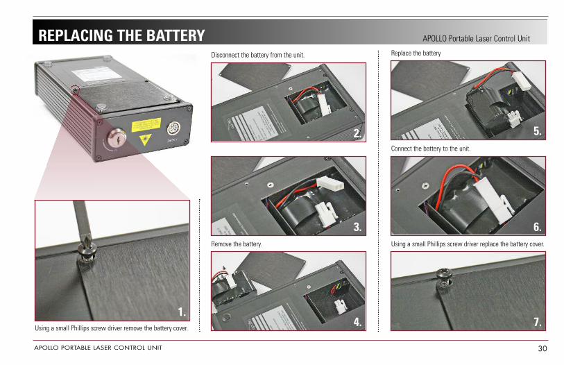
APOLLO Portable Laser Control UnitREPLACING THE BATTERYReplace the battery
Connect the battery to the unit.
Using a small Phillips screw driver replace the battery cover.
Disconnect the battery from the unit.
Remove the battery.
1.
2.
3.
5.
6.
7.4.Using a small Phillips screw driver remove the battery cover.

APOLLO PORTABLE LASER CONTROL UNIT 31
APOLLO Portable Laser Control Unit
© All rights reserved. No part of this manual may be reproduced, saved in a researchcenter or transferred by any means including electronic, mechanical, photographic or other records without previous approval from Pivotal Health Solutions, Inc. (APOLLO).
APOLLO operates a policy of continuous development. Therefore, it reserves the right to make changes and improvements to the Product described in this manual without prior notice.
The contents of this document are provided "as is ". Except as required by applicable law, no warranties of any kind, either expressed or implied, are made in relation to theaccuracy, reliability or contents of this document. APOLLO reserves the right to revise this document or withdraw it at any time without prior notice.
Neither APOLLO, its officers, employees or agents, nor the author of this manual, hold that the application of Laser Therapy will achieve any or all of the benefits referred to or implied in this text or in any other materials prepared by APOLLO. There may be other dangers or consequences associated with the use of Laser Therapy which are not referredto in this text.
While APOLLO has taken all possible care in the design and manufacture of this device, no responsibility can be taken by APOLLO for the way in which it is used. The purchaseroperates the APOLLO Laser Device at their own risk.
APOLLO will not accept any liability for any injury or damages resulting directly or indirectly from the use of the APOLLO device, any associated equipment or the informationcontained in this manual or any other materials or advice provided by APOLLO to the purchaser or any officer, employee, or agent of the purchaser.

0473