a limitations
TRANSCRIPT

8/8/2019 A Limitations
http://slidepdf.com/reader/full/a-limitations 1/7
The information provided in this document is to be used during simulated flight onlyand is not intended to be used in real life. Attention VA's - you may post this file on your site fordownload. Please do not post this information as a web page on your site. To all others: Thisinformation is provided for your personal use only . Distribution of this information in any formis not permitted without my approval. Distribution of this information in any payware product, CDor otherwise is not permitted.
Compiled by Matt Zagoren
Airbus A320-232 Limitations (IAE V2527-A5)
8/8/2019 A Limitations
http://slidepdf.com/reader/full/a-limitations 2/7
2
SELECTED LIMITATIONS All references to airspeed or Mach number relate to Indicated Airspeed or Indicated Mach Number,unless otherwise noted. All references to altitude relate to Pressure Altitude, unless otherwisenoted.
AVIONICS
AutolandAutoland is permitted using full flaps only.
Autoland - Maximum WindsHeadwind - 25 ktsTailwind - 10 ktsCrosswind other than CAT II/III - 15 ktsCrosswind CAT II/III (AFM) - 10 kts
Autopilot Engaged - Minimum AltitudeAfter Takeoff/Go-Around - 30' AGL
Enroute - 500' AGLNon-Precision Approaches - 50' Below MDACoupled Approaches - 50' AGLAutoland (One or Two Autopilots) - Touchdown
ILS Approaches (AFM)Do not arm the ILS APPR mode above 8200' AGL.
Inertial Reference SystemIn the NAV mode the IRU will not provide valid magnetic heading above 73° North and below 60°South. Flights above/below these latitudes are not permitted.
ENGINES (IAE V2527-A5)
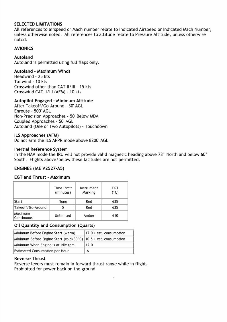
EGT and Thrust - Maximum
Time Limit(minutes)
InstrumentMarking
EGT(°C)
Start None Red 635
Takeoff/Go-Around 5 Red 635
MaximumContinuous
Unlimited Amber 610
Oil Quantity and Consumption (Quarts)
Minimum Before Engine Start (warm) 17.0 + est. consumption
Minimum Before Engine Start (cold/30°C) 10.5 + est. consumption
Minimum When Engine is at Idle rpm 12.0
Estimated Consumption per Hour .6
Reverse ThrustReverse levers must remain in forward thrust range while in flight.Prohibited for power back on the ground.
8/8/2019 A Limitations
http://slidepdf.com/reader/full/a-limitations 3/7
3
RPM - MaximumN1 - 100%N2 - 100%
FUEL
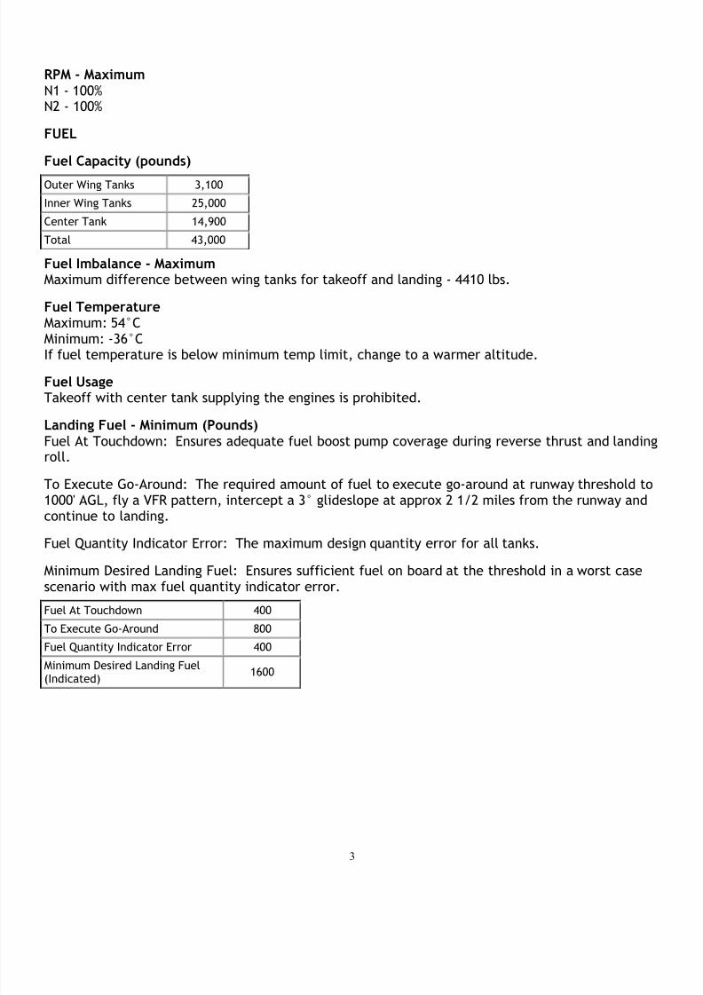
Fuel Capacity (pounds)
Outer Wing Tanks 3,100
Inner Wing Tanks 25,000
Center Tank 14,900
Total 43,000
Fuel Imbalance - MaximumMaximum difference between wing tanks for takeoff and landing - 4410 lbs.
Fuel TemperatureMaximum: 54°CMinimum: -36°CIf fuel temperature is below minimum temp limit, change to a warmer altitude.
Fuel UsageTakeoff with center tank supplying the engines is prohibited.
Landing Fuel - Minimum (Pounds)Fuel At Touchdown: Ensures adequate fuel boost pump coverage during reverse thrust and landingroll.
To Execute Go-Around: The required amount of fuel to execute go-around at runway threshold to1000' AGL, fly a VFR pattern, intercept a 3° glideslope at approx 2 1/2 miles from the runway and
continue to landing. Fuel Quantity Indicator Error: The maximum design quantity error for all tanks.
Minimum Desired Landing Fuel: Ensures sufficient fuel on board at the threshold in a worst casescenario with max fuel quantity indicator error.
Fuel At Touchdown 400
To Execute Go-Around 800
Fuel Quantity Indicator Error 400
Minimum Desired Landing Fuel(Indicated)
1600

8/8/2019 A Limitations
http://slidepdf.com/reader/full/a-limitations 4/7
4
Operating Fuel Values (Pounds)
Taxi Fuel Per Minute (not included in takeoff weight) 25
Minimum for Dispatch (not including taxi fuel) 6800
Minimum Hold for Contingencies (AFM Limit) 1000
Minimum Alternate Fuel 1200
Holding Fuel Per Hour 5000
APU Fuel Per Hour 290
HYDRAULICS
Brake TemperatureMaximum Brake Temperature for Takeoff - 300°C
Flaps/Slats Extended AltitudeMaximum - 20,000 MSL
Speed Brakes (AFM)
IMC Do not use from FAF inbound.
VMC Do not use below 1000' AGL.
Inflight With Flaps Retracted Do not use below 200 KIAS.
ICE AND RAIN
Engine Anti-Ice
• Engine anti-ice must be ON during all ground and flight operations when icing conditionsexist or are anticipated, except during climb and cruise when temperature is below -40°C
SAT.
• Engine anti-ice must be ON prior to and during descent in icing conditions, includingtemperatures below -40°C SAT.
Wing Anti-Ice
• Wing anti-ice is not permitted on the ground (AFM), or in flight when TAT exceeds 10°C.
• Use of APU bleed air for wing anti-ice is not permitted.
SPEEDS
Cockpit Window Open SpeedMaximum - 200 KIAS

8/8/2019 A Limitations
http://slidepdf.com/reader/full/a-limitations 5/7
5
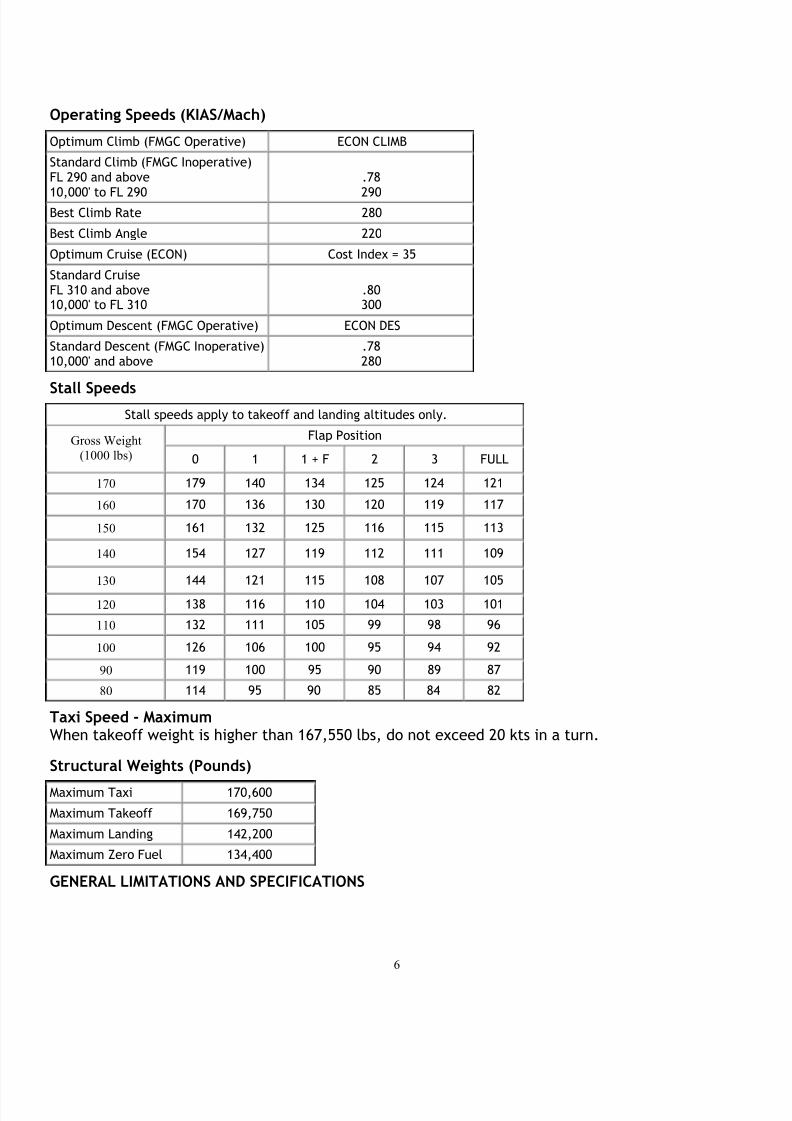
Design Maneuvering Speeds - Va (KIAS/Mach)
* Only when in alternate or direct flight control laws.
Pressure Altitude (1000 Feet)Speed
SL 10.0 16.0 20.0 24.0 28.0 30.0 39.0
* Va 248 250 260 270 280 290 295 .78
Flaps/Slat Extended Speeds - Vfe (KIAS)
Config 1 1 + F 2 3 FULL
Vfe 230 215 200 185 177
Slats 18 18 22 22 27
Flaps 0 10 15 20 40
RemarksInitial
ApproachTakeoff
Takeoff/Approach
Takeoff/ApproachLanding
Landing
Takeoff with Flaps 1 When Flaps 1 is selected for takeoff (1 + F), the flaps automatically retract to 0 at 210 KIAS.Takeoff or Go-Around with Flaps 2 or 3When Flaps 1 is selected, the 1+F configuration is obtained if airspeed is less than 210 KIAS. Theflaps automatically retract to configuration 0 at 210 KIAS.Flaps Selection in FlightWhen the flaps lever is moved from 0 to 1 in flight, only the slats are extended.
Landing Gear Limit Speeds - Vlo/Vle (KIAS/MACH) Retraction - Vlo 220
Extension - Vlo 250
Extended - Vle 280 / .67
Maximum Tire Speed 195 Knots Groundspeed
Maximum Operating Limit Speeds - Vmo/Mmo
Pressure AltitudeSpeed
SL - 25,000 25,000 - 39000
Vmo/Mmo 350 .82
Minimum Control Speed Air - VmcaVmca - 119 KIAS
Minimum Control Speed Ground - VmcgVmcg - 114 KIAS
8/8/2019 A Limitations
http://slidepdf.com/reader/full/a-limitations 6/7

8/8/2019 A Limitations
http://slidepdf.com/reader/full/a-limitations 7/7
7
Center of Gravity LimitsThe A320 has two certified CG envelopes. One is a curtailed (normal) envelope with a forwardlimit of 25%. The other is a full envelope with a forward limit of 15%. Most airplane combinationsof fuel and passenger loading will operate in the curtailed envelope. When load planning identifiesan aircraft as having a forward CG use the Forward Center of Gravity procedure in the takeoff section.
Flight Load Acceleration Limits (G Load)
Clean Configuration -1.0 to +2.5
Flaps Retracted and Slats Extended -1.0 to +2.5
Flaps and Slats Extended 0.0 to +2.0
Pressure Altitude - MaximumTakeoff and Landing - 8000'Operating Altitude - 39,100'
Runway SlopeMaximum - +/- 2%
Winds - Maximum (Knots)
The following are the maximum demonstratedcrosswinds with flight controls in normal anddirect law (with or without the yaw damper).
Crosswind -Takeoff 29
Crosswind -Landing 33
Crosswind with Gusts 38
Tailwind - Takeoff and Landing 10