a hybrid fuzzy/lqr based oscillation damping controller ...ijcee.org/papers/312-e321.pdf · in this...
TRANSCRIPT
International Journal of Computer and Electrical Engineering, Vol. 3, No. 2, April, 2011
1793-8163
184
Abstract—Analysis and damping of torsional oscillations in
series compensated transmission system is presented in this paper. Series compensation of transmission lines connected to turbo generators can result in Sub Synchronous Resonance (SSR) leading to adverse torsional oscillations. The use of Flexible AC Transmission System (FACTS) controllers such as Static Synchronous Compensator (STATCOM) are increasing in the network for enhancing power transfer capability, dynamic voltage support and also damping of power oscillations. In this paper, a hybrid Fuzzy/LQR (Linear Quadratic Regulator) control method for 3-level STATCOM control is introduced and applied for damping oscillations caused by SSR. Linear quadratic regulator (LQR) is an optimal control method that minimizes the cost function in order to achieve the optimal tradeoff between the use of control effort, the magnitude and the speed of response. Also it guarantees a stable control system. The Fuzzy logic is used to design of control system in outer loops of controller and designed supplementary controller for damping oscillation in STATCOM. The simulation results demonstrate the effectiveness of the proposed hybrid controller and its robustness performance. The operating range of the proposed control scheme was demonstrated as better that of the conventional controller.
Index Terms—STATCOM, Oscillation Damping, Fuzzy Controller, LQR Controller, Sub Synchronous Resonance.
I. INTRODUCTION Fixed series capacitors have long been used in power
systems as a cost-effective option for enhancing power transfer capability of HV transmission systems. However, the series capacitor has caused shaft damage in multistage steam turbine system in couple of occasions through subsynchronous resonance (SSR). SSR is an electric power system condition where the electric network exchanges energy with a turbine generator at one or more of the natural frequencies of the combined system under the subsynchronous frequency of the system [1]. This leads to turbine-generator shaft failure and system instability.
Rotor oscillations of generator at a torsion mode frequency, (fm) induce armature voltage components at frequencies (fern) given by:
moern fff ±= (1)When the subsynchronous component fern is close to
electrical resonant frequency, the subsynchronous torques produced by subsynchronous voltage components can be
Manuscript received June 8, 2010. Ali Ajami is with the electrical engineering department of Azarbaijan
university of Tarbiat Moallem, Tabriz, Iran, phone: +98-914-3183362; fax: +98-412-4327548; e-mail: [email protected]
Naser Taheri is with the electrical engineering department of, Islamic Azad University, Quchan Branch, Iran, e-mail: [email protected]
sustained. This interplay between electrical and mechanical systems is termed as torsional oscillations [2].
Flexible AC Transmission Systems (FACTS) technology is an important tool for permitting existing transmission facilities to be loaded, at least under contingency situations, up to their thermal limits without degrading system security [3-6]. The most striking feature is the ability to directly control transmission line flows by structurally changing parameters of the grid and to implement high-gain type controllers, based on fast switching.
The uses of FACTS devices like STATCOM are increasing in the network for enhancing power transfer, voltage stability and damping of power oscillations. As a promising technology, the control of STATCOM has been discussed in many literatures [7-10]. In this paper, the damping of torsional oscillations using STATCOM, connected at the middle bus is studied. A supplementary fuzzy control signal is added to control circuit to damping oscillations caused by series compensator capacitance. To improve STATCOM controller, hybrid Fuzzy/LQR controller is proposed.
II. DYNAMIC MODELLING OF STATCOM The system considered is an IEEE benchmark used to
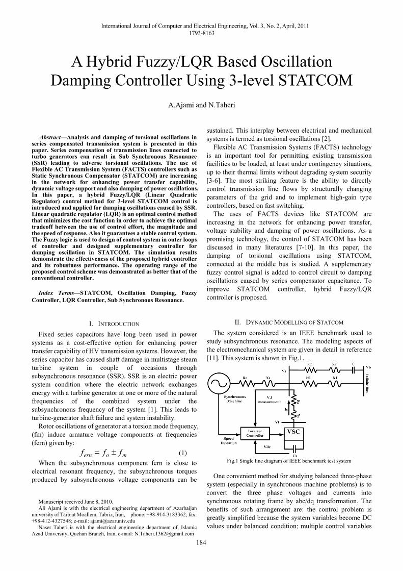
study subsynchronous resonance. The modeling aspects of the electromechanical system are given in detail in reference [11]. This system is shown in Fig.1.
Fig.1 Single line diagram of IEEE benchmark test system
One convenient method for studying balanced three-phase system (especially in synchronous machine problems) is to convert the three phase voltages and currents into synchronous rotating frame by abc/dq transformation. The benefits of such arrangement are: the control problem is greatly simplified because the system variables become DC values under balanced condition; multiple control variables
A Hybrid Fuzzy/LQR Based Oscillation Damping Controller Using 3-level STATCOM
A.Ajami and N.Taheri
International Journal of Computer and Electrical Engineering, Vol. 3, No. 2, April, 2011
1793-8163
185
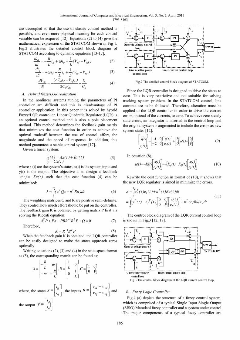
are decoupled so that the use of classic control method is possible, and even more physical meaning for each control variable can be acquired [12]. Equations (2) to (4) give the mathematical expression of the STATCOM shown in Fig 1. Fig.2 illustrates the detailed control block diagram of STATCOM according to dynamic equations [13-17].
)VV(L
iiLR
dtdi
sdtdqdd −++−= 1ω (2)
)VV(L
iLRi
dtdi
sqtqqdq −+−−= 1ω (3)
s
L
dcs
qtqdtddc
Ci
VC)iViV(
dtdV −
+−=
23
(4)
A. Hybrid fuzzy/LQR realization In the nonlinear systems tuning the parameters of PI
controller are difficult and this is disadvantage of PI controller application. In this paper it is solved by hybrid Fuzzy/LQR controller. Linear Quadratic Regulator (LQR) is an optimal control method and is also a pole placement method. This method determines the feedback gain matrix that minimizes the cost function in order to achieve the optimal tradeoff between the use of control effort, the magnitude and the speed of response. In addition, this method guarantees a stable control system [17].
Given a linear system:
)t(Cxy)t(Bu)t(Ax)t(x
.
=+= (5)
where x (t) are the system’s states, u(t) is the system input and y(t) is the output. The objective is to design a feedback
)t(Kx)t(u −= such that the cost function (4) can be minimized:
∫∞
+=0
dt)RuuQxx(J TT (6)
The weighting matrices Q and R are positive semi-definite. They control how much effort should be put on the controller. The feedback gain K is obtained by getting matrix P first via solving the Riccati equation:
01 =+−+ − QPBPBRPAPA TT (7)Therefore,
PBRK T1−= (8)When the feedback gain K is obtained, the LQR controller
can be easily designed to make the states approach zeros optimally.
Writing equations (2), (3) and (4) in the state space format as (5), the corresponding matrix can be found as:
⎥⎦⎤
⎢⎣⎡=
⎥⎥⎥
⎦
⎤
⎢⎢⎢
⎣
⎡
=⎥⎥⎥
⎦
⎤
⎢⎢⎢
⎣
⎡
−−
−= 10
0110
01
C,
L
LB,
LR
LR
Aω
ω
where, the states ⎥⎦
⎤⎢⎣
⎡=q
dii
x , the inputs ⎥⎦
⎤⎢⎣
⎡−−
=sqtq
sdtdvvvv
u and
the output ⎥⎦
⎤⎢⎣
⎡=q
dii
y .
Fig.2 The detailed control block diagram of STATCOM.
Since the LQR controller is designed to drive the states to
zero. This is very restrictive and not suitable for solving tracking system problem. In the STATCOM control, line currents are to be followed. Therefore, alteration must be applied to the LQR controller in order to drive the current errors, instead of the currents, to zero. To achieve zero steady state errors, an integrator is inserted in the control loop and the original system is augmented to include the errors as new system states [12].
rI)t(uB)t(e)t(x
CA
)t(e
)t(xI
.
I
.
⎥⎦⎤
⎢⎣⎡+⎥⎦
⎤⎢⎣⎡+⎥⎦
⎤⎢⎣⎡⎥⎦⎤
⎢⎣⎡−=
⎥⎥
⎦
⎤
⎢⎢
⎣
⎡ 000
0 (9)
In equation (8),
[ ] ⎥⎦⎤
⎢⎣⎡−=⎥⎦
⎤⎢⎣⎡−= )t(e
)t(x)t(K)t(K)t(e)t(x)t(K)t(u
IIx
I (10)
Rewrite the cost function in format of (10), it shows that
the new LQR regulator is aimed in minimize the errors.
[ ] dt)t(Ru)t(u)t(e)t(x
I)t(e)t(x
dt)t(Ru)t(u)t(e)t(eJ
Tt
I
TI
T
tT
ITI
+⎥⎦⎤
⎢⎣⎡⎥⎦⎤
⎢⎣⎡=
+=
∫
∫
0
0
000
(11)
The control block diagram of the LQR current control loop
is shown in Fig.3 [12, 17].
Fig.3 The control block diagram of the LQR current control loop.
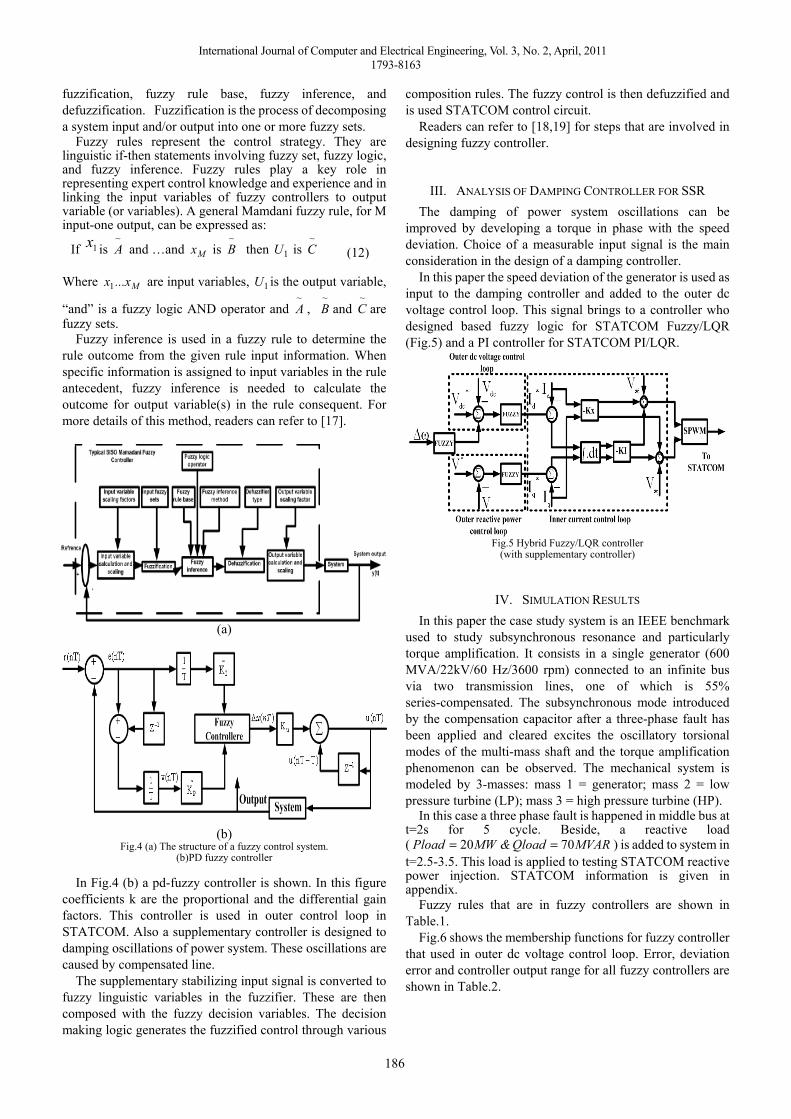
B. Fuzzy Logic Controller Fig.4 (a) depicts the structure of a fuzzy control system,
which is comprised of a typical Single Input Single Output (SISO) Mamdani fuzzy controller and a system under control. The major components of a typical fuzzy controller are
International Journal of Computer and Electrical Engineering, Vol. 3, No. 2, April, 2011
1793-8163
186
fuzzification, fuzzy rule base, fuzzy inference, and defuzzification. Fuzzification is the process of decomposing a system input and/or output into one or more fuzzy sets.
Fuzzy rules represent the control strategy. They are linguistic if-then statements involving fuzzy set, fuzzy logic, and fuzzy inference. Fuzzy rules play a key role in representing expert control knowledge and experience and in linking the input variables of fuzzy controllers to output variable (or variables). A general Mamdani fuzzy rule, for M input-one output, can be expressed as:
If 1x is ~A and …and Mx is
~B then 1U is
~C (12)
Where Mx...x1 are input variables, 1U is the output variable,
“and” is a fuzzy logic AND operator and ~A ,
~B and
~C are
fuzzy sets. Fuzzy inference is used in a fuzzy rule to determine the
rule outcome from the given rule input information. When specific information is assigned to input variables in the rule antecedent, fuzzy inference is needed to calculate the outcome for output variable(s) in the rule consequent. For more details of this method, readers can refer to [17].
(a)
(b) Fig.4 (a) The structure of a fuzzy control system.
(b)PD fuzzy controller
In Fig.4 (b) a pd-fuzzy controller is shown. In this figure coefficients k are the proportional and the differential gain factors. This controller is used in outer control loop in STATCOM. Also a supplementary controller is designed to damping oscillations of power system. These oscillations are caused by compensated line.
The supplementary stabilizing input signal is converted to fuzzy linguistic variables in the fuzzifier. These are then composed with the fuzzy decision variables. The decision making logic generates the fuzzified control through various
composition rules. The fuzzy control is then defuzzified and is used STATCOM control circuit.
Readers can refer to [18,19] for steps that are involved in designing fuzzy controller.
III. ANALYSIS OF DAMPING CONTROLLER FOR SSR The damping of power system oscillations can be
improved by developing a torque in phase with the speed deviation. Choice of a measurable input signal is the main consideration in the design of a damping controller.
In this paper the speed deviation of the generator is used as input to the damping controller and added to the outer dc voltage control loop. This signal brings to a controller who designed based fuzzy logic for STATCOM Fuzzy/LQR (Fig.5) and a PI controller for STATCOM PI/LQR.
Fig.5 Hybrid Fuzzy/LQR controller (with supplementary controller)
IV. SIMULATION RESULTS In this paper the case study system is an IEEE benchmark
used to study subsynchronous resonance and particularly torque amplification. It consists in a single generator (600 MVA/22kV/60 Hz/3600 rpm) connected to an infinite bus via two transmission lines, one of which is 55% series-compensated. The subsynchronous mode introduced by the compensation capacitor after a three-phase fault has been applied and cleared excites the oscillatory torsional modes of the multi-mass shaft and the torque amplification phenomenon can be observed. The mechanical system is modeled by 3-masses: mass 1 = generator; mass 2 = low pressure turbine (LP); mass 3 = high pressure turbine (HP).
In this case a three phase fault is happened in middle bus at t=2s for 5 cycle. Beside, a reactive load ( MVARQload&MWPload 7020 == ) is added to system in t=2.5-3.5. This load is applied to testing STATCOM reactive power injection. STATCOM information is given in appendix.
Fuzzy rules that are in fuzzy controllers are shown in Table.1.
Fig.6 shows the membership functions for fuzzy controller that used in outer dc voltage control loop. Error, deviation error and controller output range for all fuzzy controllers are shown in Table.2.
International Journal of Computer and Electrical Engineering, Vol. 3, No. 2, April, 2011
1793-8163
187
TABLE I FUZZY CONTROLLER’S RULES
eΔ e
PB PS ZE NS NB
PB PB PB PS PS ZEPS PB PS PS ZE NSZE PS PS ZE NS NSNS PS ZE N
S NS NB
NB ZE NS
NS
NB NB
TABLE.II FUZZY CONTROLLER’S INFORMATION Fuzzy controllers Range
Error Error Deviation OutputOuter dc voltage control loop [-1,1] [-0.001,0.001] [-20,20]
Outer reactive power control loop
[-1,1] [-1,1] [-10,10]
Supplementary damping controller
[-0.1,-0.1] [-0.001,0.001] [-1,1]
(a) (b)
Fig.6 Membership functions for outer dc voltage control loop (a) Error (b)Deviation of Error
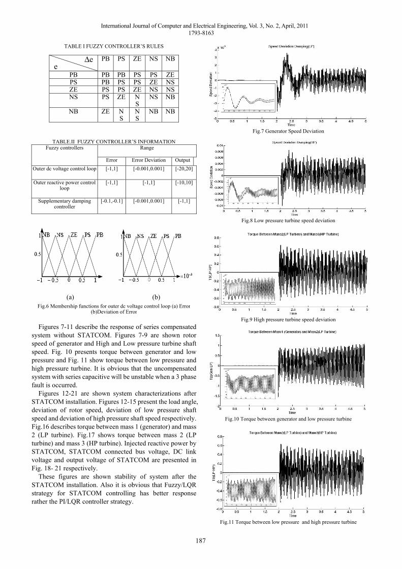
Figures 7-11 describe the response of series compensated
system without STATCOM. Figures 7-9 are shown rotor speed of generator and High and Low pressure turbine shaft speed. Fig. 10 presents torque between generator and low pressure and Fig. 11 show torque between low pressure and high pressure turbine. It is obvious that the uncompensated system with series capacitive will be unstable when a 3 phase fault is occurred.
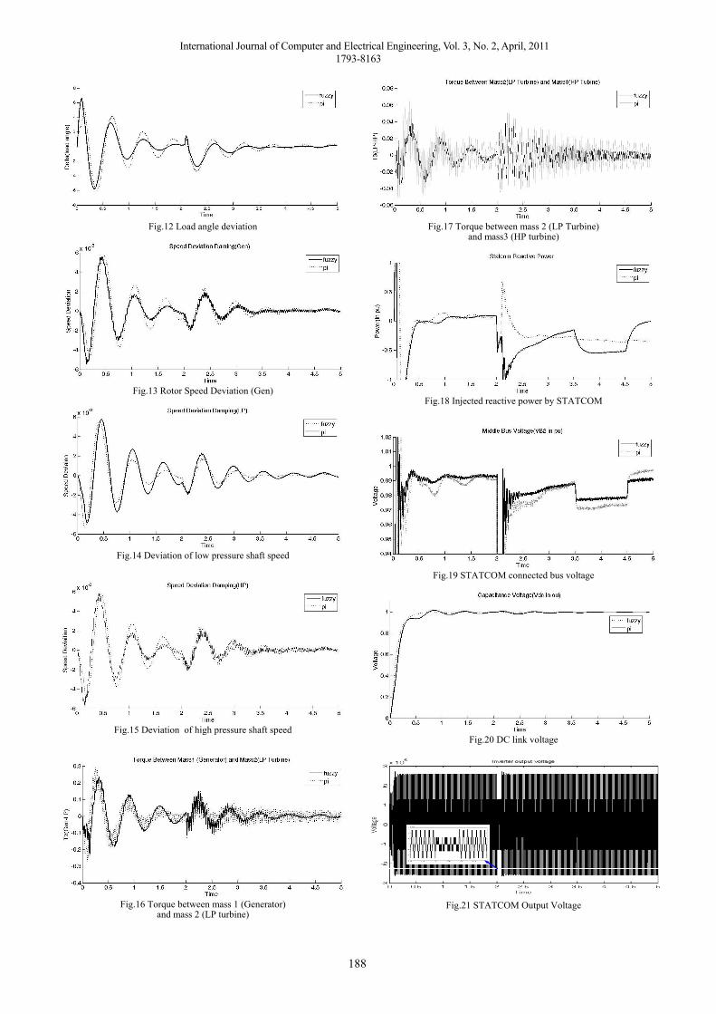
Figures 12-21 are shown system characterizations after STATCOM installation. Figures 12-15 present the load angle, deviation of rotor speed, deviation of low pressure shaft speed and deviation of high pressure shaft speed respectively. Fig.16 describes torque between mass 1 (generator) and mass 2 (LP turbine). Fig.17 shows torque between mass 2 (LP turbine) and mass 3 (HP turbine). Injected reactive power by STATCOM, STATCOM connected bus voltage, DC link voltage and output voltage of STATCOM are presented in Fig. 18- 21 respectively.
These figures are shown stability of system after the STATCOM installation. Also it is obvious that Fuzzy/LQR strategy for STATCOM controlling has better response rather the PI/LQR controller strategy.
Fig.7 Generator Speed Deviation
Fig.8 Low pressure turbine speed deviation
Fig.9 High pressure turbine speed deviation
Fig.10 Torque between generator and low pressure turbine
Fig.11 Torque between low pressure and high pressure turbine
International Journal of Computer and Electrical Engineering, Vol. 3, No. 2, April, 2011
1793-8163
188
Fig.12 Load angle deviation
Fig.13 Rotor Speed Deviation (Gen)
Fig.14 Deviation of low pressure shaft speed
Fig.15 Deviation of high pressure shaft speed
Fig.16 Torque between mass 1 (Generator) and mass 2 (LP turbine)
Fig.17 Torque between mass 2 (LP Turbine)and mass3 (HP turbine)
Fig.18 Injected reactive power by STATCOM
Fig.19 STATCOM connected bus voltage
Fig.20 DC link voltage
Fig.21 STATCOM Output Voltage
International Journal of Computer and Electrical Engineering, Vol. 3, No. 2, April, 2011
1793-8163
189
V. CONCLUSION In this paper a 3-level STATCOM is used to damping
oscillation caused by series capacitor compensator. Two different strategies for STATCOM controlling presented. The presented simulation results show that STATCOM is capable to power system oscillation damping and the hybrid Fuzzy/LQR strategy acts well than the conventional PI/LQR method. The simulation results support the applications of hybrid Fuzzy/LQR controllers in power systems.
APPENDIX STATCOM information:
FCdc μ2500= , FC&mHL filterfilter μ203 == , Ω== 55048 .R&mHL transtrans
PI controllers’ coefficients: DC loop: 15178 .K,.K IP == AC loop: 850550 .K,.K IP == Supplementary controller: 5110 .K,K Ip == LQR information:
⎥⎦⎤
⎢⎣⎡
−−−=
⎥⎦⎤
⎢⎣⎡=
078201005300100782000530
01000010
....K
,..R
REFERENCES [1] IEEE SSR Working Group, “Proposed terms and definitions for
Subsynchronous Resonance,” IEEE Symposium on Colmtermeasures for Subsynchronous Resonance, vol. SITHM, 86-9-PWR, pp. 92-97, 1981.
[2] K.R.Padiyar, Analysis of Subsynchronous Resonance in Power Systems, Kluwer Academic Publishers, 1999.
[3] Song, Y. H. and Johns, A. T., Flexible AC transmission systems (FACTS),London, Institution of Electrical Engineers, 1999.
[4] Hingorani, N. G. and Gyugyi, L., Understanding FACTS: concepts and [5] technology of flexible AC transmission systems, New York, IEEE
Press, 2000. [6] Acha, E., FACTS: modelling and simulation in power networks,
Chichester,Wiley, 2004. [7] G. G. Pablo, G. C. Aurelio, Control System for a PWM-based
STATCOM, IEEE Transactions on Power Delivery, vol. 15, Issue 4, Oct.2000.
[8] V. Blasko, V. Kaura, A New Mathematical Model and Control of a Three-Phase AC-DC Voltage Source Converter, IEEE Transactions on Power Electronics, vol. 12, no. 1, Jan 1997.
[9] P. W. Lehn, M. R. Iravani, Experimental Evaluation of STATCOM Closed Loop, IEEE Transactions on Power Delivery, vol. 13, No. 4, Oct. 1998.
[10] P. Rao, M. L. Crow, Z. Yang, “STATCOM Control for Power System Voltage Control Applications, IEEE Transactions on Power Delivery, vol. 15, no. 4, Oct. 2000.
[11] Mathur, R. M. and Varma, R. K., Thyristor-based FACTS controllers for electrical transmission systems, Piscataway, NJ, IEEE, 2002.
[12] IEEE Subsynchronous Resonance working group, Second benchmark model for computer simulation of subsynchronous resonance, IEEE Transactions on Power Apparatus and Systems, vol. PAS-104, no. 5, 1985, pp. 1057-1066.
[13] W.Ren, L.Qian, D.Cartes, M.Steurer , A Multivariable Control Method in STATCOM Application for Performance Improvemen, industry applications conference, pp.2246-2250,vol.3, oct 2005.
[14] G.G.Pablo, G.C.Aurelio, Control System for a PWM-based STATCOM, IEEE Transactions on Power Delivery, vol. 15, Issue 4, Oct. 2000.
[15] V.Blasko, V.Kaura, A New Mathematical Model and Control of a Three-Phase AC-DC Voltage Source Converter, IEEE Transactions on Power Electronics, vol. 12, no. 1, Jan 1997.
[16] J.B.Burl, Linear Optimal Control: H2 and H∞ Methods, 1999 Addison Wesley Longman, Inc. pp. 303-310
[17] H.Ying, Fuzzy Control and Modeling: Analytical Foundations and Applications, IEEE Press Series on Biomedical Engineering, Series Editor: Metin Akay, New York, 2000.
[18] H.A.Toliat, J. Sadeh and R. Ghazi, Design of augmented fuzzy logic power system stabilizers to enhance power system stability, IEEE Trans. Energy Conversion, vol. 11, no.1, pp.97-103, 1996.
[19] T.J. Ross, Fuzzy Logic with Engineering Applications, McGraw Hill, New York, 1995.
Ali Ajami received his B.Sc. and M. Sc. degrees from the Electrical and Computer Engineering Faculty of Tabriz University, Iran, in Electronic Engineering and Power Engineering in 1996 and 1999, respectively, and his Ph.D. degree in 2005 from the Electrical and Computer Engineering Faculty of Tabriz University, Iran, in Power Engineering. His main research interests are dynamic and steady state modeling and analysis of FACTS devices, harmonics and power quality compensation systems, microprocessors, DSP and computer based control systems.
Naser Taheri received the B.Sc. in university of Guilan Rasht(Iran) in Electronic Engineering on 2007 and M.Sc degree from Azarbaijan University of Tarbiat Moallem, Tabriz (Iran) in Power Electrical Engineering on 2009. He is currently researching on Power System Control, Flexible AC Transmission Systems (FACTS) and power systems dynamic modeling.