a high performance messaging system for peer-to …cpress/ref/2003-java-messaging...a high...
TRANSCRIPT

A HIGH PERFORMANCE MESSAGING SYSTEM FOR
PEER-TO-PEER NETWORKS
A THESIS IN Computer Science
Presented to the Faculty of the University of Missouri - Kansas City in partial fulfillment of
the requirements for the degree
MASTER OF COMPUTER SCIENCE
by MARKUS OLIVER JUNGINGER
Kansas City, Missouri 2003

© 2003
MARKUS OLIVER JUNGINGER
ALL RIGHTS RESERVED
ii
A HIGH PERFORMANCE MESSAGING SYSTEM FOR
PEER-TO-PEER NETWORKS
Markus Junginger, candidate for the Master of Science degree
University of Missouri-Kansas City, 2003
ABSTRACT
Emerging peer-to-peer concepts provide new possibilities but also challenges for
distributed applications. Despite their significant potential, current peer-to-peer networks lack
efficient group communication. This thesis addresses this deficiency and proposes the P2P
Messaging System, which collaborates with peer-to-peer networks. For each peer group, it
establishes virtual overlay networks based on the novel multi-ring topology that addresses peer
heterogeneity and dynamics. Thus, the system overcomes the topological restrictions of peer-
to-peer networks and provides a scalable and robust high performance infrastructure tailored
to group communication. The P2P Messaging System derived from a server-less and
extensible high performance messaging system, also introduced by this thesis. Because of the
component-based architecture, many components of the server-less system are reused by the
peer-to-peer system. Experimental benchmarks provided evidence for the high performance

iii
and scalability of the P2P Messaging System. This thesis’ contribution is a high performance
messaging framework that improves group communication in peer-to-peer environments.
This abstract of 150 words is approved as to form and content.
Yugyung Lee, Ph.D. Assistant Professor
School of Interdisciplinary Computing and Engineering

iv
The undersigned, appointed by the Dean of the School of Interdisciplinary Computing
and Engineering, have examined a thesis titled “A High Performance Messaging System for
Peer-to-Peer Networks,” presented by Markus Oliver Junginger, candidate for the Master of
Science degree, and hereby certify that in their opinion it is worthy of acceptance.
Yugyung Lee, Ph.D. Date Assistant Professor Software Architecture Discipline
E.K. Park, Ph.D. Date Professor Software Architecture Discipline Yijie Han, Ph.D. Date Associate Professor Software Architecture Discipline

v
CONTENTS
ABSTRACT.. . . . . . . . . . . . . . . . . . . . . . . . . . . . . . . . . . . . . . . . . . . . . . . . . . . . . . . . . . . . . . . . . . . . . . . . . . . . . . . . . . . . . . . . . . . . . . . . . . . . . . ii
ILLUSTRATION... . . . . . . . . . . . . . . . . . . . . . . . . . . . . . . . . . . . . . . . . . . . . . . . . . . . . . . . . . . . . . . . . . . . . . . . . . . . . . . . . . . . . . . . . . . . . .v
TABLES.. . . . . . . . . . . . . . . . . . . . . . . . . . . . . . . . . . . . . . . . . . . . . . . . . . . .. . . . . . . . . . . . . . . . . . . . . . . . . . . . . . . . . . . . . . . . . . . . . . . . . . . . . . x
Chapter
1. INTRODUCTION... . . . . . . . . . . . . . . . . . . . . . . . . . . . . . . . . . . . . . . . . . . . . . . . . . . . . . . . . . . . . . . . . . . . . . . . . . . . . . . . . . . . . . 1
2. RELATED WORK... . . . . . . . . . . . . . . . . . . . . . . . . . . . . . . . . . . . . . . . . . . . . . . . . . . . . . . . . . . . . . . . . . . . . . . . . . . . . . . . . . . . . . 5
3. A SERVER-LESS MESSAGING SYSTEM... . . . . . . . . . . . . . . . . . . . . . . . . . . . . . . . . . . . . . . . . . . . . . . . . . . . . . 31
4. NETWORK ARCHITECTURES.. . . . . . . . . . . . . . . . . . . . . . . . . . . . . . . . . . . . . . . . . . . . . . . . . . . . . . . . . . . . . . . . . . . 51
5. THE P2P MESSAGING SYSTEM AND THE MULTI-RING TOPOLOGY... . . . . . . . . 63
6. EVALUATION.. . . . . . . . . . . . . . . . . . . . . . . . . . . . . . . . . . . . . . . . . . . . . . . . . . . . . . . . . . . . . . . . . . . . . . . . . . . . . . . . . . . . . . . . . . 92
7. CONCLUSION.. . . . . . . . . . . . . . . . . . . . . . . . . . . . . . . . . . . . . . . . . . . . . . . . . . . . . . . . . . . . . . . . . . . . . . . . . . . . . . . . . . . . . . . . . 118
REFERENCES.. . . . . . . . . . . . . . . . . . . . . . . . . . . . . . . . . . . . . . . . . . . . . . . . . . . . . . . . . . . . . . . . . . . . . . . . . . . . . . . . . . . . . . . . . . . . . . 120
VITA.. . . . . . . . . . . . . . . . . . . . . . . . . . . . . . . . . . . . . . . . . . . . . . . . . . . . . .. . . . . . . . . . . . . . . . . . . . . . . . . . . . . . . . . . . . . . . . . . . . . . . . . . . . . 124

vi
ILLUSTRATIONS
Figure Page
1. COM+ Events Architecture. . . . . . . . . . . . . . . . . . . . . . . .….. . . . . . . . . . . . . . . . . . . . . . . . . . . . . . . . . . . . . . . . . . . . . . 10
2. Basic Model of the CORBA Event Service. . . . . . . . . . . . . . . . . . . . . . . . . . . . . . . . . . . . . .….. . . . . . . . . . . . . 12
3. Architecture of the CORBA Event Service. . . . . . . . . . . . . . . . . . . . . . . . . . . . . . . . . . . . . . . . . . . . . . . . . . . . . . . . 14
4. JMS Publisher/Subscriber Architecture . . . . . . . . . . . . . . . . . . . . . . . . . . . . . . . . . . . . . . . . . . . . . . . . . . . . . . . . . . . 18
5. Extended Publisher/Subscriber Model . . . . . . . . . . . . . . . . . . . . . . . . . . . . . . . . . . . . . . . . . . . . . . . . . . . . . . . . . . . . 32
6. Feedback Topic Conceptual Model . . . . . . . . . . . . . . . . . . . . . . . . . . . . . . . . . . . . . . . . . . . . . . . . . . . . . . . . . . . . . . . . . 33
7. ReturnChannel Conceptual Model . . . . . . . . . . . . . . . . . . . . . . . . . . . . . . . . . . . . . . . . . . . . . . . . . . . . . . . . . . . . . . . . . . 34
8. Connection Types and Wrappers. . . . . . . . . . . . . . . . . . . . . . . . . . . . . . . . . . . . . . . . . . . . . . . . . . . . . . . . . . . . . . . . . . . . 37
9. Connection Initialization Sequence. . . . . . . . . . . . . . . . . . . . . . . . . . . . . . . . . . . . . . . . . . . . . . . . . . . . . . . . . . . . . . . . . . 39
10. Link Initialization. . . . . . . . . . . . . . . . . . . . . . . . . . . . . . . . . . . . . . . . . . . . . . . . . . . . . . . . . . . . . . . . . . . . . . . . . . . . . . . . . . . . . . . . 42
11. Publishing Messages. . . . . . . . . . . . . . . . . . . . . . . . . . . . . . . . . . . . . . . . . . . . . . . . . . . . . . . . . . . . . . . . . . . . . . . . . . . . . . . . . . . . 44
12. Receiving Messages. . . . . . . . . . . . . . . . . . . . . . . . . . . . . . . . . . . . . . . . . . . . . . . . . . . . . . . . . . . . . . . . . . . . . . . . . . . . . . . . . . . . . 45
13. MessageEncoder/MessageDecoder Architecture. . . . . . . . . . . . . . . . . . . . . . . . . . . . . . . . . . . . . . . . . . . . . . . . 49
14. Publisher/Subscriber Topology. . . . . . . . . . . . . . . . . . . . . . . . . . . . . . . . . . . . . . . . . . . . . . . . . . . . . . . . . . . . . . . . . . . . . . 56
15. Message Server Topology. . . . . . . . . . . . . . . . . . . . . . . . . . . . . . . . . . . . . . . . . . . . . . . . . . . . . . . . . . . . . . . . . . . . . . . . . . . . . . 57
16. Message Router Topology. . . . . . . . . . . . . . . . . . . . . . . . . . . . . . . . . . . . . . . . . . . . . . . . . . . . . . . . . . . . . . . . . . . . . . . . . . . . . 58
17. Peer-to-Peer Topology. . . . . . . . . . . . . . . . . . . . . . . . . . . . . . . . . . . . . . . . . . . . . . . . . . . . . . . . . . . . . . . . . . . . . . . . . . . . . . . . . 60
18. Peer-to-Peer Cluster Topology. . . . . . . . . . . . . . . . . . . . . . . . . . . . . . . . . . . . . . . . . . . . . . . . . . . . . . . . . . . . . . . . . . . . . . . 61
19. Topic-subscribers in the Peer-to-Peer Network. . . . . . . . . . . . . . . . . . . . . . . . . . . . . . . . . . . . . . . . . . . . . . . . . . 65
vii
20. Topic Overlay Network. . . . . . . . . . . . . . . . . . . . . . . . . . . . . . . . . . . . . . . . . . . . . . . . . . . . . . . . . . . . . . . . . . . . . . . . . . . . . . . 66
21. Peer-to-Peer and Topic-Peers Layers. . . . . . . . . . . . . . . . . . . . . . . . . . . . . . . . . . . . . . . . . . . . . . . . . . . . . . . . . . . . . . . 67
22. Ring Topology. . . . . . . . . . . . . . . . . . . . . . . . . . . . . . . . . . . . . . . . . . . . . . . . . . . . . . . . . . . . . . . . . . . . . . . . . . . . . . . . . . . . . . . . . . . 67
23. Tree Topology: utilizes individual Peer Bandwidth Capabilities. . . . . . . . . . . . . . . . . . . . . . . . . . . . . . . 70
24. Outer and Inner Ring.. . . . . . . . . . . . . . . . . . . . . . . . . . . . . . . . . . . . . . . . . . . . . . . . . . . . . . . . . . . . . . . . . . . . . . . . . . . . . . . . . . 72
25. Ring. . . . . . . . . . . . . . . . . . . . . . . . . . . . . . . . . . . . . . . . . . . . . . . . . . . . . . . . . . . . . . . . . . . . . . . . . . . . . . . . . . . . . . . . . . . . . . . . . . . . . . . . 74
26. Ring with Backup Links. . . . . . . . . . . . . . . . . . . . . . . . . . . . . . . . . . . . . . . . . . . . . . . . . . . . . . . . . . . . . . . . . . . . . . . . . . . . . . . . 75
27. Nodes before Swapping. . . . . . . . . . . . . . . . . . . . . . . . . . . . . . . . . . . . . . . . . . . . . . . . . . . . . . . . . . . . . . . . . . . . . . . . . . . . . . . . 80
28. Temporary Situation during Swapping A.. . . . . . . . . . . . . . . . . . . . . . . . . . . . . . . . . . . . . . . . . . . . . . . . . . . . . . . . . 81
29. Temporary Situation during Swapping B. . . . . . . . . . . . . . . . . . . . . . . . . . . . . . . . . . . . . . . . . . . . . . . . . . . . . . . . . . . 81
30. Situation after Swapping.. . . . . . . . . . . . . . . . . . . . . . . . . . . . . . . . . . . . . . . . . . . . . . . . . . . . . . . . . . . . . . . . . . . . . . . . . . . . . . 81
31. A new Node is going to be added in the Ring. . . . . . . . . . . . . . . . . . . . . . . . . . . . . . . . . . . . . . . . . . . . . . . . . . . . 82
32. The new Node is integrated in the Ring.. . . . . . . . . . . . . . . . . . . . . . . . . . . . . . . . . . . . . . . . . . . . . . . . . . . . . . . . . . . 82
33. Situation before Disconnect. . . . . . . . . . . . . . . . . . . . . . . . . . . . . . . . . . . . . . . . . . . . . . . . . . . . . . . . . . . . . . . . . . . . . . . . . . 84
34. Ring with Activated Backup Link after Disconnect. . . . . . . . . . . . . . . . . . . . . . . . . . . . . . . . . . . . . . . . . . . . . . 84
35. Completely Restored Ring.. . . . . . . . . . . . . . . . . . . . . . . . . . . . . . . . . . . . . . . . . . . . . . . . . . . . . . . . . . . . . . . . . . . . . . . . . . . . 85
36. P2P Messaging System Prototype: System Model. . . . . . . . . . . . . . . . . . . . . . . . . . . . . . . . . . . . . . . . . . . . . . . . 87
37. P2P Messaging System Prototype: Helper, P2PJxta, and RingMessage. . . . . . . . . . . . . . . . . . . . . . 90
38. JXTA Message Rate: One Receiver. . . . . . . . . . . . . . . . . . . . . . . . . . . . . . . . . . . . . . . . . . . . . . . . . . . . . . . . . . . . . . . . . . 99
39. JXTA Message Rate: Three Receivers. . . . . . . . . . . . . . . . . . . . . . . . . . . . . . . . . . . . . . . . . . . . . . . . . . . . . . . . . . . . . . 99
40. JXTA Message Rate: Five Receivers. . . . . . . . . . . . . . . . . . . . . . . . . . . . . . . . . . . . . . . . . . . . . . . . . . . . . . . . . . . . . . . 100
41. JXTA Message Rate: Seven Receivers. . . . . . . . . . . . . . . . . . . . . . . . . . . . . . . . . . . . . . . . . . . . . . . . . . . . . . . . . . . . . 100
viii
42. JXTA Message Rate: Nine Receivers. . . . . . . . . . . . . . . . . . . . . . . . . . . . . . . . . . . . . . . . . . . . . . . . . . . . . . . . . . . . . . 101
43. JXTA Message Rate: Eleven Receivers. . . . . . . . . . . . . . . . . . . . . . . . . . . . . . . . . . . . . . . . . . . . . . . . . . . . . . . . . . . 101
44. JXTA: Relative Message Rate for the Sender. . . . . . . . . . . . . . . . . . . . . . . . . . . . . . . . . . . . . . . . . . . . . . . . . . . . 102
45. JXTA: Relative Message Rate for the Receiver. . . . . . . . . . . . . . . . . . . . . . . . . . . . . . . . . . . . . . . . . . . . . . . . . . 103
46. P2PMS Message Rate: One Receiver. . . . . . . . . . . . . . . . . . . . . . . . . . . . . . . . . . . . . . . . . . . . . . . . . . . . . . . . . . . . . . 105
47. P2PMS Message Rate: Three Receivers. . . . . . . . . . . . . . . . . . . . . . . . . . . . . . . . . . . . . . . . . . . . . . . . . . . . . . . . . . . 105
48. P2PMS Message Rate: Five Receivers. . . . . . . . . . . . . . . . . . . . . . . . . . . . . . . . . . . . . . . . . . . . . . . . . . . . . . . . . . . . . 106
49. P2PMS Message Rate: Seven Receivers. . . . . . . . . . . . . . . . . . . . . . . . . . . . . . . . . . . . . . . . . . . . . . . . . . . . . . . . . . . 106
50. P2PMS Message Rate: Nine Receivers. . . . . . . . . . . . . . . . . . . . . . . . . . . . . . . . . . . . . . . . . . . . . . . . . . . . . . . . . . . . 107
51. P2PMS Message Rate: Eleven Receivers. . . . . . . . . . . . . . . . . . . . . . . . . . . . . . . . . . . . . . . . . . . . . . . . . . . . . . . . . 107
52. P2PMS: Relative Message Rate for the Sender. . . . . . . . . . . . . . . . . . . . . . . . . . . . . . . . . . . . . . . . . . . . . . . . . . 108
53. P2PMS: Relative Message Rate for the Receiver. . . . . . . . . . . . . . . . . . . . . . . . . . . . . . . . . . . . . . . . . . . . . . . . 109
54. P2PMS’ and JXTA’s Data Rate: One Receiver. . . . . . . . . . . . . . . . . . . . . . . . . . . . . . . . . . . . . . . . . . . . . . . . . . 111
55. P2PMS’ and JXTA’s Data Rate: Three Receivers. . . . . . . . . . . . . . . . . . . . . . . . . . . . . . . . . . . . . . . . . . . . . . . 111
56. P2PMS’ and JXTA’s Data Rate: Eleven Receivers. . . . . . . . . . . . . . . . . . . . . . . . . . . . . . . . . . . . . . . . . . . . . 112
57. Message Rate Factors for Sending.. . . . . . . . . . . . . . . . . . . . . . . . . . . . . . . . . . . . . . . . . . . . . . . . . . . . . . . . . . . . . . . . 113
58. Message Rate Factors for Receiving. . . . . . . . . . . . . . . . . . . . . . . . . . . . . . . . . . . . . . . . . . . . . . . . . . . . . . . . . . . . . . . 113
59. Scalability Comparison. . . . . . . . . . . . . . . . . . . . . . . . . . . . . . . . . . . . . . . . . . . . . . . . . . . . . . . . . . . . . . . . . . . . . . . . . . . . . . . 114
60. Reliability Comparison. . . . . . . . . . . . . . . . . . . . . . . . . . . . . . . . . . . . . . . . . . . . . . . . . . . . . . . . . . . . . . . . . . . . . . . . . . . . . . . . 115

ix
TABLES
Table Page
1. Messaging Systems: General Features Matrix. . . . . . . . . . . . . . . . . . . . . . . . . . . . . . . . . . . . . . . . . . . . . . . . . . . . . 20
2. Messaging Systems: Quality-of-Service Parameters Matrix.. . . . . . . . . . . . . . . . . . . . . . . . . . . . . . . . . . . . 21
3. Messaging Systems: Terms and Concepts Matrix. . . . . . . . . . . . . . . . . . . . . . . . . . . . . . . . . . . . . . . . . . . . . . . . 22
4. Peer-to-Peer Related Systems: General Characteristics Matrix. . . . . . . . . . . . . . . . . . . . . . . . . . . . . . . . 27
5. Peer-to-Peer Related Systems: Group Communication Characteristics Matrix. . . . . . . . . . . . 28
6. Message Interface Types and their Fields. . . . . . . . . . . . . . . . . . . . . . . . . . . . . . . . . . . . . . . . . . . . . . . . . . . . . . . . . . 36
7. Fields of the Connection Interface. . . . . . . . . . . . . . . . . . . . . . . . . . . . . . . . . . . . . . . . . . . . . . . . . . . . . . . . . . . . . . . . . . 37
8. P2P Messaging System Comparison: General Characteristics Matrix. . . . . . . . . . . . . . . . . . . . . . . . 93
9. P2P Messaging System Comparison: Group Communication Characteristics Matrix. . . . 94
10. JXTA: Message Reliability Depending on the Sender’s Pause. . . . . . . . . . . . . . . . . . . . . . . . . . . . . . . . . 98
1
CHAPTER 1
INTRODUCTION
The enormous growth of the Internet initiated various new trends. Significant
technology enhancements brought distributed systems, which allow applications to run on
multiple machines at different locations. Distributed systems allow scalability, robustness, and
efficient use of available resources. However, distributed system components needed more
powerful communication methods than the simpler client/server architecture. Common
techniques based on remote procedure calls or plain sockets could not satisfy the need.
Messaging systems, also known as Message Oriented Middleware, addressed the
increased communication demand of distributed systems. They deliver data units, called
messages or events, and provide extended communication features, like queuing and exactly-
once-delivery. In addition, they offer powerful one-to-many and many-to-many
communication allowing data sources to have any number of destinations. This is often based
on the publisher/subscriber concept, which allows decoupling the data sources and the
destinations. In short, messaging systems allow powerful data communication and take care of
the details.
The significance of messaging systems in the enterprise domain increased lately. This
can be illustrated by Sun’s Java Message Service (JMS), which was introduced to offer a
common interface for Java applications to existing messaging products. Soon, popular
products, like IBM’s MQSeries (IBM 2002), implemented the JMS interface. Further, many
systems were built exclusively for JMS, like SonicMQ (Sonic 2002) and SwiftMQ (IIT 2002).
2
However, the real importance of JMS was demonstrated in conjunction with the widely used
Java 2 Enterprise Edition (J2EE). JMS, being a separate product on its own before, became an
integral part of the J2EE platform. In addition, J2EE’s component architecture, Enterprise
Java Beans, was extended by a third bean type, the message-driven bean. This new bean type
introduces JMS’s communications features into the component architecture. Component-
based development profits from messaging especially since it allows a high degree of
decoupling between components.
Independently from the enterprise domain, a complementary type of distributed
systems, the peer-to-peer networks, emerged. These huge networks follow a decentralized
approach and harvest the resources of each peer. They do not depend on dedicated network
servers to provide services. Each peer is considered as a “servent”, a server and a client
simultaneously. A peer may request services from other peers while it provides services by
itself to different peers. The peer-to-peer concept became popular with file-sharing
applications, like Napster, Gnutella (Gnutella 2002), and the proprietary Fasttrack network.
However, the peer-to-peer concept is not restricted to this application type. For example,
Sun’s JXTA provides a general peer-to-peer platform independent from any application
purpose. Currently, there are various efforts being made to harvest the enormous resources of
peer-to-peer networks. Examples are distributed file systems (Druschel and Rowston 2001),
distributed processing frameworks (DistributedNet 2002), and content delivery networks
(Kontiki 2002). In short, peer-to-peer networks may lead to a paradigm shift and may replace
client/server architectures for several purposes.
3
1.1. Motivation
While messaging systems are established in enterprise domains, they are still rarely
used elsewhere. Nevertheless, messaging is a general communication concept and not
restricted to centralized infrastructures. Distributed applications, which do not involve
dedicated servers, could utilize messaging as well. Because of their communication-intensive
character, peer-to-peer applications can benefit from this approach. Peer-to-peer networks are
still immature and messaging could supply advanced and proven communication methods. In
particular, publisher/subscriber communication could help to form topic-based peer groups
and allow group members to collaborate.
1.2. Problem Statement
There are two main reasons why current messaging systems are less usable in
decentralized environments. Firstly, they usually rely on dedicated message servers, which can
be setup, maintained and accessed within an enterprise infrastructure relatively easy. However,
such infrastructures are seldom available outside enterprises. Secondly, messaging systems are
usually designed to provide a high degree of reliability while performance issues were regarded
as less important. The performance penalty due to the overhead of current messaging systems
makes them inappropriate for applications requiring less reliability but more performance.
One of the two goals in this thesis is to prototype a server-less and high performance
messaging system. The lack of servers and centralized management require the messaging
participants to take over more responsibility and coordination. A higher performance may be
achieved by reducing the message overhead and making the delivery completely asynchronous.
4
Nevertheless, special measures are required for peer-to-peer networks. Despite their
great potential, they still lack efficient group communication mechanisms. Current peer-to-
peer networks suffer from several problems. Firstly, the topology of the network is more or
less random. Slow peers may slow down entire network branches. Secondly, the topology is
static and prohibits dynamic adjusting to alternatives that would be more efficient. Lastly,
group communication data has to traverse peers, which are not group members but happened
to be on the group communication route. This results in consuming bandwidth of not
involved peers, and it may slow down the group communication as additional network nodes
have to be traversed. The second goal of this thesis is to deal with these problems and provide
a suitable solution for peer-to-peer networks with their heterogeneous and dynamic character.
The fundamental idea is to make a virtual overlay network for each topic group to be
independent from the existing peer-to-peer network. Thus, the topology can be setup more
efficiently. In addition, the topology may also be adjusted dynamically to adjust to changes and
optimize the delivery. Finally, it only consumes the bandwidth of involved peers since the
virtual network includes only peers interested in a topic.
In short, the contribution of this thesis is providing high performance messaging
concepts for server-less applications and especially peer-to-peer networks.
1.3. Outline
Chapter II reviews existing messaging systems, which are mostly applied within a
centralized enterprise domain. In addition, emerging research projects with more decentralized
approaches will be reviewed. In Chapter III, a messaging system prototype is designed and
5
implemented. Underlying models, concepts and algorithms are described. The goal is to
develop a server-less system with a strong emphasis on high performance. However, the
prototype does not scale well with a growing number of users. Thus, Chapter IV investigates
existing network issues in messaging and peer-to-peer domains in order to initiate the
discussion about scalability issues. It reviews different multicast approaches and common
network topologies. Chapter V proposes the multi-ring topology. It aims to be fast, scaleable
and robust within peer-to-peer networks. Chapter VI presents experimental benchmark
results. It shows that the presented messaging system prototypes are efficient. Chapter VII
concludes about the proposed messaging system, the proposed network topology and its
applicability in peer-to-peer networks.
6
CHAPTER 2
RELATED WORK
Several available distributed message/event systems aim at easing the development of
communication-intensive distributed applications. This chapter reviews systems, which are
related to common object-oriented middleware products like COM+, CORBA, and Java-
based (J2EE) solutions: COM+ Event System, CORBA Event Service, CORBA Notification
Service, and Java Message Service. The goal is to review their software architecture and
functionality. This discussion is focused on the publisher/subscriber and push model. Further,
we look at emerging peer-to-peer systems: Grid Event Service, Narada, Siena, Pastry, Scribe
and JXTA. Besides the basic concepts, we focus on important aspects for peer-to-peer
networking like efficiency, topology, scalability, and robustness.
2.1. Messaging Terms and Principles
2.1.1 Messages and Events
One group of the discussed systems makes use of the term “message” while others
prefer “event” instead. In the context of the systems, however, there is no difference in the
meaning. Both describe a piece of data, which is sent from one object and received by others
in order to communicate with each other. The term “event” implies some incident as a
motivation or trigger for sending the piece of data. “Message” is the more general term,
because it does not tell anything about the reason why it is sent. Further, “message” does not
tell what it actually is; it could be some text, a picture, a Java Object or anything else. An
7
“event” is not the actual data in the strict sense although there can be some message data
associated with it.
The difference might be slight, but in the context of messaging and event Systems,
“message” is the more appropriate term. The systems offer functionality in the described
“message” sense. Thus, the terms “message” and “messaging System” are preferred in this
thesis, although some systems relate themselves to “events.”
2.1.2 Messaging System
A messaging system is the layer between the communication partners. It offers
interfaces to send and receive messages. Internally it will queue them, route them to the
destination and take care of involved networking transportation. In addition to this basic
functionality, there exist usually features, as filtering messages and taking care of Quality-of-
Service parameters, like message priorities or reliability. Messaging systems can be seen an as
specialized type of middleware and are sometimes called Message Oriented Middleware
(MOM). For distributed application development, they offer high-level programming
interfaces and take care of the communication details.
2.1.3 Publishers and Subscribers
A message is sent from a sender to one or many receivers. A publisher can be seen as
a sender with multiple recipients, the subscribers. The association between the publisher(s)
and its subscribers is often defined by a topic. Publishers post messages to a specific topic. All
the subscribers, which expressed their interest in this topic, receive these messages. Often it is
8
a one-to-many communication; but it can also be many-to-many communication, if multiple
publishers are involved. Messaging systems usually support publisher/subscriber concepts.
2.1.4 Synchronous versus Asynchronous Communication
The Remote Procedure Call (RPC) concept provides a synchronous communication
model. When the client calls a remote procedure, a request is sent to the server. The server
will handle the request and sends back a result. In the meantime, the client has to wait until
the request is completed and the result is sent back. This is an example of synchronous
communication. In contrast to this, messaging is asynchronous. The client sends a message,
for example a service request, to the server. Instead of waiting for the result, the client can
continue to work immediately. When the server has finished the request, it sends the result
back to the client with another message.
2.1.5 Message Queues
Message queues store messages in a FIFO (first-in, first-out) manner. They and are a
common practice within messaging system and are an important technique to achieve
asynchronous communication. Queues allow processing messages independently from the
time when they were stored. For example, when a new message is received, the system puts it
in a queue and may continue with another task. The application can retrieve the message out
of the queue at any time in order to process it. Queues may be persistent in order to save
memory or to provide a higher degree of reliability in case of system failures. They may also
consider message priorities. Messages with a high priority are retrieved first, although they
might have been stored after messages with lower priority.
9
2.1.6 Message Filters
Message filters decide whether messages are relevant within a specific context. If they
are not, then they do not have to be processed any more in this context. A common
application of filtering is found in the publisher/subscriber concept. Subscribers may not be
interested in all messages a publisher sends. Instead of receiving all messages and discarding
the irrelevant messages, a subscriber may use a message filter. This filter decides which
messages to send to a subscriber. Because message filters are located at the publisher, they
avoid network traffic by sending only relevant messages.
2.1.7 Quality-of-Service Parameters
Quality-of-Service (QoS) parameters specify additional requirements imposed on a
service. In the messaging domain, the service is usually the delivery of messages. There are
various QoS parameters for message delivery. Exactly-once-delivery guarantees that a message
will reach its destination(s), even in cases of system failures. This requires store-and-forward
mechanisms: messages are stored persistently before they are forwarded to the destination(s).
Message priority, a regular used QoS parameter, allows specifying the significance of
messages. High priority messages should usually be processed earlier. Another common QoS
parameter is the expiration time. It specifies the period in which the message is relevant. The
system can stop forwarding expired messages in order to save resources.
2.2. Object Oriented, Centralized Messaging Systems
After basic terms and concepts were clarified in the last section, we begin to review the basic
architecture and the functionality of object oriented messaging systems. These distributed
10
systems usually have a centralized architecture; decentralized approaches will be reviewed in
section 2.3. The review of each system is divided into three sections: Overview, Architecture
and Discussion. The first reviewed system is Microsoft’s Event System, which is part of
COM+. It is followed by the relatively simple Event Service of CORBA. Due to some
limitations of the Event Service, the Notification Service was introduced into the CORBA
world. It is the most complex of the discussed systems in this section. Sun’s Java Message
Service ends the discussions of centralized approaches. Feature matrixes compare the systems
to each other and summarize the differences.
2.2.1 COM+ Event System
2.2.1.1 Overview
The COM+ platform, which was introduced with Windows 2000, offers a basic
distributed event system. It is based on the publisher/subscriber model, and it decouples
publishers and subscribers by an additional layer between the components. This indirection
makes the process more complex but also more flexible. For instance, the lifetime of
publishers and subscribers does not have to be corresponding. Information that is more
detailed is available at the MSDN Library (MSDN 2001).
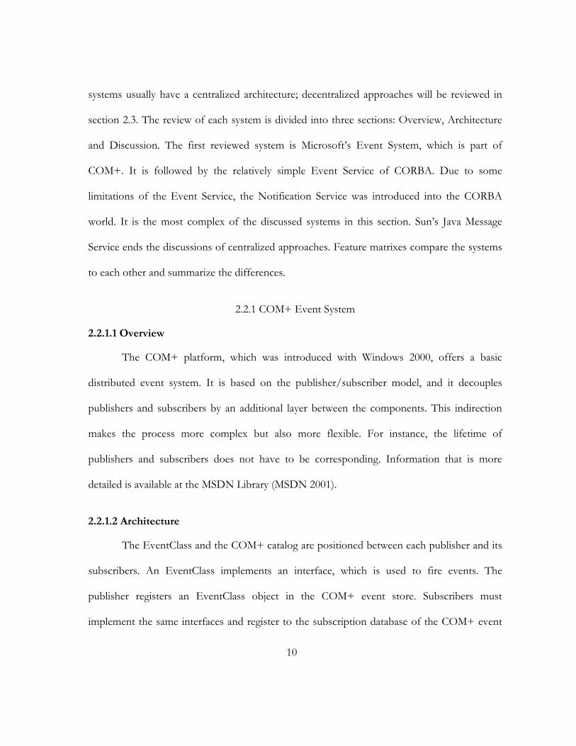
2.2.1.2 Architecture
The EventClass and the COM+ catalog are positioned between each publisher and its
subscribers. An EventClass implements an interface, which is used to fire events. The
publisher registers an EventClass object in the COM+ event store. Subscribers must
implement the same interfaces and register to the subscription database of the COM+ event
11
store. The EventClass object is persistent. The publisher and subscriber can be made
persistent, as well.
Figure 1. COM+ Events Architecture
The current version of the COM+ event store is not distributed. Subscribers have to
specify the computer to which they want to register. Thus, location transparency is not
supported. COM+ offers publisher and parameter filtering. Publisher filtering invokes the
filter(s) when the event is to be fired. The filters determine which subscribers are notified.
Parameter filtering allows subscribers to specify filters for parameters of each method. This
type of filtering is done after the publisher filtering and depends therefore on this preceding
step. To fire an event, the publisher creates an EventClass object and calls the desired method
of the event interface. The event system retrieves all the subscribers from the database and
invokes the method of each subscriber. This can happen serially or in parallel. Parallelism is
based on multi-threading. Together with the COM+ Queued Components Service, it is
possible to queue events in order to process them later. However, this requires extra effort as
a recorder and a player component must be placed between the other components.
12
2.2.1.3 Discussion
The COM+ system does not support distribution transparently. In COM+, events are
method calls. The overhead of method calls can be very small depending on the location of
the communication partners. It may be mapped to a local method call if publishers and
subscribers are in the same process. This does not require the creation of the event object.
However, in a distributed environment, this overhead is relatively low compared to preparing
the data and sending it over the network. Using message objects would be more flexible
because they can contain data and meta-data without forcing the listener to take care of them.
If a data field is added to a message class later, the listeners do not have to be adjusted.
Another advantage is that inheritance can be exploited with message objects. This allows
subscribers to receive and process events of sub-classes of the class, which they have
registered for in the first place, transparently.
2.2.2 CORBA Event Service
2.2.2.1 Overview
The motivation for this service is to provide an alternative method for standard
CORBA calls. This is explained in the “Event Service“ specification:
A standard CORBA request results in the synchronous execution of an operation by an object. If the operation defines parameters or return values, data is communicated between the client and the server. A request is directed to a particular object. For the request to be successful, both the client and the server must be available. If a request fails because the server is unavailable, the client receives an exception and must take some appropriate action. (OMG 2001)
13
CORBA’s Event Service provides a possibility to communicate asynchronously.
Events are sent from “Suppliers” to “EventChannels” and further to “Consumers”. This
indirect approach is similar to the COM+ solution. Both decouple senders from receivers and
their lifetimes. Besides the push model, CORBA also supports the pull model. However, this
will not be discussed any further, as it is not in the scope of this section.
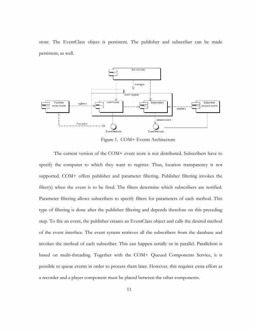
2.2.2.2 Architecture
The Event Service is a layer on top of ORB system; event delivery is done by ORB
calls. At a high level view, Consumers register to an EventChannel, to which Suppliers deliver
events (figure 2).
Figure 2. Basic Model of the CORBA Event Service
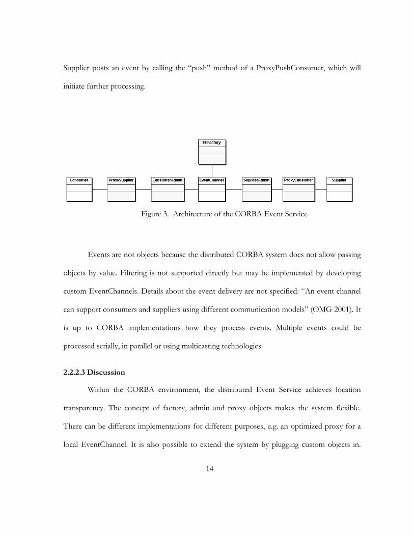
Several other objects are necessary. Firstly, the EventChannel must be obtained from a
Factory. The EventChannel object offers methods to retrieve so-called CosumerAdmin and
SupplierAdmin objects. These objects provide access to proxy objects. Depending on their
usage, they are called ProxyPushSupplier, ProxyPullSupplier, ProxyPushConsumer or
ProxyPullConsumer. Figure 3 illustrates this architecture. Suppliers are connected to
ProxyConsumers and Consumers are connected to ProxySuppliers. For example, a push
14
Supplier posts an event by calling the “push” method of a ProxyPushConsumer, which will
initiate further processing.
Figure 3. Architecture of the CORBA Event Service
Events are not objects because the distributed CORBA system does not allow passing
objects by value. Filtering is not supported directly but may be implemented by developing
custom EventChannels. Details about the event delivery are not specified: “An event channel
can support consumers and suppliers using different communication models” (OMG 2001). It
is up to CORBA implementations how they process events. Multiple events could be
processed serially, in parallel or using multicasting technologies.
2.2.2.3 Discussion
Within the CORBA environment, the distributed Event Service achieves location
transparency. The concept of factory, admin and proxy objects makes the system flexible.
There can be different implementations for different purposes, e.g. an optimized proxy for a
local EventChannel. It is also possible to extend the system by plugging custom objects in.

15
However, this concept is also less intuitive and requires more actions to be taken. Since
important features, like message filtering, are missing, the developer may use the plug-in
architecture for extending the service.
2.2.3 CORBA Notification Service
2.2.3.1 Overview
The Notification Service addresses several shortcomings of the Event Service. The
specification lists additional capabilities:
1. The ability to transmit events in the form of a well-defined data structure, in addition to Anys and Typed-events as supported by the existing Event Service.
2. The ability for clients to specify exactly which events they are interested in receiving, by attaching filters to each proxy in a channel.
3. The ability for the event types required by all consumers of a channel to be discovered by suppliers of that channel, so that suppliers can produce events on demand, or avoid transmitting events in which no consumers have interest.
4. The ability for the event types offered by suppliers to an event channel to be discovered by consumers of that channel so that consumers may subscribe to new event types as they become available.
5. The ability to configure various quality of service properties on a per-channel, per-proxy, or per-event basis.
6. An optional event type repository which, if present, facilitates the formation of filter constraints by end-users, by making information about the structure of events which will flow through the channel readily available.
(OMG 2000)
The most important improvements are the introduction of filters and the Quality-of-
Service parameters.
16
2.2.3.2 Architecture
The basic architecture is the same as the one of the Event Service, which was
discussed in the previous section in detail. Its goal was to be compatible with its predecessor:
The main design goal of the Notification Service architecture is to define the service as a direct extension of the existing OMG Event Service, enhancing the latter with important features which are required to satisfy a variety of applications with a broad range of scalability, performance, and quality of service (QoS) requirements. (OMG 2000, 2-1) The Notification Service defined here supports all of the interfaces and functionality supported by the OMG Event Service. In fact, an implementation of the Notification Service defined here can be thought of as subsuming an implementation of the Event Service. The Notification Service, however, also supports new features that are introduced by directly extending the interfaces defined by the Event Service. Both the original Event Service interfaces, and these new extended interfaces specific to Notification, are made available to Notification Service clients in order to preserve backward compatibility. (OMG 2000, 2-2)
Filters are implemented using the definition language “Extended TCL” (Trader
Constraint Language). They can be attached to all admin and proxy objects. Various Quality-
of-Service parameters were introduced: reliability, priority, expiration times, earliest delivery
time, maximum events per consumer, order policy, and discard policy. Another interesting
concept is “mapping filter objects”, which allows filters to influence Quality-of-Service
parameters like the message priority.
2.2.3.3 Discussion
The Notification Service is very complex and powerful. There are many interesting
features, but applications may not need all of them. For instance, Quality-of-Service
parameters, like exactly-once-delivery, increase the overhead and may not be required.
17
Altogether, it shares the complex architecture of the Event Service and overcomes its
shortcomings.
2.2.4 Java Message Service
2.2.4.1 Overview
The Java Message Service (JMS) is a specification (Sun 2001) developed by Sun. It
defines only the programming interface and is not an implementation itself. However, Sun’s
Java 2 Enterprise Edition includes an implementation and further ones are available from
various vendors. There are two groups of implementations. The first group wraps other
existing messaging systems and provides a JMS compliant interface to access them, for
example IBM’s MQSeries (IBM 2002) and Talarian’s SmartSockets for JMS (Talarian 2002).
The second group consists of native Java solutions and implements the functionality by
themselves, for example Sonic Software‘s SonicMQ (Sonic 2002) and IIT’s SwiftMQ (IIT
2002). JMS applications are portable within the bounds of the Java platform:
The primary portability objective is that new, JMS only, applications are portable across products within the same messaging domain. This is in addition to the expected portability of a JMS client across machine architectures and operating systems (when using the same JMS provider). (Sun 2001, 16)
Java Message Service offers two domains: point-to-point and publisher/subscriber
messaging. The point-to-point facilities of JMS are not in our scope and are therefore not
discussed here. Similar to the COM+ and the CORBA services, publishers and subscribers
communicate indirectly with each other to achieve a higher degree of decoupling.
18
2.2.4.2 Architecture
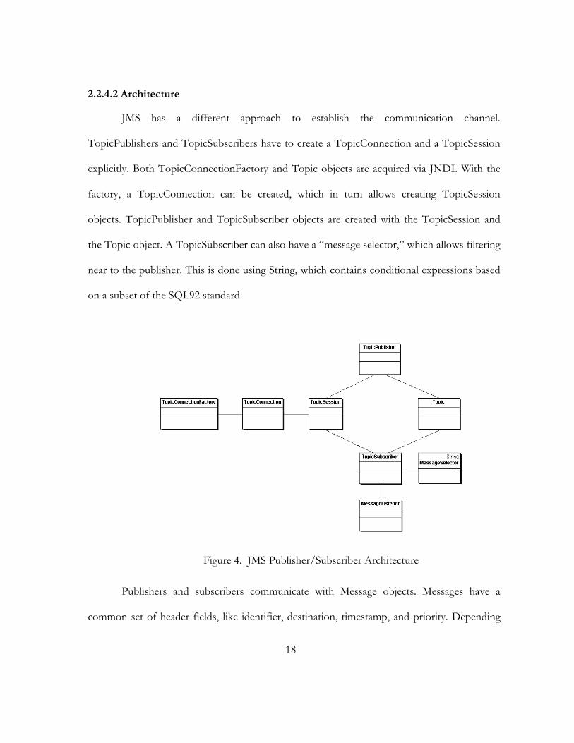
JMS has a different approach to establish the communication channel.
TopicPublishers and TopicSubscribers have to create a TopicConnection and a TopicSession
explicitly. Both TopicConnectionFactory and Topic objects are acquired via JNDI. With the
factory, a TopicConnection can be created, which in turn allows creating TopicSession
objects. TopicPublisher and TopicSubscriber objects are created with the TopicSession and
the Topic object. A TopicSubscriber can also have a “message selector,” which allows filtering
near to the publisher. This is done using String, which contains conditional expressions based
on a subset of the SQL92 standard.
Figure 4. JMS Publisher/Subscriber Architecture
Publishers and subscribers communicate with Message objects. Messages have a
common set of header fields, like identifier, destination, timestamp, and priority. Depending
19
on what data type is needed by the application, there are several subclasses of Message:
BytesMessage, TextMessage, MapMessage, StreamMessage, and ObjectMessage. Both
subscribers and messages can be made persistent to ensure an exact-once-delivery. Other
Quality-of-Service parameters are expiration time and message priorities.
2.2.4.3 Discussion
The Java Message Service offers important features, but is not as complex as
CORBA’s Notification Service. Following the specification, implementations can be relatively
efficient, depending on how the Connection, Session and Message classes are implemented.
The concepts of Connection and Session allow using techniques like TCP or UDP for
network communication. This may be more efficient than using RMI or ORB calls because it
implies lower overhead. However, it depends heavily on the implementation of the messaging
system, how the network communication is realized.
2.2.5 Feature Matrixes
The feature matrixes will summarize and complement the discussion of object
oriented messaging systems. They give a clear overview of the capabilities of the systems. The
compared features are separated in groups: General Features, Quality-of-Service parameters,
and Terms and Concepts. The gathered information is based on the official system
specifications (OMG 2000, OMG 2001, Sun 2001) and on the MSDN Library for COM+
Event System (MSDN 2001).
20
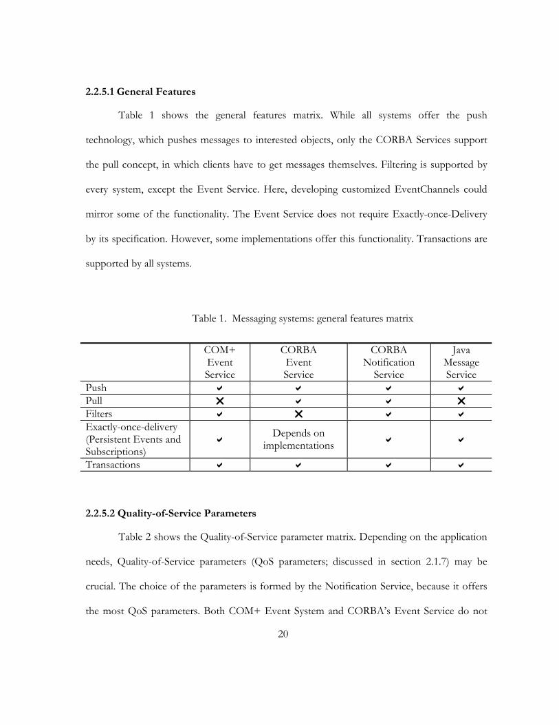
2.2.5.1 General Features
Table 1 shows the general features matrix. While all systems offer the push
technology, which pushes messages to interested objects, only the CORBA Services support
the pull concept, in which clients have to get messages themselves. Filtering is supported by
every system, except the Event Service. Here, developing customized EventChannels could
mirror some of the functionality. The Event Service does not require Exactly-once-Delivery
by its specification. However, some implementations offer this functionality. Transactions are
supported by all systems.
Table 1. Messaging systems: general features matrix
COM+ Event Service
CORBA Event Service
CORBA Notification
Service
Java Message Service
Push Pull Filters Exactly-once-delivery (Persistent Events and Subscriptions)
Depends on implementations
Transactions
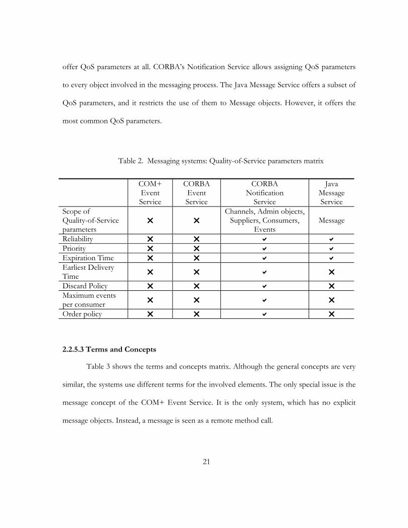
2.2.5.2 Quality-of-Service Parameters
Table 2 shows the Quality-of-Service parameter matrix. Depending on the application
needs, Quality-of-Service parameters (QoS parameters; discussed in section 2.1.7) may be
crucial. The choice of the parameters is formed by the Notification Service, because it offers
the most QoS parameters. Both COM+ Event System and CORBA’s Event Service do not
21
offer QoS parameters at all. CORBA’s Notification Service allows assigning QoS parameters
to every object involved in the messaging process. The Java Message Service offers a subset of
QoS parameters, and it restricts the use of them to Message objects. However, it offers the
most common QoS parameters.
Table 2. Messaging systems: Quality-of-Service parameters matrix
COM+ Event Service
CORBA Event Service
CORBA Notification
Service
Java Message Service
Scope of Quality-of-Service parameters
Channels, Admin objects,
Suppliers, Consumers, Events
Message
Reliability Priority Expiration Time Earliest Delivery Time
Discard Policy Maximum events per consumer
Order policy
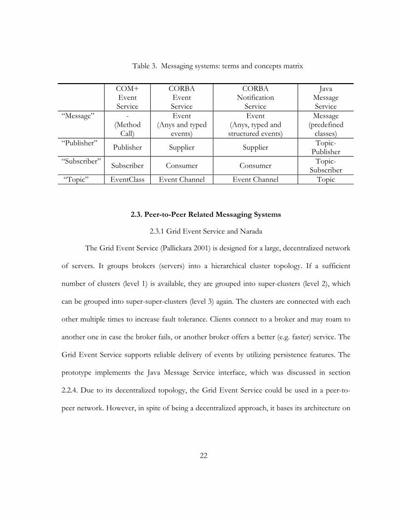
2.2.5.3 Terms and Concepts
Table 3 shows the terms and concepts matrix. Although the general concepts are very
similar, the systems use different terms for the involved elements. The only special issue is the
message concept of the COM+ Event Service. It is the only system, which has no explicit
message objects. Instead, a message is seen as a remote method call.
22
Table 3. Messaging systems: terms and concepts matrix
COM+ Event Service
CORBA Event Service
CORBA Notification
Service
Java Message Service
“Message” - (Method
Call)
Event (Anys and typed
events)
Event (Anys, typed and structured events)
Message (predefined
classes) “Publisher” Publisher Supplier Supplier Topic-
Publisher “Subscriber” Subscriber Consumer Consumer Topic-
Subscriber “Topic” EventClass Event Channel Event Channel Topic
2.3. Peer-to-Peer Related Messaging Systems
2.3.1 Grid Event Service and Narada
The Grid Event Service (Pallickara 2001) is designed for a large, decentralized network
of servers. It groups brokers (servers) into a hierarchical cluster topology. If a sufficient
number of clusters (level 1) is available, they are grouped into super-clusters (level 2), which
can be grouped into super-super-clusters (level 3) again. The clusters are connected with each
other multiple times to increase fault tolerance. Clients connect to a broker and may roam to
another one in case the broker fails, or another broker offers a better (e.g. faster) service. The
Grid Event Service supports reliable delivery of events by utilizing persistence features. The
prototype implements the Java Message Service interface, which was discussed in section
2.2.4. Due to its decentralized topology, the Grid Event Service could be used in a peer-to-
peer network. However, in spite of being a decentralized approach, it bases its architecture on
23
broker and clients. Further, the Grid Event Service does not address heterogeneous networks.
Therefore, its usability is restricted in peer-to-peer networks.
Narada (Fox and others 2002, Fox and Pallickara 2002a) is based on the Grid Event
Service. Like its predecessor, it implements the Java Message Service, as well (Fox and
Pallickara 2002b). The main extension is the integration with the peer-to-peer platform JXTA
(see section 2.3.4). While Narada extends its platform to peer-to-peer, it also services JXTA by
providing an additional message delivery mechanism. The fundamental concept is the
“Narada-JXTA proxy,” which is both JXTA rendezvous peer and Narada client. The proxy
forwards incoming JXTA messages to others using the Narada infrastructure. Therefore, the
two platforms can interchange messages and collaborate. However, this approach does not
address improving messaging directly inside peer-to-peer networks. Instead, it utilizes its
broker infrastructure and offers a bridge to the peer-to-peer network.
2.3.2 Siena
Siena (Carzaniga 1998, Carzaniga, Rosenblum and Wolf 2001) is a publish/subscribe
messaging system based on a content-based networking approach (Carzaniga and Wolf 2001).
Unlike topic based publish/subscribe systems, the recipients are not identified by group
membership in Siena. Instead, subscribers receive only the messages (called events in Siena),
which match a subscriber-specific content pattern called event filters. Events are a set of
attributes consisting of a type, a name, and a value. These attributes are compared to filter
constraints, which consist of a type, a name, a value, and an operator. If the event does not
match a subscriber’s filter constraints, the event will not be delivered to this subscriber. Before
24
publishing events, the publisher will advertise a set of all possible events it will emit. Thus,
subscriptions not matching the advertisement do not have to be considered for this publisher.
Siena’s infrastructure consists of connected server clusters, similar to the approach of the Grid
Event Service/Narada. However, the topologies of the cluster can vary. Currently, Siena
supports hierarchical server, general peer-to-peer and acyclic peer-to-peer topologies.
Although servers can be connected in a peer-to-peer fashion, Siena clearly differentiates
between dedicated servers and clients. Its usability in peer-to-peer networks is further
restricted by the lack of failure robustness and heterogeneity considerations.
2.3.3 Pastry and Scribe
Scribe (Rowstron and others 2001) from Microsoft Research is a topic-centric
publish/subscribe messaging system based on the peer-to-peer platform Pastry (Rowstron and
Druschel 2001). Pastry utilizes routing mechanisms to achieve a greater scalability than earlier
approaches like Gnutella (Gnutella). Similar emerging peer-to-peer systems are Gridella
(Aberer and others 2002), CAN (Ratnasamy and others 2001), Chord (Stoica and others
2001), and Tapestry (Zhao 2001). Each Pastry node stores routing information in a routing
table containing information about distant peers and a leaf set containing its direct neighbors.
Scribe depends on Pastry to route messages to their destinations. Topics are accessed with a
unique ID, which consists of the hash of the topic’s textual name and its creator’s name.
Scribe elects the Pastry node, whose ID is numerical closest to the topic ID, as the topic
rendezvous point and root of the multicast-tree. The multicast-tree is created for each topic
using a mechanism similar to reverse path forwarding (Dalal and Metcalf 1978). Each Scribe

25
subscriber is connected to the root via one or many Pastry connections. These routes include
nodes, which may or may not be subscribers. A message going to be published is forwarded to
the multicast-tree root using the Pastry connections, or it may be sent directly if the root is
known to the publisher. In summary, Scribe forwards messages using the peer-to-peer
platform Pastry, which is capable of routing. This approach has several disadvantages. It does
not overcome the limitations of peer-to-peer networks in the messaging domain, which will be
discussed in detail in chapter 4. Further, the multicasting tree is formed without considering
efficiency issues. It imposes a higher workload especially to the root and the nodes near to it
without determining whether they are powerful enough. Overloaded nodes may decrease the
efficiency for message delivery. Therefore, this system seems limited to applications requiring
only low efficiency requirements.
2.3.4 JXTA
JXTA (JXTA 2002, Sun 2002) is an open all-purpose peer-to-peer platform. The
protocol is available to the public, and it is independent of any programming language and
platform. The reference implementation is developed in Java. However, it is currently ported
to C, Objective C, Smalltalk, and Perl. JXTA is not a messaging system, but there exist some
analogies to them. In addition to peers, it introduces the concept of rendezvous and peers,
which offer additional functionalities, like forwarding discovery requests and routing. Both,
rendezvous and relay peers, have to be set up explicitly. As JXTA is a general network, it has
to separate peers of a common application. This is done using peer groups. The
“NetPeerGroup” is a special group that all peers belong to. Nevertheless, peers may
26
participate in any number of other groups. There is also a group authorization mechanism
evolved, which can be extended to provide one that fulfills individual needs. Other central
aspects are advertisements, which are based on XML documents and are identified by a
unique identifier. Each resource, like peers, peer groups, and data resources, is made available
by publishing advertisements. Peers may look up these advertisements by sending discovery
messages. The common communication practices are “pipes,” which hide the message
delivery by the peer-to-peer network from users. The delivery includes routing through the
peer nodes, and adjusting the route due to node failures. JXTA differentiates between input
and output pipes, and between unicast and multicast communication. The multicast solution is
called “propagate pipe,” which allows several peers to listen to it. Pipes like the propagation
pipe are not reliable; messages may be lost without any notification. To avoid this situation,
JXTA offers special pipes with a higher degree of reliability. However, these reliable pipes are
currently restricted to unicast. JXTA is an emerging technology and has to be studied further.
It has many interesting aspects that still have to prove their usability in practice. However,
because of rendezvous/relay peers, routing, and caching, JXTA has the potential to become a
scalable peer-to-peer platform.
2.3.5 Feature Matrixes
The feature matrixes in table 4 and 5 summarize and complement the discussion on
the systems, which are related to peer-to-peer concepts. The first comparison includes general
criteria, while the second one includes conceptual group communication aspects especially
relevant in peer-to-peer networks.
27
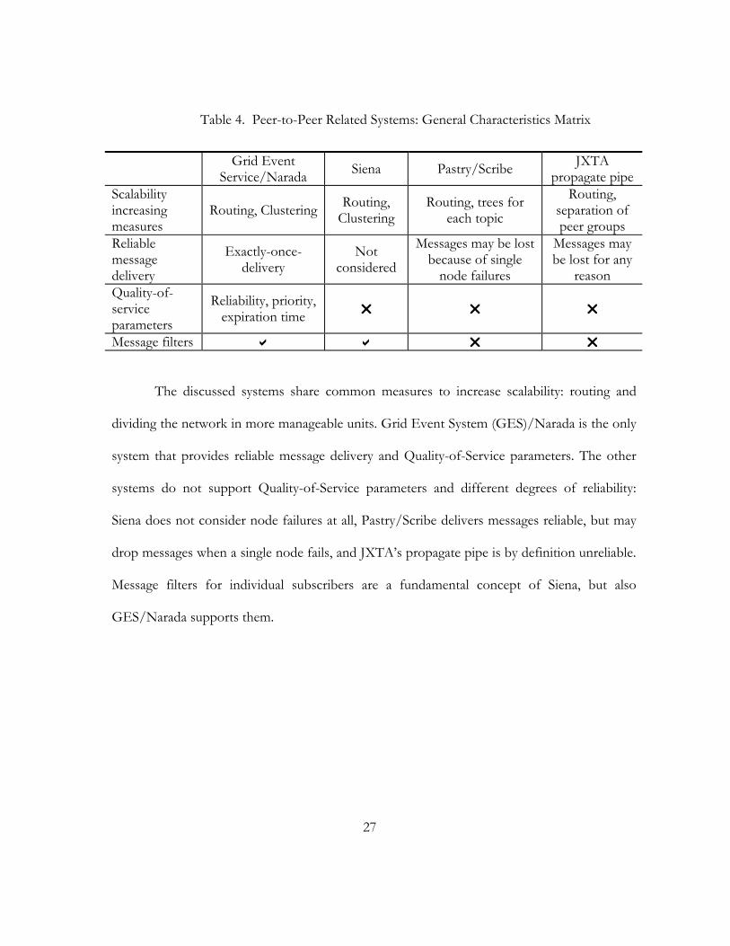
Table 4. Peer-to-Peer Related Systems: General Characteristics Matrix
Grid Event Service/Narada Siena Pastry/Scribe JXTA
propagate pipeScalability increasing measures
Routing, Clustering Routing, Clustering
Routing, trees for each topic
Routing, separation of peer groups
Reliable message delivery
Exactly-once-delivery
Not considered
Messages may be lost because of single
node failures
Messages may be lost for any
reason Quality-of-service parameters
Reliability, priority, expiration time
Message filters
The discussed systems share common measures to increase scalability: routing and
dividing the network in more manageable units. Grid Event System (GES)/Narada is the only
system that provides reliable message delivery and Quality-of-Service parameters. The other
systems do not support Quality-of-Service parameters and different degrees of reliability:
Siena does not consider node failures at all, Pastry/Scribe delivers messages reliable, but may
drop messages when a single node fails, and JXTA’s propagate pipe is by definition unreliable.
Message filters for individual subscribers are a fundamental concept of Siena, but also
GES/Narada supports them.
28
Table 5. Peer-to-Peer Related Systems: Group Communication Characteristics Matrix
Grid Event Service/Narada Siena Pastry/Scribe JXTA
propagate pipe Topology
Broker clusters Hybrid clusters
Tree built on peer-to-peer
network Peer-to-peer
Group formation Topic subscription
Content based
Topic subscription
Peer group membership,
propagate pipe Node roles Brokers and
clients
Servers and
clients Peers
Peers, rendezvous/router
peers Multicast messages traverse only nodes in the group
Heterogeneity of nodes considered
Adjustment to node failures Client roams to
another broker Local
restoration of subscriptions
(Insufficient information
available)
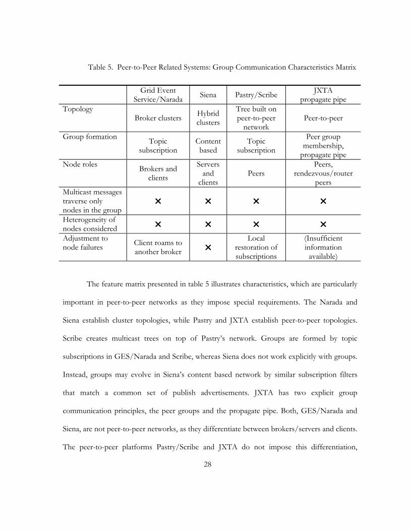
The feature matrix presented in table 5 illustrates characteristics, which are particularly
important in peer-to-peer networks as they impose special requirements. The Narada and
Siena establish cluster topologies, while Pastry and JXTA establish peer-to-peer topologies.
Scribe creates multicast trees on top of Pastry’s network. Groups are formed by topic
subscriptions in GES/Narada and Scribe, whereas Siena does not work explicitly with groups.
Instead, groups may evolve in Siena’s content based network by similar subscription filters
that match a common set of publish advertisements. JXTA has two explicit group
communication principles, the peer groups and the propagate pipe. Both, GES/Narada and
Siena, are not peer-to-peer networks, as they differentiate between brokers/servers and clients.
The peer-to-peer platforms Pastry/Scribe and JXTA do not impose this differentiation,

29
although JXTA relies on rendezvous/router peers, which take care of additional tasks. None
of the presented systems adjusts its network in order to avoid traversing nodes, which are not
part of a group. The additional traversed nodes slow down the delivery process. Further, none
of the systems considers heterogeneity among the nodes, which is typically found in peer-to-
peer networks. Adjustment to node failures is handled differently by each system. If message
broker fails in GES/Narada, the broker’s clients can roam to another broker. Pastry/Scribe
handle failures by repairing the multicast tree: failed parent nodes require their child nodes to
renew their subscription at a new node higher in the tree hierarchy. Siena does not support
repair mechanisms. As JXTA is not completely documented, the available information was
not sufficient to determine its character regarding node failures.
The feature matrixes showed that the peer-to-peer related systems do not provide
optimal solutions for group communications. Despite their scalable characters, GES/Narada
and Siena are not intended as peer-to-peer systems. The peer-to-peer networks Pastry/Scribe
and JXTA lack general features, and do not consider several characteristics of peer-to-peer
networks.
2.4. Summary
This chapter introduced basic principles, a comparison of common messaging systems
in the object-oriented middleware domain, and emerging peer-to-peer approaches. The first
major part of this chapter reviewed messaging systems related to object-oriented middleware.
We discussed the COM+ Event Service, which is part of Windows. Then, we looked at two
CORBA solutions: the simple Event Service and the powerful Notification Service. The Java
30
Message Service, which is implemented by many systems, offers important features. These
systems were compared in feature matrixes. The second major part of the chapter investigated
related work in conjunction with the peer-to-peer domain. We discussed the messaging
systems Grid Event Service, its predecessor Narada, and Siena. All of them are based on
scalable server clusters, but none of them reflects the pure peer-to-peer concept. Scribe is built
on the peer-to-peer platform Pastry, but has efficiency issues due to the formation of its
multicast tree. JXTA, an all-purpose peer-to-peer platform, allows the formation of peer
groups and multicast communication. Lastly, the peer-to-peer related systems were compared
in feature matrixes, which revealed that they share deficiencies in the peer-to-peer domain.

31
CHAPTER III
A SERVER-LESS MESSAGING SYSTEM
In this chapter, a prototype of a messaging system will be built. Concepts, models and
algorithms will be presented and alternatives will be discussed. After defining the
requirements, we will describe the basic model from a high-level view. Then we will discuss
important concepts in detail. The focus is set to messages, and how they are transmitted to
their destinations using various concepts. In the end, results will be discussed.
3.1. Requirements
The motivation is to create a server-less and high performance messaging system build
on the publisher/subscriber model. Based on these fundamental principles (requirements 1-3),
we can refine and extend the requirements (requirements 4-9).
1. Publisher/subscriber concept
2. Server-less network architecture
3. Emphasis on high performance
4. Message filtering for each subscriber near to the publisher in order to save unnecessary network traffic.
5. Event priorities. Events with a higher priority will be delivered sooner than events with a lower priority.
6. Allow different types of connections in order to allow efficient communication depending on the environment.
7. Utilize low-level connection types like TCP, UDP and intra-process to reduce overhead to a minimum.
32
8. A Quality-of-Service parameter to distinguish between essential and non-essential events. Not essential events may be lost during transportation. This allows network optimization, for instance using UDP instead of TCP.
9. Allow new connections types to be plugged into the system in order to allow adjusting to changed environments efficiently.
3.2. Extended Publisher/Subscriber Model
This section illustrates basic concepts, and addresses fundamental problems and
alternatives. The scenario is based on a topic-centric publisher/subscriber model. A publisher
sends messages associated to a topic. Interested objects can subscribe to a topic, receive
messages from a topic and unsubscribe from a topic. For some applications, it may be
necessary to send messages back to the publishing application. We will investigate in this
practice because it may result in an efficient solution for two-way communication. The
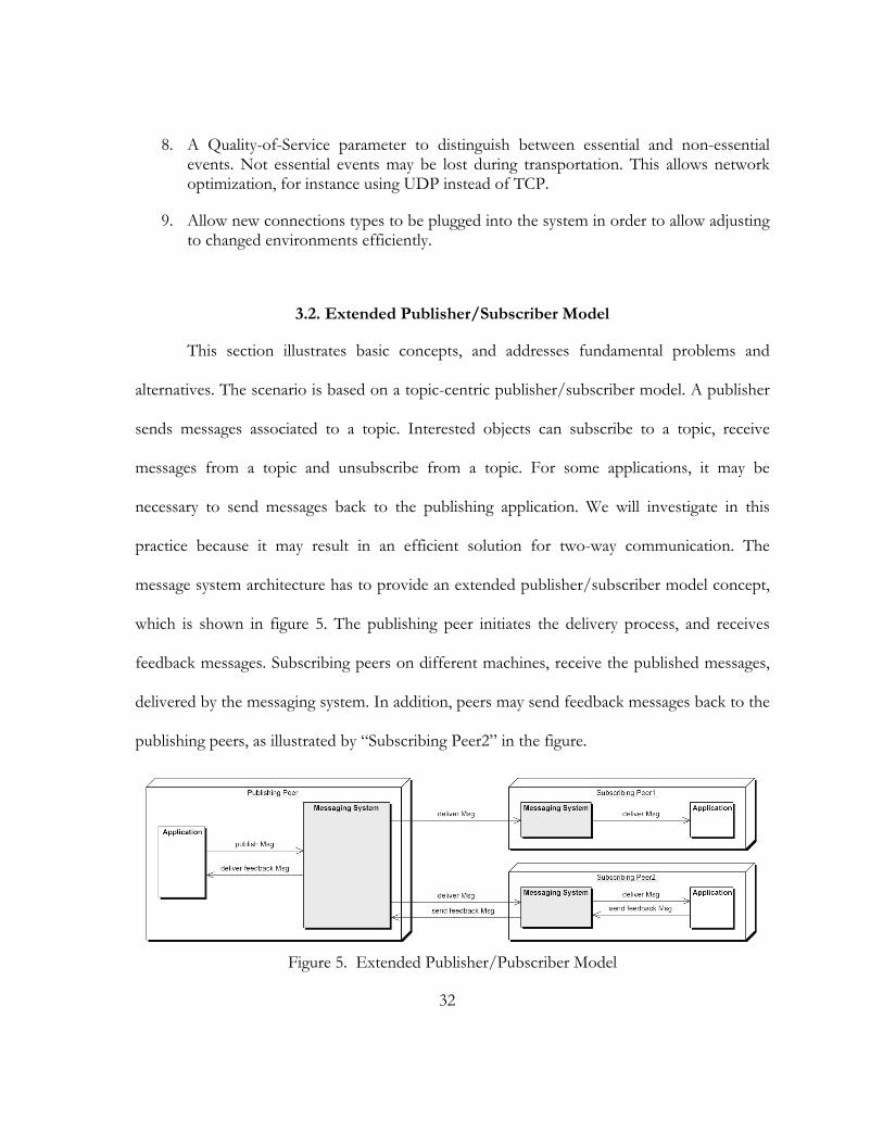
message system architecture has to provide an extended publisher/subscriber model concept,
which is shown in figure 5. The publishing peer initiates the delivery process, and receives
feedback messages. Subscribing peers on different machines, receive the published messages,
delivered by the messaging system. In addition, peers may send feedback messages back to the
publishing peers, as illustrated by “Subscribing Peer2” in the figure.
Figure 5. Extended Publisher/Pubscriber Model
33
3.2.1 Potential Solution: pure Publisher/Subscriber and a Feedback Topic
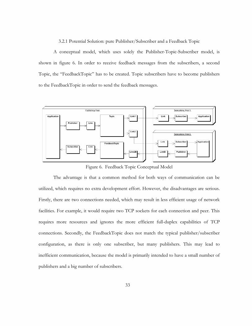
A conceptual model, which uses solely the Publisher-Topic-Subscriber model, is
shown in figure 6. In order to receive feedback messages from the subscribers, a second
Topic, the “FeedbackTopic” has to be created. Topic subscribers have to become publishers
to the FeedbackTopic in order to send the feedback messages.
Figure 6. Feedback Topic Conceptual Model
The advantage is that a common method for both ways of communication can be
utilized, which requires no extra development effort. However, the disadvantages are serious.
Firstly, there are two connections needed, which may result in less efficient usage of network
facilities. For example, it would require two TCP sockets for each connection and peer. This
requires more resources and ignores the more efficient full-duplex capabilities of TCP
connections. Secondly, the FeedbackTopic does not match the typical publisher/subscriber
configuration, as there is only one subscriber, but many publishers. This may lead to
inefficient communication, because the model is primarily intended to have a small number of
publishers and a big number of subscribers.
34
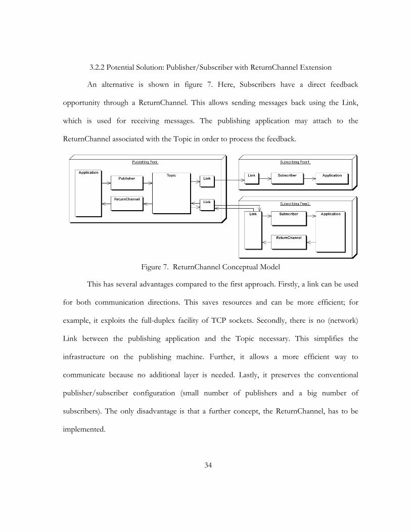
3.2.2 Potential Solution: Publisher/Subscriber with ReturnChannel Extension
An alternative is shown in figure 7. Here, Subscribers have a direct feedback
opportunity through a ReturnChannel. This allows sending messages back using the Link,
which is used for receiving messages. The publishing application may attach to the
ReturnChannel associated with the Topic in order to process the feedback.
Figure 7. ReturnChannel Conceptual Model
This has several advantages compared to the first approach. Firstly, a link can be used
for both communication directions. This saves resources and can be more efficient; for
example, it exploits the full-duplex facility of TCP sockets. Secondly, there is no (network)
Link between the publishing application and the Topic necessary. This simplifies the
infrastructure on the publishing machine. Further, it allows a more efficient way to
communicate because no additional layer is needed. Lastly, it preserves the conventional
publisher/subscriber configuration (small number of publishers and a big number of
subscribers). The only disadvantage is that a further concept, the ReturnChannel, has to be
implemented.
35
3.2.3 Decision: ReturnChannel Extension
Offering a ReturnChannel is the better approach. It is more efficient because one
Connection can be used for both communication directions. This supports the primary goals
for the component: efficiency and low overhead. Further, it offers a more intuitive and easier-
to-use approach for sending feedback.
3.3. Concepts and Models in Detail
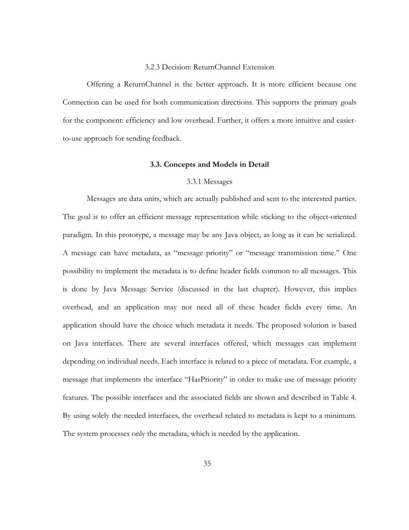
3.3.1 Messages
Messages are data units, which are actually published and sent to the interested parties.
The goal is to offer an efficient message representation while sticking to the object-oriented
paradigm. In this prototype, a message may be any Java object, as long as it can be serialized.
A message can have metadata, as “message priority” or “message transmission time.” One
possibility to implement the metadata is to define header fields common to all messages. This
is done by Java Message Service (discussed in the last chapter). However, this implies
overhead, and an application may not need all of these header fields every time. An
application should have the choice which metadata it needs. The proposed solution is based
on Java interfaces. There are several interfaces offered, which messages can implement
depending on individual needs. Each interface is related to a piece of metadata. For example, a
message that implements the interface “HasPriority” in order to make use of message priority
features. The possible interfaces and the associated fields are shown and described in Table 4.
By using solely the needed interfaces, the overhead related to metadata is kept to a minimum.
The system processes only the metadata, which is needed by the application.
36
Table 4. Message Interface Types and their Fields
Interface Field Set by Description HasSendTime SendTime Sender, adjusted by
the receiver Timestamp when the message was sent
HasSendTime TimeSinceSend Dynamic by the message
Milliseconds since the message was sent
HasEssentialFlag Essential User Flag whether the Message is essential
HasAcknowledgement AcknowledgeMode User Determines whether the message has to be acknowledged
HasPriority Priority User Message priority
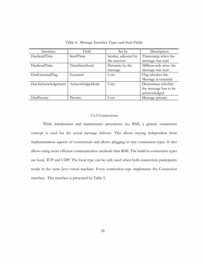
3.3.2 Connections
While initialization and maintenance procedures use RMI, a generic connection
concept is used for the actual message delivery. This allows staying independent from
implementation aspects of connections and allows plugging in new connection types. It also
allows using more efficient communication methods than RMI. The build-in connection types
are local, TCP and UDP. The local type can be only used when both connection participants
reside in the same Java virtual machine. Every connection type implements the Connection
interface. This interface is presented by Table 5.
37
Table 5. Fields of the Connection interface
Field Description isReliable() Flag whether this connection offers reliable
communication getAlias() A String to identify the Connection, e.g.
“TCP”, “UDP”, “RMI”, “CORBA”, “LOCAL”
send(Object msg) Sends a message setReceiver(MessageReceiver receiver) Sets the message receiver, which will be
called when an event arrives setLatency(int latency) During the initialization, the latency is
determined and set by the system getLatency() Latency in milliseconds
3.3.2.1 Connection Wrapper Concept
Connection wrappers help creating full functional connections. Developers, who want
implement new connection types, can use them to reduce their programming effort. The
wrappers provide basic functionality, which can be reused for several connection types. The
system depends on queued connections capable of sending and receiving objects. However, it
is possible to construct less functional connection types and put the necessary wrappers
around them. The available types and wrappers are illustrated by figure 8.
The StreamConnection type does not offer sending Objects. Instead, it offers low-
level Input- and OutputStreams for sending and receiving already encoded messages. The
wrapper class StreamConnectionWrapper can be used with a StreamConnection. It encodes
and decodes Messages and delegates the sending and receiving to the attached
StreamConnection. The wrapper implements the Connection type, which sends and receives
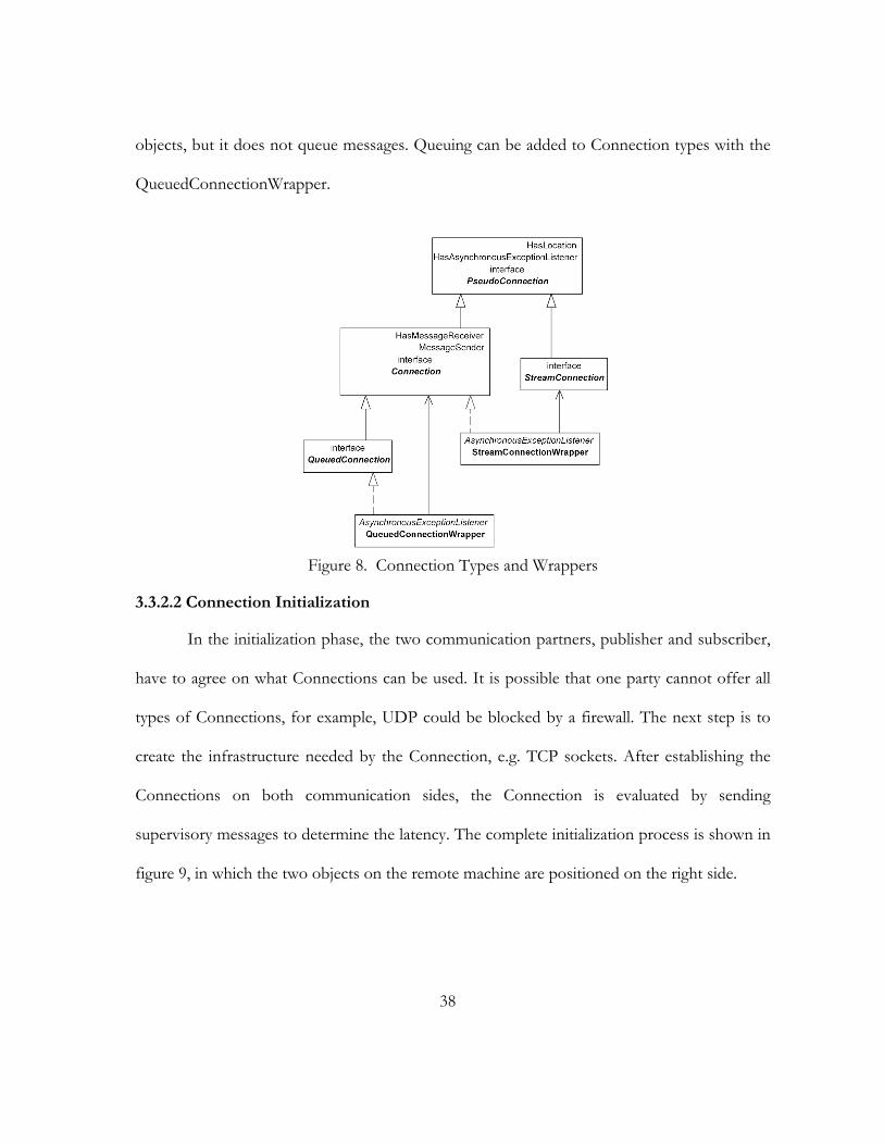
38
objects, but it does not queue messages. Queuing can be added to Connection types with the
QueuedConnectionWrapper.
Figure 8. Connection Types and Wrappers
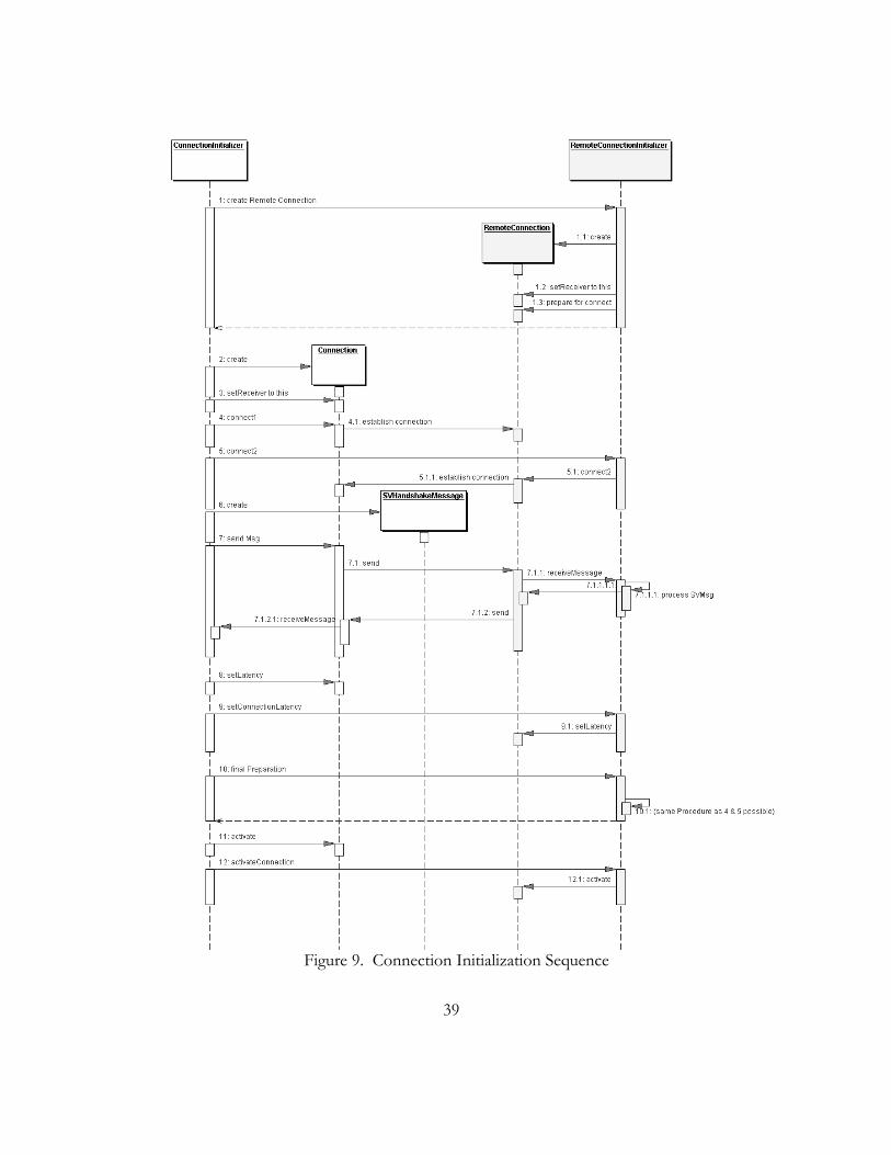
3.3.2.2 Connection Initialization
In the initialization phase, the two communication partners, publisher and subscriber,
have to agree on what Connections can be used. It is possible that one party cannot offer all
types of Connections, for example, UDP could be blocked by a firewall. The next step is to
create the infrastructure needed by the Connection, e.g. TCP sockets. After establishing the
Connections on both communication sides, the Connection is evaluated by sending
supervisory messages to determine the latency. The complete initialization process is shown in
figure 9, in which the two objects on the remote machine are positioned on the right side.
39
Figure 9. Connection Initialization Sequence

40
3.3.3 Links: Multiple Connections
A Link consists of multiple connections between the two communication partners.
The concept of using multiple connections allows choosing an optimal one for specific needs.
For example, an unreliable UDP connection can be used for transmitting non-essential
messages, while a reliable TCP connection is used for transmitting the essential ones. Another
application for this concept could be to differentiate between sensitive and insensitive
messages, which require either slow and secure, or fast and insecure connections.
3.3.3.1 Algorithms for choosing a Connection
Introducing multiple connections leads to the question, which connections should be
used for which messages. The selection method should not depend on any connection type
and should allow working with connections, which were plug-in by the user. This connection
selection can depend on several parameters: the message type, Quality-of-Service parameters,
connection negotiation results from the initialization phase, and user settings. There are
several algorithms possible, which have to be considered:
1. ConnectionSelector. The ConnectionSelector makes the decision. If another behavior is needed, a new ConnectionSelector must be plugged in.
2. Ask Connections. A ConnectionSelector asks the available Connections whether they are suited to send a specific Message. However, it is difficult to choose one if more then one Connection is suited. Another drawback is that the behavior is hard-wired into the Connections.
3. Self-describing Connections. Connections have parameters like reliability, latency, data-overhead and speed. The system chooses the most appropriate connection by itself. This approach offers a great flexibility, but it is also relatively complex. In addition, it does not allow the user to adjust the behavior to specific needs. A similar approach would be the “Sponsor-Selector” pattern (Martin 1998).

41
4. Connection Priorities. The Connections have priorities. The Connection with the highest priority is selected. It would be easy to plug-in new Connections, but the behavior is tied to the Connection.
5. Lists of preferred Connections. The ConnectionSelector has lists, which store the Connections ordered by how well they suit the needs. The user can modify the list if this is needed for special purposes. In addition, the user is forced to update at least one list when adding a new Connection.
6. Evaluate Connections. After the Connections are setup, the Connections are evaluated. For example, the roundtrip time could be determined. Based on that information the optimal Connection could be selected.
7. Combinations. There is also a variety of combinations possible. For instance, a default ConnectionSelector, which can be replaced, could evaluate the Connections and create a default list of preferred Connections, which could still be modifiable by the user.
3.3.3.2 Chosen Algorithm: ConnectionSelector Combination
The probably most important influence for the decision is whether the Message has to
be delivered reliable by the network or not. Therefore, it makes sense to pre-select the
Connection depending on this parameter. The “Evaluate Connections” principle seems the
most appropriate solution because it emphases the efficiency goal of the Message Component
and it makes it easy to plug-in new a Connection into the Component. To meet other
application needs, a plug-in mechanism for a new ConnectionSelector will be supported.
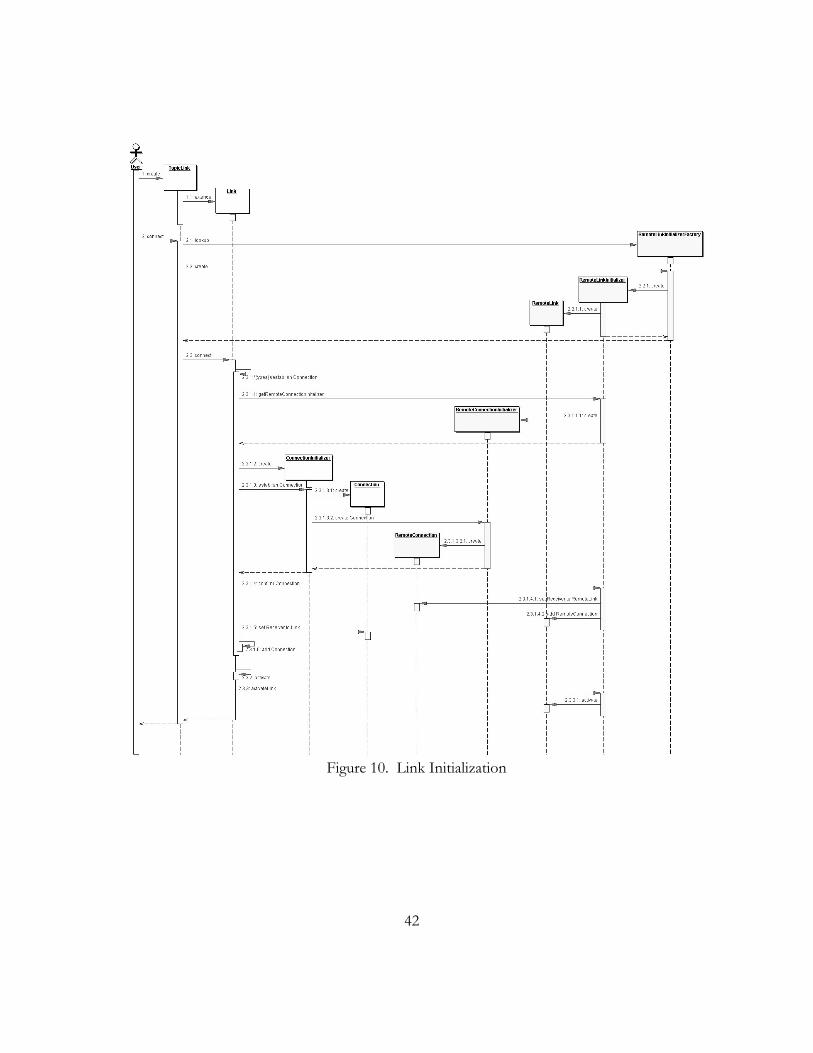
3.3.3.3 Link Initialization
The link initialization process (figure 10) requires several steps. After setting up the
basic Link objects on the local and the remote side, the connections have to be initialized. The
connection initialization was discussed in the last section. Successfully initialized connections
are added to the Link objects on both local and remote sides.
42
Figure 10. Link Initialization
43
3.3.4 Message Delivery
3.3.4.1 Publishing and Filtering Messages
The process of publishing messages is shown in figure 11. The application passes the
message to a Publisher object. The Publisher has a list of all subscribers and delivers the
message to all of them. The Publisher itself does not know which subscribers are at a remote
location. Subscribers on a remote machine are represented by RemoteSubscribers. A
RemoteSubscriber is a proxy, which hides the remote behavior. It passes the message to the
Link, which adjusts the message fields and passes the message to the chosen Connection. The
Connection simply puts the message in a queue at this time to let the application continue
with its work. The Connection has its own sender thread, which will retrieve messages from
the queue and sends them sequentially to the remote Connection object.
Message filtering is involved in the publishing process, as well. Filters allow sending
only the messages, in which a specific subscriber is interested. This is an important
optimization, because network traffic can be avoided, which results in saving bandwidth and
processing power. One approach could be a to use logical expressions based on text
definitions, as applied in Java Message Service (Sun 2001, 37-43). However, we chose to use
Java objects as filters, since they allow a greater flexibility and performance. Each subscriber
can send a filter object to the publisher. During the publishing process (figure 11), the
publisher will ask each filter object whether a message should be sent.
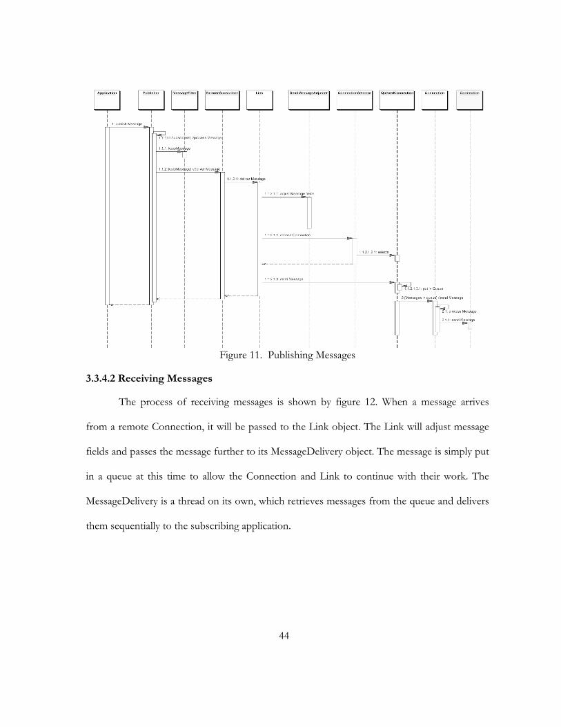
44
Figure 11. Publishing Messages
3.3.4.2 Receiving Messages
The process of receiving messages is shown by figure 12. When a message arrives
from a remote Connection, it will be passed to the Link object. The Link will adjust message
fields and passes the message further to its MessageDelivery object. The message is simply put
in a queue at this time to allow the Connection and Link to continue with their work. The
MessageDelivery is a thread on its own, which retrieves messages from the queue and delivers
them sequentially to the subscribing application.
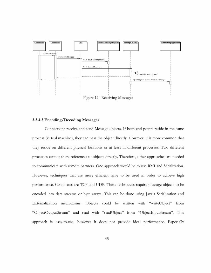
45
Figure 12. Receiving Messages
3.3.4.3 Encoding/Decoding Messages
Connections receive and send Message objects. If both end-points reside in the same
process (virtual machine), they can pass the object directly. However, it is more common that
they reside on different physical locations or at least in different processes. Two different
processes cannot share references to objects directly. Therefore, other approaches are needed
to communicate with remote partners. One approach would be to use RMI and Serialization.
However, techniques that are more efficient have to be used in order to achieve high
performance. Candidates are TCP and UDP. These techniques require message objects to be
encoded into data streams or byte arrays. This can be done using Java’s Serialization and
Externalization mechanisms. Objects could be written with “writeObject” from
“ObjectOutputStream” and read with “readObject” from “ObjectInputStream”. This
approach is easy-to-use, however it does not provide ideal performance. Especially
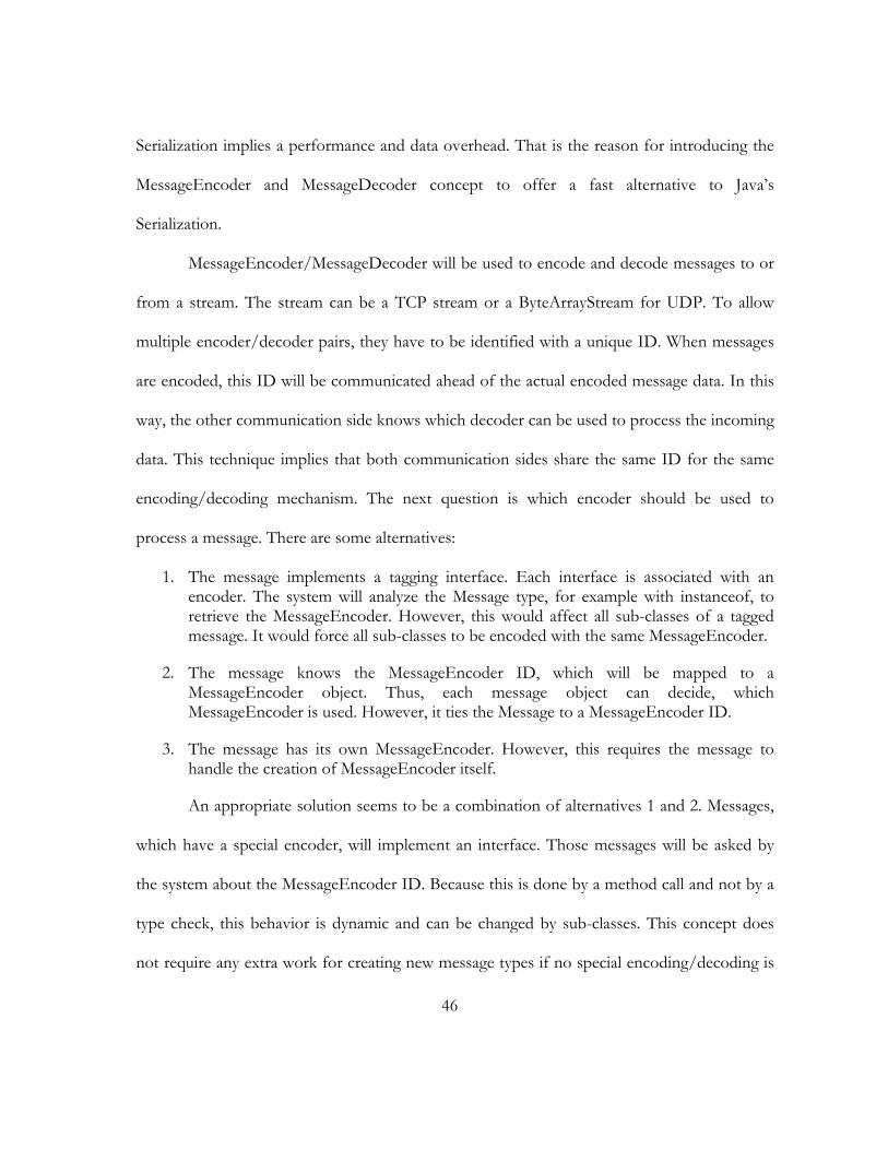
46
Serialization implies a performance and data overhead. That is the reason for introducing the
MessageEncoder and MessageDecoder concept to offer a fast alternative to Java’s
Serialization.
MessageEncoder/MessageDecoder will be used to encode and decode messages to or
from a stream. The stream can be a TCP stream or a ByteArrayStream for UDP. To allow
multiple encoder/decoder pairs, they have to be identified with a unique ID. When messages
are encoded, this ID will be communicated ahead of the actual encoded message data. In this
way, the other communication side knows which decoder can be used to process the incoming
data. This technique implies that both communication sides share the same ID for the same
encoding/decoding mechanism. The next question is which encoder should be used to
process a message. There are some alternatives:
1. The message implements a tagging interface. Each interface is associated with an encoder. The system will analyze the Message type, for example with instanceof, to retrieve the MessageEncoder. However, this would affect all sub-classes of a tagged message. It would force all sub-classes to be encoded with the same MessageEncoder.
2. The message knows the MessageEncoder ID, which will be mapped to a MessageEncoder object. Thus, each message object can decide, which MessageEncoder is used. However, it ties the Message to a MessageEncoder ID.
3. The message has its own MessageEncoder. However, this requires the message to handle the creation of MessageEncoder itself.
An appropriate solution seems to be a combination of alternatives 1 and 2. Messages,
which have a special encoder, will implement an interface. Those messages will be asked by
the system about the MessageEncoder ID. Because this is done by a method call and not by a
type check, this behavior is dynamic and can be changed by sub-classes. This concept does
not require any extra work for creating new message types if no special encoding/decoding is

47
necessary. In this case, the default MessageEncoders/MessageDecoders can be applied. They
will offer a general solution to encode/decode Java Objects because they are using the
standard Java Serialization/Externalization procedures.
3.3.4.3.1 MessageEncoder/MessageDecoder Model
Figure 13 shows an UML class diagram of the classes, which are involved in the
encoding/decoding procedure. The interface UseCustomMessageEncoder can be
implemented by messages, for which a special encoder/decoder pair exists. There are two
concrete implementations of the interface MessageEncoderDecoder. SerializationMessage-
EncoderDecoder is based on Java’s Serialization and is the default mechanism used to process
messages. ComponentMessageEncoderDecoder is used for message types, which are offered
by the system. It implements a faster encoding/decoding mechanism. The MessageEncoder-
DecoderStore is used to manage the available MessageEncoderDecoders. All
MessageEncoderDecoder have to be registered at this object before they can be used. The
MessageWriterReaderImpl class provides functionality to write and read messages to or from
streams. Internally, it fetches the necessary MessageEncoderDecoder object from the
MessageEncoderDecoderStore depending on the message and delegates the process to it.
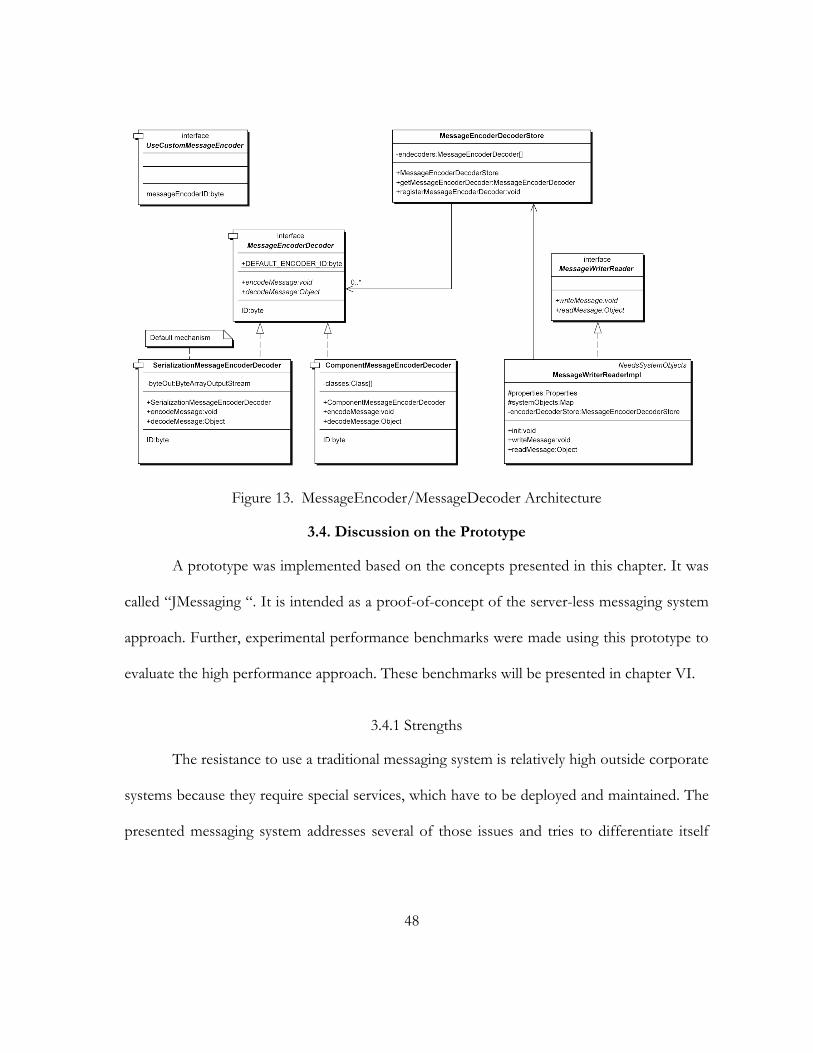
48
Figure 13. MessageEncoder/MessageDecoder Architecture
3.4. Discussion on the Prototype
A prototype was implemented based on the concepts presented in this chapter. It was
called “JMessaging “. It is intended as a proof-of-concept of the server-less messaging system
approach. Further, experimental performance benchmarks were made using this prototype to
evaluate the high performance approach. These benchmarks will be presented in chapter VI.
3.4.1 Strengths
The resistance to use a traditional messaging system is relatively high outside corporate
systems because they require special services, which have to be deployed and maintained. The
presented messaging system addresses several of those issues and tries to differentiate itself
49
from existing messaging systems, like Java Message Service implementations. It has features,
which are not typical for most existing messaging systems:
1. Server-less network architecture
2. Designed and optimized for high performance
3. Extensible
4. Supports local communication
5. Easily deployable
It does not need dedicated servers and does not rely on additional services (e.g.
CORBA and its Event Service), except a Java virtual machine. The server-less approach makes
JMessaging suitable for Peer-to-Peer applications. JMessaging’s high performance will be
demonstrated in chapter VI. It is also extensible by offering plug-in points. New concepts, like
new connection types can be added to the system. JMessaging supports a special local
connection type, which makes it useable for non-distributed applications. It can be deployed
easily, since nothing has to be configured and no service has to be added.
3.4.2 Main Weakness: Scalability
Experimental benchmarking could proof that JMessaging is very fast for two
communication partners. This demonstrates that the system uses available resources
effectively. However, the performance depends highly on the number of subscribers a
publisher has. With a growing number of subscribers, the throughput decreases
proportionally. In short, it is not scaleable. This may be appropriate for communication in
small and medium-sized groups, but it is not usable in large ones.

50
3.5. Summary
During this chapter, we illustrated important parts of the analysis and design phase of
the development. Alternatives were pointed out and design decisions were made in order to
meet the requirements. A prototype was implemented in Java based on the presented
concepts. We pointed out its strengths and weaknesses. Although the messaging system
differentiates itself from existing messaging systems by following other approaches, scalability
is a problem for large groups. This can be critical especially in peer-to-peer networks. Those
networks are theoretically not limited in the number of peers, which results in potential large
group sizes. In order to serve large groups as well, another network topology is needed. The
next chapters discuss topology alternatives and address scalability issues.

51
CHAPTER 4
NETWORK TECHNIQUES
This chapter discusses potential solutions for scalable messaging systems. First, we
investigate two multicasting techniques: IP and application layer multicasting. Although these
multicasting techniques offer efficient group communication, we point out that both have
disadvantages in the messaging domain. Then, we explore network topologies starting with
the Publisher/Subscriber topology, which is currently used by our messaging prototype. The
centralized topologies, Message Server and Message Router, follow. Finally, the decentralized
topologies, Peer-to-Peer and Peer Cluster, are discussed.
4.1. Motivation
The scalability of the prototype presented in the last chapter is restricted. Since the
machine on the publisher side serves all the subscribers, its workload is multiplied by the
number of subscribers. This chapter begins with the investigation of how scalability can be
improved. Potential solutions for a scalable system are multicasting and modifying the
network topology.
4.2. Multicasting and messaging
Multicasting provides an efficient way for sending data to many destinations. This
seems to be a suitable communication method for publisher/subscriber applications due to
the similar approach. We will take a closer look at IP and application layer multicasting to
determine whether they are appropriate for messaging systems.
52
4.2.1.1 IP Multicasting
IP multicasting (Deering 1989) is a one-to-many datagram communication method
based on multicasting groups. Once a client joins a multicasting group, it receives the data sent
to this group. As this is a network layer solution, it is very efficient when multicasting routers
(mrouters) are used. Due to its similarity to the publisher/subscriber model, it is a common
technique for messaging systems operating inside LANs. However, IP multicasting did not
become common practice for Internet-scale applications due to:
1. Not all routers in the Internet are capable of multicasting.
2. The address space for multicasting groups is limited to 28 bits with IPv4. IPv6 (Deering and Hinden 1998) extends this to 112 bits (Hinden and Deering 1998). However, IPv6 will take time to be widely established.
3. Dynamic creation of multicasting groups is difficult.
4. Multicasting protocols (IP and UDP) are unreliable and have no congestion control.
5. No security features. For example, it lacks of authentication (sender and receiver), access control, and secure connections.
6. Lack of Quality-of-Service parameters.
There are several efforts, being made to improve IP multicasting, but there is still no
solution, which is widely used. Examples for these approaches are SRM (Floyd and others
1995), RMTP (Lin and Paul 1996), and RMX (Chawathe, McCanne, and Brewer 2000).
4.2.1.2 Application Layer Multicasting
To overcome the conceptual limitations of IP multicasting, another approach recently
emerged: application layer multicasting. This software solution usually establishes an overlay
network: a virtual network over an existing physical network. When data is multicasted, the
53
nodes of the overlay network forward it to each other. Depending on the topology, a routing
algorithm may or may not be required.
An example of this approach is Overcast (Janotti and others 2000). It supports only
single-source multicasting, while multicasting from more than one sender is not supported
directly. It uses HTTP as the network protocol and can therefore be used to download
software or video streams using a web browser. Overcast differentiates between content
delivering “overcast nodes” and end user web clients, which access one of the overcast nodes.
Clients whishing to join the multicast, first connect the root of Overcasts’ tree topology. The
root manages global network information and redirects clients to appropriate overcast nodes.
The overcast nodes form a tree with the root as a central control point. Nodes, which want to
join the tree, attach to the root. However, this position is just temporary; nodes will evaluate
other positions periodically. Overcast’s single criterion for optimizing the topology is
bandwidth; latency is considered as less important. Each node tries to get further away from
the root while preserving the bandwidth. Nodes check whether one of the other child nodes
of its parent node offers a similar bandwidth. In this case, the node will relocate under the
child node. However, nodes will also consider relocating under their grandparent nodes, if it
would result in a better bandwidth. In addition, if parent nodes fail, nodes will contact their
grandparent nodes. Overcast also makes use of permanent storage to archive multicasted
content. This allows clients to access content independently from the time it was multicasted
initially. Other examples of application layer multicasting are: Hypercast (Liebeherr and Nahas
2001), ALMI (Pendarakis and others 2001), Bayeux (Zhuang and others 2001), End System
Multicast (Chu, Rao, and Zhang 2000), and Scattercast (Chawathe 2000).
54
4.2.1.2.1 Messaging Systems and Application Layer Multicasting
Although application layer multicasting does not have the problems of IP multicasting
in Internet-scale applications, messaging systems do not currently exploit this concept. One
approach could be to build a messaging system on top of an existing application layer
multicasting system. However, messaging systems require broader functionality. In particular,
they should take care of various Quality-of-Service parameters like message priority and
expiration time. Those parameters influence the message distribution process directly.
Messages with high priorities are forwarded earlier than messages with low priorities in
concurrent situations. In addition, expired messages do not have to be forwarded any further
in order to save resources. Handling of Quality-of-Service parameters has to be in the overlay
network layer in order to be efficient. Therefore, our solution, which will be presented in the
next chapter, will consider Quality-of-Service parameters directly.
4.3. Topologies
Another approach to achieve scalability is addressing the topology. The topology
defines how network nodes are connected to each other. Starting with the
publisher/subscriber topology of our messaging system prototype, we will investigate in
existing topologies in the messaging and peer-to-peer domain. We will describe their concepts
and point out their advantages and disadvantages in order to see how suitable each topology is
for messaging in peer-to-peer environments.
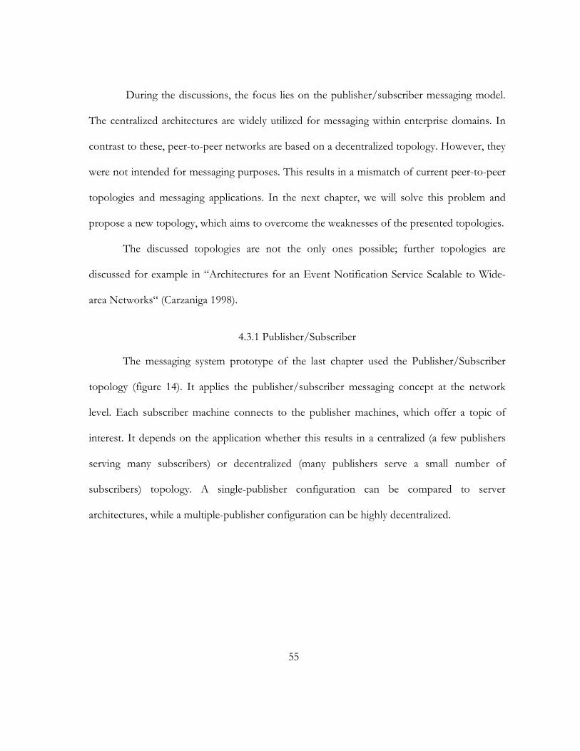
55
During the discussions, the focus lies on the publisher/subscriber messaging model.
The centralized architectures are widely utilized for messaging within enterprise domains. In
contrast to these, peer-to-peer networks are based on a decentralized topology. However, they
were not intended for messaging purposes. This results in a mismatch of current peer-to-peer
topologies and messaging applications. In the next chapter, we will solve this problem and
propose a new topology, which aims to overcome the weaknesses of the presented topologies.
The discussed topologies are not the only ones possible; further topologies are
discussed for example in “Architectures for an Event Notification Service Scalable to Wide-
area Networks“ (Carzaniga 1998).
4.3.1 Publisher/Subscriber
The messaging system prototype of the last chapter used the Publisher/Subscriber
topology (figure 14). It applies the publisher/subscriber messaging concept at the network
level. Each subscriber machine connects to the publisher machines, which offer a topic of
interest. It depends on the application whether this results in a centralized (a few publishers
serving many subscribers) or decentralized (many publishers serve a small number of
subscribers) topology. A single-publisher configuration can be compared to server
architectures, while a multiple-publisher configuration can be highly decentralized.
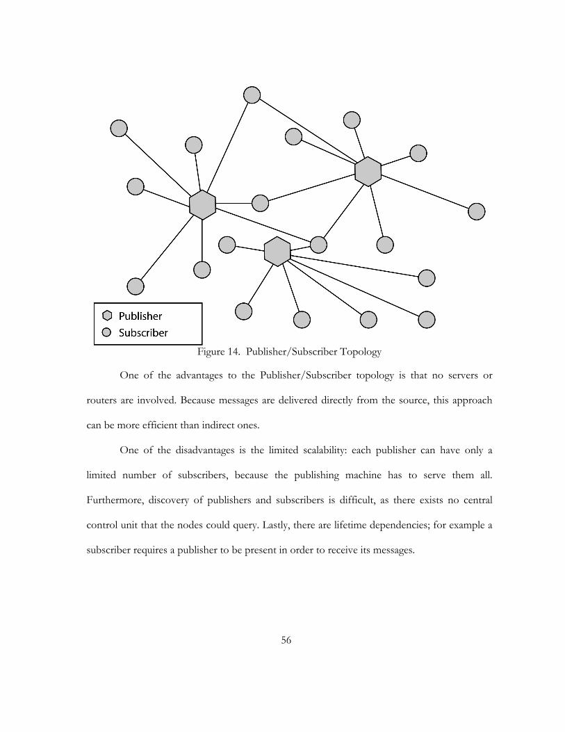
56
Figure 14. Publisher/Subscriber Topology
One of the advantages to the Publisher/Subscriber topology is that no servers or
routers are involved. Because messages are delivered directly from the source, this approach
can be more efficient than indirect ones.
One of the disadvantages is the limited scalability: each publisher can have only a
limited number of subscribers, because the publishing machine has to serve them all.
Furthermore, discovery of publishers and subscribers is difficult, as there exists no central
control unit that the nodes could query. Lastly, there are lifetime dependencies; for example a
subscriber requires a publisher to be present in order to receive its messages.
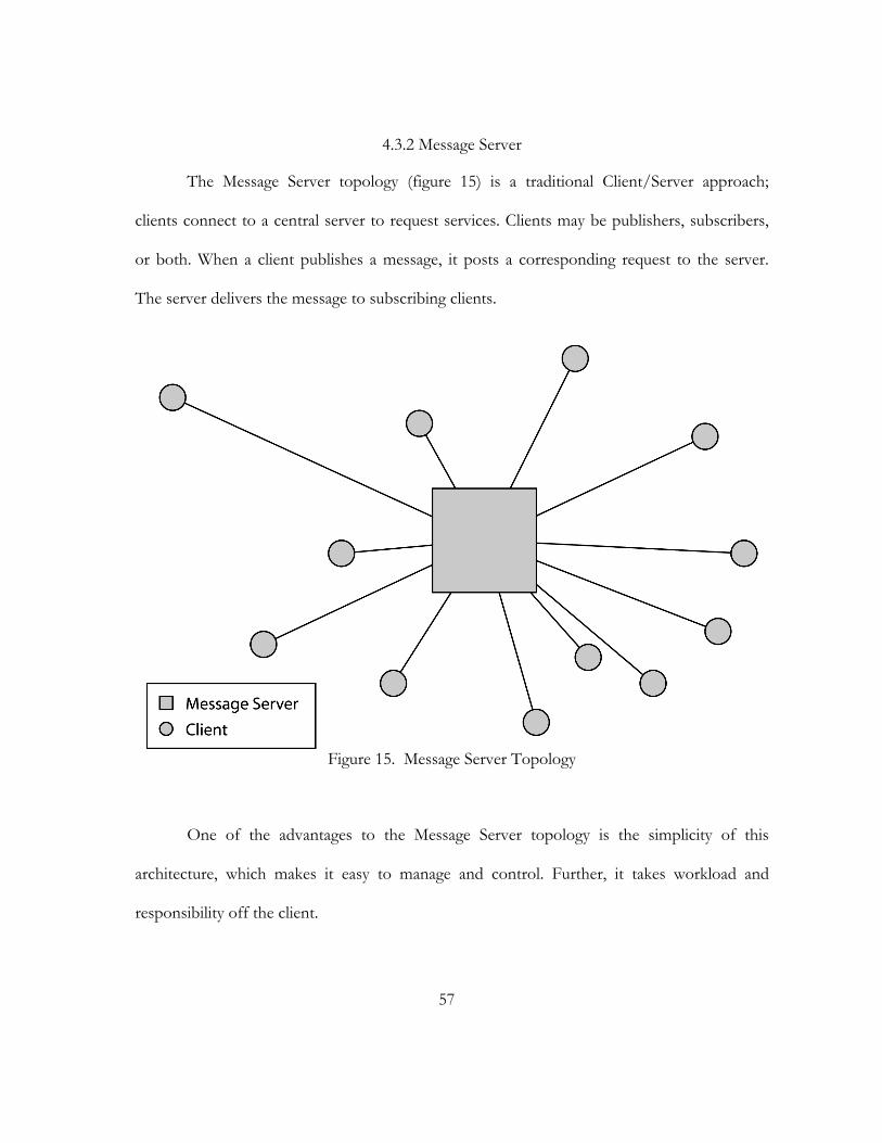
57
4.3.2 Message Server
The Message Server topology (figure 15) is a traditional Client/Server approach;
clients connect to a central server to request services. Clients may be publishers, subscribers,
or both. When a client publishes a message, it posts a corresponding request to the server.
The server delivers the message to subscribing clients.
Figure 15. Message Server Topology
One of the advantages to the Message Server topology is the simplicity of this
architecture, which makes it easy to manage and control. Further, it takes workload and
responsibility off the client.
58
One of the disadvantages is the single point of failure, as the whole system relies on a
fully functional server. In addition, a powerful server is required, depending on the expected
workload. Lastly, scalability is limited because this is a single machine approach.
4.3.3 Message Router
The Message Router topology (figure 16) addresses the problems of the Message
Server architecture. It is still a centralized approach because a router usually serves a big
number of clients. However, the routers are connected with each other and divide tasks
collaboratively.
Figure 16. Message Router Topology

59
One of the advantages to the Message Router topology is scalability: routers can be
added when the workload is getting too high for the existing routers. Like the Message Server
architecture, it takes workload and responsibility off the client. This architecture is failure
tolerant as other routers can take over work of non-functional routers. In addition, it allows a
more efficient communication than server-based approaches because routers can be placed
close to clients.
One of the disadvantages is that dedicated routers are needed. Further, maintaining
multiple routers requires a higher administrative effort.
4.3.4 Peer-to-Peer
The peer-to-peer topology (figure 17) is fully decentralized. Each network node is
considered a peer, which has one or more connection to other peers. Simple peer-to-peer
networks, like Gnutella (Gnutella 2000), forward messages to every peer. Recent approaches,
like Pastry (Rowstron and Druschel 2001), implement routing mechanisms to prevent message
flooding.
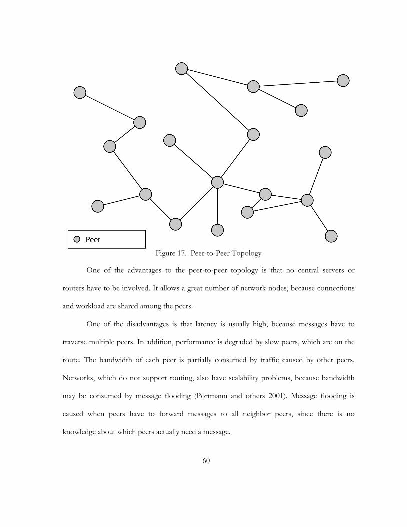
60
Figure 17. Peer-to-Peer Topology
One of the advantages to the peer-to-peer topology is that no central servers or
routers have to be involved. It allows a great number of network nodes, because connections
and workload are shared among the peers.
One of the disadvantages is that latency is usually high, because messages have to
traverse multiple peers. In addition, performance is degraded by slow peers, which are on the
route. The bandwidth of each peer is partially consumed by traffic caused by other peers.
Networks, which do not support routing, also have scalability problems, because bandwidth
may be consumed by message flooding (Portmann and others 2001). Message flooding is
caused when peers have to forward messages to all neighbor peers, since there is no
knowledge about which peers actually need a message.
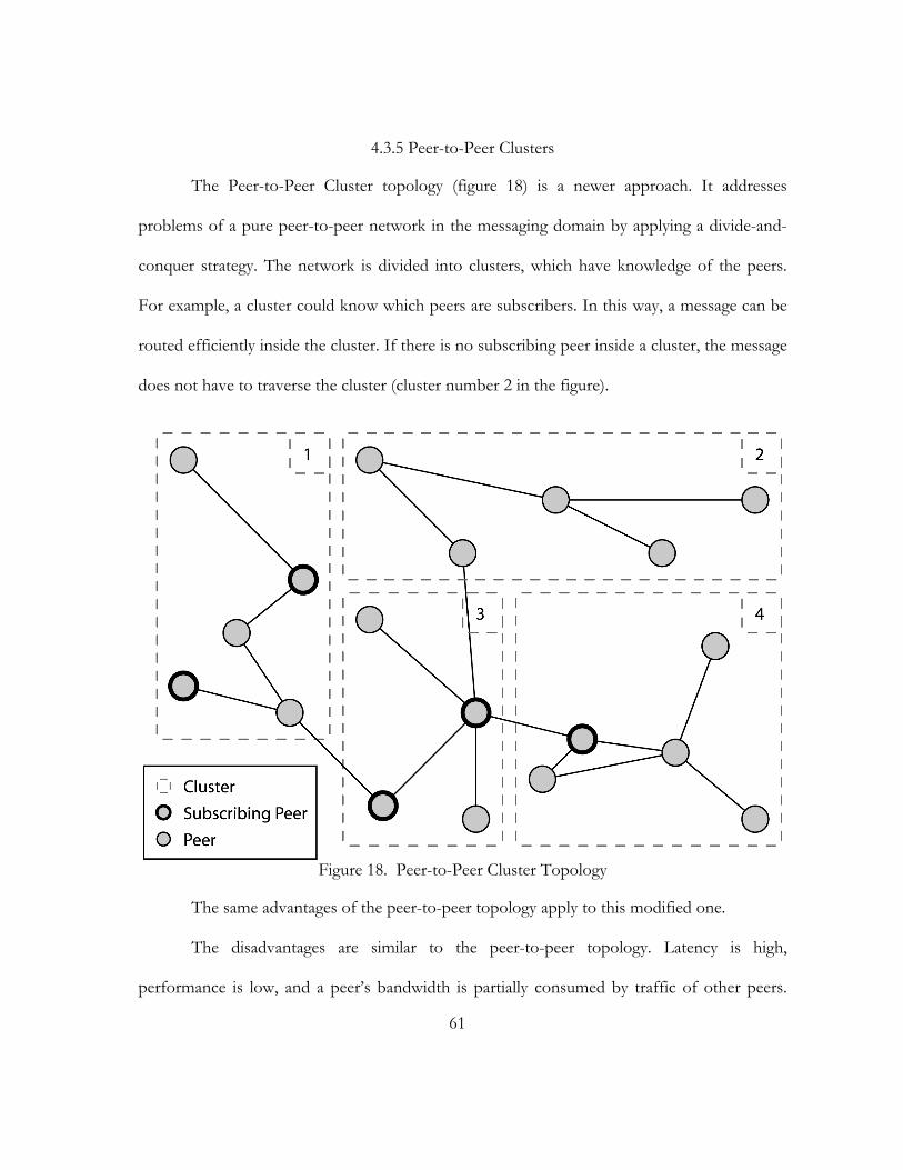
61
4.3.5 Peer-to-Peer Clusters
The Peer-to-Peer Cluster topology (figure 18) is a newer approach. It addresses
problems of a pure peer-to-peer network in the messaging domain by applying a divide-and-
conquer strategy. The network is divided into clusters, which have knowledge of the peers.
For example, a cluster could know which peers are subscribers. In this way, a message can be
routed efficiently inside the cluster. If there is no subscribing peer inside a cluster, the message
does not have to traverse the cluster (cluster number 2 in the figure).
Figure 18. Peer-to-Peer Cluster Topology
The same advantages of the peer-to-peer topology apply to this modified one.
The disadvantages are similar to the peer-to-peer topology. Latency is high,
performance is low, and a peer’s bandwidth is partially consumed by traffic of other peers.
62
However, clustering helps to improve these issues as unnecessary traffic and message flooding
can be largely avoided.
4.4. Summary
During this chapter, we analyzed network technologies, which were candidates for
solving scalability problems. IP multicasting is still impractical due to problems related to
control and manageability. Application layer multicasting overcomes some of these issues but
still lacks quality-of-service parameters, which are needed for messaging systems. We also
investigated several network topologies: Publisher/Subscriber, Message Server, Message
Router, Peer-to-Peer, and Peer-to-Peer Clusters. Each topology had advantages and
disadvantages, and none is an optimal choice for scalable peer-to-peer messaging. The next
chapter addresses this deficiency and proposes a solution based on a new topology.
63
CHAPTER 5
THE P2P MESSAGING SYSTEM AND
THE MULTI-RING TOPOLOGY
This chapter presents the P2P Messaging System and the novel multi-ring topology,
which is designed to meet requirements for high performance group communication in large-
scale peer-to-peer networks. In the previous chapter, we investigated multicasting techniques
and network topologies and pointed out their disadvantages in the peer-to-peer messaging
domain. We showed that IP multicasting has several serious weaknesses, making it unusable
for our purpose. Application layer multicasting lacks Quality-of-Service parameters, which are
needed by messaging systems. The solution presented in section 5.2.1 is based on a topic-
centric application layer multicasting, which takes care of Quality-of-Service parameters
directly. Building overlay networks for each topic makes the message delivery independent
from the peer-to-peer network and overcomes its constrains. The previous chapter illustrated
the mismatch of messaging topologies and peer-to-peer networks: current messaging
topologies are centralized, and decentralized peer-to-peer topologies are not efficient for
messaging applications. Now, we address this mismatch with the multi-ring topology. It aims
to combine the robustness and manageability of ring topologies (section 5.2.2.1) and the
scalability of tree topologies (section 5.2.2.2). The basic concepts, based on multiple overlay
networks, and its dynamics are introduced. In the end of this chapter, the prototype of the
P2P Messaging System and its models will be introduced.
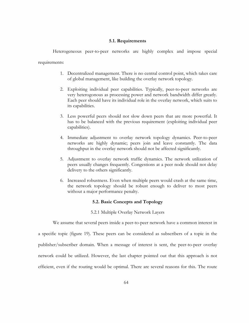
64
5.1. Requirements
Heterogeneous peer-to-peer networks are highly complex and impose special
requirements:
1. Decentralized management. There is no central control point, which takes care of global management, like building the overlay network topology.
2. Exploiting individual peer capabilities. Typically, peer-to-peer networks are very heterogonous as processing power and network bandwidth differ greatly. Each peer should have its individual role in the overlay network, which suits to its capabilities.
3. Less powerful peers should not slow down peers that are more powerful. It has to be balanced with the previous requirement (exploiting individual peer capabilities).
4. Immediate adjustment to overlay network topology dynamics. Peer-to-peer networks are highly dynamic; peers join and leave constantly. The data throughput in the overlay network should not be affected significantly.
5. Adjustment to overlay network traffic dynamics. The network utilization of peers usually changes frequently. Congestions at a peer node should not delay delivery to the others significantly.
6. Increased robustness. Even when multiple peers would crash at the same time, the network topology should be robust enough to deliver to most peers without a major performance penalty.
5.2. Basic Concepts and Topology
5.2.1 Multiple Overlay Network Layers
We assume that several peers inside a peer-to-peer network have a common interest in
a specific topic (figure 19). These peers can be considered as subscribers of a topic in the
publisher/subscriber domain. When a message of interest is sent, the peer-to-peer overlay
network could be utilized. However, the last chapter pointed out that this approach is not
efficient, even if the routing would be optimal. There are several reasons for this. The route
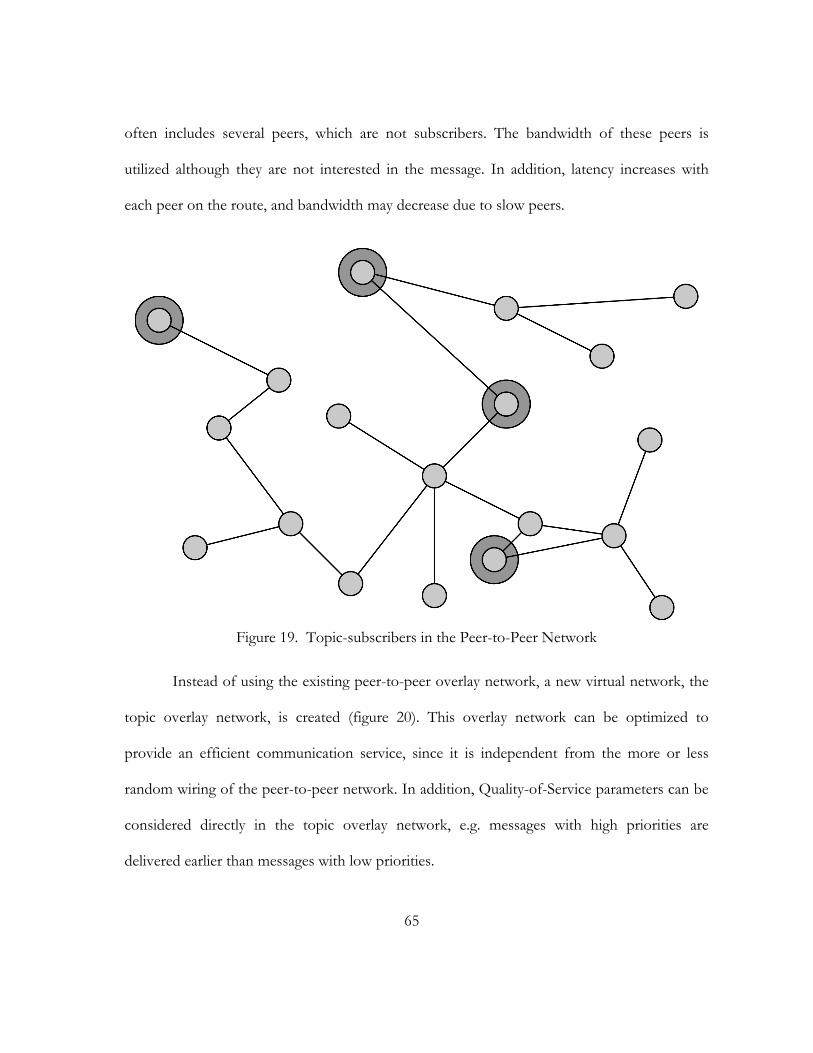
65
often includes several peers, which are not subscribers. The bandwidth of these peers is
utilized although they are not interested in the message. In addition, latency increases with
each peer on the route, and bandwidth may decrease due to slow peers.
Figure 19. Topic-subscribers in the Peer-to-Peer Network
Instead of using the existing peer-to-peer overlay network, a new virtual network, the
topic overlay network, is created (figure 20). This overlay network can be optimized to
provide an efficient communication service, since it is independent from the more or less
random wiring of the peer-to-peer network. In addition, Quality-of-Service parameters can be
considered directly in the topic overlay network, e.g. messages with high priorities are
delivered earlier than messages with low priorities.
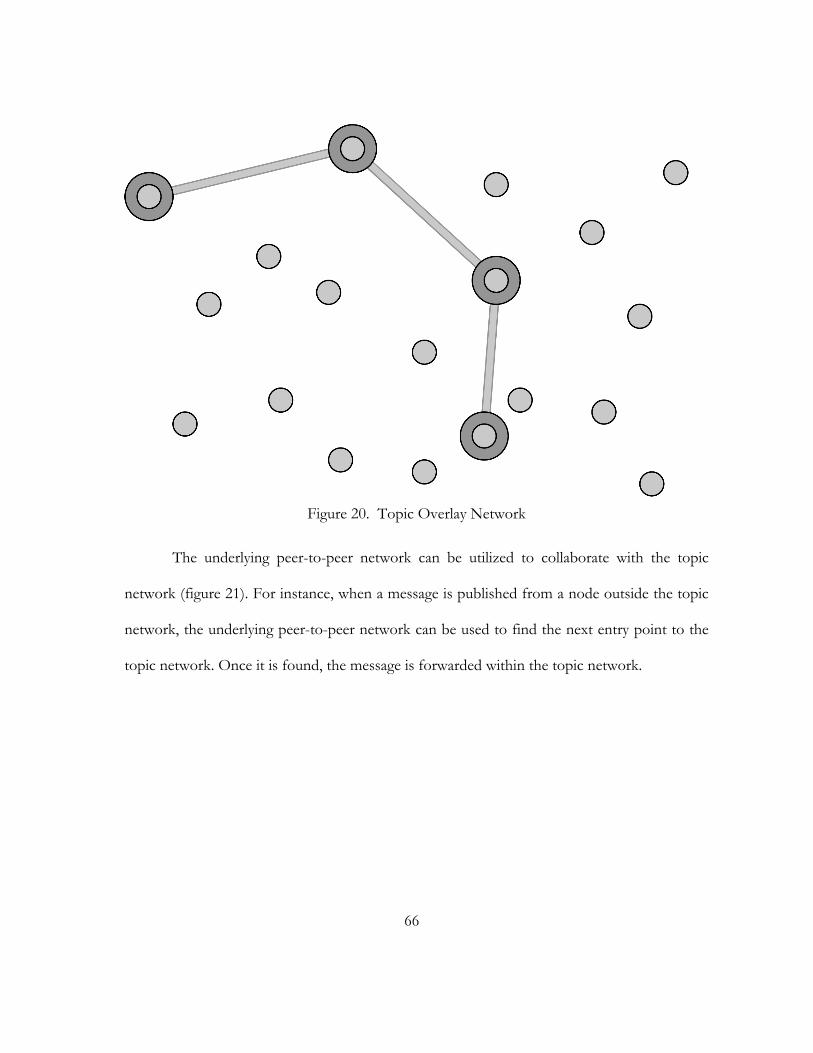
66
Figure 20. Topic Overlay Network
The underlying peer-to-peer network can be utilized to collaborate with the topic
network (figure 21). For instance, when a message is published from a node outside the topic
network, the underlying peer-to-peer network can be used to find the next entry point to the
topic network. Once it is found, the message is forwarded within the topic network.
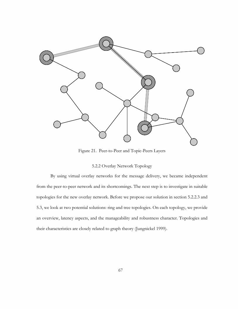
67
Figure 21. Peer-to-Peer and Topic-Peers Layers
5.2.2 Overlay Network Topology
By using virtual overlay networks for the message delivery, we became independent
from the peer-to-peer network and its shortcomings. The next step is to investigate in suitable
topologies for the new overlay network. Before we propose our solution in section 5.2.2.3 and
5.3, we look at two potential solutions: ring and tree topologies. On each topology, we provide
an overview, latency aspects, and the manageability and robustness character. Topologies and
their characteristics are closely related to graph theory (Jungnickel 1999).
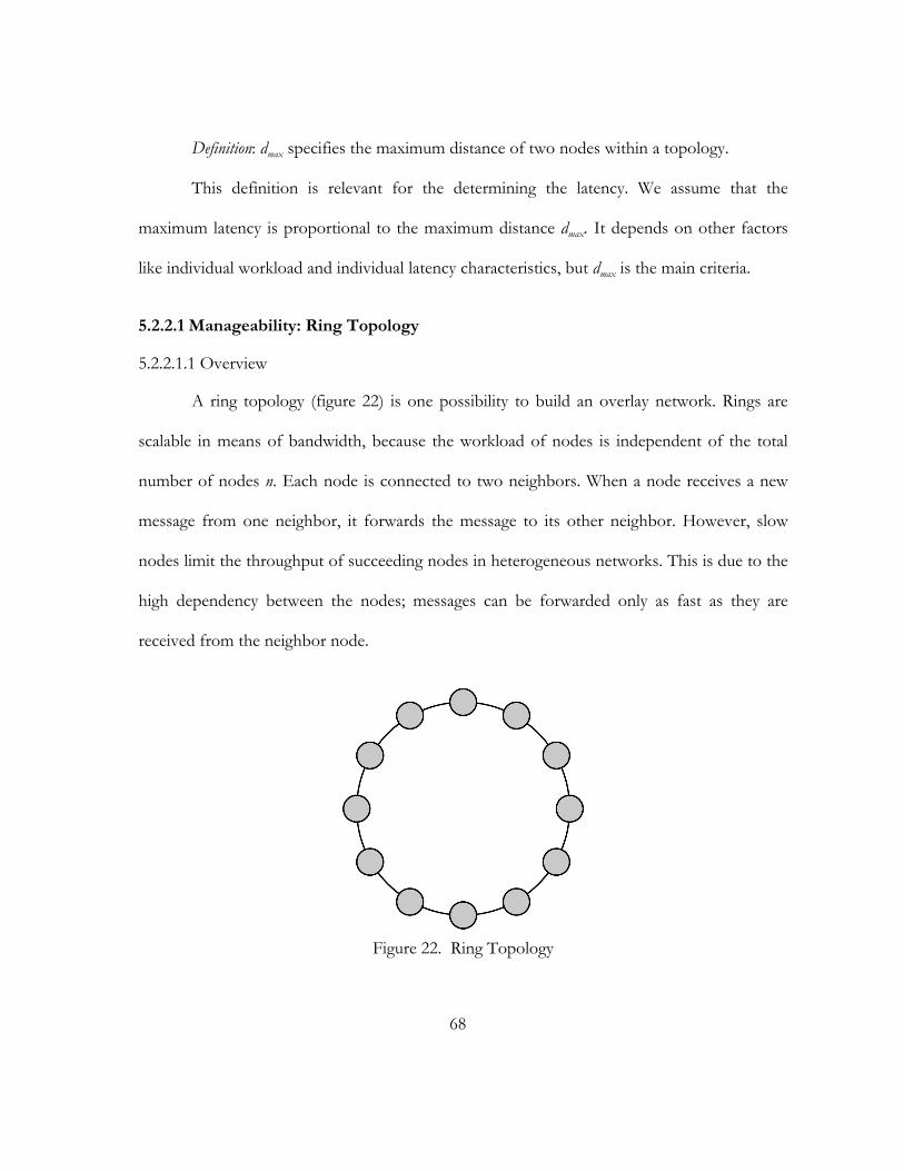
68
Definition: dmax specifies the maximum distance of two nodes within a topology.
This definition is relevant for the determining the latency. We assume that the
maximum latency is proportional to the maximum distance dmax. It depends on other factors
like individual workload and individual latency characteristics, but dmax is the main criteria.
5.2.2.1 Manageability: Ring Topology
5.2.2.1.1 Overview
A ring topology (figure 22) is one possibility to build an overlay network. Rings are
scalable in means of bandwidth, because the workload of nodes is independent of the total
number of nodes n. Each node is connected to two neighbors. When a node receives a new
message from one neighbor, it forwards the message to its other neighbor. However, slow
nodes limit the throughput of succeeding nodes in heterogeneous networks. This is due to the
high dependency between the nodes; messages can be forwarded only as fast as they are
received from the neighbor node.
Figure 22. Ring Topology
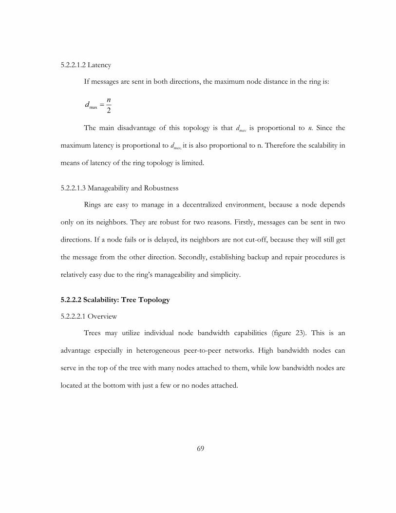
69
5.2.2.1.2 Latency
If messages are sent in both directions, the maximum node distance in the ring is:
2maxnd =
The main disadvantage of this topology is that dmax is proportional to n. Since the
maximum latency is proportional to dmax, it is also proportional to n. Therefore the scalability in
means of latency of the ring topology is limited.
5.2.2.1.3 Manageability and Robustness
Rings are easy to manage in a decentralized environment, because a node depends
only on its neighbors. They are robust for two reasons. Firstly, messages can be sent in two
directions. If a node fails or is delayed, its neighbors are not cut-off, because they will still get
the message from the other direction. Secondly, establishing backup and repair procedures is
relatively easy due to the ring’s manageability and simplicity.
5.2.2.2 Scalability: Tree Topology
5.2.2.2.1 Overview
Trees may utilize individual node bandwidth capabilities (figure 23). This is an
advantage especially in heterogeneous peer-to-peer networks. High bandwidth nodes can
serve in the top of the tree with many nodes attached to them, while low bandwidth nodes are
located at the bottom with just a few or no nodes attached.

70
Figure 23. Tree topology: can utilize individual node bandwidth capabilities
5.2.2.2.2 Latency
We assume a balanced tree and that each node can have k child nodes. The maximum
number of nodes nh of a balanced tree with height h is:
( )
)3(11
)1()2(11
)2(...
)1(...
1
1
1321
210
−−
=
−−=−
+++=⋅
++++=
+
+
+
kkn
kknkkkknkkkkkn
h
h
hh
hh
hh
The height h of a balanced tree with n nodes can be approximated:
( )( )
( )( )( )( ) 111log
11log111
1111
1
1
1
−+−=+−=+
+−=
−=−−−
=
+
+
+
knhknh
knkkkn
kkn
hk
hk
hh
hh
h
h
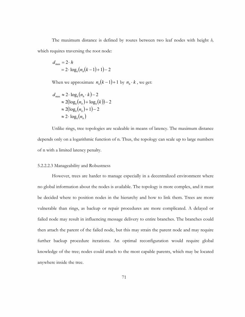
71
The maximum distance is defined by routes between two leaf nodes with height h,
which requires traversing the root node:
( )( ) 211log22max
−+−⋅=⋅=
knhd
hk
When we approximate ( ) 11 +−knh by knh ⋅ , we get:
( )( ) ( )( )( )( )( )hk
hk
khk
hk
nn
knknd
log221log2
2loglog22log2max
⋅≈−+≈
−+≈−⋅⋅≈
Unlike rings, tree topologies are scaleable in means of latency. The maximum distance
depends only on a logarithmic function of n. Thus, the topology can scale up to large numbers
of n with a limited latency penalty.
5.2.2.2.3 Manageability and Robustness
However, trees are harder to manage especially in a decentralized environment where
no global information about the nodes is available. The topology is more complex, and it must
be decided where to position nodes in the hierarchy and how to link them. Trees are more
vulnerable than rings, as backup or repair procedures are more complicated. A delayed or
failed node may result in influencing message delivery to entire branches. The branches could
then attach the parent of the failed node, but this may strain the parent node and may require
further backup procedure iterations. An optimal reconfiguration would require global
knowledge of the tree; nodes could attach to the most capable parents, which may be located
anywhere inside the tree.
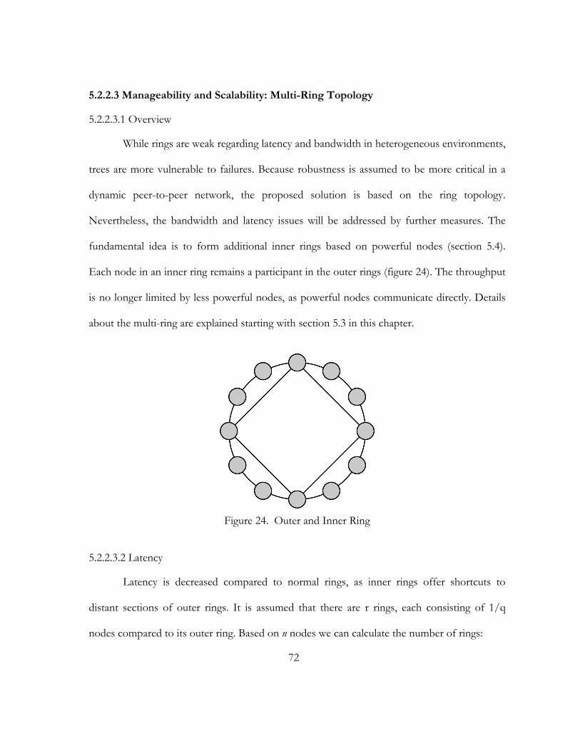
72
5.2.2.3 Manageability and Scalability: Multi-Ring Topology
5.2.2.3.1 Overview
While rings are weak regarding latency and bandwidth in heterogeneous environments,
trees are more vulnerable to failures. Because robustness is assumed to be more critical in a
dynamic peer-to-peer network, the proposed solution is based on the ring topology.
Nevertheless, the bandwidth and latency issues will be addressed by further measures. The
fundamental idea is to form additional inner rings based on powerful nodes (section 5.4).
Each node in an inner ring remains a participant in the outer rings (figure 24). The throughput
is no longer limited by less powerful nodes, as powerful nodes communicate directly. Details
about the multi-ring are explained starting with section 5.3 in this chapter.
Figure 24. Outer and Inner Ring
5.2.2.3.2 Latency
Latency is decreased compared to normal rings, as inner rings offer shortcuts to
distant sections of outer rings. It is assumed that there are r rings, each consisting of 1/q
nodes compared to its outer ring. Based on n nodes we can calculate the number of rings:
73
( )nr qlog=
We assume that the distance between nodes involved in an inner ring is balanced over
each ring. The number of steps in order to reach a node involved in an additional ring is q/2
at maximum. The longest possible route is described between two nodes located at opposite
sides in the outer ring. It requires passing each ring twice.
( )nqdrqd
rqd
qlog
22
max
max
max
⋅=⋅=
⋅=
The scalability character of the proposed multi-ring topology is similar to the one of
the tree topology. The maximum distance depends only on a logarithmic function of n. Thus,
the topology can scale up to large numbers of n with a limited latency penalty.
5.2.2.3.3 Manageability and Robustness
Setting up multiple rings requires more steps to be taken than the setup for a single
ring. It has to be decided when to set up and remove inner rings, and which nodes participate.
Further, the distance between nodes participating in an inner ring should be balanced to keep
the maximum distance between nodes low. Despite the additional measures, it is more
manageable than a tree, because these steps do not require global knowledge. The robustness
of rings is further improved by inner rings, which increase the level of connectivity.
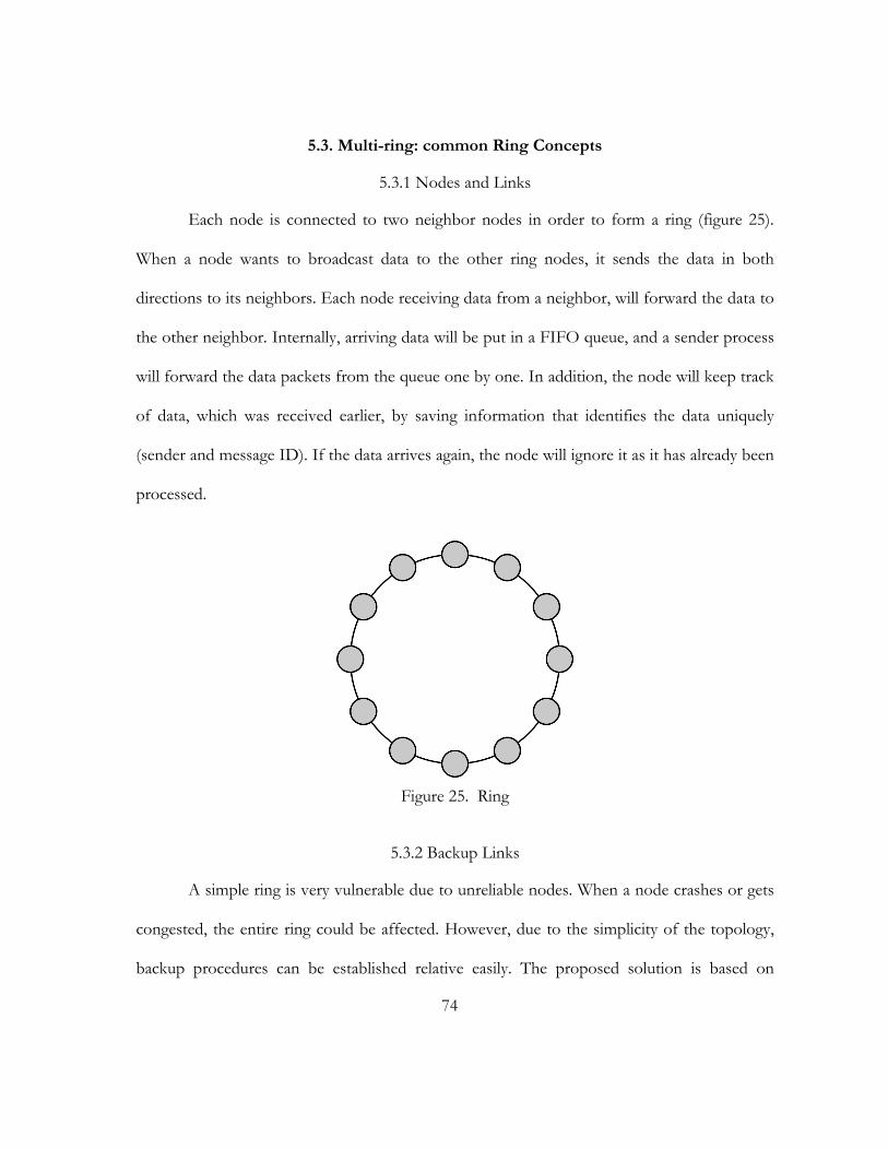
74
5.3. Multi-ring: common Ring Concepts
5.3.1 Nodes and Links
Each node is connected to two neighbor nodes in order to form a ring (figure 25).
When a node wants to broadcast data to the other ring nodes, it sends the data in both
directions to its neighbors. Each node receiving data from a neighbor, will forward the data to
the other neighbor. Internally, arriving data will be put in a FIFO queue, and a sender process
will forward the data packets from the queue one by one. In addition, the node will keep track
of data, which was received earlier, by saving information that identifies the data uniquely
(sender and message ID). If the data arrives again, the node will ignore it as it has already been
processed.
Figure 25. Ring
5.3.2 Backup Links
A simple ring is very vulnerable due to unreliable nodes. When a node crashes or gets
congested, the entire ring could be affected. However, due to the simplicity of the topology,
backup procedures can be established relative easily. The proposed solution is based on
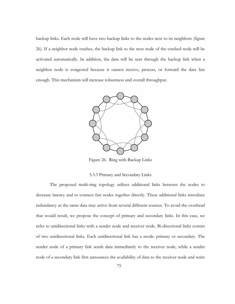
75
backup links. Each node will have two backup links to the nodes next to its neighbors (figure
26). If a neighbor node crashes, the backup link to the next node of the crashed node will be
activated automatically. In addition, the data will be sent through the backup link when a
neighbor node is congested because it cannot receive, process, or forward the data fast
enough. This mechanism will increase robustness and overall throughput.
Figure 26. Ring with Backup Links
5.3.3 Primary and Secondary Links
The proposed multi-ring topology utilizes additional links between the nodes to
decrease latency and to connect fast nodes together directly. These additional links introduce
redundancy as the same data may arrive from several different sources. To avoid the overhead
that would result, we propose the concept of primary and secondary links. In this case, we
refer to unidirectional links with a sender node and receiver node. Bi-directional links consist
of two unidirectional links. Each unidirectional link has a mode: primary or secondary. The
sender node of a primary link sends data immediately to the receiver node, while a sender
node of a secondary link first announces the availability of data to the receiver node and waits
76
for the answers whether the data should be sent. This concept considers that there is a specific
route, which is preferred over others because it is faster. This route typically consists of
primary links, while other routes include secondary links.
5.3.3.1 Determining the Mode
The decision, whether a unidirectional link is primary or secondary, is determined dynamically
by the system and is adjusted when needed. In the beginning, all links are primary. However,
due to redundant routes, nodes receive data more than once. They change the mode to
secondary if a link delivers obsolete data frequently. The receiver decides when to change the
mode by keeping track of the last y data packages. The condition a primary link has to fulfill is
that at least x out of the last y packages have to contain data, which was not previously
delivered to the link. If the link does not fulfill this condition, its mode is switched to
secondary. Secondary links, which fulfill the condition, are switched to primary. It depends on
the values of x and y whether the mode switches fast or not. Since switching implies only little
overhead, we propose low values to adjust to new situations quickly, like four for x and six for
y. To switch modes, the receiver node sends command messages containing the new mode to
the sender.
5.4. Multi-Ring: Inner Rings
5.4.1 Identifying Nodes for Inner Rings
5.4.1.1 Determining Bandwidth
The first step in order to establish inner rings is to identify the nodes that will
participate. Nodes, which are part of multiple rings, must provide a higher workload. In
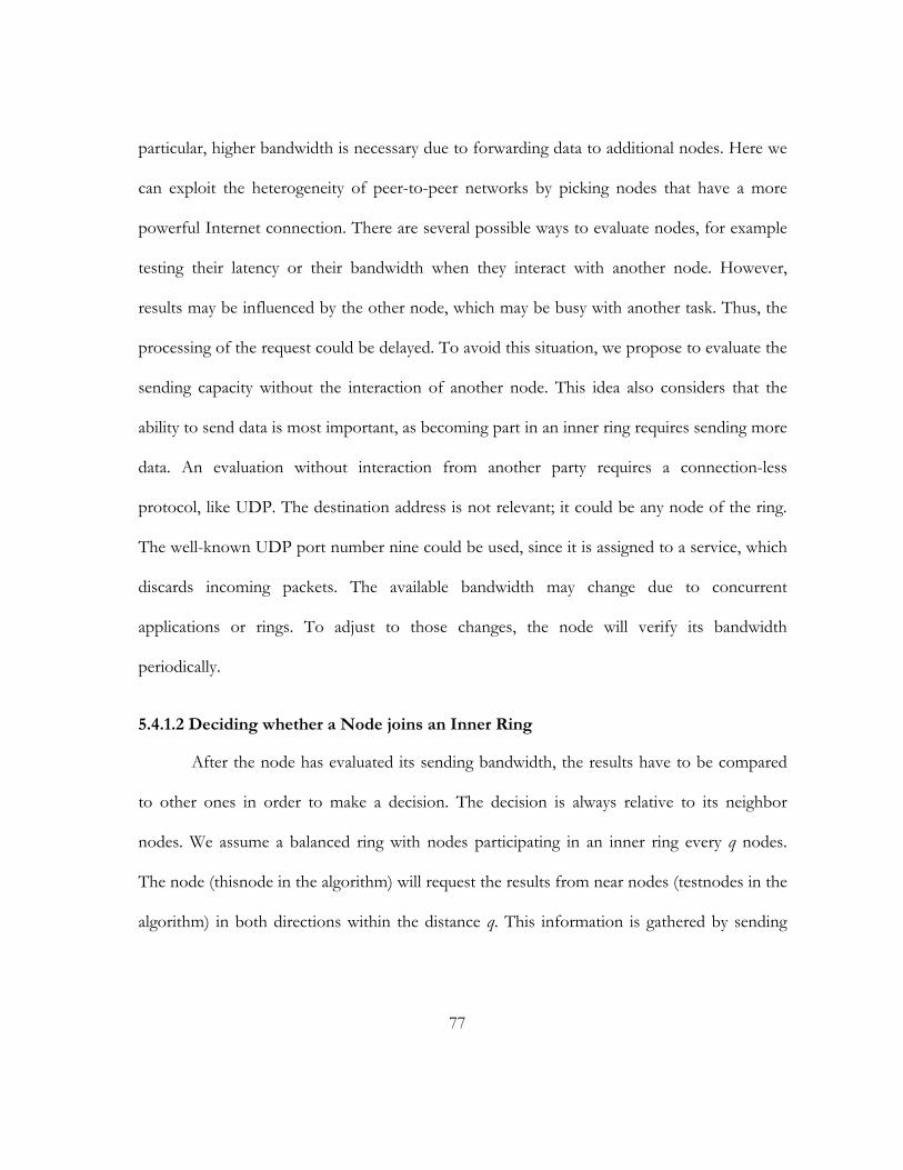
77
particular, higher bandwidth is necessary due to forwarding data to additional nodes. Here we
can exploit the heterogeneity of peer-to-peer networks by picking nodes that have a more
powerful Internet connection. There are several possible ways to evaluate nodes, for example
testing their latency or their bandwidth when they interact with another node. However,
results may be influenced by the other node, which may be busy with another task. Thus, the
processing of the request could be delayed. To avoid this situation, we propose to evaluate the
sending capacity without the interaction of another node. This idea also considers that the
ability to send data is most important, as becoming part in an inner ring requires sending more
data. An evaluation without interaction from another party requires a connection-less
protocol, like UDP. The destination address is not relevant; it could be any node of the ring.
The well-known UDP port number nine could be used, since it is assigned to a service, which
discards incoming packets. The available bandwidth may change due to concurrent
applications or rings. To adjust to those changes, the node will verify its bandwidth
periodically.
5.4.1.2 Deciding whether a Node joins an Inner Ring
After the node has evaluated its sending bandwidth, the results have to be compared
to other ones in order to make a decision. The decision is always relative to its neighbor
nodes. We assume a balanced ring with nodes participating in an inner ring every q nodes.
The node (thisnode in the algorithm) will request the results from near nodes (testnodes in the
algorithm) in both directions within the distance q. This information is gathered by sending

78
query system messages, which will be answered by the nodes with response system messages.
Based on this information, the decision will be made with the following algorithm:
(01) testnodes=neighbors of thisnode with maximum distance q
(02) ringnodes=all node in testnodes, which are not involved in inner rings
(03) if(thisnode.bandwidth == max(ringnodes.bandwidth))
(04) {
(05) innerleft=next inner ring node of testnodes to the left
(06) innerright=next inner ring node of testnodes to the right
(07) addNode=false
(08) if(innerleft not exists OR innerright not exists) {addNode=true}
(09) else if(distance(innerleft,innerright) > q) {addNode=true}
(10) else{
(11) innernodes=inner ring neighbors of innerleft with maximum distance q
(12) if(thisnode.bandwidth > min(innernodes.bandwidth)) {addNode=true}
(13) }
(14) if(addNode==true) {add thisnode to inner ring}
(15) }
5.4.1.3 Verifying Nodes in Inner Rings
The membership of inner ring nodes has to be verified frequently. The arrival of more
capable nodes may lead to the abandon of less capable ones. In addition, the available
bandwidth may change due to concurrent network traffic. The decision is based on a
bandwidth comparison with the neighbor ring nodes. The following algorithm is used:
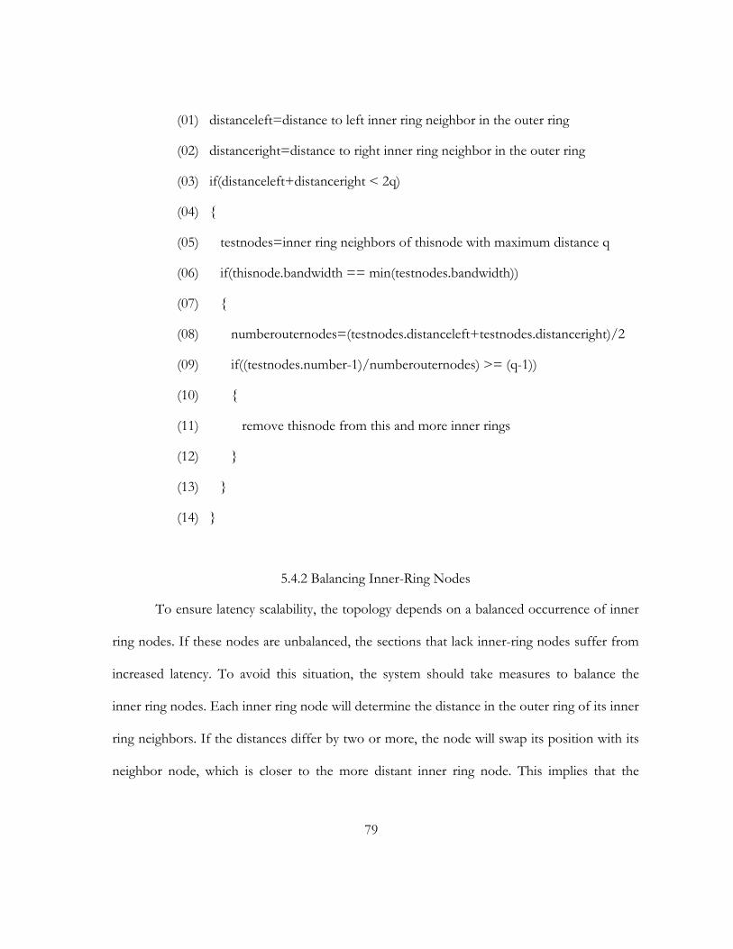
79
(01) distanceleft=distance to left inner ring neighbor in the outer ring
(02) distanceright=distance to right inner ring neighbor in the outer ring
(03) if(distanceleft+distanceright < 2q)
(04) {
(05) testnodes=inner ring neighbors of thisnode with maximum distance q
(06) if(thisnode.bandwidth == min(testnodes.bandwidth))
(07) {
(08) numberouternodes=(testnodes.distanceleft+testnodes.distanceright)/2
(09) if((testnodes.number-1)/numberouternodes) >= (q-1))
(10) {
(11) remove thisnode from this and more inner rings
(12) }
(13) }
(14) }
5.4.2 Balancing Inner-Ring Nodes
To ensure latency scalability, the topology depends on a balanced occurrence of inner
ring nodes. If these nodes are unbalanced, the sections that lack inner-ring nodes suffer from
increased latency. To avoid this situation, the system should take measures to balance the
inner ring nodes. Each inner ring node will determine the distance in the outer ring of its inner
ring neighbors. If the distances differ by two or more, the node will swap its position with its
neighbor node, which is closer to the more distant inner ring node. This implies that the
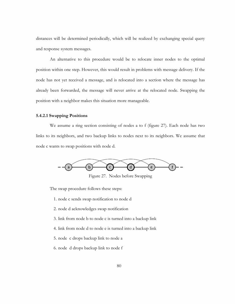
80
distances will be determined periodically, which will be realized by exchanging special query
and response system messages.
An alternative to this procedure would be to relocate inner nodes to the optimal
position within one step. However, this would result in problems with message delivery. If the
node has not yet received a message, and is relocated into a section where the message has
already been forwarded, the message will never arrive at the relocated node. Swapping the
position with a neighbor makes this situation more manageable.
5.4.2.1 Swapping Positions
We assume a ring section consisting of nodes a to f (figure 27). Each node has two
links to its neighbors, and two backup links to nodes next to its neighbors. We assume that
node c wants to swap positions with node d.
Figure 27. Nodes before Swapping
The swap procedure follows these steps:
1. node c sends swap notification to node d
2. node d acknowledges swap notification
3. link from node b to node c is turned into a backup link
4. link from node d to node e is turned into a backup link
5. node c drops backup link to node a
6. node d drops backup link to node f
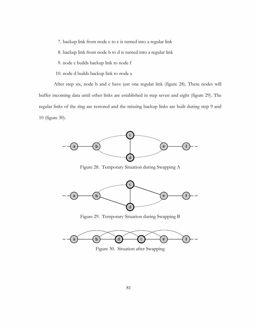
81
7. backup link from node c to e is turned into a regular link
8. backup link from node b to d is turned into a regular link
9. node c builds backup link to node f
10. node d builds backup link to node a
After step six, node b and e have just one regular link (figure 28). These nodes will
buffer incoming data until other links are established in step seven and eight (figure 29). The
regular links of the ring are restored and the missing backup links are built during step 9 and
10 (figure 30).
Figure 28. Temporary Situation during Swapping A
Figure 29. Temporary Situation during Swapping B
Figure 30. Situation after Swapping
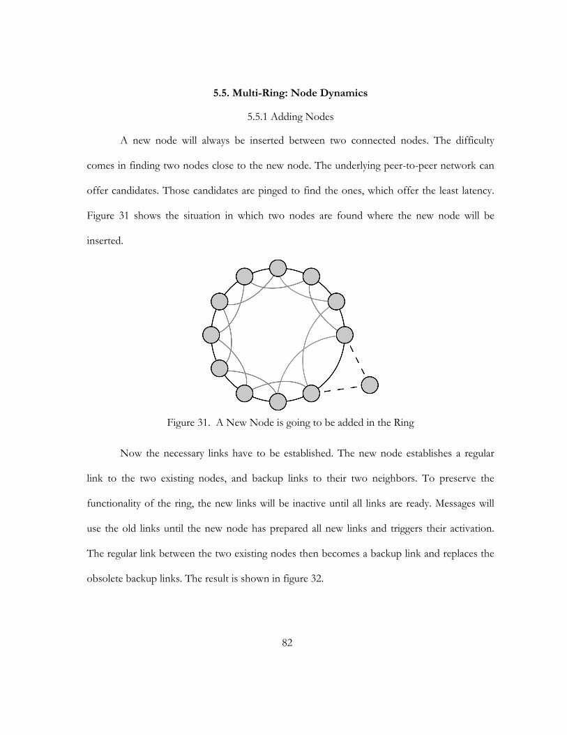
82
5.5. Multi-Ring: Node Dynamics
5.5.1 Adding Nodes
A new node will always be inserted between two connected nodes. The difficulty
comes in finding two nodes close to the new node. The underlying peer-to-peer network can
offer candidates. Those candidates are pinged to find the ones, which offer the least latency.
Figure 31 shows the situation in which two nodes are found where the new node will be
inserted.
Figure 31. A New Node is going to be added in the Ring
Now the necessary links have to be established. The new node establishes a regular
link to the two existing nodes, and backup links to their two neighbors. To preserve the
functionality of the ring, the new links will be inactive until all links are ready. Messages will
use the old links until the new node has prepared all new links and triggers their activation.
The regular link between the two existing nodes then becomes a backup link and replaces the
obsolete backup links. The result is shown in figure 32.
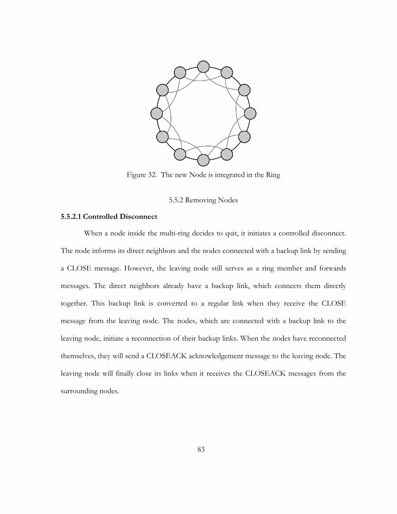
83
Figure 32. The new Node is integrated in the Ring
5.5.2 Removing Nodes
5.5.2.1 Controlled Disconnect
When a node inside the multi-ring decides to quit, it initiates a controlled disconnect.
The node informs its direct neighbors and the nodes connected with a backup link by sending
a CLOSE message. However, the leaving node still serves as a ring member and forwards
messages. The direct neighbors already have a backup link, which connects them directly
together. This backup link is converted to a regular link when they receive the CLOSE
message from the leaving node. The nodes, which are connected with a backup link to the
leaving node, initiate a reconnection of their backup links. When the nodes have reconnected
themselves, they will send a CLOSEACK acknowledgement message to the leaving node. The
leaving node will finally close its links when it receives the CLOSEACK messages from the
surrounding nodes.
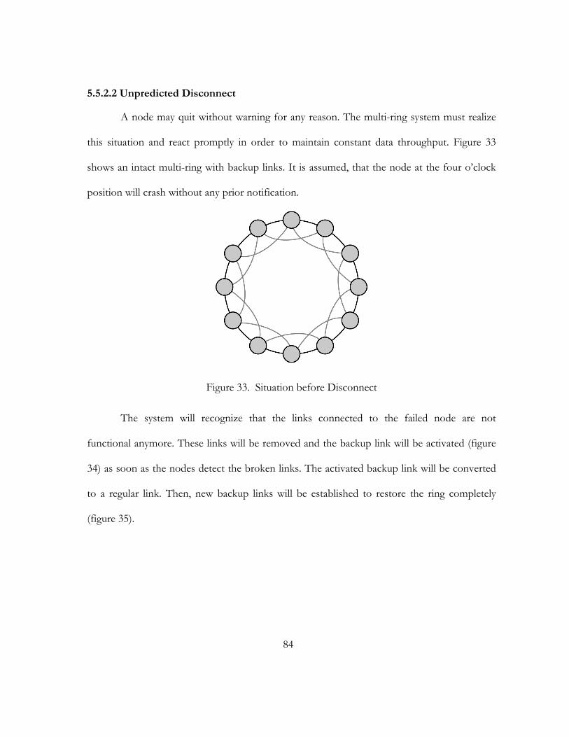
84
5.5.2.2 Unpredicted Disconnect
A node may quit without warning for any reason. The multi-ring system must realize
this situation and react promptly in order to maintain constant data throughput. Figure 33
shows an intact multi-ring with backup links. It is assumed, that the node at the four o’clock
position will crash without any prior notification.
Figure 33. Situation before Disconnect
The system will recognize that the links connected to the failed node are not
functional anymore. These links will be removed and the backup link will be activated (figure
34) as soon as the nodes detect the broken links. The activated backup link will be converted
to a regular link. Then, new backup links will be established to restore the ring completely
(figure 35).
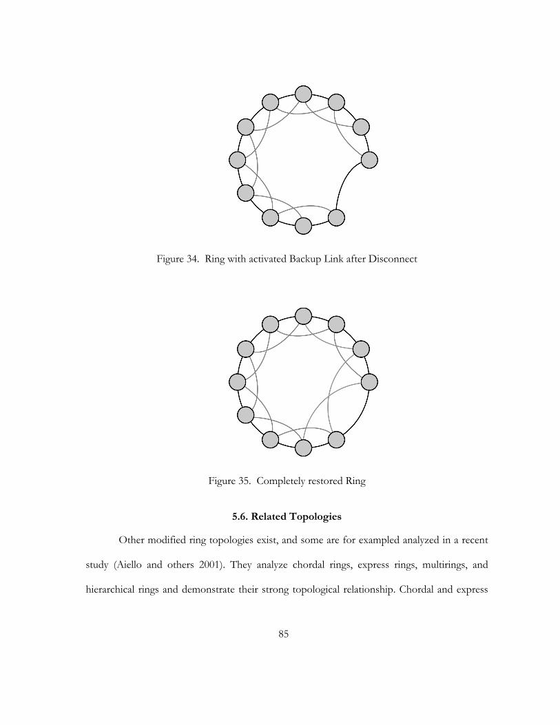
85
Figure 34. Ring with activated Backup Link after Disconnect
Figure 35. Completely restored Ring
5.6. Related Topologies
Other modified ring topologies exist, and some are for exampled analyzed in a recent
study (Aiello and others 2001). They analyze chordal rings, express rings, multirings, and
hierarchical rings and demonstrate their strong topological relationship. Chordal and express
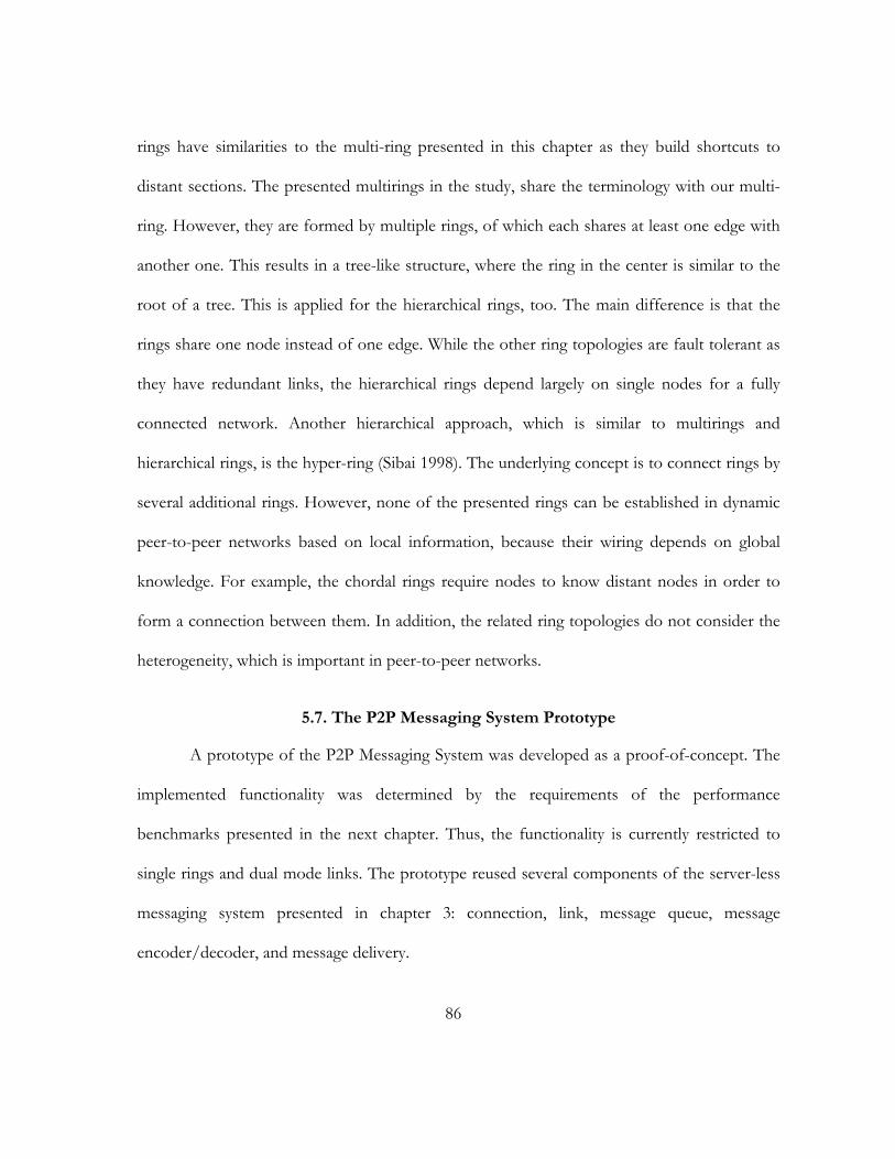
86
rings have similarities to the multi-ring presented in this chapter as they build shortcuts to
distant sections. The presented multirings in the study, share the terminology with our multi-
ring. However, they are formed by multiple rings, of which each shares at least one edge with
another one. This results in a tree-like structure, where the ring in the center is similar to the
root of a tree. This is applied for the hierarchical rings, too. The main difference is that the
rings share one node instead of one edge. While the other ring topologies are fault tolerant as
they have redundant links, the hierarchical rings depend largely on single nodes for a fully
connected network. Another hierarchical approach, which is similar to multirings and
hierarchical rings, is the hyper-ring (Sibai 1998). The underlying concept is to connect rings by
several additional rings. However, none of the presented rings can be established in dynamic
peer-to-peer networks based on local information, because their wiring depends on global
knowledge. For example, the chordal rings require nodes to know distant nodes in order to
form a connection between them. In addition, the related ring topologies do not consider the
heterogeneity, which is important in peer-to-peer networks.
5.7. The P2P Messaging System Prototype
A prototype of the P2P Messaging System was developed as a proof-of-concept. The
implemented functionality was determined by the requirements of the performance
benchmarks presented in the next chapter. Thus, the functionality is currently restricted to
single rings and dual mode links. The prototype reused several components of the server-less
messaging system presented in chapter 3: connection, link, message queue, message
encoder/decoder, and message delivery.
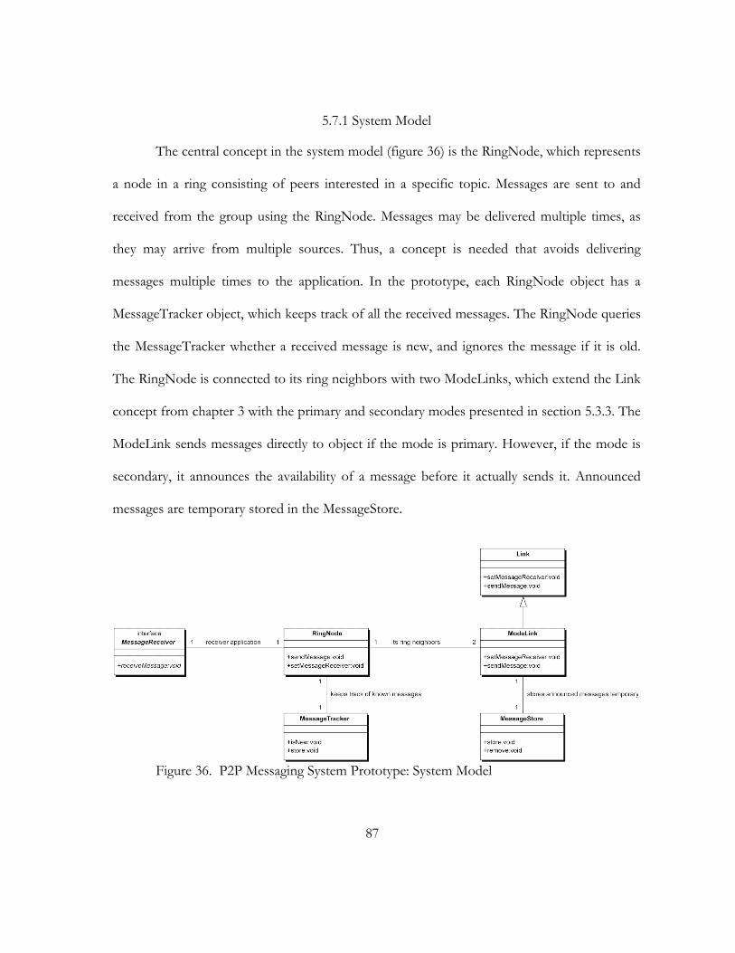
87
5.7.1 System Model
The central concept in the system model (figure 36) is the RingNode, which represents
a node in a ring consisting of peers interested in a specific topic. Messages are sent to and
received from the group using the RingNode. Messages may be delivered multiple times, as
they may arrive from multiple sources. Thus, a concept is needed that avoids delivering
messages multiple times to the application. In the prototype, each RingNode object has a
MessageTracker object, which keeps track of all the received messages. The RingNode queries
the MessageTracker whether a received message is new, and ignores the message if it is old.
The RingNode is connected to its ring neighbors with two ModeLinks, which extend the Link
concept from chapter 3 with the primary and secondary modes presented in section 5.3.3. The
ModeLink sends messages directly to object if the mode is primary. However, if the mode is
secondary, it announces the availability of a message before it actually sends it. Announced
messages are temporary stored in the MessageStore.
Figure 36. P2P Messaging System Prototype: System Model

88
5.7.2 Dual Mode Links
Secondary links require additional steps to be taken by the ModeLink. Messages are
announced by sending a corresponding announce message containing the message ID. In
addition, the ModeLink stores the message in the MessageStore temporary. The ModeLink on
the other communication side asks the RingNode associated with it whether a message with
the ID contained in the announce message was received before. Then, the second ModeLink
responds with a request message in case the message is new or with a reject message in case
the message is old. The first ModeLink receives the response message, removes the actual
message from the MessageStore, and, depending on response, sends or drops the message.
As explained in the last paragraph, two connected ModeLinks communicate with
special command messages in order to implement the dual mode link functionality. The
following pseudo-code illustrates the processing of received command messages:
(01) switch(msg.command) {
(02) case ANNOUNCE:
(03) myAnn=messageStore.remove(msg.id);
(04) if(myAnn!=null) break;
(05) isNew=ringNode.isMessageNew(msg.id);
(06) if(isNew) msg.command=REQUEST;
(07) else msg.command=REJECT;
(08) sendMessage(msg);
(09) break;
(10) case REQUEST:
89
(11) stored=messageStore.remove(msg.id);
(12) sendMessage(stored);
(13) break;
(14) case REJECT:
(15) messageStore.remove(msg.id);
(16) break;
(17) case SET_PRIMARY:
(18) sendMode=PRIMARY;
(19) break;
(20) case SET_SECONDARY:
(21) sendMode=SECONDARY;
(22) break;
(23) }
5.7.3 JXTA Integration
JXTA, which was discussed in chapter 2, served as the underlying peer-to-peer
network for the P2P Messaging System prototype. Currently, the sole task of JXTA is to look
up peers, which participate in a specific topic group. This is done by creating a corresponding
JXTA peer group for each P2P Messaging System topic group. All subscribing peers become
also peer group members and can be retrieved by sending peer discovery messages to the peer
group. Once a peer is discovered, JXTA sends a response message containing the
advertisement of the found peer. The P2P Messaging System extracts the IP address from the
peer advertisement and tries to connect to the peer.
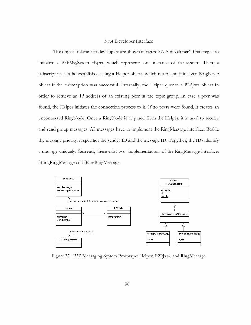
90
5.7.4 Developer Interface
The objects relevant to developers are shown in figure 37. A developer’s first step is to
initialize a P2PMsgSytem object, which represents one instance of the system. Then, a
subscription can be established using a Helper object, which returns an initialized RingNode
object if the subscription was successful. Internally, the Helper queries a P2PJxta object in
order to retrieve an IP address of an existing peer in the topic group. In case a peer was
found, the Helper initiates the connection process to it. If no peers were found, it creates an
unconnected RingNode. Once a RingNode is acquired from the Helper, it is used to receive
and send group messages. All messages have to implement the RingMessage interface. Beside
the message priority, it specifies the sender ID and the message ID. Together, the IDs identify
a message uniquely. Currently there exist two implementations of the RingMessage interface:
StringRingMessage and BytesRingMessage.
Figure 37. P2P Messaging System Prototype: Helper, P2PJxta, and RingMessage
91
5.8. Summary
We addressed the problems found in the previous chapter by the novel multi-ring
topology. The two potential solutions, tree and (single) ring topology, have serious
disadvantages, which the multi-ring aims to overcome. In addition to the bandwidth scalability
of rings, we introduced latency scalability by forming additional inner rings, which provide
short cuts to all ring sections. Inner ring peers, which are selected by their sending bandwidth,
are kept balanced in the outer rings. The robustness of rings is further improved by backup
links, which are activated when a node fails. Dual mode links avoid message collisions and
increase therefore the performance. Beside these concepts, we also presented mechanisms for
adding and removing ring nodes. Related topologies, like chordal rings, were discussed. Lastly,
we presented models and concepts of the P2P Messaging System prototype, which used JXTA
as its underlying peer-to-peer platform. The prototype reused many components of the system
presented in chapter 3. However, it is based on two central concepts. Firstly, the RingNode to
send and receive messages to and from the group. Secondly, the ModeLink implements the
dual mode links by exchanging special command messages. In the next chapter, we will
evaluate this prototype.

92
CHAPTER 6
EVALUATION
In this chapter, we evaluate the P2P Messaging System, which was presented in the
previous chapter. The first comparison contrasts its group communication characteristics to
the ones of the peer-to-peer platforms Pastry (Rowstron and others 2001)/Scribe (Rowstron
and Druschel 2001) and JXTA (JXTA 2002, Sun 2002). By focusing on group communication,
the P2P Messaging System provides several functional and conceptual advantages. The second
comparison is an experimental performance benchmark, which compares its efficiency to
JXTA’s propagate pipe. The tests examine the message rate depending on the message size
and number of receivers in order to gather information about efficiency and scalability. For
both, P2P Messaging System and JXTA, we present charts for the plain test results and the
scalability behavior. Lastly, comparison charts contrast the data rate, message rate, scalability,
and reliability of the two systems.
6.1. Comparison of Characteristics
This section compares the group communication characteristics of the P2P Messaging
System to related peer-to-peer systems. Chapter 2 reviewed several systems, but solely
Pastry/Scribe and JXTA are based peer-to-peer networks. The other systems are not
considered, as they rely on different infrastructures and differentiate between servers/brokers
and clients. For the comparison, we refer to feature matrixes of chapter 2. As Pastry/Scribe
and JXTA were discussed earlier, we focus on the P2P Messaging System.
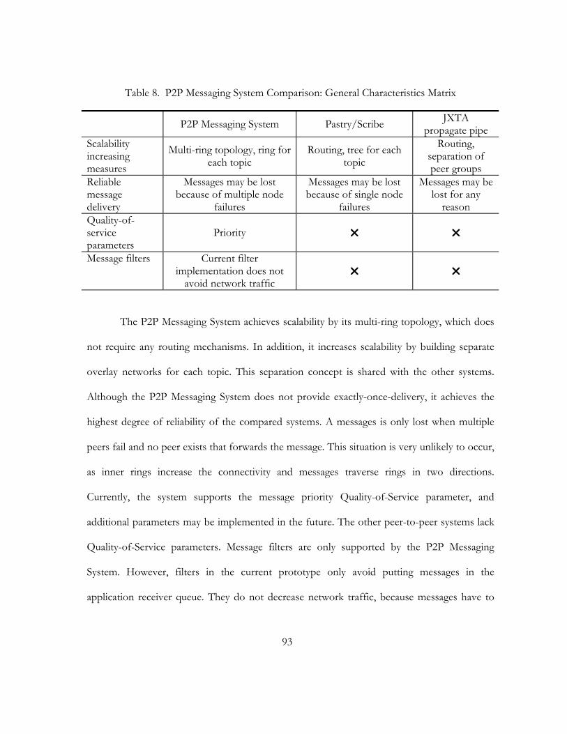
93
Table 8. P2P Messaging System Comparison: General Characteristics Matrix
P2P Messaging System Pastry/Scribe JXTA propagate pipe
Scalability increasing measures
Multi-ring topology, ring for each topic
Routing, tree for each topic
Routing, separation of peer groups
Reliable message delivery
Messages may be lost because of multiple node
failures
Messages may be lost because of single node
failures
Messages may be lost for any
reason Quality-of-service parameters
Priority
Message filters Current filter implementation does not
avoid network traffic
The P2P Messaging System achieves scalability by its multi-ring topology, which does
not require any routing mechanisms. In addition, it increases scalability by building separate
overlay networks for each topic. This separation concept is shared with the other systems.
Although the P2P Messaging System does not provide exactly-once-delivery, it achieves the
highest degree of reliability of the compared systems. A messages is only lost when multiple
peers fail and no peer exists that forwards the message. This situation is very unlikely to occur,
as inner rings increase the connectivity and messages traverse rings in two directions.
Currently, the system supports the message priority Quality-of-Service parameter, and
additional parameters may be implemented in the future. The other peer-to-peer systems lack
Quality-of-Service parameters. Message filters are only supported by the P2P Messaging
System. However, filters in the current prototype only avoid putting messages in the
application receiver queue. They do not decrease network traffic, because messages have to
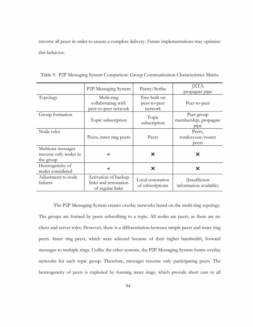
94
traverse all peers in order to ensure a complete delivery. Future implementations may optimize
this behavior.
Table 9. P2P Messaging System Comparison: Group Communication Characteristics Matrix
P2P Messaging System Pastry/Scribe JXTA propagate pipe
Topology Multi-ring collaborating with
peer-to-peer network
Tree built on peer-to-peer
network Peer-to-peer
Group formation Topic subscription Topic
subscription
Peer group membership, propagate
pipe Node roles
Peers, inner ring peers Peers Peers,
rendezvous/router peers
Multicast messages traverse only nodes in the group
Heterogeneity of nodes considered
Adjustment to node failures
Activation of backup links and restoration
of regular links
Local restoration of subscriptions
(Insufficient information available)
The P2P Messaging System creates overlay networks based on the multi-ring topology.
The groups are formed by peers subscribing to a topic. All nodes are peers, as there are no
client and server roles. However, there is a differentiation between simple peers and inner ring
peers. Inner ring peers, which were selected because of their higher bandwidth, forward
messages to multiple rings. Unlike the other systems, the P2P Messaging System forms overlay
networks for each topic group. Therefore, messages traverse only participating peers. The
heterogeneity of peers is exploited by forming inner rings, which provide short cuts to all
95
sections in the outer ring. The P2P Messaging System reacts fastest to node failures, as backup
links are immediately activated. The message delivery continues as soon as the failure is
detected. The regular link configuration is restored in parallel.
The comparison of the characteristics illustrated several advantages of the P2P
Messaging System. Its design considers several group communication requirements in peer-to-
peer networks. The other systems do not focus on group communication and concentrate on
a broader functionality. Especially JXTA has several additional features, for example group
membership services, HTTP gateways, and security considerations. In contrast, the P2P
Messaging System focuses on high performance, robustness, and scalability.
6.2. Experimental Performance Benchmarks
In this section, we compare the P2P Messaging System prototype to the peer-to-peer
platform JXTA. Pastry/Scribe Our goal is to evaluate the general efficiency of the systems,
their performance depending on the message size, and their scalability with an increasing
number of receiving peers.
6.2.1 Test Environment
Peer-to-peer networks are highly complex and heterogeneous because their size is not
limited and the equipment of peers differs greatly. In addition, peers have a dynamic and
unpredictable character, as they join and leave frequently. This complexity cannot be mirrored
in a computer laboratory without enormous effort. One approach would be to use a
simulation, but this prohibits making comparisons with existing products, which require a real
network, not a simulation, in order to operate. As our goal was to improve the group
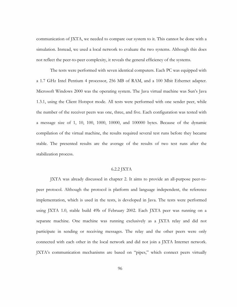
96
communication of JXTA, we needed to compare our system to it. This cannot be done with a
simulation. Instead, we used a local network to evaluate the two systems. Although this does
not reflect the peer-to-peer complexity, it reveals the general efficiency of the systems.
The tests were performed with seven identical computers. Each PC was equipped with
a 1.7 GHz Intel Pentium 4 processor, 256 MB of RAM, and a 100 Mbit Ethernet adapter.
Microsoft Windows 2000 was the operating system. The Java virtual machine was Sun’s Java
1.3.1, using the Client Hotspot mode. All tests were performed with one sender peer, while
the number of the receiver peers was one, three, and five. Each configuration was tested with
a message size of 1, 10, 100, 1000, 10000, and 100000 bytes. Because of the dynamic
compilation of the virtual machine, the results required several test runs before they became
stable. The presented results are the average of the results of two test runs after the
stabilization process.
6.2.2 JXTA
JXTA was already discussed in chapter 2. It aims to provide an all-purpose peer-to-
peer protocol. Although the protocol is platform and language independent, the reference
implementation, which is used in the tests, is developed in Java. The tests were performed
using JXTA 1.0, stable build 49b of February 2002. Each JXTA peer was running on a
separate machine. One machine was running exclusively as a JXTA relay and did not
participate in sending or receiving messages. The relay and the other peers were only
connected with each other in the local network and did not join a JXTA Internet network.
JXTA’s communication mechanisms are based on “pipes,” which connect peers virtually
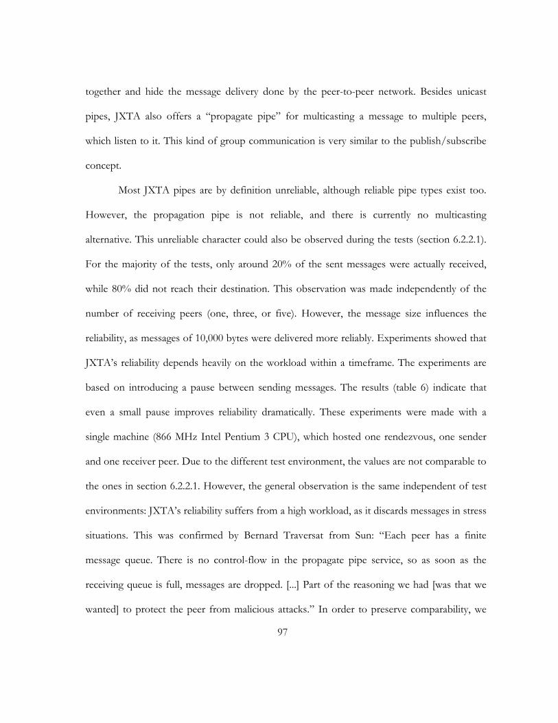
97
together and hide the message delivery done by the peer-to-peer network. Besides unicast
pipes, JXTA also offers a “propagate pipe” for multicasting a message to multiple peers,
which listen to it. This kind of group communication is very similar to the publish/subscribe
concept.
Most JXTA pipes are by definition unreliable, although reliable pipe types exist too.
However, the propagation pipe is not reliable, and there is currently no multicasting
alternative. This unreliable character could also be observed during the tests (section 6.2.2.1).
For the majority of the tests, only around 20% of the sent messages were actually received,
while 80% did not reach their destination. This observation was made independently of the
number of receiving peers (one, three, or five). However, the message size influences the
reliability, as messages of 10,000 bytes were delivered more reliably. Experiments showed that
JXTA’s reliability depends heavily on the workload within a timeframe. The experiments are
based on introducing a pause between sending messages. The results (table 6) indicate that
even a small pause improves reliability dramatically. These experiments were made with a
single machine (866 MHz Intel Pentium 3 CPU), which hosted one rendezvous, one sender
and one receiver peer. Due to the different test environment, the values are not comparable to
the ones in section 6.2.2.1. However, the general observation is the same independent of test
environments: JXTA’s reliability suffers from a high workload, as it discards messages in stress
situations. This was confirmed by Bernard Traversat from Sun: “Each peer has a finite
message queue. There is no control-flow in the propagate pipe service, so as soon as the
receiving queue is full, messages are dropped. [...] Part of the reasoning we had [was that we
wanted] to protect the peer from malicious attacks.” In order to preserve comparability, we
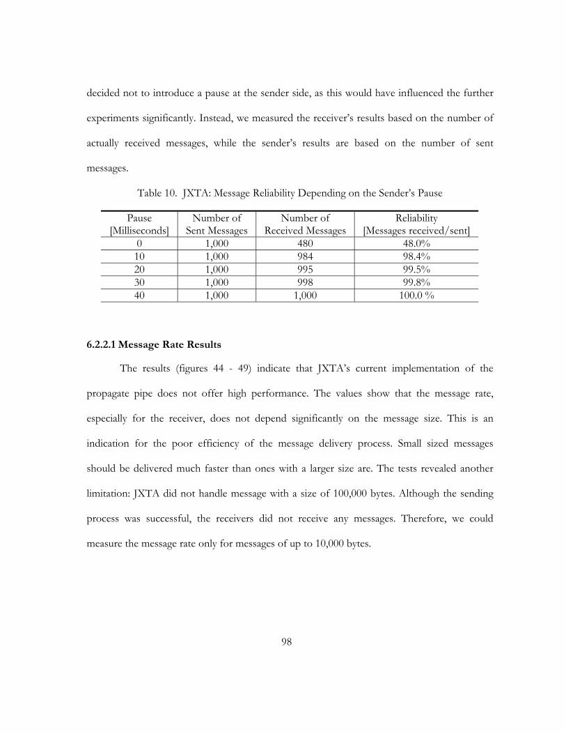
98
decided not to introduce a pause at the sender side, as this would have influenced the further
experiments significantly. Instead, we measured the receiver’s results based on the number of
actually received messages, while the sender’s results are based on the number of sent
messages.
Table 10. JXTA: Message Reliability Depending on the Sender’s Pause
Pause [Milliseconds]
Number of Sent Messages
Number of Received Messages
Reliability [Messages received/sent]
0 1,000 480 48.0% 10 1,000 984 98.4% 20 1,000 995 99.5% 30 1,000 998 99.8% 40 1,000 1,000 100.0 %
6.2.2.1 Message Rate Results
The results (figures 44 - 49) indicate that JXTA’s current implementation of the
propagate pipe does not offer high performance. The values show that the message rate,
especially for the receiver, does not depend significantly on the message size. This is an
indication for the poor efficiency of the message delivery process. Small sized messages
should be delivered much faster than ones with a larger size are. The tests revealed another
limitation: JXTA did not handle message with a size of 100,000 bytes. Although the sending
process was successful, the receivers did not receive any messages. Therefore, we could
measure the message rate only for messages of up to 10,000 bytes.

99
1 10 100 1,000 10,0005075
100125150175200225250275300325350375
SenderReceiver
Message Size [Bytes]
Mes
sage
Rat
e[M
essa
ges/
Seco
nd]
Figure 38. JXTA Message Rate: One Receiver
1 10 100 1,000 10,0005075
100125150175200225250275300325350375
SenderReceiver
Message Size [Bytes]
Mes
sage
Rat
e[M
essa
ges/
Seco
nd]
Figure 39. JXTA Message Rate: Three Receivers
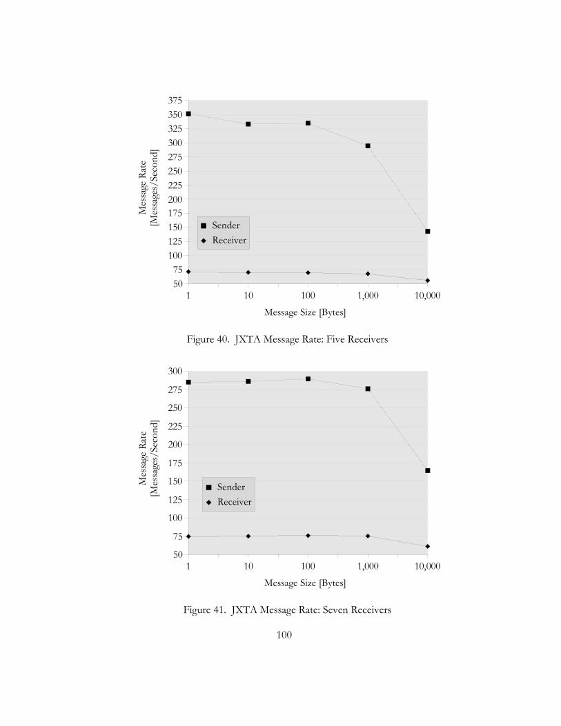
100
1 10 100 1,000 10,0005075
100125150175200225250275300325350375
SenderReceiver
Message Size [Bytes]
Mes
sage
Rat
e[M
essa
ges/
Seco
nd]
Figure 40. JXTA Message Rate: Five Receivers
1 10 100 1,000 10,00050
75
100
125
150
175
200
225
250
275
300
SenderReceiver
Message Size [Bytes]
Mes
sage
Rat
e[M
essa
ges/
Seco
nd]
Figure 41. JXTA Message Rate: Seven Receivers

101
1 10 100 1,000 10,00050
75
100
125
150175
200
225
250
275
300
325
SenderReceiver
Message Size [Bytes]
Mes
sage
Rat
e[M
essa
ges/
Seco
nd]
Figure 42. JXTA Message Rate: Nine Receivers
1 10 100 1,000 10,00050
75
100
125
150
175
200
225
250
275
300
SenderReceiver
Message Size [Bytes]
Mes
sage
Rat
e[M
essa
ges/
Seco
nd]
Figure 43. JXTA Message Rate: Eleven Receivers
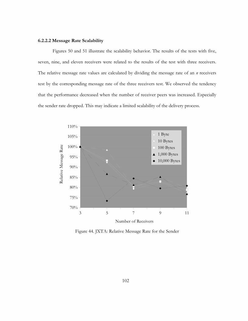
102
6.2.2.2 Message Rate Scalability
Figures 50 and 51 illustrate the scalability behavior. The results of the tests with five,
seven, nine, and eleven receivers were related to the results of the test with three receivers.
The relative message rate values are calculated by dividing the message rate of an n receivers
test by the corresponding message rate of the three receivers test. We observed the tendency
that the performance decreased when the number of receiver peers was increased. Especially
the sender rate dropped. This may indicate a limited scalability of the delivery process.
3 5 7 9 1170%
75%
80%
85%
90%
95%
100%
105%
110%
1 Byte10 Bytes100 Bytes1,000 Bytes10,000 Bytes
Number of Receivers
Relat
ive
Mes
sage
Rat
e
Figure 44. JXTA: Relative Message Rate for the Sender
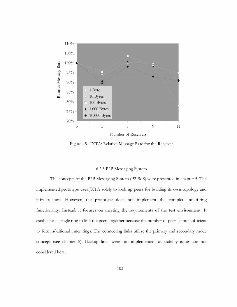
103
3 5 7 9 1170%
75%
80%
85%
90%
95%
100%
105%
110%
1 Byte10 Bytes100 Bytes1,000 Bytes10,000 Bytes
Number of Receivers
Relat
ive
Mes
sage
Rat
e
Figure 45. JXTA: Relative Message Rate for the Receiver
6.2.3 P2P Messaging System
The concepts of the P2P Messaging System (P2PMS) were presented in chapter 5. The
implemented prototype uses JXTA solely to look up peers for building its own topology and
infrastructure. However, the prototype does not implement the complete multi-ring
functionality. Instead, it focuses on meeting the requirements of the test environment. It
establishes a single ring to link the peers together because the number of peers is not sufficient
to form additional inner rings. The connecting links utilize the primary and secondary mode
concept (see chapter 5). Backup links were not implemented, as stability issues are not
considered here.
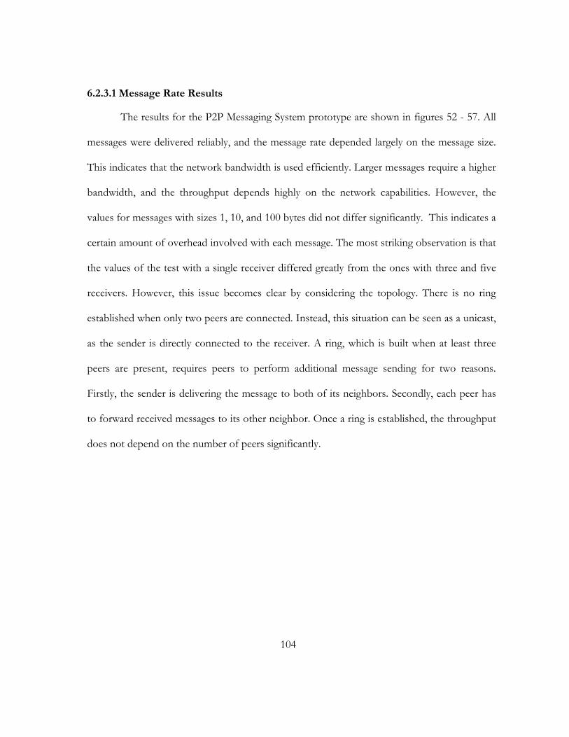
104
6.2.3.1 Message Rate Results
The results for the P2P Messaging System prototype are shown in figures 52 - 57. All
messages were delivered reliably, and the message rate depended largely on the message size.
This indicates that the network bandwidth is used efficiently. Larger messages require a higher
bandwidth, and the throughput depends highly on the network capabilities. However, the
values for messages with sizes 1, 10, and 100 bytes did not differ significantly. This indicates a
certain amount of overhead involved with each message. The most striking observation is that
the values of the test with a single receiver differed greatly from the ones with three and five
receivers. However, this issue becomes clear by considering the topology. There is no ring
established when only two peers are connected. Instead, this situation can be seen as a unicast,
as the sender is directly connected to the receiver. A ring, which is built when at least three
peers are present, requires peers to perform additional message sending for two reasons.
Firstly, the sender is delivering the message to both of its neighbors. Secondly, each peer has
to forward received messages to its other neighbor. Once a ring is established, the throughput
does not depend on the number of peers significantly.
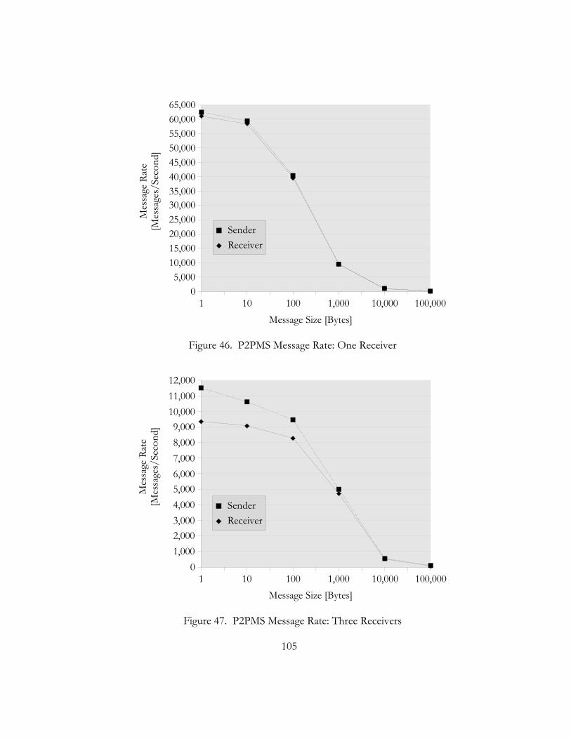
105
1 10 100 1,000 10,000 100,0000
5,00010,00015,00020,00025,00030,00035,00040,00045,00050,00055,00060,00065,000
SenderReceiver
Message Size [Bytes]
Mes
sage
Rat
e[M
essa
ges/
Seco
nd]
Figure 46. P2PMS Message Rate: One Receiver
1 10 100 1,000 10,000 100,0000
1,0002,0003,0004,0005,0006,0007,0008,0009,000
10,00011,00012,000
SenderReceiver
Message Size [Bytes]
Mes
sage
Rat
e[M
essa
ges/
Seco
nd]
Figure 47. P2PMS Message Rate: Three Receivers
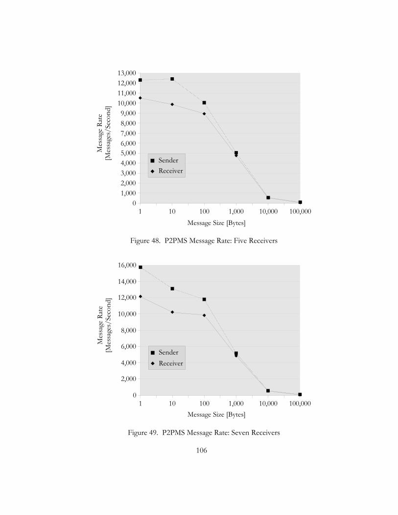
106
1 10 100 1,000 10,000 100,0000
1,0002,0003,0004,0005,0006,0007,0008,0009,000
10,00011,00012,00013,000
SenderReceiver
Message Size [Bytes]
Mes
sage
Rat
e[M
essa
ges/
Seco
nd]
Figure 48. P2PMS Message Rate: Five Receivers
1 10 100 1,000 10,000 100,0000
2,000
4,000
6,000
8,000
10,000
12,000
14,000
16,000
SenderReceiver
Message Size [Bytes]
Mes
sage
Rat
e[M
essa
ges/
Seco
nd]
Figure 49. P2PMS Message Rate: Seven Receivers
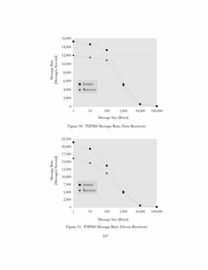
107
1 10 100 1,000 10,000 100,0000
2,000
4,000
6,000
8,000
10,000
12,000
14,000
16,000
SenderReceiver
Message Size [Bytes]
Mes
sage
Rat
e[M
essa
ges/
Seco
nd]
Figure 50. P2PMS Message Rate: Nine Receivers
1 10 100 1,000 10,000 100,0000
2,500
5,000
7,500
10,000
12,500
15,000
17,500
20,000
22,500
SenderReceiver
Message Size [Bytes]
Mes
sage
Rat
e[M
essa
ges/
Seco
nd]
Figure 51. P2PMS Message Rate: Eleven Receivers
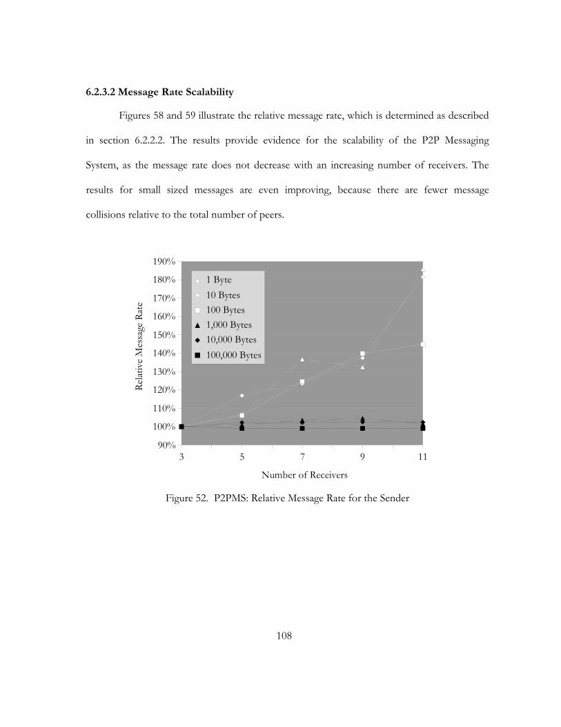
108
6.2.3.2 Message Rate Scalability
Figures 58 and 59 illustrate the relative message rate, which is determined as described
in section 6.2.2.2. The results provide evidence for the scalability of the P2P Messaging
System, as the message rate does not decrease with an increasing number of receivers. The
results for small sized messages are even improving, because there are fewer message
collisions relative to the total number of peers.
3 5 7 9 1190%
100%
110%
120%
130%
140%
150%
160%
170%
180%
190%
1 Byte10 Bytes100 Bytes1,000 Bytes10,000 Bytes100,000 Bytes
Number of Receivers
Relat
ive
Mes
sage
Rat
e
Figure 52. P2PMS: Relative Message Rate for the Sender
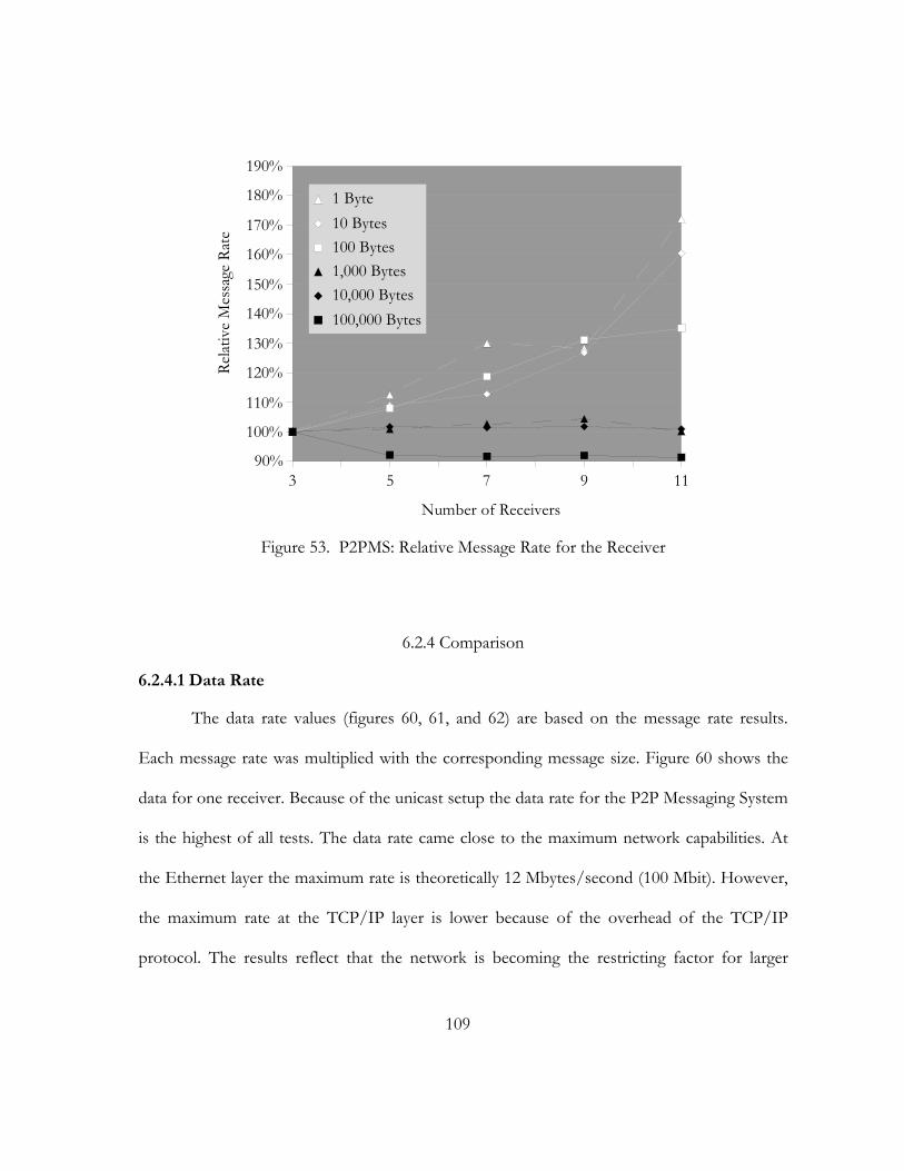
109
3 5 7 9 1190%
100%
110%
120%
130%
140%
150%
160%
170%
180%
190%
1 Byte10 Bytes100 Bytes1,000 Bytes10,000 Bytes100,000 Bytes
Number of Receivers
Relat
ive
Mes
sage
Rat
e
Figure 53. P2PMS: Relative Message Rate for the Receiver
6.2.4 Comparison
6.2.4.1 Data Rate
The data rate values (figures 60, 61, and 62) are based on the message rate results.
Each message rate was multiplied with the corresponding message size. Figure 60 shows the
data for one receiver. Because of the unicast setup the data rate for the P2P Messaging System
is the highest of all tests. The data rate came close to the maximum network capabilities. At
the Ethernet layer the maximum rate is theoretically 12 Mbytes/second (100 Mbit). However,
the maximum rate at the TCP/IP layer is lower because of the overhead of the TCP/IP
protocol. The results reflect that the network is becoming the restricting factor for larger
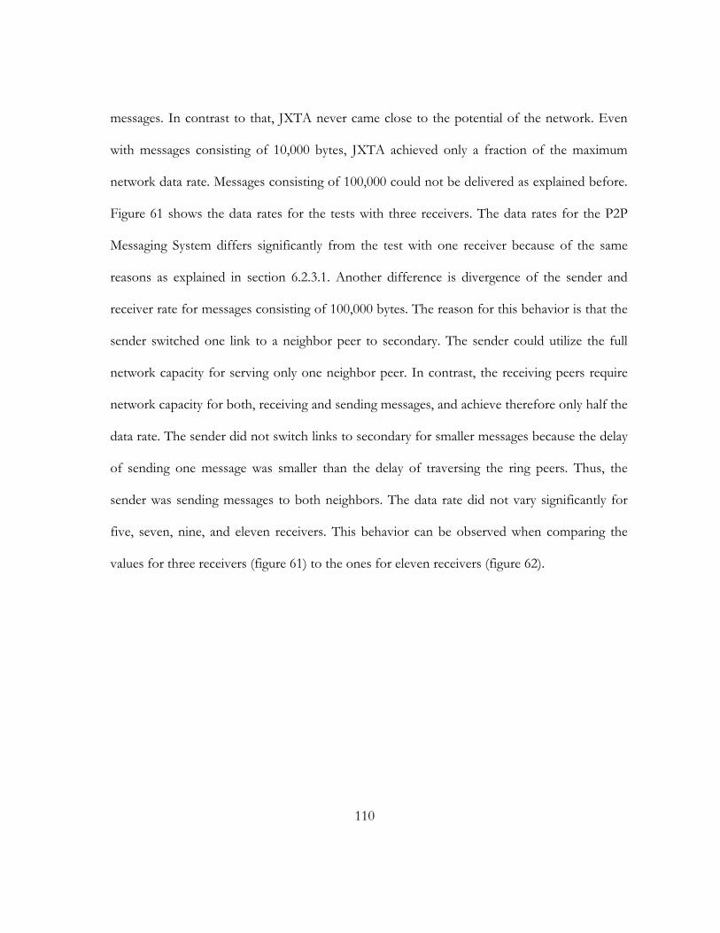
110
messages. In contrast to that, JXTA never came close to the potential of the network. Even
with messages consisting of 10,000 bytes, JXTA achieved only a fraction of the maximum
network data rate. Messages consisting of 100,000 could not be delivered as explained before.
Figure 61 shows the data rates for the tests with three receivers. The data rates for the P2P
Messaging System differs significantly from the test with one receiver because of the same
reasons as explained in section 6.2.3.1. Another difference is divergence of the sender and
receiver rate for messages consisting of 100,000 bytes. The reason for this behavior is that the
sender switched one link to a neighbor peer to secondary. The sender could utilize the full
network capacity for serving only one neighbor peer. In contrast, the receiving peers require
network capacity for both, receiving and sending messages, and achieve therefore only half the
data rate. The sender did not switch links to secondary for smaller messages because the delay
of sending one message was smaller than the delay of traversing the ring peers. Thus, the
sender was sending messages to both neighbors. The data rate did not vary significantly for
five, seven, nine, and eleven receivers. This behavior can be observed when comparing the
values for three receivers (figure 61) to the ones for eleven receivers (figure 62).
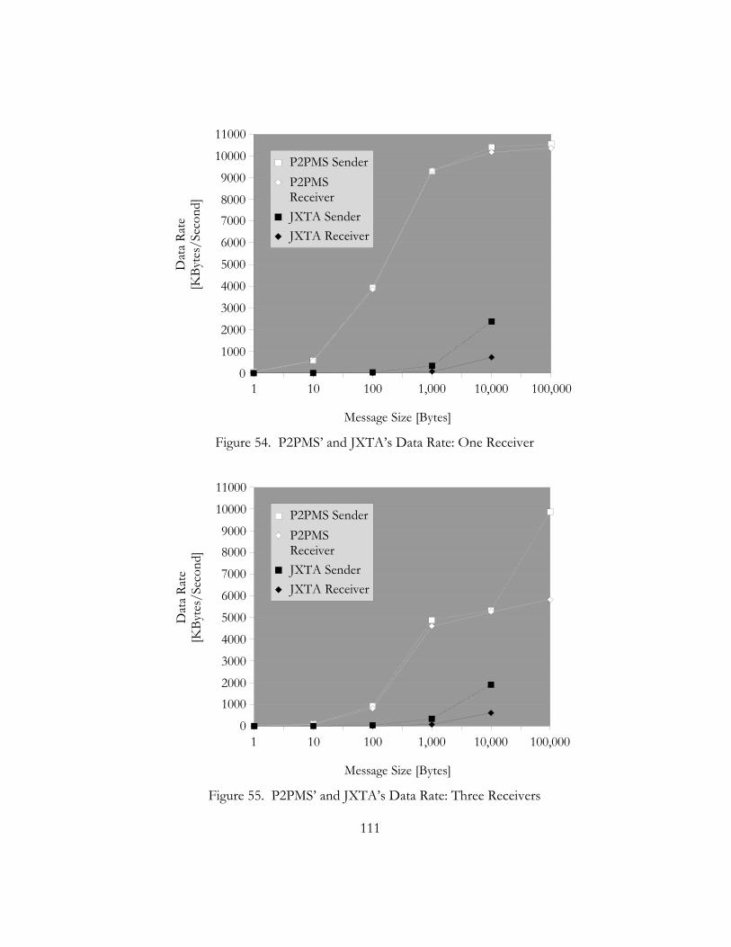
111
1 10 100 1,000 10,000 100,0000
1000
2000
3000
4000
5000
6000
70008000
9000
10000
11000
P2PMS SenderP2PMS ReceiverJXTA SenderJXTA Receiver
Message Size [Bytes]
Dat
a Ra
te[K
Byte
s/Se
cond
]
Figure 54. P2PMS’ and JXTA’s Data Rate: One Receiver
1 10 100 1,000 10,000 100,0000
10002000
3000
4000
5000
6000
7000
80009000
10000
11000
P2PMS SenderP2PMS ReceiverJXTA SenderJXTA Receiver
Message Size [Bytes]
Dat
a Ra
te[K
Byte
s/Se
cond
]
Figure 55. P2PMS’ and JXTA’s Data Rate: Three Receivers
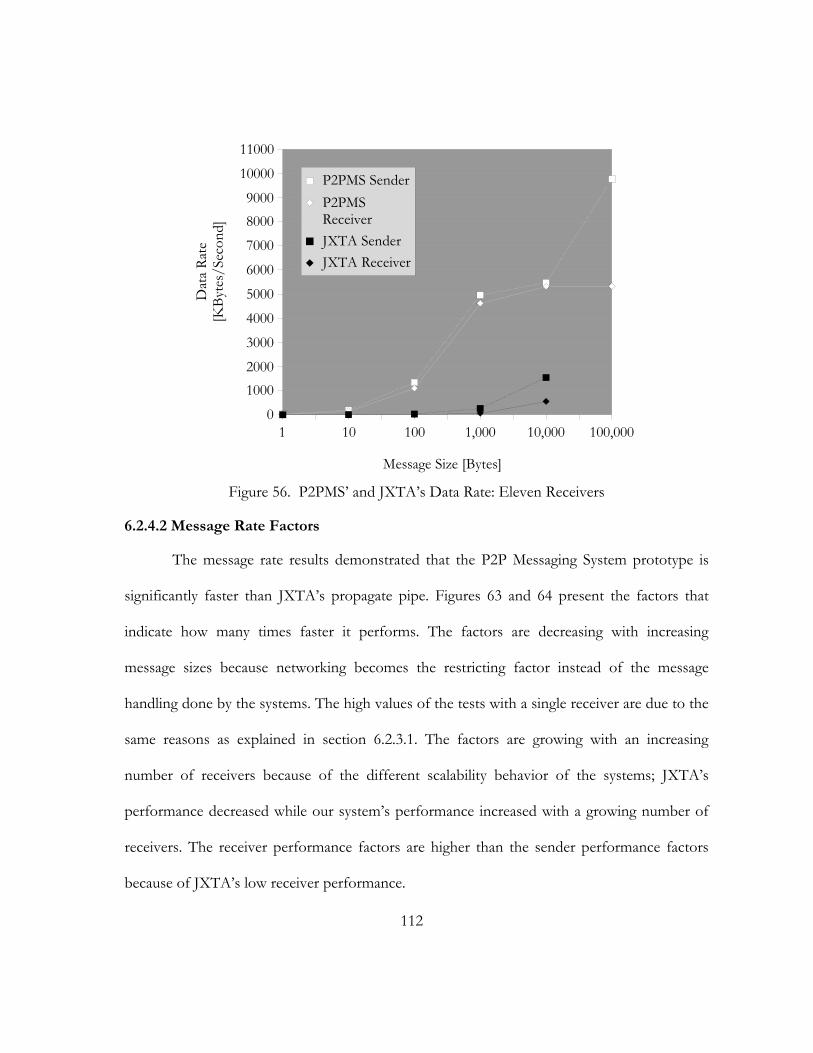
112
1 10 100 1,000 10,000 100,0000
10002000
3000
4000
5000
6000
7000
80009000
10000
11000
P2PMS SenderP2PMS ReceiverJXTA SenderJXTA Receiver
Message Size [Bytes]
Dat
a Ra
te[K
Byte
s/Se
cond
]
Figure 56. P2PMS’ and JXTA’s Data Rate: Eleven Receivers
6.2.4.2 Message Rate Factors
The message rate results demonstrated that the P2P Messaging System prototype is
significantly faster than JXTA’s propagate pipe. Figures 63 and 64 present the factors that
indicate how many times faster it performs. The factors are decreasing with increasing
message sizes because networking becomes the restricting factor instead of the message
handling done by the systems. The high values of the tests with a single receiver are due to the
same reasons as explained in section 6.2.3.1. The factors are growing with an increasing
number of receivers because of the different scalability behavior of the systems; JXTA’s
performance decreased while our system’s performance increased with a growing number of
receivers. The receiver performance factors are higher than the sender performance factors
because of JXTA’s low receiver performance.
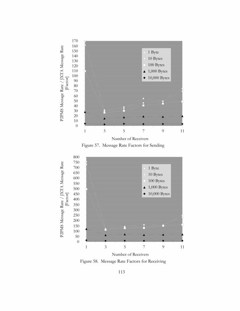
113
1 3 5 7 9 110
10 20 30 40 50 60 70 80 90
100 110 120 130 140 150 160 170
1 Byte10 Bytes100 Bytes1,000 Bytes10,000 Bytes
Number of Receivers
P2PM
S M
essa
ge R
ate
/ JX
TA M
essa
ge R
ate
[Fac
tor]
Figure 57. Message Rate Factors for Sending
1 3 5 7 9 110
50 100 150 200 250 300 350 400 450 500 550 600 650 700 750 800
1 Byte10 Bytes100 Bytes1,000 Bytes10,000 Bytes
Number of Receivers
P2PM
S M
essa
ge R
ate
/ JX
TA M
essa
ge R
ate
[Fac
tor]
Figure 58. Message Rate Factors for Receiving
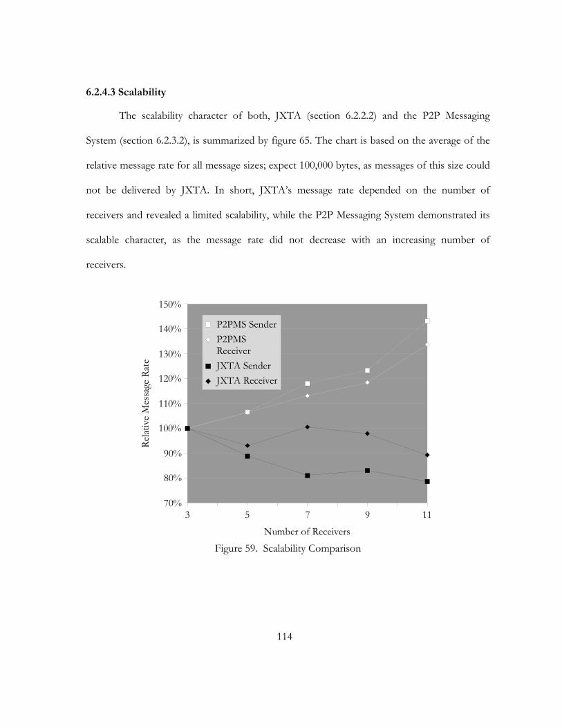
114
6.2.4.3 Scalability
The scalability character of both, JXTA (section 6.2.2.2) and the P2P Messaging
System (section 6.2.3.2), is summarized by figure 65. The chart is based on the average of the
relative message rate for all message sizes; expect 100,000 bytes, as messages of this size could
not be delivered by JXTA. In short, JXTA’s message rate depended on the number of
receivers and revealed a limited scalability, while the P2P Messaging System demonstrated its
scalable character, as the message rate did not decrease with an increasing number of
receivers.
3 5 7 9 1170%
80%
90%
100%
110%
120%
130%
140%
150%
P2PMS SenderP2PMS ReceiverJXTA SenderJXTA Receiver
Number of Receivers
Relat
ive
Mes
sage
Rat
e
Figure 59. Scalability Comparison
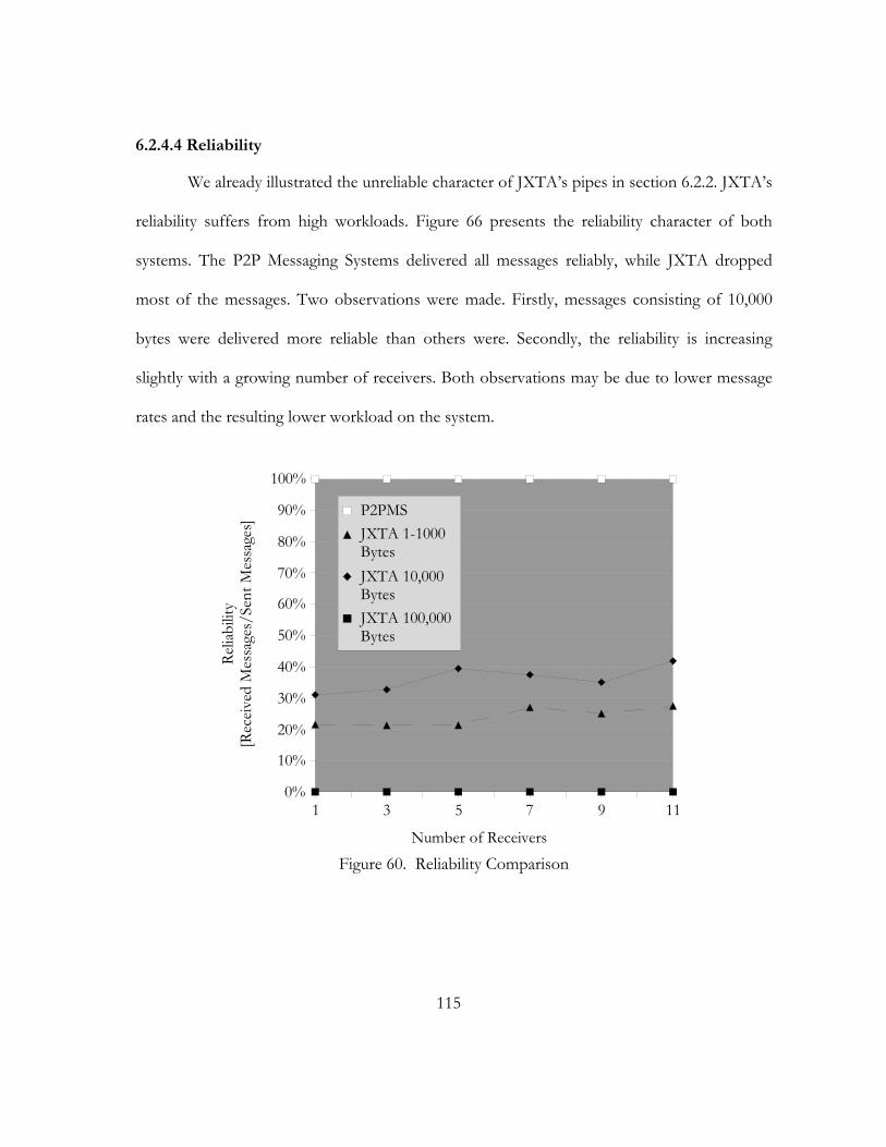
115
6.2.4.4 Reliability
We already illustrated the unreliable character of JXTA’s pipes in section 6.2.2. JXTA’s
reliability suffers from high workloads. Figure 66 presents the reliability character of both
systems. The P2P Messaging Systems delivered all messages reliably, while JXTA dropped
most of the messages. Two observations were made. Firstly, messages consisting of 10,000
bytes were delivered more reliable than others were. Secondly, the reliability is increasing
slightly with a growing number of receivers. Both observations may be due to lower message
rates and the resulting lower workload on the system.
1 3 5 7 9 110%
10%
20%
30%
40%
50%
60%
70%
80%
90%
100%
P2PMSJXTA 1-1000 BytesJXTA 10,000 BytesJXTA 100,000 Bytes
Number of Receivers
Relia
bilit
y[R
eceiv
ed M
essa
ges/
Sent
Mes
sage
s]
Figure 60. Reliability Comparison
116
6.2.5 Discussion
JXTA’s propagate pipe communication mechanism seems to be immature and not yet
optimized. This becomes more understandable when considering that JXTA is a rather new
product. An Engineering Manager from Sun Microsystems confirmed that there are known
performance issues. The main problems are the message queue management and the input
stream processing. Additionally, the queue design reveals a defensive but ineffective approach,
as it drops messages when the queue is full. Queues with a dynamic size, as used in the P2P
Messaging System prototype, allow higher reliability and performance at the cost of potential
higher memory consumption. Unlike JXTA, the P2P Messaging System was designed to
provide high performance as its primary goal. Thus, the efficiency of message queues, stream
processing, and their collaboration were considered from the beginning. In addition, the
topology was designed to meet high performance requirements as clarified in chapter 5. As a
result, the performances of the two systems differ greatly. This difference may even increase
in real peer-to-peer networks, because the P2P Messaging System creates overlay networks for
each group. In this way, the peers are connected directly together without using the existing
peer-to-peer infrastructure where many uninvolved peers may have to be traversed.
6.3. Summary
The evaluation indicated that the P2P Messaging System provides several
enhancements for group communication in peer-to-peer networks. A comparison of its
characteristics with Pastry/Scribe and JXTA presented several advantages. Because of its
multi-ring topology and the creation of overlay networks for each group, it achieves a more
117
robust and efficient message delivery. Further, the P2P Messaging System prototype
demonstrated its efficiency in an experimental performance benchmark with JXTA. We
illustrated that JXTA has serious reliability restrictions when the workload is high.
Nevertheless, we compared our system to JXTA’s propagate pipe, which is its common group
communication mechanism. The results indicated JXTA’s poor performance, which also
decreases with a growing number of receiving peers. In contrast, the P2P Messaging System
provided high message rates particularly for small message sizes. In addition, the tests
provided evidence for its scalable character. Aside from the one receiver configuration, which
allows an exceptionally high throughput due to its unicast setup, the throughput did not
decrease with a growing number of peers. Comparison charts demonstrated that the P2P
Messaging System significantly improves data rate, message rate, scalability, and reliability. In
short, we provided evidence for accomplishing our goal to improve group communication in
peer-to-peer networks.
118
CHAPTER 7
CONCLUSION
This thesis investigated in messaging technology and proposed two messaging
systems, which focus in server-less environments and high performance communication. In
particular, peer-to-peer networks were targeted, because they lacked efficient group
communication methods.
We showed that the majority of the current messaging systems are tailored to the
needs of enterprises and their infrastructure. Enterprise applications usually require exactly-
once-delivery, which includes the storing messages persistently. This does not come free,
because access to persistent storage implies a greater overhead. In addition, dedicated servers
are needed, which have to be setup and maintained. These were the reasons to design and
implement a messaging system, which can be applied in server-less environments. However,
its scalability was restricted due its network topology. Therefore, we investigated in current
messaging and peer-to-peer topologies. To meet the requirements of highly dynamic and
heterogeneous peer-to-peer networks, the novel multi-ring topology was proposed, which
aims to combine the robustness and manageability of ring topologies and the scalability of tree
topologies. Multiple inner rings provide shortcuts to all ring sections and therefore reduce the
average latency. Inner rings are established considering the heterogeneity of the peer-to-peer
network.
The proposed system adapts to the dynamic of the peer-to-peer networks. Peers may
create topic-based groups at any time themselves, without the need of any centralized

119
management. In short, it gives them the communication tool to collaborate. Applications are
various: instant discussion, file sharing, online conferences, audio or video broadcasting, and
interactive distant learning are just examples.
A prototype of the P2P Messaging System was implemented and successfully
evaluated. Experimental performance benchmarks provided evidence for the efficiency and
scalability of the system. However, the system still has to proof its usability in practice. Peer-
to-peer networks are highly complex and may require unforeseen adjustments to it In
addition, there are some issues, which may complement the system. For example, it could be
investigated how persistent storage could be utilized to increase reliability and allow time
independent delivery. Another extension point would be to address management functions for
private groups. Instead of a completely decentralized management, it would be necessary for
some applications to restrict or control group membership.
Overall, the main contribution of this thesis is to help peer-to-peer networks in the
phase of maturing. Proven communication principles of messaging systems are adapted to
allow efficient group communication among peers.

120
REFERENCES
Aiello, William, Sandeep N. Bhatt, Fan R. K. Chung, Arnold L. Rosenberg, and Ramesh K. Sitaraman. 2001. Augmented ring networks. IEEE Transactions on Parallel and Distributed Systems, vol. 12, no. 6, June: 598-609
Aberer, Karl, Magdalena Punceva, Manfred Hauswirth, and Roman Schmidt. 2002. Improving Data Access in P2P Systems. IEEE Internet Computing, January/February: 58-67.
Carzaniga, Antonio. 1998. Architectures for an Event Notification Service Scalable to Wide-area Networks. Ph. D. diss., Politecnico di Milano, Italy.
Carzaniga, Antonio and Alexander. L. Wolf. 2001. Content-based Networking: A New Communication Infrastructure. NSF Workshop on an Infrastructure for Mobile and Wireless Systems. In conjunction with the International Conference on Computer Communications and Networks ICCCN. Scottsdale, AZ. October.
Carzaniga, Antonio, David S. Rosenblum, and Alexander. L. Wolf. 2001. Design and Evaluation of a Wide-Area Event Notification Service. ACM Transactions on Computer Systems, vol. 19, no. 3, August: 332-383.
Chawathe, Y. 2000. Scattercast: An Architecture for Internet Broadcast Distribution as an Infrastructure Service. Ph. D. diss., University of California, Berkeley.
Chawathe, Y., S. McCanne, and E. Brewer. 2000. RMX: Reliable Multicast for Heterogeneous Networks. In Proceedings of INFOCOM 2000. Nineteenth Annual Joint Conference of the IEEE Computer and Communications Societies, vol. 2: 795- 804.
Chu, Yang-hua, Sanjay G. Rao, and Hui Zhang. 2000. A case for end system multicast. ACM SIGMETRICS Performance Evaluation Review, vol. 28, no. 1: 1-12
Dalal, Yogen K., and Robert Metcalfe. 1978. Reverse path forwarding of broadcast packets. Communications of the ACM, vol. 21, no. 12: 1040–1048.
Deering, S. 1989. Host Extensions for IP multicasting. Internet RFC 1112. Available online: http://www.ietf.org/rfc/rfc1112.txt [Accessed 11 March 2002]
Deering, S., Hinden, R. 1998. Internet Protocol, Version 6 (IPv6) Specification. Internet RFC 2460. Available online: http://www.ietf.org/rfc/rfc2460.txt [Accessed 20 April 2002]
DistributedNet. 2002. Homepage. Available online: http://www.distributed.net [Accessed 20 April 2002]

121
Druschel, Peter, and Antony Rowstron. 2001. PAST: a large-scale, persistent peer-to-peer storage utility. Proceedings of the Eighth Workshop on Hot Topics in Operating Systems. IEEE Computing Sociecty. Los Alamitos, CA: 75-80.
Floyd, Sally, Van Jacobson, Steve McCanne, Ching-Gung Liu, and Lixia Zhang. 1995. A reliable multicast framework for light-weight sessions and application level framing. ACM SIGCOMM Computer Communication Review, vol. 25, no. 4: 342-356.
Fox, Geoffrey, Shrideep Pallickara, Xi Rao, and Qinglin Pei. 2002. A Scaleable Event Infrastructure for Peer to Peer Grids. Submitted to: The Eleventh IEEE International Symposium on High-Performance Distributed Computing, Edinburgh, Scotland
Fox, Geoffrey and Shrideep Pallickara. 2002a. The Narada Event Brokering System: Overview and Extensions. Submitted to: International Conference on Parallel and Distributed Processing Techniques and Applications (PDPTA'02).
Fox, Geoffrey and Shrideep Pallickara. 2002b. JMS Compliance in the Narada Event Brokering System. Submitted to: International Conference on Internet Computing (IC-02).
Gnutella. 2000. Gnutella protocol specification. Available online: http://www.clip2.com/GnutellaProtocol04.pdf [Accessed 30 March 2002]
Gnutella. 2002. Available online: http://www.gnutella.wego.com or http://www.gnutelliums.com [Accessed 30 March 2002]
Gong, L. 2001. JXTA: A Network Programming Environment. IEEE Internet Computing, vol. 5, no. 3, May/June: 88-95.
Hinden, R., Deering, S. 1998. IP Version 6 Addressing Architecture. Internet RFC 2373. Available online: http://www.ietf.org/rfc/rfc2373.txt [Accessed 20 April 2002]
IIT GmbH (IIT). 2002. SwiftMQ. Bremen, Germany. Available online: http://www.swiftmq.com [Accessed 11 March 2002]
IBM. 2002. Websphere MQ and MQSeries. Homepage on-line. http://www-3.ibm.com/software/ts/mqseries/ [Accessed 05 April 2002]
Jannotti, John David K. Gifford, Kirk L. Johnson, M. Frans Kaashoek, and James W. O’Toole. 2000. Overcast: Reliable Multicasting with an Overlay Network. In Proceedings of OSDI (October 2000).
Jungnickel, Dieter. 1999. Algorithms and Computation in Mathematics.Vol.5, Graphs, Networks and Algorithms. Springer-Verlag.
122
Kontiki, Inc (Kontiki). 2002. Homepage. Available online: http://www.kontiki.com [Accessed 20 April 2002]
Liebeherr, J., M. Nahas. 2001. Application-layer multicast with Delaunay triangulations. Global Telecommunications Conference. IEEE GLOBECOM 2001, vol. 3: 1651-1655.
Lin, John C. and Sanjoy Paul. 1996. RMTP: A reliable multicast transport protocol. In Proceedings of IEEE INFOCOM, pages 1414-1424. San Francisco, CA.
Martin, Robert C., Dirk Riehle, and Frank Buschmann, editors. 1998. Pattern Languages of Program Design 3. Reading, MA: Addison-Wesley.
JXTA. 2002. Project JXTA Homepage. Available online: http://www.jxta.org [Accessed 30 March 2002]
Microsoft Developer Network (MSDN). 2001. “COM+ Events” MSDN Library. Available online: http://msdn.microsoft.com/library/default.asp?url=/library/en-us/cossdk/htm/pgservices_events_20rp.asp [Accessed 11 March 2002]
Object Management Group (OMG). 2000. Notification Service Specification Version 1.0. Available online: http://www.omg.org/technology/documents/formal/notification_service.htm [Accessed 11 March 2002]
Object Management Group (OMG). 2001. Event Service Specification Version 1.1. Available online: http://www.omg.org/technology/documents/formal/event_service.htm [Accessed 11 March 2002]
Pallickara, Shrideep Bhaskaran. 2001. A Grid Event Service. Ph. D. diss., Syracuse University
Pendarakis, D., S. Shi, D. Verma, and M. Waldvogel. 2001. ALMI: an application level multicast infrastructure. Proceedings of 3rd USENIX Symposium on Internet Technologies and Systems: 49-60.
Ratnasamy, S., P. Francis, M. Handley, R. Karp, and S. Shenker. 2001. A Scalable Content-Addressable Network. ACM Computer Communication Review, vol. 31, no. 4, USA, October: 161-72
Rosenblum, David S., Alexander L. Wolf. 1997. A Design Framework for Internet-Scale Event Observation and Notification. Proceedings of the Sixth European Software Engineering Conference (ESEC/FSE 97)
Rowstron, Antony, Anne-Marie Kermarrec, Miguel Castro, and Peter Druschel. 2001. Scribe: The design of a large-scale event notification infrastructure. Proceedings of the Third International Workshop on Networked Group Communications, London, UK, November: 30-43

123
Rowstron, Antony, and Peter Druschel. 2001. Pastry: Scalable, distributed object location and routing for large-scale peer-to-peer systems. IFIP/ACM International Conference on Distributed Systems Platforms (Middleware), Heidelberg, Germany, November: 329-350.
Sibai, Fadi. 1998. The hyper-ring network: a cost-efficient topology for scalable multicomputers, Proceedings of the 1998 ACM symposium on Applied Computing, February 27-March 01, Atlanta, Georgia: 598-606
Stoica, I., R. Morris, D. Karger, Frans M. Kaashoek, and H. Balakrishnan. 2001. Chord: a scalable peer-to-peer lookup service for Internet applications. ACM Computer Communication Review, vol. 31, no. 4, USA, October: 149-60.
Sonic Software Cooperation (Sonic). 2002. Homepage on-line. http://www.sonicsoftware.com [Accessed 05 April 2002]
Sun Microsystems, Inc. (Sun). 2001. Java™ Message Service Specification Version: 1.0.2b. Available online: http://java.sun.com/products/jms/docs.html [Accessed 11 March 2002]
Sun Microsystems, Inc. (Sun). 2002. JXTA v1.0 Protocols. Available online: http://spec.jxta.org/v1.0/docbook/JXTAProtocols.pdf [Accessed 16 April 2002]
Talarian Cooperation (Talarian). 2002. SmartSockets for JMS. Homepage on-line. http://www.talarian.com [Accessed 05 April 2002]
Zhao, Ben Y., John D. Kubiatowicz, and Anthony D. Joseph. 2001. Tapestry: An infrastructure for fault-resilient wide-area location and routing. Technical Report UCB//CSD-01-1141, University of California Berkeley.
Zhuang, Shelley Q., Ben Y. Zhao, Anthony D. Joseph, Randy H. Katz, John D. Kubiatowicz. 2001. Bayeux: An Architecture for Scalable and Faulttolerant Widearea Data Dissemination. Proceedings of ACM Eleventh International Workshop on Network and Operating Systems Support for Digital Audio and Video, Port Jefferson, New York: 11-20
124
VITA
Markus Oliver Junginger was born on May, 8th, 1977 in Heidenheim, Germany. He
was educated in a local public school and received the “Allgemeine Hochschulreife (Abitur)”
from a high school in Heidenheim in 1996. In 1986, he began programming as an autodidact,
and developed several computer programs during the following years. One of his programs
received the award “Programm des Monats” (program of the month) of a German computer
magazine in 1995 and was published later by Maxon. From August 1997 to August 1998, he
was committed to community service, which he fulfilled at hospital and nursing service in
Heidenheim. Among his tasks were software development, nursing, and administrative office
work. In 1998, he joined University of Applied Sciences in Augsburg, Germany, in order to
study Multimedia, an interdisciplinary course of study in the fields of computer science and
graphic design. Besides his studies, he also worked as a freelancer for several companies, and
developed web applications. In April 2000, he received the certificate “SUN certified
programmer for the Java 2 Platform.” In 2001, he chose the computer science study track. For
the integrated practical semester, he joined MobileX, a company dedicated to mobile
distributed applications located in Munich, Germany, from February 2001 to July 2001. Here,
he was involved in the design and development of several mobile web applications. In August
2001, he joined the University of Missouri, Kansas City as an exchange student and was
awarded a DAAD scholarship. Mr. Junginger completes his Master degree at the University of
Missouri, Kansas in May 2003 (“Best Student Award”). In 2003, he also plans to complete the
German degree “Diplom Informatiker (FH)” at the University of Applied Sciences in

125
Augsburg. His primary areas of interest are distributed systems, peer-to-peer networks, object-
oriented development, Java, and multimedia applications. He wants to continue his research
on peer-to-peer networks, messaging and peer collaboration.