a guide to working with electricity for electrical workers · working with electricity for...
TRANSCRIPT

A Guide to
Working With Electricity
for Electrical Workers
Occupational Safety and Health Division
N.C. Department of Labor
1101 Mail Service Center
Raleigh, NC 27699-1101
Cherie Berry
Commissioner of Labor
����������� ��������
�����������
23

N.C. Department of Labor
Occupational Safety and Health Program
Cherie Berry
Commissioner of Labor
OSHA State Plan Designee
Allen McNeely
Deputy Commissioner for Safety and Health
Kevin Beauregard
Assistant Deputy Commissioner for Safety and Health
Bobby Davis
Reviewer
Acknowledgments
A Guide to Working with Electricity was prepared by the L.A. Weaver Company; U.S. Department ofLabor, Occupational Safety and Health Administration; and U.S. Department of Health and Human Services.The information in this guide was updated in 2012.
This guide is intended to be consistent with all existing OSHA standards; therefore, if an area is con-sidered by the reader to be inconsistent with a standard, then the OSHA standard must be followed.
To obtain additional copies of this guide, or if you have questions about North Carolina occupational safety and health stan-
dards or rules, please contact:
N.C. Department of Labor
Education, Training and Technical Assistance Bureau
1101 Mail Service Center
Raleigh, NC 27699-1101
Phone: 919-807-2875 or 1-800-NC-LABOR (1-800-625-2267)
____________________
Additional sources of information are listed on the inside back cover of this guide.
____________________
The projected cost of the NCDOL OSH program for federal fiscal year 2011–2012 is $17,841,216. Federal funding pro vides approximately 31 percent ($5,501,500) ofthis total.
Revised 10/12

ContentsPart Page
Foreword . . . . . . . . . . . . . . . . . . . . . . . . . . . . . . . . . . . . . . . . . . . . . . . .1iiv
1 Electrical Accidents . . . . . . . . . . . . . . . . . . . . . . . . . . . . . . . . . . .1ii1
2 Static Electricity . . . . . . . . . . . . . . . . . . . . . . . . . . . . . . . . . . . . . . ii19
3 Arc Flash/NFPA 70E . . . . . . . . . . . . . . . . . . . . . . . . . . . . . . . . . . . ii11
4 Electrical Safety Program . . . . . . . . . . . . . . . . . . . . . . . . . . . . . . . . ii14
5 Ground-Fault Circuit Protection . . . . . . . . . . . . . . . . . . . . . . . . . . . . . ii20
6 OSHA Standards Related to Lockout/Tagout or the Control of Energy DuringMaintenance . . . . . . . . . . . . . . . . . . . . . . . . . . . . . . . . . . . . . . . . ii29
7 Self-Inspection Checklist for the Electrician . . . . . . . . . . . . . . . . . . . . . . ii37
Terms and Definitions . . . . . . . . . . . . . . . . . . . . . . . . . . . . . . . . . . ii40
References . . . . . . . . . . . . . . . . . . . . . . . . . . . . . . . . . . . . . . . . . ii42
iii

ForewordEveryone identifies electricity by what it does. Electricity gives us light, heat and power. It brings us radio, television,
motion pictures and the telephone. Modern industry could not exist without electricity. Electric motors run drills, milling
machines, lathes and other tools. These tools mass-produce parts that are quickly assembled on electrically operated con-
veyer belts. Powerful electric cranes lift huge loads. Electricity runs elevators and escalators in stores and office build-
ings. Electric signs advertise products and businesses. Adding machines, computers and other electrical devices save
office workers time and effort.
Electricity is a very potent energy form. Used carelessly, it can deliver deadly shocks and injuries. During the past
decade, the National Center for Health Statistics has reported about 1,000 accidental electrocutions annually in the United
States. About a fourth of these deaths happen in industries or on farms.
In North Carolina, DOL inspectors enforce the federal Occupational Safety and Health Act through a state plan
approved by the U.S. Department of Labor. The Occupational Safety and Health Division of the N.C. Department of
Labor offers many educational programs to the public and produces publications, including this guide, to help inform
people about their rights and responsibilities regarding occupational safety and health.
This guide has been developed to assist a qualified employee, one who has the training, skills and technical knowledge
of electrical safety. When looking through this guide, please remember the DOL mission is greater than just enforcement
of regulations. An equally important goal is to help people find ways to create safe workplaces. This booklet, like the
other educational materials produced by the N.C. Department of Labor, can help.
Cherie Berry
Commissioner of Labor
iv
1
Electrical Accidents
The Effects of Electricity Upon the Human BodyElectricity is essential to modern life. Commonly used at both home and on the job, benefits offered by electricity are
realized every day through its use. Many workers in different occupations and industries are exposed to electrical energy
daily during the performance of their duties. Some employees work with electricity directly, as is the case with engineers,
electricians, electronic technicians and power line workers. Others, such as office workers and salespeople, work with it
indirectly. Although you cannot taste or smell electricity, inadvertent contact can surely make one aware of its presence.
Dangers posed by electricity are apparent, particularly when contact occurs accidentally or otherwise that can be felt and
its affect noted on the human body. There are two kinds of electricity—static (stationary) and dynamic (moving).
Dynamic electricity is characterized by the flow of electrons through a conductor. As a source of power, electricity is
accepted without much thought to the hazards encountered. Perhaps because it has become such a familiar part of our sur-
roundings, it often is not treated with the respect it deserves.
OSHA’s electrical standards address concerns that electricity has long been recognized as a serious workplace hazard,
exposing employees to such dangers as electric shock, electrocution, burns, fires and explosions. In 2006, the Bureau of
Labor Statistics reported that 5,703 deaths occurred in private sector workplaces having 11 or more workers. About 4 per-
cent of the fatalities, 247 deaths, were the direct result of electrocutions at work. OSHA’s electrical standards help mini-
mize these potential hazards by specifying safety aspects in the design and use of electrical equipment and systems.
To handle electricity safely, it is necessary to understand how it acts, how it can be directed, what hazards it presents, and
how these hazards can be controlled. Operating an electric switch may be considered in comparison to turning on a water
faucet. Behind the faucet or switch there must be a source of water or electricity, with something to transport it and with
pressure to make it flow. In the case of water, the source is a reservoir or pumping station; the transportation is through pipes;
and the force to make it flow is pressure, provided by a pump. For electricity, the source is the power generating station; cur-
rent travels through electric conductors in the form of wires; and pressure, measured in volts, is provided by a generator.
When you turn on an electrical power tool or device, such as your circular saw or throw a circuit breaker, you allow
current to flow from the generating source, through conductors (wiring), to the area of demand or load (i.e., equipment or
lighting). A complete circuit is necessary for the flow of electricity through a conductor. A complete circuit is made up of
a source of electricity, a conductor and a consuming device (load), such as a portable drill. The equation known as Ohm’s
law (volts = current x resistance; or V = IR) shows the relationship between three factors. This relationship makes it
possible to change the qualities of an electrical current but keep an equivalent amount of power.
Resistance to the flow of electricity is measured in ohms and varies widely. It is determined by three factors: the nature
of the substance itself, the length and cross-sectional area (size) of the substance, and the temperature of the substance.
Some substances, such as metals, offer very little resistance to the flow of electric current and are called conductors.
Other substances, such as porcelain, pottery and dry wood, offer such a high resistance that they can be used to prevent
the flow of electric current and are called insulators. Dry wood has a high resistance, but when saturated with water its
resistance drops to the point where it will readily conduct electricity. The same is true of human skin. When it is dry, skin
has a fairly high resistance to electric current; but when it is moist, there is a radical drop in resistance. Pure water is a
poor conductor, but small amounts of impurities, such as salt and acid (both of which are contained in perspiration), make
it a ready conductor. When water is present either in the environment or on the skin, anyone working with electricity
should exercise even more caution than they normally would.
How Shocks OccurElectricity travels in closed circuits, and its normal route is through a conductor. Electric shock occurs when the body
becomes a part of the electric circuit. The current must enter the body at one point and leave at another. Electric shock
normally occurs in one of three ways. The individual, while in contact with the ground, must come in contact with both
wires of the electric circuit, one wire of an energized circuit and the ground, or a metallic part that has become “hot” by
contact with an energized conductor.
1

The metal parts of electric tools and machines may become energized if there is a break in the insulation of the tool or
machine wiring. The worker using these tools and machines is made less vulnerable to electric shock when there is a low-
resistance path from the metallic case of the tool or machine to the ground. This is done through the use of an equipment
grounding conductor, a low-resistance wire that causes the unwanted current to pass directly to the ground, thereby great-
ly reducing the amount of current passing through the body of the person in contact with the tool or machine. If the equip-
ment grounding conductor has been properly installed, it has a low resistance to ground, and the worker is protected.
Controlling Electrical HazardsThe severity of the shock received when a person becomes a part of an electric circuit is affected by three primary fac-
tors: the amount of current flowing through the body (measured in amperes), the path of the current through the body and
the length of time the body is in the circuit. Other factors that may affect the severity of shock are the frequency of the
current, the phase of the heart cycle when shock occurs and the general health of the person.
The effects of electric shock depends upon the type of circuit, its voltage, resistance, current, pathway through the body
and duration of the contact. Effects can range from a barely perceptible tingle to immediate cardiac arrest. Although there
are no absolute limits or even known values that show the exact injury from any given current, Table 1 shows the general
relationship between the degree of injury and amount of current for a 60-cycle hand-to-foot path of one second’s duration
of shock.
The table also illustrates that a difference of less than 100 milliamperes exists between a current that is barely percepti-
ble and one that can kill. Muscular contraction caused by stimulation may not allow the victim to free himself or herself
from the circuit, and the increased duration of exposure increases the dangers to the shock victim. For example, a current
of 100 milliamperes for 3 seconds is equivalent to a current of 900 milliamperes applied for .03 seconds in causing ven-
tricular fibrillation. The so-called low voltages can be extremely dangerous because, all other factors being equal, the
degree of injury is proportional to the length of time the body is in the circuit. Low voltage does not imply low hazard! A
severe shock can cause considerably more damage to the body than is visible. For example, a person may suffer internal
hemorrhages and destruction of tissues, nerves and muscles. In addition, shock is often only the beginning in a chain of
events. The final injury may well be from a fall, cuts or burns.
Table 1
Effects of Electric Current on Body
Electrical injuries may occur in various ways: direct contact with electrical energy, injuries that occur when electricity
arcs (an arc is a flow of electrons through a gas, such as air) to a victim at ground potential (supplying an alternative path
to ground), flash burns from the heat generated by an electrical arc, and flame burns from the ignition of clothing or other
combustible, nonelectrical materials. Direct contact and arcing injuries produce similar effects. Burns at the point of con-
tact with electrical energy can be caused by arcing to the skin, heating at the point of contact by a high-resistance contact
or higher voltage currents. Contact with a source of electrical energy can cause external as well as internal burns.
Exposure to higher voltages will normally result in burns at the sites where the electrical current enters and exits the
human body. High voltage contact burns may display only small superficial injury; however, the danger of these deep
2
Current Reaction
1 mA Perception level. Just a faint tingle.
5 mA Slight shock felt; not painful by disturbing.
6–25 mA (Women) Painful shock; muscular control is lost.
9–30 mA (Men) Called the freezing current or “let-go” range.
50–150 mA Extreme pain, respiratory arrest, severe muscular contractions.
Individual cannot let go. Death is possible.
1,000–4,300 mA Ventricular fibrillation. (The rhythmic pumping action of the heart ceases.)
Muscular contraction and nerve damage occur. Death is most likely.
10,000 mA Cardiac arrest, severe burns and probable death.

burns destroying tissue just beneath the skin exists. In addition, internal blood vessels may clot, nerves in the area of the
contact point may be damaged, and muscle contractions may cause skeletal fractures either directly or in association with
falls from elevation. It is also possible to have a low-voltage electrocution without visible marks to the body of the victim.
Flash burns and flame burns are actually thermal burns. In these situations, electrical current does not flow through the
victim, and injuries are often confined to the skin. Contact with electrical current could cause a muscular contraction or a
startle reaction that could be hazardous if it leads to a fall from elevation (ladder, aerial bucket, etc.) or contact with danger-
ous equipment. The NEC describes high voltage as greater than 600 volts AC. Most utilization circuits and equipment
operate at voltages lower than 600 volts, including common household circuits (110/120 volts); most overhead lighting sys-
tems used in industry or office buildings and department stores; and much of the electrical machinery used in industry, such
as conveyor systems, and manufacturing machinery such as weaving machines, paper rolling machines or industrial pumps.
Voltages over 600 volts can rupture human skin, greatly reducing the resistance of the human body, allowing more
current to flow and causing greater damage to internal organs. The most common high voltages are transmission volt-
ages (typically over 13,800 volts) and distribution voltages (typically under 13,800 volts). The latter are the voltages
transferred from the power generation plants to homes, offices and manufacturing plants. Standard utilization voltages
produce currents passing through a human body in the milliampere range (1,000 mA = 1 amp). Estimated effects of 60
Hz AC currents passing through the chest are shown in Table 2.
Table 2
Effects of Amount of AC Current 60 Cycles/Second Passing Through the Chest
Hazards Associated With ElectricityThe most common shock-related injury is a burn. Burns suffered in electrical accidents may be of three types: electrical
burns, arc burns and thermal contact burns. Electrical burns are the result of the electric current flowing through tissues or
bone. Tissue damage is caused by the heat generated by the current flow through the body.
Electrical burns are one of the most serious injuries you can receive and should be given immediate attention. Arc or
flash burns, on the other hand, are the result of high temperatures near the body and are produced by an electric arc or
explosion. They should also be attended to promptly. Finally, thermal contact burns are those normally experienced when
the skin comes in contact with hot surfaces of overheated electric conductors, conduits or other energized equipment.
Additionally, clothing may be ignited in an electrical accident and a thermal burn will result. All three types of burns may
be produced simultaneously.
Electric shock can also cause injuries of an indirect or secondary nature in which involuntary muscle reaction from the
electric shock can cause bruises, bone fractures, and even death resulting from collisions or falls. In some cases, injuries
caused by electric shock can be a contributory cause of delayed fatalities. In addition to shock and burn hazards, electricity
poses other dangers. For example, when a short circuit occurs, the arcs can cause injury or start a fire. Extremely high-ener-
gy arcs can damage equipment, causing fragmented metal to fly in all directions. Even low-energy arcs can cause violent
explosions in atmospheres that contain flammable gases, vapors or combustible dusts. Electrical accidents appear to be
caused by a combination of three possible factors—unsafe equipment and/or installation, workplaces made unsafe by the
environment, and unsafe work practices. There are various ways of protecting people from the hazards caused by electrici-
ty. These include insulation, guarding, grounding, electrical protective devices and safe work practices.
3
Current Reaction
More than 3 mA Painful shock that can cause indirect accidents.
More than 10 mA Muscle contraction, “no-let-go” danger.
More than 30 mA Lung paralysis, usually temporary.
More than 50 mA Possible ventricular fibrillation (heart disfunction, usually fatal).
More than 4 A Certain ventricular fibrillation, fatal.
Over 4 A Heart paralysis, but may be temporary; severe burns.
Usually caused by voltages above 600 volts.
Note: 1 mA = 1/1000 A = 0.001 A

InsulationOne way to safeguard individuals from electrically energized wires and parts is through insulation. An insulator is any
material with high resistance to electric current. Some examples of insulators include glass, mica, rubber and plastic.
These are put on conductors to prevent shock, fires and short circuits. Before employees prepare to work with electric
equipment, it is always a good idea for them to check the insulation before making a connection to a power source to be
sure there are no exposed wires. The insulation of flexible cords, such as extension cords, is particularly vulnerable to
damage. The insulation that covers conductors is regulated by Subpart S of the Safety and Health Standards for General
Industry (29 Code of Federal Regulations Part 1910.302, Design Safety Standards for Electrical Systems). Subpart K
contains the Safety and Health Standards for the Construction Industry (29 Code of Federal Regulations Part 1926.404,Installation Safety Requirements).
Subpart S generally requires that circuit conductors (the material through which current flows) be insulated to prevent
people from coming into accidental contact with the current. Also, the insulation should be suitable for the voltage and
existing conditions, such as temperature, moisture, oil, gasoline or corrosive fumes. All these factors must be evaluated
before the proper choice of insulation can be made. Conductors and cables are marked by the manufacturer to show the
maximum voltage and American Wire Gage size, the type letter of the insulation, and the manufacturer’s name or trade-
mark.
Insulation is often color coded. In general, insulated wires used as equipment grounding conductors are either continu-
ous green or green with yellow stripes. The grounded conductors that complete a circuit are generally covered with con-
tinuous white or natural gray-colored insulation. The ungrounded conductors, or “hot wires,” may be any color other than
green, white or gray. They are often colored black or red.
GuardingLive parts of electric equipment operating at 50 volts or more must be guarded against accidental contact. Guarding of
live parts may be accomplished by:
l Location in a room, vault or similar enclosure accessible only to qualified persons;
l Use of permanent, substantial partitions or screens to exclude unqualified persons;
l Location on a suitable balcony, gallery or platform elevated and arranged to exclude unqualified persons; or
l Elevation of 8 feet (2.44 meters) or more above the floor.
Entrances to rooms and other guarded locations containing exposed lives parts must be marked with conspicuous
warning signs forbidding unqualified persons to enter. Indoor electric wiring more than 600 volts and that is open to
unqualified persons must be made with metal-enclosed equipment or enclosed in a vault or area controlled by a lock. In
addition, equipment must be marked with appropriate caution signs.
GroundingGrounding is another method of protecting employees from electric shock; however, it is normally a secondary protec-
tive measure. The term “ground” refers to a conductive body, usually the earth, and means a conductive connection,
whether intentional or accidental, by which an electric circuit or equipment is connected to earth or the ground plane. By
grounding a tool or electrical system, a low-resistance path to the earth is intentionally created. When properly done, this
path offers sufficiently low resistance and has sufficient current carrying capacity to prevent the buildup of voltages that
may result in a personnel hazard. See Figure 1. This does not guarantee that no one will receive a shock, be injured or be
killed. It will, however, substantially reduce the possibility of such accidents, especially when used in combination with
other safety measures discussed in this booklet.
4

Figure 1
System and Equipment Grounding
There are two kinds of grounds required by Design Safety Standards for Electrical Systems (Subpart S). One of these is
called the “service or system ground.” In this instance, one wire—called “the neutral conductor” or “grounded conduc-
tor”—is grounded. In an ordinary low-voltage circuit, the white (or gray) wire is grounded at the generator or transformer
and again at the service entrance of the building. This type of ground is primarily designed to protect machines, tools and
insulation against damage.
To offer enhanced protection to the workers themselves, an additional ground, called the “equipment ground,” must be
furnished by providing another path from the tool or machine through which the current can flow to the ground. This
additional ground safeguards the electric equipment operator in the event that a malfunction causes the metal frame of the
tool to become accidentally energized. The resulting heavy surge of current will then activate the circuit protection
devices and open the circuit. See Figures 2a and 2b.
5
������������������ ������
�������
�������������������
�������������
���������������
�������������������������
�������������������������
�������������������
�������������������� �������!���!�����������������!��������������������������"�������������������������������!����������������������������#�$��������������������������������������!���������������� ���%���������!���!�������������!������������!��������������!�����������������������������������!���#

Figure 2a
Cord- and Plug-Connected Equipment Without a Grounding Conductor
Figure 2b
Cord- and Plug-Connected Equipment With a Grounding Conductor
6
�����������������������������
$��!����������&������!��'����������������"�
�!�����
(�����
�
�����������������������������
�!���������&������'����
(������������������������
�������
�

Electrocutions From Contact With High Voltage Transmission Lines
Anyone who works in the vicinity of electrical power lines should be aware of the consequences of contacting ener-
gized lines. Anyone working on or around electrically energized conductors should:
1. Ensure adequate clearance between power lines and cranes, booms, measuring rods, boat masts, irrigation pipes,
radio and TV antennas, or any other metal object or structure.
2. Consider all overhead wires to be energized unless they have been visibly grounded and tested.
3. Designate a person to observe clearance of equipment and give timely warning of all operations where it is difficult
for the operator to observe the required clearance.
4. Use nonmetallic ladders, insulated tools, nonconductive equipment and appropriate personal protective equipment.
5. Never depend solely on cage-type boom guards, insulating links or proximity devices to ensure required distance
between a crane and power lines.
6. Ensure that all electrical work safety practices and procedures are thoroughly reviewed and discussed prior to begin-
ning a job.
7. Instruct new workers and retrain others who work with energized conductors and/or equipment, regardless of volt-
age level (one-tenth ampere flowing through the human body for only two seconds can be fatal).
8. Use the buddy system with at least one member of each pair of workers trained in basic first aid and cardiopul-
monary resuscitation (CPR).
9. Until the current has been cleared, refrain from touching the victim of an electrocution or the electrical apparatus
that caused the injury, or use appropriate electrical protective equipment to remove the victim.
In addition to the preceding measures recommended for preventing electric shock and electrocutions, one should con-
duct a thorough and frequent review of all applicable Occupational Safety and Health Act standards.
Electrocutions From the Use of Portable Metal Ladders Near Overhead Power Lines
Workers using portable metal ladders, including aluminum ladders, near overhead power lines are at risk of electrocu-
tion. In 2002, the contact of metal ladders with overhead power lines accounted for 6 percent of all work-related electro-
cutions in the United States. The lack of compliance with existing OSHA regulations regarding portable metal ladders
suggests that many employers are unaware of the regulations, misinterpret the requirements or fail to inform their workers
about the dangers of using metal ladders near power lines.
OSHA requirements prohibit the use of portable metal or conductive ladders for electrical work or in locations where
they may contact electrical conductors. Nonconductive ladders, such as those made of wood or fiberglass, should be used
instead.
If portable metal ladders are used in the vicinity of energized power lines, all employers and workers should strictly
adhere to OSHA standards requiring the proper balancing and securing of ladders and maintenance of safe working dis-
tances to avoid contact with electrical conductors. To ensure proper protection for anyone working near electrical power
lines, arrangements should be made with the power company to deenergize the lines or to cover the lines with insulating
line hoses or blankets.
Employers should fully inform workers about the hazards of using portable metal ladders near energized power lines.
Fatalities may be prevented by prompt emergency medical care. Workers should be trained in emergency medical proce-
dures such as CPR.
Preventing Fatalities of Workers Who Contact Electrical EnergyNational Institute for Occupational Safety and Health recommendations for helping to save the lives of workers who
contact electrical energy call for the use of a buddy system. That system ensures that no one works alone with electrical
energy and makes first aid and CPR immediately available.
7

Incidents studied by NIOSH revealed that electrocution victims can be revived if immediate CPR or defibrillation is
provided. While immediate defibrillation would be ideal, CPR given within approximately four minutes of the electrocu-
tion, followed by advanced cardiac life support (ACLS) measures within approximately eight minutes, can be lifesaving.
An estimated 300 occupational electrocutions occur each year. Therefore, a primary goal of occupational safety pro-
grams is to prevent workers from contacting electrical energy. Effective means of prevention include safe work practices,
job training, proper tools, protective equipment and lockout/tagout procedures. A secondary goal is the ensuring of appro-
priate emergency medical care to workers who contact electrical energy.
The National Electrical Code divides voltages into two categories: greater than 600 volts (high voltage) and less than
or equal to 600 volts (low voltage). Momentary contact with low voltages produces no thermal injury but may cause ven-
tricular fibrillation (very rapid, ineffective heartbeat).
In contacts with high voltage, massive current flows may stop the heart completely. When the circuit breaks, the heart
may start beating normally. Supporting respiration by immediate mouth-to-mouth techniques may be required, even if
heartbeat and pulse are present. If extensive burns are present, death may result from subsequent complications.
Standards and Guidelines for Medical Care for Workers Who Contact Electrical Energy
The National Conference on CPR and ECC [Emergency Cardiac Care] produced revised standards and guidelines for
medical care for workers who contact electrical energy. There are two parts: CPR and ACLS. A lay person can be trained
in CPR to support circulation and ventilation of the victim of cardiac or respiratory arrest, until ACLS (provided by med-
ical professionals using special equipment) can restore normal heart and ventilatory action.
Speed is critical to resuscitation. The highest success rate has been achieved with patients for whom CPR followed car-
diac arrest within approximately four minutes and ACLS was begun within approximately eight minutes of the arrest.
CPR often must be initiated immediately by lay individuals at the scene of the incident. CPR skills can be gained in four-
hour courses taught by the American Heart Association, American Red Cross and other agencies.
Recommendations Regarding Employees Who Work Around or With Electrical Energy
For employees who work around or with electrical energy, the following safeguards are recommended:
1. Prevention. Prevention must be the primary goal of any occupational safety program. Since contact with electrical
energy occurs even in facilities that promote safety, safety programs should provide for an appropriate emergency medical
response.
2. Safe Work Practices. No one who works with electrical energy should work alone, and in many instances, a buddy
system should be established. It may be advisable to have both members of the buddy system trained in CPR, as one can-
not predict who will contact electrical energy.
Every individual who works with or around electrical energy should be familiar with emergency procedures. This
should include knowing how to de-energize the electrical system before rescuing or beginning resuscitation on a worker
who remains in contact with an electrical energy source.
All workers exposed to electrical hazards should be made aware that even low voltage circuits can be fatal and that
prompt emergency medical care can be lifesaving.
3. CPR and ACLS Procedures. CPR and first aid should be immediately available at every worksite. This capability is
necessary to provide prompt (within four minutes) care for victims of cardiac or respiratory arrest from any cause.
Employers may contact the local office of the American Heart Association, the American Red Cross, or equivalent
groups or agencies to set up a course on CPR for employees.
Provision should be made for the availability of ACLS at each worksite. ACLS should be available within eight min-
utes. ACLS may be available through an ambulance staffed with paramedics. Signs should be placed on or near tele-
phones to provide the correct emergency number for the area. Workers should be educated regarding the information to
give when a call is made. For large facilities, a prearranged place should be established where company personnel are to
meet paramedics in an emergency.
8

2
Static ElectricityThe material universe is composed of atoms, and the outermost parts of atoms are composed of electrons. There are
many ways in which an outer electron may be detached from an atom. Detached electrons appear in electrical occur-
rences—static electricity. Static electricity is extremely commonplace, as electrons can be detached and transferred from
surface atoms through mere contact and separation of material bodies. Fortunately, however, in the majority of cases,
contact is made only at a few points, and as there is often little resistance to the return of electrons at the moment the
contacting bodies are separated, the external effects are feeble and pass unnoticed.
In certain materials, notably metals, electrons can move from atom to atom with considerable natural freedom. This
makes these materials good conductors of electricity. Other materials, such as glass, stone, rubber, plastics and textiles,
have molecular structures that offer great resistance to the flow of electricity, and, consequently, these are called noncon-
ductors or insulators. Materials that are neither good conductors nor good insulators are sometimes called semiconduc-
tors. Moderate opposition to the flow of electricity is expressed in units called ohms. A larger unit, the megohm
(1,000,000 ohms), is generally employed in high-resistance measurements.
When dissimilar materials are pressed together, free electrons from the surface structure of one material may shift
across the contact, or interface, to the other. If the materials are separated, the new distribution of electrical entities
probably will persist if one or both of the materials are conductors. The extent and direction of the electrical shift
between contacting surfaces depend largely upon the nature of the materials and are usually in accord with their position
in tabulations known as tribo-electric series. The object that acquires extra electrons is said to have a negative (–) charge
and the one that loses electrons, a positive (+) charge. Considered minutely, a normal atom or molecule that gains an
electron is a negative ion, and one that loses an electron is a positive ion. The transfer of electrons or ions by contact and
separation is often facilitated by rubbing and friction, whence the name “friction electricity.” Positive and negative
charges (quantities) of electricity produced and kept apart by nonconductors are virtually at rest: that is, they are static.
Owing to their difference of potential, they are acted upon by a force that tends to unite them. This reunion will take
place instantly if a low-resistance circuit is provided. It will occur in any event because there are no perfect insulators.
Charges acquire voltage or potential in proportion to the amount of work or energy required to separate them. Stress in
the electrical field or region around charged bodies is seen not only in the attraction of opposite charges but also in the
repulsion of charges of like kind. As this effect is elemental, static charges in the aggregate are self-repellent and, thus,
normally reside only on the external surfaces of electrified objects.
The quantities of electricity dealt with in electrostatics are generally so small that it is convenient to employ the terms
picofarad (10–12 farad), picocoulomb (10–12 coulomb) and millijoule (10–3 joule). Static electric potentials are convenient-
ly expressed either in volts or kilovolts (103 volts).
General Control MethodsHumidification
The addition of water vapor does not make air electrically conductive; however, the leakage resistance of most sub-
stances (with the exception of a few waxes and resins) decreases greatly as the atmospheric humidity increases, owing to
absorption of moisture from the air.
Humidification has long been employed in industrial processes for controlling static. This is particularly true of the
textile industry, where attraction and repulsion of charged fibers and strands can affect the quality of the manufactured
products. Control of humidity has frequently been proposed as a means of eliminating static electricity in hospital operat-
ing suites.
To be effective in reducing static to a nonhazardous level, the relative humidity must be at least 60 percent and proba-
bly considerably higher owing to the present extensive use of nonconductive rubber. In the 10 textile industry reference is
made to a standard atmosphere of 65 percent relative humidity and 70 degrees Fahrenheit, at which practically no static
will develop.
9

Since several hours may be necessary for materials to come to moisture equilibrium in changed atmosphere, safety
from static cannot be ensured unless proper humidity has been maintained for a long period before activities begin.
Probably the system should be run continuously. No enduring protection is afforded when the system is shut down for
repairs or servicing or when its operating schedule is irregular.
Bonding and Grounding
Static sparking does not occur between objects at the same potential. Bonding is the term used to indicate the equaliza-
tion of potential between two conductive bodies by connecting them together by means of a conductive wire. Objects
bonded together have a zero potential difference with each other but may still retain a charge and have a potential differ-
ence with respect to adjacent unbonded objects.
Grounding is the connecting of a conductive body to the earth by a conductive wire. It is assumed that the potential of
the ground is invariant. Therefore, objects connected to the ground by conductive wires will have zero potential differ-
ence with respect to each other. When a charged object is grounded, it is said to have a positive potential if electrons flow
from the object to the ground and a negative potential if electrons flow from the ground to the object.
Bonding and grounding are usually effective if the objects so treated are good conductors. They are effective as a control
measure for semiconductors if the rate of charge accumulation is less than the rate of charge dissipation. A rapid neutraliza-
tion of a poor conductor will probably not occur, or may occur only at the area of contact of the ground wire and the object.
A bond or ground wire should have adequate mechanical strength, be corrosion resistant and have the necessary flexi-
bility for the service intended. Size No. 8 or No. 10 AWG copper wire is about the minimum suitable size. Permanent
connections should be welded or brazed. Temporary connections may be made using tight battery clamps or screw
clamps. Any ground wire suitable for power circuits is more than adequate for static grounding; however, it is not wise to
use the same ground for the two purposes simultaneously. Insulated or noninsulated wires may be used for bonding or
grounding. If insulated wire is used, more frequent tests for electrical continuity should be made.
Ionization
Ionization of the air in immediate contact with a charged body provides a conducting path through which the charge
may dissipate. Methods by which such ionization can be accomplished form the basis for a variety of control measures.
Static charges on a conducting surface are free to flow and, due to repulsion between like charges, tend to distribute them-
selves as uniformly as possible. On a spherical body, this distribution is uniform. If the object is not spherical, the charge will
concentrate on the surface with the least radius of curvature. If the surface has an almost zero radius of curvature such as the
needle point, the charge concentration on this surface can become great enough to cause ionization of the surrounding air.
A static comb is a metal bar equipped with rows of needle points or a metal wire wrapped with metallic tinsel. When a
grounded static comb is brought close to an insulated charged object, ionization of the air surrounding the points of the
comb will provide a conductive path over which the charge on the object dissipates to the ground.
The ionizing charge on a simple static comb is induced by the close proximity of a charged object. Such an induced
charge is not constant in intensity nor uniform along the length of the bar. In order to improve the efficiency of such static
control bars, a constant high voltage may be impressed upon the bar by some outside source such as an AC transformer.
The points on these high voltage electrostatic eliminators are arranged to act as capacitors. The bar itself is grounded.
Figure 3 illustrates a high voltage static eliminator.
Figure 3
High Voltage Static Eliminator
10
������
�����&��������
)*+,
$������������
-+ +++.-* +++,
3
Arc Flash/NFPA 70EOSHA revised Subpart S to reflect updated industry practices and technology and to incorporate the 2000 edition of
NFPA 70E, Electrical Safety Requirements for Employee Workplaces, and the 2002 revision of the National Electric
Code (NEC). NFPA 70E applies to all personnel working on energized equipment greater than 50 volts or equipment that
could produce an arc flash, which means virtually every industry has employees at risk. Under the newly revised Subpart
S—Electrical (effective Aug. 13, 2007), OSHA as well as NCDOL has not adopted NFPA 70E in its entirety, specifically
excluding some personal protective equipment and clothing requirements in regard to arc flash.
What Is an Arc Flash?The arc flash is the resulting discharge of energy caused by an arcing fault. An arcing fault is the unintended flow of
current through a medium not intended to carry the current. That just means that the electricity is flowing through some-
thing it should not be; in most cases that result in injury, the medium was the air. The air becomes like a piece of copper,
conducting the electricity; only with the air, you can see the massive discharge of the electrons from the discharging ele-
ment. This is the arc flash. It is lightning on a smaller, yet still deadly, scale.
What causes an arcing fault? The most common causes of an arcing fault are equipment failure, human error (improper
placement of tools or improper use of equipment), or the conduction of electricity due to foreign particles in the air (usu-
ally metal shavings).1
Wearing personal protective equipment is necessary in reducing injury from electrical arc flash accidents, but it is no
substitute for proper safety training, among other best practices in arc safety.
Every day, electrical arc flash accidents injure or kill, but wearing proper personal protective equipment (PPE) mini-
mizes accident frequency and severity. PPE alone, however, is no substitute for thorough safety training, consistently
following lockout/tagout procedures, keeping electrical equipment well-maintained, and applying engineering controls.
Burns are not the only risk. A high-amperage arc produces an explosive pressure wave blast that can cause severe fall-
related injuries.
Four-step hazard calculations: First, establish the job’s hazard risk category. Second, determine what clothing and
equipment the hazard risk category requires. Third, identify what arc thermal performance value (ATPV) rating is neces-
sary. Finally, select personal protective equipment that meets or exceeds the designated ATPV rating.
Arc Flash ClothingArc flash clothes are critically important to keep workers safe. Because of the violent nature of an arc flash exposure
when an employee is injured, the injury is serious—even resulting in death. It’s not uncommon for an injured employee to
never regain their past quality of life. Extended medical care is often required, sometimes costing in excess of $1,000,000.
Need for Protective ClothingWhat steps can be taken to reduce the risk? NFPA 70E, Standard for Electrical Safety Requirements for Employee
Workplaces, sets standards and regulations for workers working around energized equipment. NFPA 70E defines neces-
sary steps to be taken to properly prevent serious injury in the event of an arc flash accident. NFPA 70E interprets that
workers within the flash protection boundary (the area where discharged energy is greater than 1.2 cal/cm2) must be
qualified and wearing thermally resistant and arc flash protective clothing.
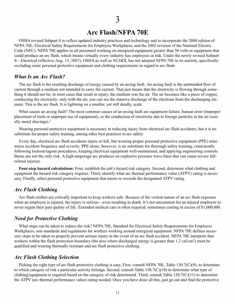
Arc Flash Clothing SelectionPicking the right type of arc flash protective clothing is easy. First, consult NFPA 70E, Table 130.7(C)(9), to determine
to which category of risk a particular activity belongs. Second, consult Table 130.7(C)(10) to determine what type of
clothing/equipment is required based on the category of risk determined. Third, consult Table 130.7(C)(11) to determine
the ATPV (arc thermal performance value) rating needed. Once you have done all this, just go out and find the protective
11

gear that meets or exceeds this rating.3 One thing to remember when picking the protective work wear is to try and ensure
that no skin is exposed. Ensure that the pant legs (if not connected to boots) completely go down to the boot. Also ensure
that the sleeves of the protective work wear go down to the hand, leaving none of the arm exposed. And lastly, remember
that the head is the most vulnerable part of the body. Do not forget to complete the arc flash protective clothing with suit-
able head gear of the same ATPV rating as the rest of the work-wear plus high voltage gloves.
NFPA 70E Table 130.7(C)(10) [2009 Edition]
Protective Clothing and Personal Protective Equipment (PPE)
12
Hazard/Risk Category Protective Clothing and PPE
Hazard/Risk Category 0
Protective Clothing, Nonmelting (according to ASTM F 1506-00) Shirt (long sleeve)
or Untreated Natural Fiber Pants (long)
FR Protective Equipment Safety glasses or safety goggles (SR)
Hearing protection (ear canal inserts)
Leather gloves (AN) (Note 2)
Hazard/Risk Category 1
FR Clothing, Minimum Arc Rating of 4 (Note 1) Arc-rated long-sleeve shirt (Note 3)
Arc-rated pants (Note 3)
Arc-rated coverall (Note 4)
Arc-rated face shield or arc flash suit hood (Note 7)
Arc-ratted jacket, parka, or rainwear (AN)
FR Protective Equipment Hard hat
Safety glasses or safety goggles (SR)
Hearing protection (ear canal inserts)
Leather gloves (Note 2)
Leather work shoes (AN)
Hazard/Risk Category 2
FR Clothing, Minimum Arc Rating of 8 (Note 1) Arc-rated long-sleeve shirt (Note 5)
Arc-rated pants (Note 5)
Arc-rated coverall (Note 6)
Arc-rated face shield or arc flash suit hood (Note 7)
Arc rated jacket, parka, or rainwear (AN)
FR Protective Equipment Hard hat
Safety glasses or safety goggles (SR)
Hearing protection (ear canal inserts)
Leather gloves (Note 2)
Leather work shoes
Hazard/Risk Category 2*
FR Clothing, Minimum Arc Rating of 8 (Note 1) Arc-rated long-sleeve shirt (Note 5)
Arc-rated pants (Note 5)
Arc-rated coverall (Note 6)
Arc-rated arc flash suit hood (Note 10)
Arc-rated jacket, parka, or rainwear (AN)
FR Protective Equipment Hard hat
Safety glasses or safety goggles (SR)
Hearing protection (ear canal inserts)
Leather gloves (Note 2)
Leather work shoes

13
NFPA 70E Table 130.7(C)(10) (continued)
Protective Clothing and Personal Protective Equipment (PPE) (continued)
Table 130.7(C)(10) lists the requirements for protective clothing and other protective equipment based on Hazard/Risk
Category numbers 0 through 4. This clothing and equipment shall be used when working within the Arc Flash Protection
Boundary.
Hazard/Risk Category Protective Clothing and PPE
Hazard/Risk Category 3
FR Clothing, Minimum Arc Rating of 25 (Note 1) Arc-rated long-sleeve shirt (AR) (Note 8)
Arc-rated pants (AR) (Note 8)
Arc-rated coverall (AR) (Note 8)
Arc-rated arc flash jack (AR) (Note 8)
Arc-rated arc flash suit pants (AR) (Note 8)
Arc-rated arc flash suit hood (Note 8)
Arc-rated jacket, parka, or rainwear (AN)
FR Protective Equipment Hard hat
FR hard hat liner (AR)
Safety glasses or safety goggles (SR)
Hearing protection (ear canal inserts)
Leather work shoes
Hazard/Risk Category 4
FR Clothing, Minimum Arc Rating of 40 (Note 1) Arc-rated long-sleeve shirt (AR) (Note 9)
Arc-rated pants (AR) (Note 9)
Arc-rated coverall (AR) (Note 9)
Arc-rated arc flash jack (AR) (Note 9)
Arc-rated arc flash suit pants (AR) (Note 9)
Arc-rated arc flash suit hood (Note 9)
Arc-rated jacket, parka, or rainwear (AN)
FR Protective Equipment Hard hat
FR hard hat liner (AR)
Safety glasses or safety goggles (SR)
Hearing protection (ear canal inserts)
Arc-rated gloves (Note 2)
Leather work shoes
AN = As needed
AR = As required
SR = Selection required
X = Minimum required
Notes:1. See Table 130.7(C)(11). Arc rating for a garment or system of garments is expressed in cal/cm2.2. If rubber insulating gloves with leather protectors are required by Table 130.7(C)(9), additional leather or arc-rated
gloves are not required. The combination of rubber insulating gloves with leather protectors satisfies the arc flashprotection requirement.
3. The FR shirt and pants used for Hazard /Risk Category 1 shall have a minimum arc rating of 4.4. Alternate is to use FR coveralls (minimum arc rating of 4) instead of FR shirt and FR pants.5. FR shirt and FR pants used for Hazard/Risk Category 2 shall have a minimum arc rating of 8.6. Alternate is to use FR coveralls (minimum arc rating of 8) instead of FR shirt and FR pants.7. A face shield with a minimum arc rating of 4 for Hazard/Risk Category 1 or a minimum arc rating of 8 for
Hazard/Risk Category 2, with wrap-around guarding to protect not only the face, but also the forehead, ears, andneck (or, alternatively, an arc-rated arc flash suit hood), is required.
8. An alternate is to use a total FR clothing system and hood, which shall have a minimum arc rating of 25 forHazard/Risk Category 3.
9. The total clothing system consisting of FR shirt and pants and/or FR coveralls and/or flash coat and pants and hoodshall have a minimum arc rating of 40 for Hazard/Risk Category 4.
10. Alternate is to use a face shield with a minimum arc rating of 8 and a balaclava (sock hood) with a minimum arc rat-ing of 8 and which covers the face, head and neck except for the eye and nose areas.

14
NFPA 70E Table 130.7(C)(11)6
Protective Clothing Characteristics
When nothing can be done about working within a flash protection boundary, proper arc flash protective clothing needs
to be worn. Workers need to remember that arc flash accidents do not only occur with equipment at high voltage. The
majority of arc flash accidents occur with low (120V) and medium voltage (480V) equipment. Workers who wear the
proper arc flash protective clothing will significantly reduce the risk of injury or death should an arc flash accident occur.
Summary (Flash Hazard Analysis)A complete electrical hazard analysis must also contain a Flash Hazard Analysis. NFPA 70E Article 130.3 requires this
analysis to be performed. “A Flash Hazard Analysis shall be done in order to protect personnel from the possibility ofbeing injured by an Arc-Flash. The analysis shall determine the Flash Protection Boundary and the personal protectiveequipment that people within the Flash Protection Boundary shall use.” NFPA 70E (2009 Edition) lists an exception at
Article 130.3 that an arc flash hazard analysis is not required where all of the following conditions exist: (1) The circuit israted 240 volts or less. (2) The circuit is supplied by one transformer. (3) The transformer supplying the circuit is ratedless than 125 kVA).
Appropriate safety-related work practices must be determined before any person is exposed to the electrical hazards
involved by using both shock hazard analysis and arc flash hazard analysis independently. Ensure a flash hazard analysis
is performed where appropriate and acquire appropriate flash retardant clothing (FRC). Care and laundering of FRC
should be performed carefully in accordance with garment instructions. Employers or employees must follow safe work
practices. Employees must be adequately trained on electrical safety and first aid/CPR where needed. Lock out all equip-
ment during maintenance and servicing whenever possible.
Hazard/Risk Clothing Description Required Minimum
Category Arc Rating of PPE
[J/cm2(cal/cm2)]
0 Nonmelting, flammable materials (i.e., untreated cotton, wool, or silk, or blends N/A
of these materials) with a fabric weigh at least 4.5 oz/yd2
1 Arc-rated FR shirt and FR pants or FR coverall 16.74 (4)
2 Arc-rated FR shirt and FR pants or FR coverall 33.47 (8)
3 Arc-rated FR shirt and pants or FR coverall, and arc flash suit selected so that 104.6 (25)
the system arc rating meets the required minimum
4 Arc-rated FR shirt and pants or FR coverall, and arc flash suit selected so that 167.36 (40)
the system arc rating meets the required minimum
Note: Arc rating is defined in Article 100 and can be either ATPV or EBT. ATPV is defined in ASTM F 1959, Standard TestMethod for Determining the Arc Thermal Performance Value of Materials for Clothing, as the incident energy on a materi-
al or a multilayer system of materials that results in a 50% probability that sufficient heat transfer through the tested
specimen is predicted to cause the onset of a second-degree skin burn injury based on the Stoll curve, cal/cm2. EBT is
defined in ASTM F 1959 as the incident energy on a material or material system that results in a 50% probability of
breakopen. Arc rating is reported as either ATPV or EBT, whichever is the lower value.
____________
6 NFPA 70E pg. 144

15
4
Electrical Safety ProgramEmployers must implement and document an overall electrical safety program that directs activity appropriate for the
voltage, energy level, and circuit conditions.
General Categories of Electrical HazardsThere are three general categories of electrical hazards: electrical shock, arc-flash, and arc-blast.
(1) Electric Shock. Approximately 30,000 nonfatal electrical shock accidents occur each year. The National Safety
Council estimates that about 1,000 fatalities each year are due to electrocution, more than half of them while servicing
energized systems of less than 600 volts. Electrocution is the fourth leading cause of industrial fatalities, after traffic,
homicide, and construction accidents. The current required to light a 71⁄2 watt, 120 volt lamp, if passed across the chest, is
enough to cause a fatality. The most damaging paths through the body are through the lungs, heart, and brain.
(2) Arc-Flash. When an electric current passes through air between ungrounded conductors or between ungrounded
conductors and grounded conductors, the temperatures can reach 35,000°F. Exposure to these extreme temperatures both
burns the skin directly and causes ignition of clothing, which adds to the burn injury. The majority of hospital admissions
due to electrical accidents are from arc-flash burns, not from shocks. Each year more than 2,000 people are admitted to
burn centers with severe arc-flash burns. Arc-flashes can and do kill at distances of 10 feet (3 m).
(3) Arc-Blast. The tremendous temperatures of the arc cause the explosive expansion of both the surrounding air and
the metal in the arc path. For example, stated in NFPA 70E (2009 edition), copper expands by a factor of 67,000 times
when it turns from a solid to a vapor. The danger associated with this expansion is one of high pressures, sound, and
shrapnel. The high pressures can easily exceed hundreds or even thousands of pounds per square foot, knocking workers
off ladders, rupturing eardrums, and collapsing lungs. The sounds associated with these pressures can exceed 160 dB.
Finally, material and molten metal is expelled away from the arc at speeds exceeding 1,600 km/hr (700 mph), fast enough
for shrapnel to completely penetrate the human body.
NFPA 70E Requirementsl Arc flash boundaries must be known l Electrically safe (voltage rated) toolsl Safe approach distances established and maintained l PPE (arc thermal performance value APTV)l Marking equipment relative to hazards l Training
Electrical Hazard AnalysisIf the energized electrical conductors or circuit parts operating at 50 volts or more are not placed in an electrically safe
work condition, other safety-related work practices shall be used to protect employees who might be exposed to the elec-
trical hazards involved. Appropriate safety-related work practices must be determined before any person is exposed to the
electrical hazards involved by using both shock hazard analysis and arc flash hazard analysis.
Shock Hazard Analysis. A shock hazard analysis must determine the voltage to which personnel will be exposed,
boundary requirements, and the personal protective equipment necessary in order to minimize the possibility of electrical
shock to personnel.
Arc Flash Hazard Analysis. An arc flash hazard analysis must determine the Arc Flash Protection Boundary and the
personal protective equipment that people within the Arc Flash Protection Boundary shall use.
The arc flash hazard analysis must be updated when a major modification or renovation takes place. It must be
reviewed periodically, not to exceed five years, to account for changes in the electrical distribution system that could
affect the results of the arc flash hazard analysis. The arc flash hazard analysis must take into consideration the design of
the overcurrent protective device and its opening time, including its condition of maintenance.

16
Exception #1: An arc flash hazard analysis is not required where all of the following conditions exist: (1) The circuit is rated 240 volts or less. (2) The circuit is supplied by one transformer. (3) The transformer supplying the circuit is rated less than 125 kVA.
Exception #2: The requirements of 130.7(C)(9), 130.7(C)(10), and 130.7(C)(11) must be permitted to be used in lieu ofa detailed incident energy analysis.
Arc Flash Protection Boundary
1. Voltage Levels Between 50 Volts and 600 Volts. In those cases where detailed arc flash hazard analysis calcula-
tions are not performed for systems that are between 50 volts and 600 volts, the Arc Flash Protection Boundary must
be 4.0 ft, based on the product of clearing time of 2 cycles (0.033 sec) and the available bolted fault current of 50 kA
or any combination not exceeding 100 kA cycles (1667 ampere seconds). When the product of clearing times and
bolted fault current exceeds 100 kA cycles, the Arc Flash Protection Boundary must be calculated.
2. Voltage Levels Above 600 Volts. At voltage levels above 600 volts, the Arc Flash Protection Boundary shall be the
distance at which the incident energy equals 5 J/cm2 (1.2 cal/cm2). For situations where fault-clearing time is equal
to or less than 0.1 sec, the Arc Flash Protection Boundary must be the distance at which the incident energy level
equals 6.24 J/cm2 (1.5 cal/cm2).
Approach Boundaries
NFPA 70E has established three shock protection boundaries:
1) Limited Approach Boundary2) Restricted Approach Boundary3) Prohibited Approach Boundary
Limited Approach Boundary
The limited approach boundary is an approach boundary to protect personnel from shock. A boundary distance is
established from an energized part based on system voltage. To enter this boundary, unqualified persons must be accom-
panied by a qualified person and use PPE.
Restricted Approach Boundary
The restricted approach boundary is an approach boundary to protect personnel from shock. A boundary distance is
established from an energized part based on system voltage. Only qualified persons are allowed in this boundary and they
must use PPE.
Prohibited Approach Boundary
The prohibited approach boundary is an approach boundary to protect personnel from shock. Work in this boundary is
considered the same as making direct contact with an energized part. Only qualified persons are allowed to enter this
boundary and they must use PPE.
Shock protection boundaries are based on system voltage and whether the exposed energized components are fixed or
movable.
Flash Hazard AnalysisA complete electrical hazard analysis must also contain a Flash Hazard Analysis. NFPA 70E Article 130.3 requires this
analysis to be performed: “A Flash Hazard Analysis shall be done in order to protect personnel from the possibility of
being injured by an Arc-Flash. The analysis shall determine the Flash Protection Boundary and the personal protective
equipment that people within the Flash Protection Boundary shall use.”
Unlike the Shock Hazard Protection Boundaries that are based solely on system voltage, the Flash Protection Boundary
is not fixed. In order to determine the potential Arc-Flash hazard, Flash Protection Boundaries must be calculated at every
point where service on energized equipment, devices, or conductors may be required.

17
Electric Shock Boundaries
To Live Parts for 300–600 Volts
Prohibited Approach Boundary Restricted Approach Boundary Limited Approach Boundary
1 in. 1 ft. 3 ft. 6 in.
Power source g
Flash Protection Boundary
For Live Parts For 300–600 Volts
Flash Protection Boundary
4 ft.
Power source g
To protect against burns, there is one more boundary:
The flash pro tection boundary is where PPE is needed to
prevent incurable burns, if there is an arc flash.
Summary of Approach BoundariesThe risk from exposed live parts depends on your distance from the parts. Three “boundaries” are key to protecting
yourself from elec tric shock and one to protect you from arc flashes or blasts. These boundaries are set by the National
Fire Protection Association (NFPA 70E).
The limited approach boundary is the closest an unqualified per son can approach, unless a qualified person accom-
panies you. A qualified person is someone who has received mandated training on the hazards and on the construction
and operation of equipment involved in a task.
The restricted approach boundary is the closest to exposed live parts that a qualified person can go without proper
PPE (such as, flame-resistant clothing) and insulated tools. When you are this close, if you move the wrong way, you or
your tools could touch live parts.
The prohibited approach boundary—the most serious—is the dis tance you must stay from exposed live parts to pre-
vent flashover or arcing in air. Get any closer and it is like direct contact with a live part.

18
OSHA Standards Enforced by NCDOL related to employee protection from hazards of arc flash
1910.333—Selection and use of work practices
(a) General. Safety-related work practices shall be employed to prevent electric shock or other injuries resulting from
either direct or indirect electrical contacts, when work is performed near or on equipment or circuits which are or may be
energized. The specific safety-related work practices shall be consistent with the nature and extent of the associated elec-
trical hazards.
(2) Energized parts. If the exposed live parts are not deenergized (i.e., for reasons of increased or additional hazards or
infeasibility), other safety-related work practices shall be used to protect employees who may be exposed to the electrical
hazards involved. Such work practices shall protect employees against contact with energized circuit parts directly with
any part of their body or indirectly through some other conductive object. The work practices that are used shall be suit-
able for the conditions under which the work is to be performed and for the voltage level of the exposed electric conduc-
tors or circuit parts. Specific work practice requirements are detailed in paragraph (c) of this section.
[1910.333(b) “Working on or near exposed deenergized parts.”]
(c) Working on or near exposed energized parts.
(1) Application. This paragraph applies to work performed on exposed live parts (involving either direct contact or by
means of tools or materials) or near enough to them for employees to be exposed to any hazard they present.
(2) Work on energized equipment. Only qualified persons may work on electric circuit parts or equipment that have not
been deenergized under the procedures of paragraph (b) of this section. Such persons shall be capable of working safely
on energized circuits and shall be familiar with the proper use of special precautionary techniques, personal protective
equipment, insulating and shielding materials, and insulated tools.
1910.335—Safeguards for personnel protection
(a) Use of protective equipment.
(1) Personal protective equipment.
(i) Employees working in areas where there are potential electrical hazards shall be provided with, and shall use, electrical
protective equipment that is appropriate for the specific parts of the body to be protected and for the work to be performed.
Note: Personal protective equipment requirements are contained in Subpart I of this part.
(ii) Protective equipment shall be maintained in a safe, reliable condition and shall be periodically inspected or tested, as
required by §1910.137.
(2) General protective equipment and tools.
(i) When working near exposed energized conductors or circuit parts, each employee shall use insulated tools or handling
equipment if the tools or handling equipment might make contact with such conductors or parts. If the insulating capability
of insulated tools or handling equipment is subject to damage, the insulating material shall be protected.
The General Duty Clause
General Duty Requirement. NCGS 95-129(1) requires that “Each employer will furnish to each of his employees condi-
tions of employment and a place of employment that are free from recognized hazards that are causing or are likely to
cause death or serious physical harm to his employees.”

19
PPE REQUIREMENTS
Hazard Risk Required Minimum INCIDENT Typical Protective Clothing Systems Minimum
Category Arc-Rating of PPE ENERGY Clothing Description Flash
(cal/cm2) (cal/cm2) Protection
FR Protective Equipment Boundary (in.)
0 N/A 0 to 1.2 1 layer of non-melting, flammable 6
fabric with weight of at least 4.5 oz/yd2
Safety glasses or safety goggles (SR);
Hearing protection (ear canal inserts);
Leather gloves (AN)
1 4 1.21 to 4 1 layer of Arc-rated FR shirt and FR 15
pants or FR coverall
Hard hat; Safety glasses or safety
goggles (SR); Hearing protection (ear
canal inserts); Leather gloves; Leather
work shoes (AN)
2 8 4.1 to 8 1 or 2 layers of Arc-rated FR shirt and 45
FR pants with conventional cotton
underwear
Hard hat; Safety glasses or safety
goggles (SR); Hearing protection (ear
canal inserts); Leather gloves; Leather
work shoes
3 25 8.1 to 25 2 or 3 layers of Arc-rated FR shirt, 60
FR pants plus FR coverall cotton
underwear
Hard hat; FR hard hat liner (AR;
Safety glasses or safety goggles (SR);
Hearing protection (ear canal inserts);
Arc-rated gloves; Leather work shoes
4 40 25.1 to 40 3 or more layers of Arc-rated FR shirt,
FR pants plus multi-layer flash suit 120
Hard hat; FR hard hat liner (AR;
Safety glasses or safety goggles (SR);
Hearing protection (ear canal inserts);
Arc-rated gloves; Leather work shoes
Derived from NFPA 70E Table 130.7(C)(10) & (C)(11)
AN = As needed (optional) / AR = As required / SR = Selection required
ARC-FLASH METRICS
Energy (E) = Power (P) x Time (t)
Power (P) = Volts (V) x Amps (I)
Calories (E) = Volts (V) x Amps (I) x Time (t)
1 Calorie = 4,1869 watt-seconds
1 Joule = 1 watt-second
A Calorie is the amount of heat energyneeded to raise the temperature of one gramof water by one degree Celsius.

20
�/&
*�$
+�$
*�$
012&��3
0(4$53
0�� ����677� ��$5& ��178 �
�$�23
�786 '�/$64�677� �
�786 '/$64�
�
5
Ground-Fault Circuit Protection
Circuit Protection DevicesCircuit protection devices are designed to automatically limit or shut off the flow of electricity in the event of a
ground-fault, overload or short circuit in the wiring system. Fuses, circuit breakers and ground-fault circuit interrupters
are three well-known examples of such devices.
Fuses and circuit-breakers are over-current devices that are placed in circuits to monitor the amount of current that the
circuit will carry. They automatically open or break the circuit when the amount of current flow becomes excessive and
therefore unsafe. Fuses are designed to melt when too much current flows through them. Circuit breakers, on the other
hand, are designed to trip open the circuit by electromechanical means. Fuses and circuit breakers are intended primarily
for the protection of conductors and equipment. They prevent overheating of wires and components that might otherwise
create hazards for operators. They also open the circuit under certain hazardous ground-fault conditions.
The ground-fault circuit interrupter, or GFCI, is designed to shut off electric power within as little as one-fortieth of a sec-
ond. It works by comparing the amount of current going to electric equipment against the amount of current returning from
the equipment along the circuit conductors. If the current difference exceeds 6 milliamperes, the GFCI interrupts the current
quickly enough to prevent electrocution. The GFCI is used in high-risk areas such as wet locations and construction sites.
The GFCI contains a special sensor that monitors the strength of the magnetic field around each wire in the circuit
when current is flowing. The magnetic field around a wire is directly proportional to the amount of current flow, thus the
circuitry can accurately translate the magnetic information into current flow.
If the current flowing in the black (ungrounded) wire is within 5 (± 1) milliamperes of the current flowing in the white
(grounded) wire at any given instant, the circuitry considers the situation normal. All the current is flowing in the normal
path. If, however, the current flow in the two wires differs by more than 5 milliamperes, the GFCI will quickly open the
circuit. This is illustrated in the Figure 4.
Figure 4
How the GFCI Protects People(By Opening the Circuit When Current Flows Through a Ground-Fault Path)
21
Note that the GFCI will open the circuit if 5 milliamperes or more of current returns to the service entrance by any path
other than the intended white (grounded) conductor. If the equipment grounding conductor is properly installed and main-
tained, this will happen as soon as the faulty tool is plugged in. If by chance this grounding conductor is not intact and of
low-impedance, the GFCI may not trip out until a person provides a path. In this case, the person will receive a shock, but
the GFCI should trip out so quickly that the shock will not be harmful.
Safe Work PracticesEmployees and others working with electric equipment need to use safe work practices. These include deenergizing
electric equipment before inspecting or making repairs, using electric tools that are in good repair, using good judgment
when working near energized lines, and using appropriate protective equipment. Electrical safety-related work practice
requirements are contained in Subpart S of 29 CFR Part 1910, in sections 1910.331–1910.335.
TrainingTo ensure that they use safe work practices, employees must be aware of the electrical hazards to which they will be
exposed. Employees must be trained in safety-related work practices as well as any other procedures necessary for safety
from electrical hazards.
Polarity of Connectionsl No grounded conductor may be attached to any terminal or lead so as to reverse designated polarity.
l A grounding terminal or grounding-type device on a receptacle, cord connector or attachment plug may not be used
for purposes other than grounding.
The above two subparagraphs dealing with polarity of connections and use of grounding terminals and devices address
one potentially dangerous aspect of alternating current: many pieces of equipment will operate properly even though the
supply wires are not connected in the order designated by design or the manufacturer. Improper connection of these con-
ductors is most prevalent on the smaller branch circuit typically associated with standard 120 volt receptacle outlets,
lighting fixtures, and cord- and plug-connected equipment. When plugs, receptacles and connectors are used in an electri-
cal branch circuit, correct polarity between the ungrounded (hot) conductor, the grounded (neutral) conductor and the
grounding conductor must be maintained.
Reversed polarity is a condition when the identified circuit conductor (the grounded conductor or neutral) is incorrectly
connected to the ungrounded or hot terminal of a plug, receptacle or other type of connector. Correct polarity is achieved
when the grounded conductor is connected to the corresponding grounded terminal and the ungrounded conductor is con-
nected to the corresponding ungrounded terminal. The reverse of the designated polarity is prohibited. Figure 5 illustrates
a duplex receptacle correctly wired. Terminals are designated and identified to avoid confusion. An easy way to remem-
ber the correct polarity is “white to light”—the white (grounded) wire should be connected to the light or nickel-colored
terminal; “black to brass”—the black or multi-colored (ungrounded) wire should be connected to the brass terminal; and
“green to green”—the green or bare (grounding) wire should be connected to the green hexagonal head terminal screw.

Figure 5
Duplex Receptacle Correctly Wired to Designated Terminals
Deenergizing Electrical Equipment. The accidental or unexpected sudden starting of electrical equipment can cause
severe injury or death. Before any inspections or repairs are made—even on low-voltage circuits—the current must be
turned off at the switchbox and the switch padlocked in the “off” position. At the same time, the switch or controls of the
machine or other equipment being locked out of service must be securely tagged to show which equipment or circuits are
being worked on.
Maintenance employees should be qualified electricians who have been well instructed in lockout procedures. No two
locks should be alike; each key should fit only one lock, and only one key should be issued to each maintenance employ-
ee. If more than one employee is repairing a piece of equipment, each should lock out the switch with his or her own lock
and never permit anyone else to remove it. The maintenance worker should at all times be certain that he or she is not
exposing other employees to danger.
Overhead LinesIf work is to be performed near overhead power lines, the lines must be deenergized and grounded by the owner or
operator of the lines, or other protective measures must be provided before work is started. Protective measures (such as
guarding or insulating the lines) must be designed to prevent employees from contacting the lines.
Unqualified employees and mechanical equipment must stay at least 10 feet (3.05 meters) away from overhead power
lines. If the voltage is more than 50,000 volts, the clearance must be increased by 4 inches (10 centimeters) for each addi-
tional 10,000 volts.
When mechanical equipment is being operated near overhead lines, employees standing on the ground may not contact the
equipment unless it is located so that the required clearance cannot be violated even at the maximum reach of the equipment.
Protective Equipment. Employees whose occupations require them to work directly with electricity must use the per-
sonal protective equipment required for the jobs they perform. This equipment may consist of rubber insulating gloves,
hoods, sleeves, matting, blankets, line hose and industrial protective helmets.
22
�������������8������
��������������8������
6��������������8������
1!���1���
(��91���
���������(�������������������
�9������4��!�����������������
(����%���������������
������2�:�������2����������������
23
Tools. To maximize his or her own safety, an employee should always use tools that work properly. Tools must be
inspected before use, and those found questionable, removed from service and properly tagged. Tools and other equip-
ment should be regularly maintained. Inadequate maintenance can cause equipment to deteriorate, resulting in an unsafe
condition. Tools that are used by employees to handle energized conductors must be designed and constructed to with-
stand the voltages and stresses to which they are exposed.
Good Judgment. Perhaps the single most successful defense against electrical accidents is the continuous exercising of
good judgment or common sense. All employees should be thoroughly familiar with the safety procedures for their partic-
ular jobs. When work is performed on electrical equipment, for example, some basic procedures are:
1. Have the equipment deenergized.
2. Ensure that the equipment remains deenergized by using some type of lockout and tag procedure.
3. Use insulating protective equipment.
4. Keep a safe distance from energized parts.
Protection is generally available as a GFCI/circuit breaker or GFCI receptacle. The breaker has a ground fault sensing
circuit breaker body. The same breaker or interrupting mechanism is used for both ground faults and overloads. GFCI
receptacles are located at the point of use; the receptacle opens the circuit.
Insulation and Grounding DeficienciesInsulation and grounding are two recognized means of preventing injury during electrical equipment operation.
Conductor insulation may be provided by placing nonconductive material such as plastic around the conductor.
Grounding may be achieved through the use of a direct connection to a known ground such as a metal cold water pipe.
Consider, for example, the metal housing or enclosure around a motor or the metal box in which electrical switches,
circuit breakers and controls are placed. Such enclosures protect the equipment from dirt and moisture and prevent acci-
dental contact with exposed wiring; however, there is a hazard associated with housings and enclosures. A malfunction
within the equipment—such as deteriorated insulation—may create an electric shock hazard. Many metal enclosures are
connected to a ground to eliminate the hazard. If an energized wire contacts a grounded enclosure, a ground fault results,
which normally will trip a circuit breaker, blow a fuse or trip a GFCI. Metal enclosures and containers are usually ground-
ed by connecting them with a wire going to the ground. This wire is called an equipment grounding conductor. Most
portable electric tools and appliances are grounded by this means. There is one disadvantage to grounding: a break in the
grounding system may occur without the user’s knowledge, thus producing an unsuspected hazard.
Insulation may be damaged by hard usage on the job or by aging. If this damage causes the conductors to become
exposed, the hazards of shocks, burns, and fire will exist. Double insulation may be used as additional protection on the
live parts of a tool, but double insulation does not provide protection against defective cords and plugs or against heavy
moisture conditions.
The use of a ground-fault circuit interrupter is one method used to overcome grounding and insulation deficiencies.
GFCI Operation PrincipleIn most cases, insulation and grounding are used to prevent injury from electrical wiring systems or equipment. However,
there are instances when these recognized methods do not provide the degree of protection required. To help appreciate this,
let’s consider a few examples of where ground fault circuit interrupters would provide additional protection.
Many portable hand tools, such as electric drills, are now manufactured with non-metallic cases. If approved, we refer to
such tools as double insulated. Although this design method assists in reducing the risk from grounding deficiencies, a shock
hazard can still exist. In many cases, people must use such electrical equipment where there is considerable moisture or wet-
ness. Although the person is insulated from the electrical wiring and components, there is still the possibility that water can
enter the tool housing. Ordinary water is a conductor of electricity. Therefore, if the water contacts energized parts, a path
will be provided from inside the housing to the outside, bypassing the double insulation. When a person holding a hand tool
under these conditions touches another conductive surface in the work environment, an electric shock will result.
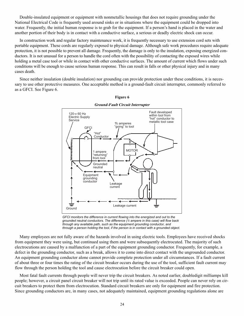
24
Double-insulated equipment or equipment with nonmetallic housings that does not require grounding under the
National Electrical Code is frequently used around sinks or in situations where the equipment could be dropped into
water. Frequently, the initial human response is to grab for the equipment. If a person’s hand is placed in the water and
another portion of their body is in contact with a conductive surface, a serious or deadly electric shock can occur.
In construction work and regular factory maintenance work, it is frequently necessary to use extension cord sets with
portable equipment. These cords are regularly exposed to physical damage. Although safe work procedures require adequate
protection, it is not possible to prevent all damage. Frequently, the damage is only to the insulation, exposing energized con-
ductors. It is not unusual for a person to handle the cord often with the possibility of contacting the exposed wires while
holding a metal case tool or while in contact with other conductive surfaces. The amount of current which flows under such
conditions will be enough to cause serious human response. This can result in falls or other physical injury and in many
cases death.
Since neither insulation (double insulation) nor grounding can provide protection under these conditions, it is neces-
sary to use other protective measures. One acceptable method is a ground-fault circuit interrupter, commonly referred to
as a GFCI. See Figure 6.
Figure 6
Ground-Fault Circuit Interrupter
Many employees are not fully aware of the hazards involved in using electric tools. Employees have received shocks
from equipment they were using, but continued using them and were subsequently electrocuted. The majority of such
electrocutions are caused by a malfunction of a part of the equipment grounding conductor. Frequently, for example, a
defect in the grounding conductor, such as a break, allows it to come into direct contact with the ungrounded conductor.
An equipment grounding conductor alone cannot provide complete protection under all circumstances. If a fault current
of about three or four times the rating of the circuit breaker occurs during the use of the tool, sufficient fault current may
flow through the person holding the tool and cause electrocution before the circuit breaker could open.
Most fatal fault currents through people will never trip the circuit breakers. As noted earlier, doubledigit milliamps kill
people; however, a circuit panel circuit breaker will not trip until its rated value is exceeded. People can never rely on cir-
cuit breakers to protect them from electrocution. Standard circuit breakers are only for equipment and fire protection.
Since grounding conductors are, in many cases, not adequately maintained, equipment grounding regulations alone are
-)+%��;+�2"�������������������
�/&
<2��=�������
-->)��������<�����=��������
/�����������������!������������<!��=���������������������������
-�������<���������=���������
���������������
�������������������������
������
4��9���������
4��9����������
�8�87
GFCI monitors the difference in current flowing into the energized and out to thegrounded neutral conductors. The difference (1/2 ampere in this case) will flow backthrough any available path, such as the equipment grounding conductor, andthrough a person holding the tool, if the person is in contact with a grounded object.
25
inadequate to provide necessary protection. Accordingly, there is a need to supplement the existing equipment grounding
conductor requirements to protect employees from ground fault accidents resulting in injuries and fatalities.
The GFCI will not protect the employee from line-to-line contact hazards (such as a person holding two energized wires
or an energized and a neutral wire in each hand). It does provide protection against the most common form of electrical
shock hazard—the ground fault. It also provides protection against fires, overheating and destruction of insulation on wiring.
Flexible Electrical Cords—Another Reason for Added Protection
With the wide use of portable tools, the use of flexible cords often becomes necessary. Hazards are created when cords,
cord connectors, receptacles, and cord- and plug-connected equipment are improperly used and maintained, or are used in
a hazardous environment (such as around water).
Generally, flexible cords are more vulnerable to damage than is fixed wiring. Flexible cords must be so connected to
devices and to fittings as to prevent tension at joints and terminal screws. Because a cord is exposed, flexible and unse-
cured, joints and terminals become more vulnerable. Flexible cord conductors are finely stranded for flexibility, but the
strands of one conductor may loosen from under terminal screws and touch another conductor, especially if the cord is
subjected to stress or strain.
A flexible cord may be damaged by normal activities, by door or window edges, by staples or fastenings, by abrasion
from adjacent materials, by high temperature, or by aging. If the electrical conductors become exposed, there is danger of
shocks, burns or fire.
When a cord connector is wet, hazardous leakage can occur to the equipment grounding conductor and to humans who
pick up that connector if they also provide a path to ground. Such leakage is not limited to the face of the connector but
also develops at any wetted portion of it.
When the leakage current of tools is below 1 ampere and the grounding conductor has a low resistance, no shock
should be perceived. Should the resistance of the equipment grounding conductor increase, the current through the body
will also increase; thus, if the resistance of the equipment grounding conductor is significantly greater than 1 ohm, tools
with even small leakages become hazardous.
GFCIs can be used successfully to reduce electrical hazards on construction sites. Tripping of GFCIs—interruption of
current flow—is sometimes caused by wet connectors and tools. It is good practice to limit exposure of connectors and
tools to excessive moisture by using watertight or sealable connectors. Providing more GFCIs or shorter circuits can pre-
vent tripping caused by the cumulative leakage from several tools or by leakages from extremely long circuits.
Discussion of the OSHA StandardFollowing is a discussion of the major aspects of OSHA standard 29 CFR 1926.404(b)(1) for GFCIs. Employers are
required by the standard to use either ground-fault circuit interrupters as specified in paragraph (b)(1)(ii) or an assured
equipment grounding conductor program as specified in paragraph (b)(1)(iii), to protect employees on construction sites.
These requirements are in addition to any other requirements for equipment grounding conductors. Each method is dis-
cussed separately.
Ground-Fault Circuit Interrupters
The employer must provide GFCI protection for all 120-volt, 15- and 20-ampere, single-phase receptacles on construc-
tion sites that are not a part of the permanent wiring of the building or structure and which are in use by employees. As
noted, this protection is required in addition to, not in lieu of, the equipment grounding conductor requirements of 29
CFR 1926.
The GFCIs used must be approved, as that term is defined by OSHA. Various types of approved GFCIs suitable for use
on construction sites are available, including circuit-breaker, receptacle and portable types. Most of today’s approved
GFCIs have trip levels of 5 milliamperes ± 1 milliamperes. Portable GFCIs are acceptable if they are connected to the
receptacle outlet in use.
On generators where the supply wires are not required to be grounded, and are in fact not grounded, the return path for
a ground-fault current to flow is not completed, and the hazard that a GFCI would protect against is not present.
Consequently, the rule does not require the use of GFCIs on portable or vehiclemounted generators of 5 kilowatts capaci-
ty or less if the output is a two-wire, single-phase system and their circuit conductors are insulated from the generator

26
frame and all other grounded surfaces. It should be noted that receptacles on all small portable generators are not exempt
from the GFCI requirements. The standard clearly states that receptacles on such generators must have the circuit conduc-
tors insulated from the generator frames and all grounded surfaces to be exempt.
Assured Equipment Grounding Conductor Program
If the employer selects this option, the employer must provide an assured equipment grounding conductor program
covering all cord sets, receptacles that are not a part of the permanent wiring of the building or structure, and equipment
connected by cord and plug that is available for use by employees. Though it is not required to be posted, a written proce-
dure for the program must be kept at the jobsite and made available to the Occupational Safety and Health Division and
any affected employee.
The employer must designate one or more competent people to implement the program. A competent person is defined
in 29 CFR 1926.32(f) as one who is capable of identifying existing and predictable hazards in the surroundings or work-
ing conditions which are unsanitary, hazardous or dangerous to employees, and who has authorization to take prompt cor-
rective measures to eliminate them. This person may be the employer, an employee of the employer or another person.
Inspections
Equipment, except cord sets and receptacles that are fixed and not exposed to damage, must be inspected for visible
damage or defects before each day’s use. Examples of possible damage would be deformed or missing pins, insulation
damage, or indications of possible internal damage. Any equipment found to be damaged or defective may not be made
available for use or used by employees.
Periodic Tests
Two tests are required to be performed to ensure the safe condition of the equipment grounding conductor. The first test is a
continuity test—the equipment grounding conductor must be electrically continuous. This test is required to be performed on
all cord sets, receptacles that are not a part of the permanent wiring of the building or structure, and cord- and plug-connected
equipment that is required to be grounded. It may be performed by an ohmmeter for cord sets and cord- and plug-connected
equipment and by a receptacle tester for receptacles or by any other testing device that can ascertain electrical continuity.
In addition to the continuity test, a test must be performed on receptacles and attachment caps and plugs to ascertain
that the equipment grounding conductor is connected to its proper terminal. This test can be performed by the same
equipment used to perform the first test.
Both of these tests are required to be performed: (1) before first use, (2) after any repairs, (3) after damage can be rea-
sonably suspected to have occurred and (4) at three-month intervals. For cord sets and receptacles that are fixed and not
exposed to damage that rough handling or abuse is most likely to cause, the testing frequency may be reduced to once
every six months. The basis for the different testing interval is that this latter type of equipment, once it is in place, is not
subject to the same abuse, and the hazards thereby created, as equipment that is constantly moved around on construction
sites. Cord sets that we would consider fixed would only be those which, once they are put in place, remain stationary and
not those cord sets that are being constantly moved around on construction sites.
Recording of Testing
The testing must be recorded. To record the tests, color coding, logs or other effective means may be used. The record
must indicate which equipment passed the test and the date it was tested or the interval for which it was tested. Any
equipment that fails to pass the required tests may not be made available for use by employees until the defect has been
repaired and the equipment successfully retested.
The NEC also requires GFCI protection for residential bathrooms and outdoor receptacles, construction sites, and elec-
trical equipment on swimming pools (and between 10 and 15 feet of pools and in underwater lighting). In addition, any
other place where a hazardous condition might develop should have GFCI protection.
Specific Standard Requirements
All 120-volt, single-phase, 15- and 20-ampere receptacle outlets on construction sites that are not a part of the perma-
nent wiring of the building or structure and which are in use by employees must have approved GFCIs for protection of
personnel. Receptacles on a two-wire, single-phase portable or vehiclemounted generator rated not more than 5 kilowatts,
where the circuit conductors of the generator are insulated from the generator frame and all other grounded surfaces, need

27
not be protected with groundfault circuit interrupters. The employer must establish and implement an assured equipment
grounding conductor program on construction sites covering all cord sets, receptacles that are not a part of the permanent
wiring of the building or structure, and equipment connected by cord and plug that is available for use or used by employ-
ees. This program must comply with the following minimum requirements:
1. A written description of the program, including the specific procedures adopted by the employer, must be available
at the jobsite for inspection and copying by OSHA and by any affected employee.
2. The employer must designate one or more competent people (as defined by OSHA) to implement the program.
3. Each cord set, attachment cap, plug and receptacle of cord sets, and any equipment connected by cord and plug,
except cord sets and receptacles that are fixed and are not exposed to damage, must be visually inspected before
each day’s use for external defects, such as deformed or missing pins or insulation damage, and for indication of
possible internal damage. Equipment found damaged or defective may not be used until repaired.
4. The following tests must be performed on all cord sets, receptacles that are not a part of the permanent wiring of the
building or structure, and cord and plug-connected equipment required to be grounded:
a. All equipment grounding conductors must be tested for continuity and must be electrically continuous.
b. Each receptacle and attachment cap or plug must be tested for correct attachment of the equipment grounding
conductor. The equipment grounding conductor must be connected to its proper terminal.
5. All required tests must be performed:
a. Before first use
b. Before equipment is returned to service following any repairs
c. Before equipment is used after any incident that can be reasonably suspected to have caused damage (for exam-
ple, when a cord set is run over) and
d. At intervals, not to exceed three months, except that cord sets and receptacles that are fixed and not exposed to
damage must be tested at intervals not exceeding six months
6. The employer may not make available or permit the use by employees of any equipment that has not met these
requirements.
7. Tests performed as required must be recorded. This test record must identify each receptacle, cord set, and cord- and
plug-connected equipment that passed the test and must indicate the last date it was tested or the interval for which it
was tested. This record must be kept by means of logs, color coding or other effective means and must be main-
tained until replaced by a more current record. The record must be made available on the jobsite for inspection by
the Occupational Safety and Health Division and by any affected employee.
Program Evaluation
In evaluating an assured equipment grounding conductor program method of ground-fault protection, at least the items
listed below must be considered. All of these items are necessary for an effective assured equipment grounding conductor
program, and the weakness or absence of any specific item may make the program ineffective and unacceptable.
1. The program must cover all cord sets, receptacles (not part of permanent wiring), and cord- and plug-connected
equipment available for use by the employees.
2. There must be a written description of the program, including specific details, present at the jobsite. This program
must represent what is actually being carried out.
3. A competent person or people must be responsible for implementing the program. One person may have the overall
responsibility for the program and the actual cord and equipment testing and recording for several sites, while other com-
petent persons may conduct daily visual inspections and remove questionable or unsafe equipment from service on each
individual site.
4. A competent person must conduct visual inspections and carry out procedures intended to prevent the use of dam-
aged or defective tools.
5. Appropriate test equipment and procedures must be used in conducting the continuity tests and the wiring attach-
ment evaluations of the equipment grounding conductors on cords, plugs and temporary receptacles.

28
6. Appropriate test intervals must be established in accordance with the provisions of the standards and additional tests
must be made following suspected damage before returning repaired cords or equipment to service and before first use of
a new cord or tool.
7. Effective procedures or policies must be instituted to prevent the use of untested cords and equipment on the site.
8. An effective method of recordkeeping and identification of equipment and test intervals must be established. The
methods may range from detailed records to a simple color coding system with the code being included in the written pro-
gram.
Summary
Electrical hazards represent a serious, widespread occupational danger; practically all members of the workforce are
exposed to electrical energy during the performance of their daily duties, and electrocutions occur to workers in various
job categories. Many workers are unaware of the potential electrical hazards present in their work environment, which
makes them more vulnerable to the danger of electrocution.
The Occupational Safety and Health Administration addresses electrical safety in Subpart S, 29 CFR 1910.302 through
1910.399 of the General Industry Safety and Health Standards. The standards contain requirements that apply to all
electrical installations and utilization equipment, regardless of when they were designed or installed. Subpart K of 29
CFR 1926.402 through 1926.408 of the OSHA Construction Safety and Health Standards contain installation safety
requirements for electrical equipment and installations used to provide electric power and light at the jobsite. These
sections apply to both temporary and permanent installations used on the jobsite.
The National Electrical Code and the National Electrical Safety Code comprehensively address electrical safety
regulations. The purpose of the NEC is the practical safeguarding of people and property from hazards arising from the
use of electricity. The NEC contains provisions considered necessary for safety and applies to the installation of electric
conductors and equipment within or on public or private buildings or other structures, including mobile homes, recre-
ational vehicles and floating buildings; and other premises such as yards; carnival, parking and other lots; and industrial
substations. The NEC serves as the basis for electrical building codes across the United States.
The NESC contains rules necessary for the practical safeguarding of people during the installation, operation or main-
tenance of electric supply and communication lines and associated equipment. These rules contain the basic provisions
that are considered necessary for the safety of employees and the public under the specified conditions. Unlike the NEC,
the NESC contains work rules in addition to installation requirements.
Controlling electrical hazards is an important part of every safety and health program. The measures suggested in
this booklet should be of help in establishing such a program of control. The responsibility for this program should be
delegated to individuals who have a complete knowledge of electricity, electrical work practices and the appropriate
OSHA standards.

6
OSHA Standards Related to Lockout/Tagoutor the Control of Energy During Maintenance
The information below was adapted from standards promulgated under the federal Occupational Safety and Health
Act. The information relates each standard as it applies to lockout/tagout or the control of electrical energy during mainte-
nance. (It does not attempt to quote each standard verbatim or relate each standard in its entirety.) Consult the standard for
specific language.
The standards were first published in the Federal Register, then codified in the Code of Federal Regulations. Each
standard was adopted through the Occupational Safety and Health Act of North Carolina. The standards can be found in
OSHA Standards for General Industry and OSHA Standards for the Construction Industry. For copies of the standards,
consult the Education, Training and Technical Assistance Bureau, Occupational Safety and Health Division, N.C.
Department of Labor (see the inside back cover of this publication for the address and telephone number).
General IndustryGeneral
29 CFR 1910.147. This standard covers the servicing and maintenance of machines and equipment in which the unex-
pected energization or start up of the machines or equipment or release of stored energy could cause injury to employees.
This standard establishes minimum performance requirements for the control of such hazardous energy.
Note: This standard helps safeguard employees from the unexpected startup of machines or equipment or release of
hazardous energy while they are performing servicing or maintenance. The standard identifies the practices and proce-
dures necessary to shut down and lock out or tag out machines and equipment, requires that employees receive training in
their role in the lockout/tagout program, and mandates that periodic inspections be conducted to maintain or enhance the
energy control program.
Accident Prevention Signs and Tags
29 CFR 1910.145(f)(1). The tags are a temporary means of warning all concerned of a hazardous condition, defective
equipment, radiation hazards, etc. The tags are not to be considered as a complete warning method, but should be used
until a positive means can be employed to eliminate the hazard; for example, a “Do Not Start” tag on power equipment
shall be used for a few moments or a very short time until the switch in the system can be locked out; a “Defective
Equipment” tag shall be placed on a damaged ladder and immediate arrangements made for the ladder to be taken out of
service and sent to the repair shop.
29 CFR 1910.145(f)(3). Use. Tags shall be used as a means to prevent accidental injury or illness to employees who
are exposed to hazardous or potentially hazardous conditions, equipment or operations which are out of the ordinary,
unexpected, or not readily apparent. Tags shall be used until such time as the identified hazardous operation is completed.
29 CFR 1910.145(f)(5). Danger Tags. Danger tags shall be used in major hazard situations where an immediate hazard
presents a threat of death or serious injury to employees.
29 CFR 1910.145(f)(6). Caution Tags. Caution tags should be used only to warn against potential hazards or to caution
against unsafe practices.
Powered Industrial Trucks
29 CFR 1910.178(q)(4). Trucks in need of repairs to the electrical system shall have the battery disconnected prior to
such repairs.
Overhead and Gantry Cranes
29 CFR 1910.179(g)(5)(i). The power supply to the runway conductors shall be controlled by a switch or circuit break-
er located on a fixed structure, accessible from the floor and arranged to be locked in the open position.
29

30
29 CFR 1910.179(g)(5)(ii). On cab-operated cranes a switch or circuit breaker of the enclosed type, with provision for
locking in the open position, shall be provided in the leads from the runway conductors. A means of opening this switch
or circuit breaker shall be located within easy reach of the operator.
29 CFR 1910.179(g)(5)(iii). On floor-operated cranes, a switch or circuit breaker of the enclosed type, with provision
for locking in the open position, shall be provided in the leads from runway conductors. This disconnect shall be mounted
on the bridge or footwalk near the runway collectors. [See the provision for acceptable types of floor-operated discon-
nects.]
29 CFR 1910.179(l)(2)(i). Before adjustments and repairs are started on a crane the following precautions shall be
taken:
(b) All controllers shall be at the off position.
(c) The main or emergency switch shall be open and locked in the open position.
(d) Warning or “out of order” signs shall be placed on the crane, also on the floor beneath or on the hook where
visible from the floor.
Derricks
29 CFR 1910.181(f)(2)(i). Maintenance procedure. Before adjustments and repairs are started on a derrick, the follow-
ing precautions shall be taken:
(a) The derrick to be repaired shall be arranged so it will cause the least interference with other equipment and
operations in the area.
(c) The main or emergency switch shall be locked in the open position, if an electric hoist is used.
(d) Warning or “out of order” signs shall be placed on the derrick and hoist.
Woodworking Machinery Requirements
29 CFR 1910.213(a)(10). It is recommended that each power-driven wood working machine be provided with a dis-
connect switch that can be locked in the off position.
29 CFR 1910.213(b)(3). On applications where injury to the operator might result if motors were to restart after power
failures, provision shall be made to prevent machines from automatically restarting upon restoration of power.
29 CFR 1910.213(b)(5). On each machine operated by electric motors, positive means shall be provided for rendering
such controls or devices inoperative while repairs or adjustments are being made to the machines they control.
Mechanical Power Presses
29 CFR 1910.217(b)(8)(i). A main power disconnect switch capable of being locked only in the off position shall be
provided with every power press control system.
29 CFR 1910.217(d)(9)(iv). The employer shall provide and enforce the use of safety blocks for use whenever dies are
being adjusted or repaired in the press.
Forging Machines
29 CFR 1910.218(a)(3)(iii). Means shall be provided for disconnecting the power to the machine and for locking out or
rendering cycling controls inoperable.
29 CFR 1910.218(a)(3)(iv). The ram shall be blocked when dies are being changed or other work is being done on the
hammer. Blocks or wedges shall be made of material the strength and construction of which should meet or exceed the
specifications and dimensions shown in Table O-11. (See the table at the end of this section.)
24 29 CFR 1910.218(d)(2). Shutoff valve. Steam hammers shall be provided with a quick closing emergency valve in
the admission pipe line at a convenient location. This valve shall be closed and locked in the off position while the ham-
mer is being adjusted, repaired, or serviced, or when the dies are being changed.
29 CFR 1910.218(e)(1)(ii). Air-lift hammers shall have an air shutoff valve as required in paragraph (d)(2) of this section
and should be conveniently located and distinctly marked for ease of identification. (See 29 CFR 1910.218 (d)(2) above.)

29 CFR 1910.218(e)(1)(iii). Air-lift hammers shall be provided with two drain cocks: one on the main head cylinder
and one on the clamp cylinder.
29 CFR 1910.218(f)(1). Mechanical forging presses. When dies are being changed or maintenance is being performed
on the press, the following shall be accomplished:
(i) The power to the press shall be locked out.
(ii) The flywheel shall be at rest.
(iii) The ram shall be blocked with a material the strength of which shall meet or exceed the specifications or
dimensions shown in Table O-11. (See the table at the end of this section.)
29 CFR 1910.218(f)(2). Hydraulic forging presses. When dies are being changed or maintenance is being performed
on the press, the following shall be accomplished:
(i) The hydraulic pumps and power apparatus shall be locked out.
(ii) The ram shall be blocked with a material the strength of which shall meet or exceed the specifications or
dimensions shown in Table O-11. (See the table at the end of this section.)
29 CFR 1910.218(g)(1). Hot trimming presses. The requirements of paragraph (f)(1) of this section shall also apply to
hot trimming presses. (See the previously listed standard 29 CFR 1910.218(f)(1).)
29 CFR 1910.218(h)(2). Lockouts. Upsetters shall be provided with a means for locking out the power at its entry point
to the machine and rendering its cycling controls inoperable.
29 CFR 1910.218(h)(5). Changing dies. When dies are being changed, maintenance performed, or any work done on
the machine, the power to the upsetter shall be locked out, and the flywheel shall be at rest.
29 CFR 1910.218(i)(1). Boltheading. The provisions of paragraph (h) of this section shall apply to boltheading. This
includes lockouts, manually operated controls, tongs, changing dies and regular requirements.
29 CFR 1910.218(i)(2). Rivet making. The provisions of paragraph (h) of this section shall apply to rivet making.
29 CFR 1910.218(j)(1). Billet shears. A positive-type lockout device for disconnecting the power to the shear shall be
provided.
Table O-11
Strength and Dimensions for Wood Ram Props
Welding, Cutting and Brazing
29 CFR 1910.255(a)(1). Resistance welding installation. All equipment shall be installed by a qualified electrician in
conformance with subpart S of this part. There shall be a safety-type disconnecting switch or a circuit breaker or circuit
interrupter to open each power circuit to the machine, conveniently located at or near the machine, so that the power can
be shut off when the machine or its controls are to be serviced.
31
MaximumMinimum Maximum
Size of Square Maximum static recommendedallowable crushing Safety allowable
timber, inches in load within short weight of forgingstrength parallel factor length of
inches1 cross section column range3 hammer for timberto grain, p.s.i.2 timber, inches
used
4 X 4 16 5,000 80,000 10 8,000 446 X 6 36 5,000 180,000 10 18,000 668 X 8 64 5,000 320,000 10 32,000 88
10 X 10 100 5,000 500,000 10 50,000 10012 X 12 144 5,000 720,000 10 72,000 132
1 Actual dimension.2 Adapted from U.S. Department of Agriculture Technical Bulletin 479. Hardwoods recommended are those whose ultimate crushing
strengths in compression parallel to grain are 5,000 p.s.i. (pounds per square inch) or greater.3 Slenderness ratio formula for short columns is L/d = 11, where L = length of timber in inches and d = least dimension in inches; this
ratio should not exceed 11.

29 CFR 1910.255(b)(2). Resistance welding. Capacitor welding. Stored energy or capacitor discharge type of resis-
tance welding equipment and control panels involving high voltage (over 550 volts) shall be suitably insulated and pro-
tected by complete enclosures, all doors of which shall be provided with suitable interlocks and contacts wired into the
control circuit (similar to elevator interlocks). Such interlocks or contacts shall be so designed as to effectively interrupt
power and short circuit all capacitors when the door or panel is open. A manually operated switch or suitable positive
device shall be installed, in addition to the mechanical interlocks or contacts, as an added safety measure assuring
absolute discharge of all capacitors.
Pulp, Paper and Paperboard Mills
29 CFR 1910.261(b)(1). Lockouts. Devices such as padlocks shall be provided for locking out the source of power at
the main disconnect switch. Before any maintenance, inspection, cleaning, adjusting or servicing of equipment (electrical,
mechanical or other) that requires entrance into or close contact with the machinery or equipment, the main power discon-
nect switch or valve, or both, controlling its source of power or flow of material, shall be locked out or blocked off with
padlock, blank flange or similar device.
29 CFR 1910.261(e)(2). Slasher tables. Saws shall be stopped and power switches shall be locked out and tagged
whenever it is necessary for any person to be on the slasher table.
29 CFR 1910.261(e)(10). Stops. All control devices shall be locked out and tagged when knives are being changed.
29 CFR 1910.261(e)(12)(iii). Continuous barking drums. Whenever it becomes necessary for a workman to go within
a drum, the driving mechanism shall be locked and tagged, at the main disconnect switch, in accordance with paragraph
(b)(4) of this section. (Note: Refer to paragraph (b)(1) of this section; paragraph (b)(4) was removed from this section of
the standard.)
29 CFR 1910.261(e)(13). Intermittent barking drums. In addition to motor switch, clutch, belt shifter or other power
disconnecting device, intermittent barking drums shall be equipped with a device that may be locked to prevent the drum
from moving while it is being emptied or filled.
29 CFR 1910.261(f)(6)(i). Rag cookers. When cleaning, inspection or other work requires that people enter rag cook-
ers, all steam and water valves, or other control devices, shall be locked and tagged in the closed or “off ” position. Blank
flanging of pipelines is acceptable in place of closed and locked valves.
29 CFR 1910.261(g)(4)(ii). Chemical processes of making pulp. Tanks (acids). A person shall be stationed outside to
summon assistance if necessary. All intake valves to a tank shall be blanked off or disconnected.
29 CFR 1910.261(g)(15)(i). Inspecting and repairing digester. Valves controlling lines leading into a digester shall be
locked out and tagged. The keys to the locks shall be in the possession of a person or persons doing the inspecting or
making repairs.
29 CFR 1910.261(g)(16)(i). Chemical processes of making pulp. Pressure tanks-accumulators (acid). Safety regula-
tions governing inspection and repairing of pressure tanks-accumulators (acid) shall be the same as those specified in sub-
paragraph (15) of this paragraph.
29 CFR 1910.261(g)(19)(iii). When blow lines from more than one digester lead into one pipe, the cock or valve of the
blow line from the tank being inspected or repaired shall be locked or tagged out, or the line shall be disconnected and
blocked off.
29 CFR 1910.261(g)(21). Inspection and repair of tanks. All piping leading to tanks shall be blanked off or valved and
locked or tagged. Any lines to sewers shall be blanked off to protect workers from air contaminants.
29 CFR 1910.261(j)(1)(iii). Stock preparation. Pulp shredders. Repairs for cleaning of blockage shall be done only
when the shredder is shutdown and control devices locked.
29 CFR 1910.261(j)(4)(iii). Beaters. When cleaning, inspecting or other work requires that people enter the beaters, all
control devices shall be locked or tagged out, in accordance with paragraph (b)(4) of this section.
29 CFR 1910.261(j)(5)(iii). Pulpers. When cleaning, inspecting or other work requires that people enter pulpers, all
steam, water or other control devices shall be locked or tagged out. Blank flanging and tagging of pipe lines are accept-
able in place of closed and locked or tagged valves. Blank flanging of steam and water lines shall be acceptable in place
of valve locks.
32

29 CFR 1910.261(j)(6)(i). Stock chests. All control devices shall be locked or tagged out when people enter stock
chests, in accordance with paragraph (b)(4) of this section. (Note: Refer to paragraph (b)(1) of this section; paragraph
(b)(4) was removed from this section of the standard.)
29 CFR 1910.261(k)(2)(i). Machine room. Drives. All drives shall be provided with lockout devices at the power
switch which interrupts the flow of current to the unit.
Textiles
29 CFR 1910.262(c)(1). Means of stopping machines. Every textile machine shall be provided with individual mechan-
ical or electrical means for stopping such machines. On machines driven by belts and shafting, a locking-type shifter or an
equivalent positive device shall be used. On operations where injury to the operator might result if motors were to restart
after failures, provision shall be made to prevent machines from automatically restarting upon restoration of power.
29 CFR 1910.262(n)(2). Protection for loom fixer. Provisions shall be made so that every loom fixer can prevent the
loom from being started while he is at work on the loom. This may be accomplished by means of a lock, the key to which
is retained in the possession of the loom fixer, or by some other effective means to prevent starting the loom.
29 CFR 1910.262(p)(1). J-box protection. Each valve controlling the flow of steam, injurious gases or liquids into a J-
box shall be equipped with a chain, lock and key, so that any worker who enters the J-box can lock the valve and retain
the key in his possession. Any other method which will prevent steam, injurious gases or liquids from entering the J-box
while the worker is in it will be acceptable.
29 CFR 1910.262(q)(2). Kier valve protection. Each valve controlling the flow of steam, injurious gases or liquids into
a kier shall be equipped with a chain, lock and key, so that any worker who enters the kier can lock the valve and retain
the key in his possession. Any other method which will prevent steam, injurious gases or liquids from entering the kier
while the worker is in it will be acceptable.
Bakery Equipment
29 CFR 1910.263(k)(12)(i). Where pan cooling towers extend to two or more floors, a lockout switch shall be provided
on each floor in order that mechanics working on the tower may positively lock the mechanism against starting. Only one
start switch shall be used in the motor control circuit.
29 CFR 1910.263(l)(3)(iii)(b). Safeguards of mechanical parts. Main shutoff valves shall be locked in the closed posi-
tion when people must enter the oven or when the oven is not in service.
29 CFR 1910.263(l)(8)(iii). Electrical heating equipment. A main disconnect switch or circuit breaker shall be provided.
This switch or circuit breaker shall be so located that it can be reached quickly and safely. The main switch or circuit break-
er shall have provisions for locking it in the open position if any work on the electrical equipment or inside the oven must
be performed.
Sawmills
29 CFR 1910.265(c)(13). Hydraulic systems. Means shall be provided to block, chain or otherwise secure equipment
normally supported by hydraulic pressure so as to provide for safe maintenance.
29 CFR 1910.265(c)(26)(iii). Blocking hoisting platform. Means shall be provided to positively block the hoisting plat-
form when employees must go beneath the stacker or unstacker hoist.
29 CFR 1910.265(c)(26)(v). Mechanical stackers and unstackers. Locking main control switches. Main control switches
shall be so designed that they can be locked in the open position.
29 CFR 1910.265(e)(1)(iv). Log breakdown. Carriage control. A positive means shall be provided to prevent unintended
movement of the carriage. This may involve a control locking device, a carriage tie-down or both.
29 CFR 1910.268(l)(2). Cable fault locating and testing. Before the voltage is applied, cable conductors shall be isolated
to the extent practicable. Employees shall be warned, by such techniques as briefing and tagging at all affected locations, to
stay clear while the voltage is applied.
29 CFR 1910.268(m)(7)(i). Antenna work-radio transmitting stations 3–30 mHz. Prior to grounding a radio transmitting
station antenna, the employer shall insure that the rigger in charge: (A) Prepares a danger tag signed with his signature, (B)
33

Requests the transmitting technician to shutdown the transmitter and to ground the antenna with its grounding switch, (C)
Is notified by the transmitting technician that the transmitter has been shutdown, and (D) Tags the antenna ground switch
personally in the presence of the transmitting technician after the antenna has been grounded by the transmitting technician.
Construction IndustryGeneral Safety and Health Provisions
29 CFR 1926.20(b)(3). The use of any machinery, tool, material or equipment that is not in compliance with any applic-
able requirement of this part is prohibited. Such machine, tool, material or equipment shall either be identified as unsafe by
tagging or locking the controls to render them inoperable or shall be physically removed from its place of operation.
Nonionizing Radiation
29 CFR 1926.54(e). Beam shutters or caps shall be utilized, or the laser turned off, when laser transmission is not actu-
ally required. When the laser is left unattended for a substantial period of time, such as during lunch hour, overnight or at
change of shifts, the laser shall be turned off.
Fire Protection and Prevention
29 CFR 1926.150(d)(1)(ii). During demolition or alterations, existing automatic sprinkler installations shall be retained
in service as long as reasonable. The operation of sprinkler control valves shall be permitted only by properly authorized
persons. Modification of sprinkler systems to permit alterations or additional demolition should be expedited so that the
automatic protection may be returned to service as quickly as possible. Sprinkler control valves shall be checked daily at
close of work to ascertain that the protection is in service.
29 CFR 1926.200(h)(1). Accident prevention tags shall be used as a temporary means of warning employees of an
existing hazard, such as defective tools, equipment, etc. They shall not be used in place of, or as a substitute for, accident
prevention signs.
29 CFR 1926.200(h)(2). Specifications for accident prevention tags similar to those in Table G-1 shall apply.
29 CFR 1926.304(a). Disconnect Switches. All fixed power driven woodworking tools shall be provided with a discon-
nect switch that can either be locked or tagged in the off position.
Table G-1
Welding and Cutting
29 CFR 1926.352(g). For the elimination of possible fire in enclosed spaces as a result of gas escaping through leaking
or improperly closed torch valves, the gas supply to the torch shall be positively shut off at some point outside the
enclosed space whenever the torch is not to be used or whenever the torch is left unattended for a substantial period of
34
����������
��������
1!�������?1!������������������������
1!�������?1!��������������������������!
�����9�������
@���������?@���������������������9
��9������
1!�������?1!�����������������9
��9������
�����������
���������

time, such as during the lunch period. Overnight and at the change of shifts, the torch and hose shall be removed from the
confined space. Open end fuel gas and oxygen hoses shall be immediately removed from enclosed spaces when they are
disconnected from the torch or other gas-consuming device.
Lockout and Tagging of Circuits
1926.417(a) Control. Controls that are to be deactivated during the course of work on energized or deenergized equip-
ment or circuits shall be tagged.
1926.417(b) Equipment and circuits. Equipment and circuits that are deenergized shall be rendered inoperative and
shall have tags attached at all points where such equipment or circuits can be energized.
1926.417(c) Tags. Tags shall be placed to identify plainly the equipment or circuits being worked on.
Base-Mounted Drum Hoists
29 CFR 1926.553(a)(3)(i). Electric motor operated hoists shall be provided with a device to disconnect all motors from the
line upon power failure and not permit any motor to be restarted until the controller handle is brought to the “off ” position.
29 CFR 1926.553 (a)(3)(iii). Electric motor operated hoists shall be provided with a means whereby remotely operated
hoists stop when any control is ineffective.
Conveyors
29 CFR 1926.555(a)(7). Conveyors shall be locked out or otherwise rendered inoperable and tagged out with a “Do
Not Operate” tag during repairs and when operation is hazardous to employees performing maintenance work.
Motor Vehicles, Mechanized Equipment and Marine Operations
29 CFR 1926.600(a)(3)(i). Heavy machinery, equipment or parts thereof, which are suspended or held aloft by use of
slings, hoists or jacks, shall be substantially blocked or cribbed to prevent falling or shifting before employees are permit-
ted to work under or between them. Bulldozer and scraper blades, endloader buckets, dump bodies, and similar equipment
shall be either fully lowered or blocked when being repaired or when not in use. All controls shall be in a neutral position,
with the motors stopped and brakes set, unless work being performed requires otherwise.
29 CFR 1926.600(a)(3)(ii). Whenever the equipment is parked, the parking brake shall be set. Equipment parked on
inclines shall have the wheels chocked and the parking brake set.
29 CFR 1926.601(b)(10). Trucks with dump bodies shall be equipped with positive means of support, permanently
attached, and capable of being locked in position to prevent accidental lowering of the body while maintenance or inspec-
tion work is being done.
29 CFR 1926.601(b)(11). Operating levers controlling hoisting or dumping devices on haulage bodies shall be
equipped with a latch or other device that will prevent accidental starting or tripping of the mechanism.
29 CFR 1926.603(a)(5). Pile driving equipment. A blocking device, capable of safely supporting the weight of the hammer,
shall be provided for placement in the leads under the hammer at all times while employees are working under the hammer.
Initiation of Explosive Charges—Electric Blasting
29 CFR 1926.906(j). In underground operations when firing from a power circuit, a safety switch shall be placed in the
permanent firing line at intervals. This switch shall be made so it can be locked only in the “Off ” position and shall be
provided with a short-circuit arrangement of the firing lines to the cap circuit.
29 CFR 1926.906(l). When firing from a power circuit, the firing switch shall be locked in the open or “Off ” position
at all times, except when firing. It shall be so designed that the firing lines to the cap circuit are automatically short-cir-
cuited when the switch is in the “Off ” position. Keys to this switch shall be entrusted only to the blaster.
Power Transmission and Distribution
29 CFR 1926.950(d)(1). When de-energizing lines and equipment operated in excess of 600 volts, and the means of
disconnecting from electric energy is not visibly open or visibly locked out, the provisions of paragraphs (d)(1)(i) through
(vii) of this section shall be complied with.
35

29 CFR 1926.950(d)(1)(i). The particular section of line or equipment to be de-energized shall be clearly identified,
and it shall be isolated from all sources of voltage.
29 CFR 1926.950(d)(1)(ii). Notification and assurances from the designated employee shall be obtained that:
(a) All switches and disconnectors through which energy may be supplied to the particular section of line or equip-
ment to be worked have been de-energized;
(b) All switches and disconnectors are plainly tagged indicating that men are at work;
(c) And that where design of such switches and disconnectors permits, they have been rendered inoperable.
29 CFR 1926.950(d)(1)(iii). After all design switches and disconnectors have been opened, rendered inoperable and
tagged, visual inspection or tests shall be conducted to insure that equipment or lines have been de-energized.
29 CFR 1926.950(d)(1)(iv). Protective grounds shall be applied on the disconnected lines or equipment to be worked
on.
29 CFR 1926.950(d)(1)(v). Guards or barriers shall be erected as necessary to adjacent energized lines.
29 CFR 1926.950(d)(1)(vi). When more than one independent crew requires the same line or equipment to be
de-energized, a prominent tag for each such independent crew shall be placed on the line or equipment by the designated
employee in charge.
29 CFR 1926.950(d)(1)(vii). Upon completion of work on de-energized lines or equipment, each designated employee
in charge shall determine that all employees in his crew are clear, that protective grounds installed by his crew have been
removed, and he shall report to the designated authority that all tags protecting his crew may be removed.
29 CFR 1926.950(d)(2). When a crew working on a line or equipment can clearly see that the means of disconnecting
from electric energy are visibly open or visibly locked-out, the provisions of paragraphs (d)(1)(i) and (ii) of this section
shall apply.
29 CFR 1926.950(d)(2)(i). Guards or barriers shall be erected as necessary to adjacent energized lines.
29 CFR 1926.950(d)(2)(ii). Upon completion of work on de-energized lines or equipment, each designated employee
in charge shall determine that all employees in his crew are clear, that protective grounds installed by his crew have been
removed, and he shall report to the designated authority that all tags protecting his crew may be removed.
29 CFR 1926.951(c)(1). Ladders. Portable metal or conductive ladders shall not be used near energized lines or equip-
ment except as may be necessary in specialized work such as in high voltage substations where nonconductive ladders
might present a greater hazard than conductive ladders. Conductive or metal ladders shall be prominently marked as con-
ductive and all necessary precautions shall be taken when used in specialized work.
29 CFR 1926.957(b). Construction in energized substations. De-energized equipment or lines. When it is necessary to
de-energize equipment or lines for protection of employees, the requirements of paragraph 1926.950(d) shall be complied
with.
36

7
Self-Inspection Checklist for the Electrician(A “yes” response equals proper protection.) Yes No
Electrical insulation adequate ___ ___
Splices
1. Conductors properly spliced or joined with splicing devices ___ ___
Arcing parts
1. Arcing/sparking equipment isolated from combustibles ___ ___
Marking
1. Manufacturer, voltage, current, wattage and other ratings listed ___ ___
Identification of disconnecting means and circuits
1. Disconnecting means for motors/appliances legibly marked ___ ___
2. Service, feeder and branch circuit, at its disconnecting means or overcurrent device legibly marked ___ ___
600 volts, nominal or less
1. Working space about electrical equipment
a. Sufficient access and working space provided/maintained about all electrical equipment ___ ___
b. At least one entrance provided to working space ___ ___
c. Illumination adequate ___ ___
d. Minimum head room 6 feet 3 inches ___ ___
e. Live parts of electrical equipment operating at 50+ volts guarded against accidental contact or
elevated at 8 feet or more above working surface ___ ___
f. Entrances to rooms and other guarded locations containing exposed live parts marked with
conspicuous warning signs ___ ___
Over 600 volts, nominal
1. Electrical installations with exposed live parts accessible only to qualified persons ___ ___
2. Kept locked and guarded ___ ___
3. Access to electrical installations to unqualified persons prohibited ___ ___
4. High voltage warning signs posted ___ ___
Work space about equipment
1. Sufficient space provided/maintained to permit safe operation/maintenance ___ ___
Wiring design and equipment
1. Use/identification of grounded/grounding conductors
a. Grounded conductors identifiable and distinguishable from other conductors ___ ___
b. Equipment grounding conductor identifiable and distinguishable from other conductors ___ ___
2. Clearance from ground/other
a. Open conductors: 10 feet above finished grade ___ ___
b. 12 feet over areas subject to vehicles ___ ___
c. 15 feet if subject to truck traffic ___ ___
d. 18 feet over public streets and driveways ___ ___
e. Minimum of 3 feet clearance from windows, doors, fire escapes or similar locations ___ ___
f. Conductors 8 feet from highest point of roofs over which they pass ___ ___
Services
1. Means provided to disconnect all conductors from service entrance conductors ___ ___
2. Disconnecting means indicates whether it is open or closed ___ ___
3. Disconnecting means installed at a readily accessible location ___ ___
4. Each service disconnecting means indicates whether it is open or closed ___ ___
5. Service entrance conductors installed as open wires guarded to make them accessible only to qualified
persons ___ ___
Overcurrent protection
1. Conductors and equipment protected from overcurrent ___ ___
2. Cartridge fuses on circuits over 150 volts to ground ___ ___
37

Yes No
3. Overcurrent devices accessible to employees ___ ___
4. Overcurrent devices located away from physical damage or combustibles ___ ___
5. Breakers indicate whether open (off) or closed (on) ___ ___
6. Feeders and branch circuits over 600 volts have short-circuit protection ___ ___
Grounding
1. Neutral conductor grounded on 3-wire DC systems ___ ___
2. Path to ground permanent and continuous ___ ___
3. Metal cable trays, metal raceways and metal enclosures for conductors grounded ___ ___
4. Noncurrent-carrying metal parts of fixed equipment grounded ___ ___
5. Noncurrent-carrying metal parts of cord- and plug-connected equipment grounded ___ ___
6. Fixed equipment, grounding conductors in same raceway, cable or cord, as circuit conductor ___ ___
7. Equipment grounding conductor separate from circuit conductors for DC currents ___ ___
Wiring Methods
1. Metal raceways, cable armor and other metal enclosure make continuous electric conductor ___ ___
2. So connected to all boxes, fittings and cabinets as to provide electrical continuity ___ ___
3. 600 volt or less temporary wiring used only during/for remodeling, maintenance or repair ___ ___
4. Temporary wiring use limited to 90 days ___ ___
5. Feeders originate in distribution center ___ ___
6. Conductors run as multi-conductor cord cable assemblies ___ ___
7. Open conductors on insulators not more than 10 feet apart ___ ___
8. Branch circuits originate in power outlet or panelboard ___ ___
9. Open conductors fastened at ceiling height every 10 feet ___ ___
10. Grounding type receptacles ___ ___
11. Branch circuits contain separate equipment grounding conductor ___ ___
12. Receptacles electrically connected to grounding connector ___ ___
13. Bare conductors and earth returns avoided ___ ___
14. Disconnecting switches or plug connectors on ungrounded conductors ___ ___
15. Lamps protected from accidental contact or breakage ___ ___
16. Flexible cords and cables protected from accidental damage ___ ___
17. Sharp corners and projections avoided ___ ___
18. Flexible cords and cables protected against damage ___ ___
Flexible nonmetallic tubing
1. In dry locations not exposed to severe physical damage ___ ___
2. Tubing in continuous lengths not exceeding 15 feet and secured to surface by straps at intervals not
exceeding 4 feet 6 inches ___ ___
Cabinets, boxes and fittings
1. Conductors entering boxes, cabinets or fittings protected from abrasion ___ ___
2. Openings effectively closed ___ ___
3. Unused openings effectively closed ___ ___
4. Pull boxes, junction boxes and fittings provided with covers ___ ___
5. Metal covers grounded ___ ___
6. Outlet boxes have cover face plates ___ ___
7. Outlet boxes with flexible cords provided with bushings or smooth, well-rounded surfaces ___ ___
Pull/junction boxes over 600 volts
1. Covers permanently marked “HIGH VOLTAGE” ___ ___
2. Marking readily visible and legible ___ ___
Switches
1. Knife switches have blades dead when switch is in open position ___ ___
2. Single-throw knife switches not capable of being closed by gravity ___ ___
3. Single-throw knife switches in inverted position have locking device to keep blades open ___ ___
Face plates for flush-mounted snap switches
1. Flush snap switches in ungrounded metal boxes and within reach of conducting floors or surfaces have
face plates of nonconducting noncombustible material ___ ___
38

Yes No
2. Switchboards with exposed live parts in permanently dry locations ___ ___
3. Panelboards mounted in cabinets, cutout boxes or enclosures approved with dead front ___ ___
4. Panelboards accessible only to qualified persons ___ ___
5. Exposed blades of knife switches dead when open ___ ___
6. Switches, circuit breakers and switchboards enclosed in weatherproof enclosures ___ ___
7. Conductors for general wiring insulated ___ ___
8. Conductor insulation approved for voltage, operating temperature and location of use ___ ___
9. Insulated conductors colored/identified as to type ___ ___
Flexible cords and cables
1. Not used as substitute for fixed wiring ___ ___
2. Not run through holes in walls, ceilings or floors ___ ___
3. Not run through doorways, windows or similar openings ___ ___
4. Not attached to building surfaces ___ ___
5. Not concealed behind building walls, ceilings or floors ___ ___
6. Flexible cords used without splice or tap ___ ___
7. Flexible cords provided with strain relief ___ ___
Motor disconnecting means
1. Means in sight from controller location ___ ___
2. If out of sight, is controller marked, giving the location and identification of the disconnect ___ ___
3. If motor and machinery not in sight from controller, is controller locked in open position ___ ___
Equipment for general use
1. Manually operable switch in sight from motor ___ ___
2. Disconnect indicate whether it is open (off) or closed (on) ___ ___
3. Disconnect readily accessible ___ ___
4. Individual disconnect provided for each motor ___ ___
Motor overload, short circuit and ground fault protection
1. Motors, motor-control apparatus and motor branch-circuit conductors protected against overheating
short circuits and ground faults ___ ___
Electric welders—disconnecting means
1. Disconnect provided in supply circuit for arc welder ___ ___
2. Ampere rating of disconnect not less than supply conductor ___ ___
Data processing systems—disconnecting means
1. Disconnect provided to power all electronic equipment in data processing/computer rooms ___ ___
2. Disconnect controlled from locations accessible to operator at principal exit ___ ___
3. Disconnect to air conditioning serving area ___ ___
Hazardous locations
1. Equipment and wiring used in classified locations are intrinsically safe, approved or safe for the location ___ ___
2. Equipment marked to show class, group and operating temperature for which it is approved ___ ___
3. Temperature marking exceeds ignition temperature of specific gas or vapor ___ ___
Conduits
1. Conduits threaded and wrench tight ___ ___
2. Bonding jumpers utilized where not threaded joint tight ___ ___
Emergency power systems
1. Emergency circuit wiring independent of other wiring and equipment ___ ___
2. Kept from same raceway, cable, box or cabinet of other wiring ___ ___
3. Emergency lighting arranged so that failure of individual lighting element cannot leave any space in
total darkness ___ ___
Date __________ Signature_________________________________________________________________
Forwarded to ______________________________________________ Date__________________________
39

Terms and DefinitionsAmpacity—The current, in amperes, that a conductor can carry continuously under the conditions of use without
exceeding its temperature rating.
Ampere—The rate of electron flow. (One ampere equals one coulomb per second.)
AC Transformer—A device that transfers electric energy from one alternating current circuit to another.
Alternating Current—Current that reverses at regularly recurring intervals of time and that has alternately positive
and negative values.
AWG—American Wire Gauge, which establishes thickness of wire.
Bonding (Bonded)—The permanent joining of metallic parts to form an electrically conductive path that will ensure
electrical continuity and the capacity to conduct safely any current likely to be imposed.
Branch Circuit—The circuit conductors between the final overcurrent device protecting the circuit and the outlet(s).
Capacitor—A device that stores an electric charge (the value of which is expressed in farads, microfarads or pico-
farads).
Coulomb—The charge transported through a conductor by a current of one ampere flowing for one second. (Also
equals one farad times one volt.)
Current—The flow or rate of flow of electricity in a conductor expressed in amperes.
Damp Location—Partially protected locations under canopies, marquees, roofed open porches and like locations, and
interior locations subject to moderate degrees of moisture, such as some basements, some barns and some cold-storage
warehouses.
Direct Current—The flow of electricity of constant magnitude and direction in a conductor.
Double Insulation—A protective design that incorporates two layers of insulation and eliminates grounding of the
equipment.
Electromotive Force—The force that causes a current to flow in a circuit, expressed in volts.
Electrostatics—The area of physics that covers static electricity.
Farad—A unit of capacitance that equals one coulomb of charge for each volt of applied potential.
Fibrillation—A rapid series of contractions of the heart, causing weak, irregular heartbeats.
Ground—A conducting connection, whether intentional or accidental, between an electrical circuit or equipment and
the earth, or to some conducting body that serves in place of the earth.
Grounded—Connected to earth or to some conducting body that serves in place of the earth.
Grounded, Effectively—Intentionally connected to earth through a ground connection or connections of sufficiently
low impedance and having sufficient current-carrying capacity to prevent the buildup of voltages that may result in undue
hazards to connected equipment or to people.
Grounding—Connecting a conductor with the ground completing a circuit.
Hertz—A unit of frequency equal to one cycle per second.
Ion—An electrically charged atom or group of atoms as a result of the loss or gain of one or more electrons.
Ionization—To dissociate into ions or become electrically charged.
Kilovolt—A unit equal to 1,000 volts.
Microfarad—A small, more useful measurement of capacitance on the order of 10–6.
Milliampere—A unit of measurement equal to one-thousandth of an ampere.
Ohm—The SI unit of resistance equal to one volt per ampere.
40
Outlet—A point on the wiring system at which current is taken to supply utilization equipment.
Overcurrent—Any current in excess of the rated current of equipment or the ampacity of a conductor. It may result
from overload, short circuit or ground fault.
Overload—Operation of equipment in excess of normal, full-load rating, or of a conductor in excess of rated ampacity
that, when it persists for a sufficient length of time, would cause damage or dangerous overheating. A fault, such as a
short circuit or ground fault, is not an overload.
Static Electricity—Electricity normally generated by contact and separation of dissimilar objects.
Tribo-electric—A charge of electricity generated by friction.
Voltage—Electromotive force expressed in volts.
Volt—The unit of electromotive potential difference equal to one coulomb per farad; (also equal to one amp times one
ohm.)
Wet Location—Installations underground or in concrete slabs or masonry in direct contact with the earth and locations
subject to saturation with water or other liquids, such as vehicle washing areas and locations exposed to weather and
unprotected.
41

ReferencesNational Conference on Cardiopulmonary Resuscitation (CPR) and Emergency Cardiac Care (ECC), 1985. Standards and
Guidelines for Cardiopulmonary Resuscitation (CPR) and Emergency Cardiac Care (ECC). Journal of AmericanMedical Association. 255(21):2905–89. June 1986.
National Fire Protection Association. National Electrical Code 1999. NFPA 70-1999. Quincy, Mass.
NIOSH (1998). NIOSH Alert: Worker Deaths by Electrocution; A Summary of NIOSH Surveillance and InvestigativeFindings. U.S. Department of Health and Human Services, Public Health Service, Centers for Disease Control and
Prevention, National Institute of Occupation Safety and Health.
Straatsma, Glen W. Electrical shock syndrome. Alaska Medicine. 129–130. November 1973.
U.S. Department of Labor, OSHA 3075, 1997 (Revised), Controlling Electrical Hazards.
Wright, R.K., and J.H. Davis. The investigation of electrical deaths: A report of 220 fatalities. Journal of ForensicSciences. 25(3):514–521. 1980.
WWW.WPSAC.ORG
http://www.osha.gov/dte/grant_materials/fy07/sh-16615-07/train-the-trainer_manual2.pdf
[Train-the-Trainers Guide to Electrical Safety for General Industry]
42

OSH Publications
We provide a variety of OSH publications. These include general industry and construction regula-
tions, industry guides that cover different OSH topics, quick cards, fact sheets and brochures that
cover a wide variety of serious safety and health workplace hazards. Workplace labor law posters are
available free of charge. To obtain publications, call toll free at 1-800-NC-LABOR (1-800-625-2267)
or direct at 919-807-2875. You may view the list of publications and also download many of them at
www.nclabor.com/pubs.htm.

Occupational Safety and Health (OSH)Sources of Information
You may call 1-800-NC-LABOR (1-800-625-2267) to reach any division of the N.C. Department of Labor; or visit the
NCDOL home page on the World Wide Web: http://www.nclabor.com.
Occupational Safety and Health Division
Mailing Address: Physical Location:
1101 Mail Service Center 111 Hillsborough St.
Raleigh, NC 27699-1101 (Old Revenue Building, 3rd Floor)
Local Telephone: 919-807-2900 Fax: 919-807-2856
For information concerning education, training, interpretations of occupational safety and health standards, andOSH recognition programs contact:Education, Training and Technical Assistance Bureau
Mailing Address: Physical Location:
1101 Mail Service Center 111 Hillsborough St.
Raleigh, NC 27699-1101 (Old Revenue Building, 4th Floor)
Telephone: 919-807-2875 Fax: 919-807-2876
For information concerning occupational safety and health consultative services contact:Consultative Services Bureau
Mailing Address: Physical Location:
1101 Mail Service Center 111 Hillsborough St.
Raleigh, NC 27699-1101 (Old Revenue Building, 3rd Floor)
Telephone: 919-807-2899 Fax: 919-807-2902
For information concerning migrant housing inspections and other related activities contact:Agricultural Safety and Health Bureau
Mailing Address: Physical Location:
1101 Mail Service Center 111 Hillsborough St.
Raleigh, NC 27699-1101 (Old Revenue Building, 2nd Floor)
Telephone: 919-807-2923 Fax: 919-807-2924
For information concerning occupational safety and health compliance contact:Safety and Health Compliance District Offices
Raleigh District Office (3801 Lake Boone Trail, Suite 300, Raleigh, NC 27607)
Telephone: 919-779-8570 Fax: 919-420-7966
Asheville District Office (204 Charlotte Highway, Suite B, Asheville, NC 28803-8681)
Telephone: 828-299-8232 Fax: 828-299-8266
Charlotte District Office (901 Blairhill Road, Suite 200, Charlotte, NC 28217-1578)
Telephone: 704-665-4341 Fax: 704-665-4342
Winston-Salem District Office (4964 University Parkway, Suite 202, Winston-Salem, NC 27106-2800)
Telephone: 336-776-4420 Fax: 336-767-3989
Wilmington District Office (1200 N. 23rd St., Suite 205, Wilmington, NC 28405-1824)
Telephone: 910-251-2678 Fax: 910-251-2654
***To make an OSH Complaint, OSH Complaint Desk: 919-807-2796***
For statistical information concerning program activities contact:Planning, Statistics and Information Management Bureau
Mailing Address: Physical Location:
1101 Mail Service Center 111 Hillsborough St.
Raleigh, NC 27699-1101 (Old Revenue Building, 2nd Floor)
Telephone: 919-807-2950 Fax: 919-807-2951
For information about books, periodicals, vertical files, videos, films, audio/slide sets and computer databases contact:N.C. Department of Labor Library
Mailing Address: Physical Location:
1101 Mail Service Center 111 Hillsborough St.
Raleigh, NC 27699-1101 (Old Revenue Building, 5th Floor)
Telephone: 919-807-2850 Fax: 919-807-2849
N.C. Department of Labor (Other than OSH)
1101 Mail Service Center
Raleigh, NC 27699-1101
Telephone: 919-733-7166 Fax: 919-733-6197