a generalized data meta-model for production companies
TRANSCRIPT

Abstract—This work presents a data Meta-model which defines,
in a generic way, the representation of production companies’ business objects. The model aims to define an ontology framework for facilitating the interoperability between industrial applications and systems. This proposal is based on PRODML and PROSA, which are well know specifications; the first one at oil production applications integration, and the other one at manufacturing automation architecture. The proposal seeks to establish a common compositional model to describe the production units at various levels of the company, using the Holon theory and the structure proposed by PRODML
Keywords—Data Models, Interoperability, Oil Production, Ontology Framework.
I. INTRODUCTION
NFORMATION has become one of the companies most important resources; everyday, the information requirements
in all enterprises areas are greater (process, management, handling resources, market, among others), in the search of total visibility and control on their processes. For handling the production, the companies have a variety of specialized applications in diverse areas that generate valuable information for the company management. These applications, count with high level of complexity and different nature, and generally provide solutions to specific areas, but are not designed to interoperate with other tools and for giving an integrated solution for the company management.
The interoperability between the systems in production companies mainly depends on a company ontology definition that allows having clear and univocal concepts on each of its own components. An ontology is a shared representation or a
Manuscript received December 9, 2009. This work was supported in part
by FONACIT under grant 2005000170, CDCHT-ULA under grant I-820-05-02-AA in cooperation with CEMISID-ULA, and PCP “Automatización Integrada en Procesos de Producción” No. 200500380.
C. Bravo is with the Distrito Tecnológico Social AIT. Petróleos de Venezuela S.A. El Valle, 5101 Mérida, VENEZUELA; e-mail: bravocn@ pdvsa.com
J. Aguilar is with the CEMISID, Universidad de Los Andes. La Hechicera, 5101 Mérida, VENEZUELA; e-mail: [email protected]
A. Ríos-Bolívar is with the CEMISID, Universidad de Los Andes. La Hechicera, 5101 Mérida, VENEZUELA; e-mail: [email protected]
J. Aguilar-Martin is with the LAAS-CNRS, 7 Av. du Colonel Roche, 31077 Toulouse, France ; e-mail : [email protected]
F. Rivas-Echeverría is with the Laboratorio de Sistemas Inteligentes, Universidad de Los Andes. La Hechicera, 5101 Mérida, VENEZUELA; e-mail: [email protected]
data model of a sets of concepts in a domain and the relationships between them. An ontology has been commonly used to solve two important and related problems occurring in large organizations: information integration and knowledge representation [10].
When having an ontology, the information and services exchanged between applications are made in a transparent way, since it is guaranteed that the messages between them will be well understood. The definition of this ontology is obtained by means of the construction of a data modeling in which are represented the company business objects and the information and products flows between them.
In this work, a Data Meta-model for production companies design is proposed, based on industrial automation architectures and information exchange specifications, establishing a company ontology that defines the systems and applications interoperability.
In order to satisfy the production companies interoperability needs, it is necessary to have an architecture with a data model that defines a common ontology for all the elements of the company. This work aims to combine PROSA architecture [12] with the data model presented in PRODML [9] for obtaining a complete reference architecture that can handle interoperability in production companies. It contains 5 sections, section 2 present the basic concepts used for develop the proposal, section 3 displays the data meta-model proposed. In the section 4 the proposed model is analyzed, section 5 presents a model application in a case of study on the oil company, and finally, section 6 presents the conclusions.
II. INDUSTRIAL AUTOMATION ARCHITECTURES
Several approaches have been proposed to model the company from the automation point of view, and to tackle the complexity problem of their processes, among which, the mainly well-established is the hierarchic pyramidal model proposed by the ISO/OSI that can be seen at Fig. 1.
A Generalized Data Meta-Model for Production Companies Ontology Definition
César Bravo, Jose Aguilar, Addison Ríos-Bolívar, Joseph Aguilar-Martin, Francklin Rivas-Echeverría
I
INTERNATIONAL JOURNAL OF SYSTEMS APPLICATIONS, ENGINEERING & DEVELOPMENT Issue 4, Volume 2, 2008
191

Fig. 1. Automation Pyramid.
This type of architectures raises a hierarchy where the
information process goes from the lowest levels to the highest, and the orders and slogans of operation go from the highest levels to the lowest. This approach provides control on the company systems, since the subsystems of the high levels define the behavior of the subsystems in the lowest process levels. Nevertheless, this type of architectures can be extremely rigid and even inflexible, as it increases the complexity of processes to automate.
This present restriction in the hierarchic models has generated the proposition of alternative architectures, which seek to contribute greater flexibility and a better data managing in production companies.
One of these approaches are heterarchic models, that propose to grant autonomy to production units, carrying out the control and the planning of production by negotiation among themselves, based on the individual aims of every unit and also on their common ones.
Generally, implementation of this kind of models has been realized by Multiagent Systems (MAS) and by incorporation of intelligent devices of local control. Nevertheless, the implantation of heterarchic models at industrial environments is still incipient, being manufacture processes those where more often, there have been carried out their raids.[7 [8]].
The main advantage of this kind of models is the system flexibility to react and to reconfigure itself before changes in the productive process. One of the main restrictions for the adoption of heterarchic models' for production processes is that in this type of processes, the execution of the activities must be done with rigid restrictions of time, because if it is not operated in an opportune way it can lose the control of the process; that is why the models' implementation of negotiation for making decisions among the units of production must be made avoiding to fall down in situations that put in risk the productive process. During lasts years, strategies of coordination have been developed from the agents' theory which point to solve this problem [4 ,7].
Another approach for the modeling of companies is the holonic approach, which proposes to shape the units of production by a common compositional scheme, defining a unit of production as an autonomous element, but
simultaneously as a part of a top production unit. This way, a plant is a unit of production, which is a part of a complex, which also is a unit of production, and at the same time the complex is a part of a company, also modeled as a unit of production.
The holonic approach has been often used for processes of manufacture, being the most relevant offer the model PROSA (Product Resource Order Staff Architecture) [12]. The above mentioned model consists of one Holonic System of Manufacture (HMS, for its initials in English), composed by three basic holons: Order Holon, Product Holon and Resource Holon. By the specialization, any component inside a HMS is seen as one of the three basic holons, even a HMS can be seen as a resource, order or product when it is part of a top instance. A fourth type of holon is foreseen inside the architecture, called "Staff" which attends the basic holons in the accomplishment of their tasks. Thereby, there is simplified the representation of the elements of the company, since its architecture in any of their levels will be composed by the basic holons.
This model can be considered as a model heterarchic supervised, since, though it looks for the distribution of the planning and making decisions among the units of production (holons), there is kept a relation of hierarchy of the most complex units to the simplest.
III. BUSINESS OBJECTS SPECIFICATIONS
As it was mentioned in the introduction, the most important specifications for the data model definition for integration are B2MML for the area of manufacture and WITSML and PRODML for oil industry.
A. B2MML
The B2MML (Business to Manufacturing Markup Language) is an implementation in XML of the family of standards ANSI/ISA 95. B2MML consists on a set of XML schemes written using the WWW Consortium Schema Language (XSD), which implements information models of ISA 95 [1]. B2MML is used by the companies that seek to help ISA 95 and to integrate such business systems, like ERP, and management systems of the supply chains, with execution systems of manufacture and control process.. The specification defines elements with personnel, equipments, materials, maintenance, capacities, definition of production, programming of production and schemes of production performance. The general model used for B2MML (original of ISA 95) appears in the following figure.
INTERNATIONAL JOURNAL OF SYSTEMS APPLICATIONS, ENGINEERING & DEVELOPMENT Issue 4, Volume 2, 2008
192

Fig. 2 General Schema ISA 95/B2MML
B. WITSML
The WITSML (Wellsite Information Transfer Standard Markup Language) is a standard to send information from the well in XML format towards the applications of business. The data scheme WITSML consists on a group of independent objects but with integrated data. A scheme of data objects defines a data group that can be transmitted in a simple XML document and that represent a group (for example: well, compress of well, etc.) of a logical global scheme of a certain domain (well). The schemes of data objects contain attributes and elements and also include sub-schemes.
WITSML is a widely used specification in petroleum companies for transmitting data from the drills of perforation towards the databases and systems of production.
C. PRODML
The standard PRODML (Production XML) [9] is Energistics's initiative (association dedicated to the definition of standards for the industry of energy), and a set of companies of oil production and of companies services for the petroleum industry, directed to support the exchange of information between applications and data stores used in office environment in companies of oil production. The standard emphasizes on real time operations, that means it focuses mainly on acquisition systems, storage of production variables and applications of optimization.
PRODML looks at production work flows from the wellhead to the transfer custody point and also in the taking decisions process of production optimization that are taken daily. This standard is WITSML's extension, which is a standard proposed by POSC (Petrotechnical Open Standard Consortium), widely used to transfer information caught during the perforation.
PRODML defines at first a hierarchy to describe the company business objects. The hierarchy consists of three fundamental elements: the unit, the network and the model. The unit is defined as any element of the object to model
that catches or derives information. For the data receipt and delivery, every unit contains ports that represent the elements of measurement inside the modeled objects. The network is a collection of interconnected units; when they exist connections "many to many" among units, nodes, in which several ports come together, are defined. Finally, the model is the object representation of business, which is composed by one or more networks.
PRODML defines also workflows that represent the flow behavior of data and products among several business objects. These work flows are typically associated to:
• Use of historical data stores for optimization
applications. • Model use to infer if the information has not been
measured or are "not measurable" Use of data series for analysis and modeling, including prediction.
• Alarm Managing of production based on aims (lenses) and tied to the managing exception.
• Integration of work programming to wells, well proofs and tanks levels.
In PRODML business objects and workflows have been
joining progressively corresponding to the production optimization of crude oil, among which stand out: wells, flow stations, multiple of gas lift, valves, dividers as objects of business, well proofs, separation, gas injection lift as workflows. These ones have been described in XML (extend Markup Language), which has been the standard language of fact for integration among applications.
Even if PRODML is a specification developed for the oil production industry, its basic principles can be extended to other types of production companies. That is the reason why it works taking the specification PRODML as a base for the model definition of developed data.
IV. PROPOSED DATA MODEL
A. General Description
The data model presented in this work defines the ontology that allows describing the company business objects on its Information Technology (IT) platform. This will allow making the interpretation in a coherent way of all the elements in the company IT platform, establishing a common ontology to be used for integrating the diverse available systems and applications. Our data model is in fact a “Meta-model” that will allow having a common structure for describing each one of the company business objects. This Meta model is based on two proposals: the first one corresponding to standard PRODML described in [9], and the second one corresponding to PROSA model described in [12]. The proposed scheme is composed in first place of a component hierarchy described in [9], that allows modeling the company business objects. This hierarchy is composed of the following elements:
INTERNATIONAL JOURNAL OF SYSTEMS APPLICATIONS, ENGINEERING & DEVELOPMENT Issue 4, Volume 2, 2008
193

• Unit: Is the hierarchy basic block which is used for defining the product and information flow behavior in a production facility (where the term facility represents any equipment that performs a function). A unit is seen as a black box that receives and sends products and information. • Network: it is a collection of interconnected units. A network only represents how the units are connected in order to allow the information and products flow among them, but does not describe the internal behavior of the units. • Port: A port is an element of the unit that allows the information or products input or output. • Node: it defines the “many to many” interconnection between several units. • Model: it is the representation of a company production unit, which is constituted of units and information and products flow among them. We propose to enrich this hierarchy, add elements of PROSA architecture to the model, in order to complete the architecture with fundamental information for the production unit management. Therefore, the following elements are associated to the model: • Resource • Execution • Planning • Product • Client In Fig. 3 the previously described model appears in UML annotation.
Fig. 3. Metamodel UML Representation
In the following sections, a detailed description of the elements associated to the model will be presented.
B. Resource
Resources are all those elements that need the production units (PU) for reaching their goals and generating their products.
The resources can be of different nature, and can be classified in the following way: Supplies: they are all the materials or services required for the PU for products generation. In includes the raw material, the intermediate products and the services (electricity, water, gas, etc.). Facilities: they are the equipment that are included in the PU or that support it for the products generation. The facilities are represented by the units in the proposed model. Personnel: Is the human resource that works in the PU or that is related to the processes execution. Information: Correspond to all the information available concerning the productive process. Within this category are the databases, the knowledge bases and the non-structured information (documents, spreadsheets, presentations, etc.). Logic: Are those resources that can be used for interpreting, analyzing and transforming the information resources. They include the company processes models, the applications that transform the information resources and the non-tangible knowledge resources, such as expertise.
Fig. 4 Resources Types
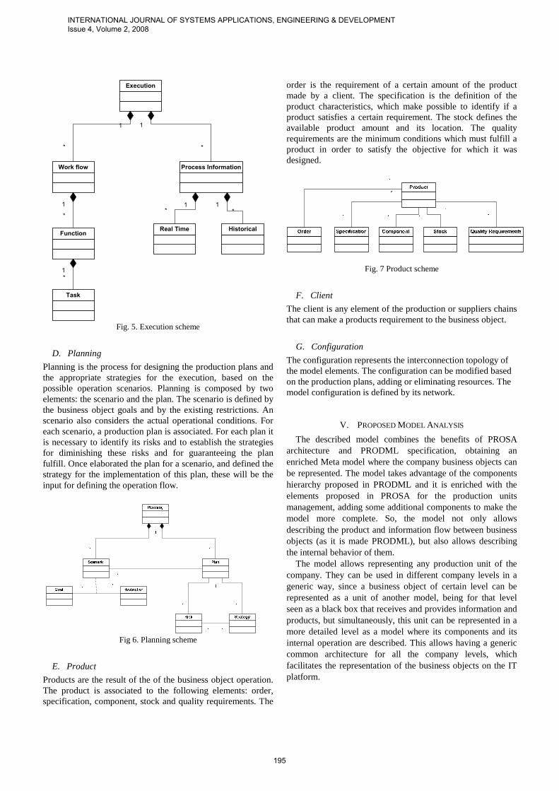
C. Execution
The execution contains the model dynamics. It is by means of the execution, that the business object can reach its goals and generate the products that are associated to him. The Execution has one fundamental component: the operation flow. The operation flow represents the activities that have to be completed in order to fulfill the business object objectives. The operation flow definition is obtained by means of programming in time the required functions to be executed to fulfill the industrial goals. The function represents a tasks combination made to fulfill the productive process objectives. Functions can be: control algorithms, recipes, work flows, rules or any other mechanism that allow using the resources in a coherent and structured way to fulfill the goals of the business object.
INTERNATIONAL JOURNAL OF SYSTEMS APPLICATIONS, ENGINEERING & DEVELOPMENT Issue 4, Volume 2, 2008
194
Execution
Work flow
1
*
FunctionReal Time Historical
Process Information
1*
1
*
1
*
1
*
1
*
Task
Fig. 5. Execution scheme
D. Planning
Planning is the process for designing the production plans and the appropriate strategies for the execution, based on the possible operation scenarios. Planning is composed by two elements: the scenario and the plan. The scenario is defined by the business object goals and by the existing restrictions. An scenario also considers the actual operational conditions. For each scenario, a production plan is associated. For each plan it is necessary to identify its risks and to establish the strategies for diminishing these risks and for guaranteeing the plan fulfill. Once elaborated the plan for a scenario, and defined the strategy for the implementation of this plan, these will be the input for defining the operation flow.
Fig 6. Planning scheme
E. Product
Products are the result of the of the business object operation. The product is associated to the following elements: order, specification, component, stock and quality requirements. The
order is the requirement of a certain amount of the product made by a client. The specification is the definition of the product characteristics, which make possible to identify if a product satisfies a certain requirement. The stock defines the available product amount and its location. The quality requirements are the minimum conditions which must fulfill a product in order to satisfy the objective for which it was designed.
Fig. 7 Product scheme
F. Client
The client is any element of the production or suppliers chains that can make a products requirement to the business object.
G. Configuration
The configuration represents the interconnection topology of the model elements. The configuration can be modified based on the production plans, adding or eliminating resources. The model configuration is defined by its network.
V. PROPOSED MODEL ANALYSIS
The described model combines the benefits of PROSA architecture and PRODML specification, obtaining an enriched Meta model where the company business objects can be represented. The model takes advantage of the components hierarchy proposed in PRODML and it is enriched with the elements proposed in PROSA for the production units management, adding some additional components to make the model more complete. So, the model not only allows describing the product and information flow between business objects (as it is made PRODML), but also allows describing the internal behavior of them.
The model allows representing any production unit of the company. They can be used in different company levels in a generic way, since a business object of certain level can be represented as a unit of another model, being for that level seen as a black box that receives and provides information and products, but simultaneously, this unit can be represented in a more detailed level as a model where its components and its internal operation are described. This allows having a generic common architecture for all the company levels, which facilitates the representation of the business objects on the IT platform.
INTERNATIONAL JOURNAL OF SYSTEMS APPLICATIONS, ENGINEERING & DEVELOPMENT Issue 4, Volume 2, 2008
195
VI. CASE OF STUDY: OIL PRODUCTION LOOP BY ARTIFICIAL
GAS LIFT
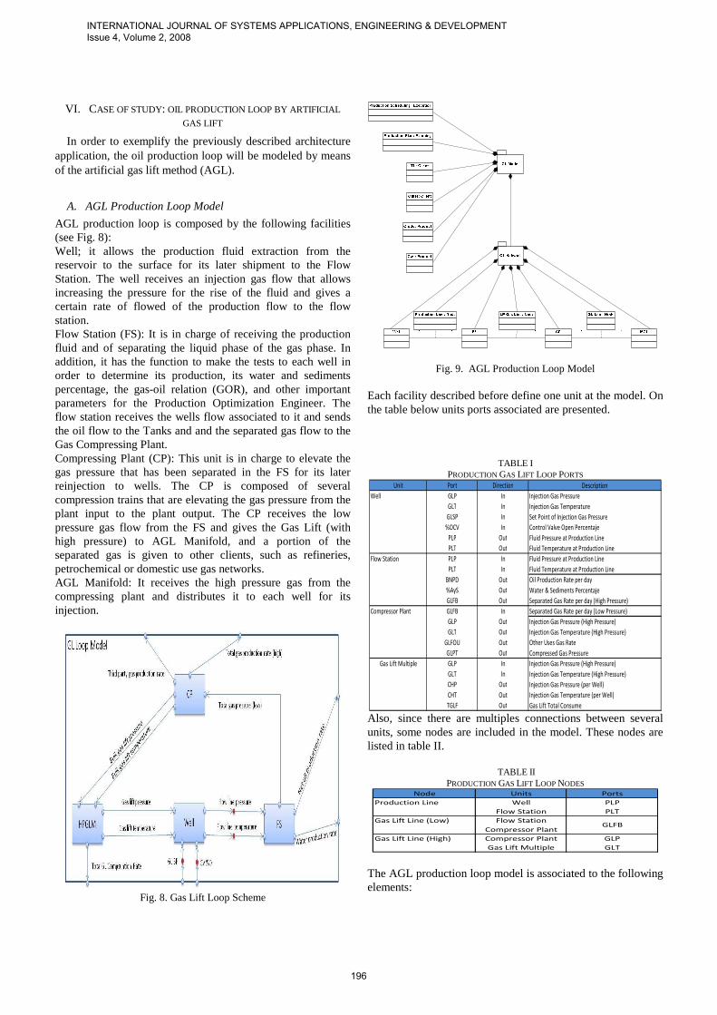
In order to exemplify the previously described architecture application, the oil production loop will be modeled by means of the artificial gas lift method (AGL).
A. AGL Production Loop Model
AGL production loop is composed by the following facilities (see Fig. 8): Well; it allows the production fluid extraction from the reservoir to the surface for its later shipment to the Flow Station. The well receives an injection gas flow that allows increasing the pressure for the rise of the fluid and gives a certain rate of flowed of the production flow to the flow station. Flow Station (FS): It is in charge of receiving the production fluid and of separating the liquid phase of the gas phase. In addition, it has the function to make the tests to each well in order to determine its production, its water and sediments percentage, the gas-oil relation (GOR), and other important parameters for the Production Optimization Engineer. The flow station receives the wells flow associated to it and sends the oil flow to the Tanks and and the separated gas flow to the Gas Compressing Plant. Compressing Plant (CP): This unit is in charge to elevate the gas pressure that has been separated in the FS for its later reinjection to wells. The CP is composed of several compression trains that are elevating the gas pressure from the plant input to the plant output. The CP receives the low pressure gas flow from the FS and gives the Gas Lift (with high pressure) to AGL Manifold, and a portion of the separated gas is given to other clients, such as refineries, petrochemical or domestic use gas networks. AGL Manifold: It receives the high pressure gas from the compressing plant and distributes it to each well for its injection.
Fig. 8. Gas Lift Loop Scheme
Fig. 9. AGL Production Loop Model Each facility described before define one unit at the model. On the table below units ports associated are presented.
TABLE I PRODUCTION GAS LIFT LOOP PORTS
Unit Port Direction Description
Well GLP In Injection Gas Pressure
GLT In Injection Gas Temperature
GLSP In Set Point of Injection Gas Pressure
%OCV In Control Valve Open Percentaje
PLP Out Fluid Pressure at Production Line
PLT Out Fluid Temperature at Production Line
Flow Station PLP In Fluid Pressure at Production Line
PLT In Fluid Temperature at Production Line
BNPD Out Oil Production Rate per day
%AyS Out Water & Sediments Percentaje
GLFB Out Separated Gas Rate per day (High Pressure)
Compressor Plant GLFB In Separated Gas Rate per day (Low Pressure)
GLP Out Injection Gas Pressure (High Pressure)
GLT Out Injection Gas Temperature (High Pressure)
GLFOU Out Other Uses Gas Rate
GLPT Out Compressed Gas Pressure
Gas Lift Multiple GLP In Injection Gas Pressure (High Pressure)
GLT In Injection Gas Temperature (High Pressure)
CHP Out Injection Gas Pressure (per Well)
CHT Out Injection Gas Temperature (per Well)
TGLF Out Gas Lift Total Consume Also, since there are multiples connections between several units, some nodes are included in the model. These nodes are listed in table II.
TABLE II PRODUCTION GAS LIFT LOOP NODES
Node Units Ports
Production Line Well PLP
Flow Station PLT
Gas Lift Line (Low) Flow Station
Compressor Plant
Gas Lift Line (High) Compressor Plant GLP
Gas Lift Multiple GLT
GLFB
The AGL production loop model is associated to the following elements:
INTERNATIONAL JOURNAL OF SYSTEMS APPLICATIONS, ENGINEERING & DEVELOPMENT Issue 4, Volume 2, 2008
196

Planning: defined by the production plan of the loop. it must consider each well production quota, the compressing plant gas pressure requirements, the total required production of the production loop, the CP compression capacity, the interconnection lines availability between the facilities (pipes), the wells intervention programming and the reservoir behavior. In the planning of the AGL operation loop, several scenarios can be presented, which will depend on the units and their resources availability, and on established production quotas for the loop. For each identified scenario a production plan must be elaborated that allows reaching the loop goals; in addition, the execution strategy must be defined considering the associated risks to each plan. Execution: it is defined by the loop production programming. Also, it includes the work flow for establish the production rates associated to each well, the CP shutdown and starting programming and the wells testing programs in the FS. In addition, the execution considers the injection and well production pressures and temperatures, the current moment (defined by SCADA systems), and the historical behavior (defined by historical Databases). Clients: for the case of AGL operation loops the clients are the Tanks (crude) and “other uses” clients (refineries, petrochemical, domestic networks) for the compressed gas. Products: the loop products are the crude and gas produced rates. The product stock is counted in the tanks and compressing plants output lines, and can be defined as the oil barrels per day (NBPD) or gas million cubical feet per day (MMCFD). The product specification is defined by dispatched crude API gravity or by the separated gas chromatography. The product quality is generally defined by the water cut for the crude and by the present hydrates amount in the gas. The product orders are defined by the crude and gas daily requirements that have been assigned to the loop. Resources: They are defined by the units and the model ports previously described. In addition, it includes the Personnel involved in the loop production management and the information platform associated to the operation which includes the surface network simulators, SCADA systems, historical management and Data Bases. In the following, to profit the recursivity of the model, a low level description of models units that belongs to the gas lift production loop -taking these units as models- will be given.
B. Well Model
A well is composed of the following units: Completion: Is the installation of coating and production pipes by which the hydrocarbons are transported from the reservoir to the surface. Also, it contemplates the necessary valves and pumps for the artificial lift method, as well as all the bottom variables sensors. Choke Valve: Is the valve that controls the injection gas flow to the completion. This valve controls the AGL method, since it controls the pressures system of the completion. Master Valve: Is the valve that controls the production fluid volume that leaves the completion.
Flow line Choke: is the valve that controls the production fluid volume towards the production line (pipe). The main function of this valve is to avoid that the fluid flows in opposite direction of the desired one (from the flow station to the well). Ports associated with the units above described are listed in the following board:
TABLE III
WELL PORTS Unit Port Direction Description
Completion CHP In Casing Head Pressure
CHT In Casing Head Temperature
QGI In Injection Gas Rate
THP Out Tubing Head Pressure
THT Out Tubing Head Temperature
Choke Valve GLP In Gas Lift Pressure
GLT In Gas Lift Temperaturee
CHP Out Casing Head Pressure
CHT Out Casing Head Temperature
QGI Out Injection Gas Rate
Master Valve THP In Tubing Head Pressure
THT In Tubing Head Temperature
PLDP Out Production Fluid Pressure Drop
Flow Line Choke PLDP In Production Fluid Pressure Drop
PLP Out Production Line Pressure
PLT Out Productiion Line Temperature The elements associated to the well model are: Planning: It is determined by the production rate associated to the well and its interventions programming (build up, draw down). The scenarios associated to the well are defined by the required production rate and the completion operation, including the reservoir behavior in the formation face (bottom of the hole). The plans will be associated to each scenario and generally they are related to the well optimal production, the well interventions programs (build up, draw down), chemistry injection for solving completion problems in the formation face, and the well programmed closing. Execution: It is defined by the gas injection control algorithm for the completion. For the execution it is necessary to have information concerning to the well injection and production pressures, as well as the gas injection line pressures. Client: Flow Station. Product: Production fluid. The product stock is measured in the flow station as the well obtained gross barrels amount per day. The product specification is defined by the desired water cuts, crude and gas, which are measured in the FS test separators. The quality parameters are defined by the gas-oil relation (GOR) and the production fluid water and sediments percentage generated by the well. The order is defined by the daily well stipulated production. Resources: They are determined by the described units and their ports. In addition, information systems are also consider as resources that register the variables associated to the well execution behavior, including SCADA systems and historical Data Bases; other considered resources are the well model, the configuration information and the interventions history that is also stored in the management data bases. In the following figure the well model in UML notation is presented.
INTERNATIONAL JOURNAL OF SYSTEMS APPLICATIONS, ENGINEERING & DEVELOPMENT Issue 4, Volume 2, 2008
197

Fig. 10. Well model
C. Flow Station Model
The flow station Model is made up of the following elements: • Entry Manifold: it receives the production of every well, and directs it to the well divider or to the proof divider-if the well is programmed for proofs. • Production Separator: this element is in charge of separate the liquid phase from the gaseous phase of the fluid. • Test Separator: it is the manager of measure the net production of every well, water and sediments percentage, gas production percentage and the relation gas - oil. • Depurator: It is responsible for processing the gas separated to eliminate hydrates and other not wished components and subsequently delivers it to the compressor plant. • Tank: it stores temporarily the liquid separated component. • Pump: In charge of raising the pressure of the production fluid in the line of dispatch to the farm tank. The ports associated with each of the described units previously are listed in the following table:
TABLE IV FLOW STATION PORTS
Unit Port Direction Description
Enter Manifold PLP In Production Line Pressure
PLT In Production Line Temperature
TPF Out Flow rate at the production separators exit
WTF Out Well Test Flow
Production Separator TPF In Total inflow Rate
PLF Out Outflow Rate
PGF Out Gas Outflow Rate
Test Separator WTF In Well Test Inflow Rate
WLF Out Separated Liquid Flow Rate (well test)
WGF Out Separated Gas Flow Rate (well test)
Depurator PGF In Inflow Gas Rate (well test)
WGF In Separated Gas Flow Rate (well test)
TGF Out Separated/Depurated Total Gas Flow (well test)
Tank PLF In Liquid Inflow Rate
WLF In Separated Liquid Inflow Rate (well test)
TLF Out Total Outflow Rate
Pump TLF In Total Liquid Inflow
TPF Out Total Liquid Outflow (high pressure) The nodes associated with each of the described units previously are listed in the following table:
TABLE V
FLOW STATION NODES Node Units Ports
In Enter Manifold PLP
Test Separator PLT
Production Separator PLF
Liquid Test Separator PLF
Production Separator WLF
Gas Test Separator PGF
Production Separator WGF The elements associated with the flow station model are the following: • Planning: determined by the production plan of the FS, which contemplates the goals of production per day and the well proof programming. The FS scenes are defined by the production rates of needed crude oil and the gas requirements of the compressor plants, besides the availability of the wells, of the lines of production and of the capacity of gas receipt in the compressor plants. In addition, the scenes must take into account the events happened in the wells associated with the FS, since they can alter the programming of well proofs to make. • Execution: determined by the algorithms of proof control of wells and dividers. At implementation real time and historical data of pressures, temperatures and levels in the dividers, must be provided, as well as pressures in the production lines, dispatch to farmtanks and compressor plants/station data and finally data of the resultant parameters of well proofs realized at proof dividers. • Client: farm tanks and gas compressor station. • Product: liquid Phase of the production fluid (crude oil more water) and separated gas. The stock of the product is measured at farmtanks and at compressor plants, also the quantity of crude oil barrels of per day (BPD) and million gas cubic feet per day (MMPCD) supplied by the FS. The specification of the product is determined by the gravity API of crude oil and by the chromatography of the supplied gas. The quality parameters are defined by the water cut in crude oil and by the quantity of hydrates presents in gas. The orders are defined by the rates of crude oil and gas production established for the FS and by the frequency of well proofs carried out. • Resources: resulting from described units and their ports. In Adittion, Data systems are also considered as resources which store the variable behavior of FS (SCADA systems historical DB), the databases of management and the model of network surface. • Configuration: determined by the network described before. The UML Flow station model is illustrated in the following figure.
INTERNATIONAL JOURNAL OF SYSTEMS APPLICATIONS, ENGINEERING & DEVELOPMENT Issue 4, Volume 2, 2008
198

*
1
*
Fig. 11. Flow Station Model
D. Compressor Plant Model
A compressor Plant is formed by the following elements: • Entry Module: it is in charge of receiving low pressure gas to distribute it to the modules of the plant compression modules. • Compression Train: it is responsible of raising the gas pressure across a turbine. Besides it contains a purifier that eliminates unwanted components in gas. • Exit Module: it gathers gas arriving from the compression modules and spreads it towards the high pressure gas network. Ports associated with described units previously are listed in the following table:
TABLE VI COMPRESSOR PLANT PORTS
Unit Port Direction Description
Enter Set TGF In Total Inflow Low Pressure Gas
GP Out Gas Pressure at each compression set exit
Compression Train GP In Gas Pressure at compression ser enter (low pressure)
CGP Out Compressed Gas Pressure (High Pressure)
CGT Out Compressed Gas Temperature (High Pressure)
Exit Set CGP In Compressed Gas Pressure (High Pressure)
CGT In Compressed Gas Temperature (High Pressure)
TPGP Out Third Party Exit Gas Pressure
TGP Out Compressed Gas Pressure (High Pressure)
GLP Out Injection Gas Pressure
TABLE VII COMPRESSOR PLANT NODES
Node Units Ports
Low Pressure Enter Set GP
Compression Train
High Pressure Compression Train CGP
Exit Set CGT The elements associated to the compressor plant model are: • Planning: determined by the compression plan and distribution of injection gas. The PC scenes extends over the
PC compression capacity, the availability of compression modules of high and low pressure networks and the delivery gas flow rate from EF. • Implementation: determined by the control algorithms of PC compression trains. For implementing the PC it is necessary the real time nd historical data of pressures, temperatures and volume of flow at the entry and exit of the plant, as well as in the entry and exit of every compression train. Also is essential to know speeds of turbines operation which compose the compression trains. • Client: Multiple AGL, other uses (petrochemicals, refineries, and domestic gas networks.). • Product: high pressure gas. The product stock is measured at the exit of the plant, just as the million gas cubic feet delivered per day. The specification is determined by the gas pressure and chromatography. The quality parameters are given by the minimal pressure needed from the exit of the plant and the quantity of hydrates that contains the gas. The orders are defined by the MLAG requirements and those others to whom gas is provided. • Resources: are determined by the described units and their ports. Systems of information that store the PC variables behavior (SCADA systems and historical BD), the BD of management and the network area model, are also considered as resources. • Configuration: determined by the network described before. The UML model illustration is showed next.
Fig. 12. Compressor Plant Model
E. Gas Lift Manifold Model
The units that compose a Multiple AGL (MAGL) are described below: • Entry cannon: it receives high pressure gas from gas compressor plant. • Distribution cannon: it distributes gas to every well associated to MAGL. • Merla Valve: it controls the outflow for injection to every well.
INTERNATIONAL JOURNAL OF SYSTEMS APPLICATIONS, ENGINEERING & DEVELOPMENT Issue 4, Volume 2, 2008
199

Ports associated to units before described are listed in the following table.
TABLE VIII GLM PORTS
Unit Port Direction Description
Enter Line TGLP In Total Gas Lift Pressure
DGLP Out Distribution Gas Lift Pressure
Distribution Line DGLP In Distribution Gas Lift Pressure
WGLP Out Well Gas Lift Pressure
WGLT Out Well Gas Lift Temperature
Merla Valve WGLP In Well Gas Lift Pressure
WGLT In Well Gas Lift Temperature
PSEUDOCHP Out Outflow Gas Lift Pressure per Well
TWCLF Out Total Gas Lift Pressure per day
PSEUDOCHT Out Outflow Gas Lift Temperature per Well The Nodes in the model of the MLAG are:
TABLE IX GAS LIFT MANIFOLD NODES
Node Units Ports
Enter Enter Cannon DGLP
Distribution Cannon
Cannon Distribution Cannon WGLP
Merla Valve WGLT • Planning: is determined by the gas distribution plan, which contemplates the total capacity of compression and the requirements of injection of every well. The scenes for the MAGL planning are defined by the requirements of injection of every well, the gas pressure delivered, the PC compression capacity and the availability of infrastructure (lines, valves, RTU). • Implementation: determined by control algorithms of the Merla valves of MAGL. For implementation is necessary to possess real time historically data of the pressures and volumen of fluid of MAGL entry and exit. • Client: Wells • Product: injection gas to the asked pressures. The product stock is measured as the million gas cubic feet per day completed by MAGL. The specification of the product is given by the dispatch pressure to every well. The quality parameters come given by the quantity of hydrates that contains the gas. The orders are determined by the rate of injection requested by every well. • Resources: determined by the described units and their ports. Moreover they data systems that there store MAGL variables (SCADA systems and historical DB), the databases of management and the model of the surface network, are also considered as resources. • Configuration: determined by the network described before. The UML illustration for MAGL model is described as follows:
Fig. 13. GLM Model
As we can see across the study case developed previously, the meta model proposed can be used to describe objects of business in different levels, supporting the same configuration.
VII. CONCLUSION
In this work is presented a data meta-model for representing business objects (their information and products flows) in production companies. The proposal is based on PRODML and PROSA models, in order to use industry and investigation community widely accepted standards. The proposed model uses the components hierarchy proposed in PRODML and is complemented with the holonic manufacture unit elements contemplated in PROSA, for introducing information components for the production management. Also, some additional components are added for completing the model. The presented model allows: • Representing the business objects by means of a common structure that simplifies the modeling task. • Representing diverse company levels in compositional and generic way. • Representing the product and information transference flows between the company facilities • The case of study presented allows exemplifying the model applicability in diverse levels of the company; in this particular case, Oil Production loop by Artificial Gas Lift. The definition of a data Meta-model is an important requirement for the systems and applications interoperability in production companies, allowing establishing a common ontology that ensures the information exchange and services execution.
REFERENCES
[1] ANSI/ISA 95.00.01. Enterprise Control System Integration. Part 1: Models and Terminology. January, 2003.
[2] B2MML. Business to Manufacturing Markup Language. Releases Notes. June, 2004. www.wbf.org.
INTERNATIONAL JOURNAL OF SYSTEMS APPLICATIONS, ENGINEERING & DEVELOPMENT Issue 4, Volume 2, 2008
200

[3] Babicenau, Radu y Frank Chen. Development and applications of holonic manufacturing systems: a survey. Journal of Intelligent Manufacturing, 17, 111–131, 2006.
[4] Bravo C., J, Aguilar, F. Rivas, M. Cerrada. "Design of an Architecture for Industrial Automation based on Multi-agents Systems", Proceeding of the 16th IFAC World Congress, 5 pages (CD), Prague, Checz Republic, July 2005.
[5] Chacón, Edgar, Besembel, Isabel & Jean Claude Hennet. Coordination and Optimization in Oil & Gas Production Complexes. ULA-LAAS. 2003.
[6] ISO. Industrial automation systems and integration -- Open systems application integration framework -- Part 1: Generic reference description. November 2003. www.iso.org.
[7] Marik, Vladimir & Pavel Vrba. Simulation in Agent Based Control Systems: a MAST Case Study. 16th IFAC World Congress. Praha. 2005.
[8] PABADIS. Plant Automation based on Distribuited Systems. Revolutionising Plant Automation – The PABADIS Approach. White Paper. (www.pabadis.org.). 2002.
[9] PRODML. Reference Architecture PRODML 1.0. www.prodml.org. Nov. 2006.
[10] Soma, R. Bakshi, A. Prassana, V. DaSsie W, and B. Bourgeois. Semantic Web Technologies for Smart Oil Field. Applications. SPE Intelligent Energy Conference & Exhibition. Amsterdam. February, 2008.
[11] WITSML. WITSML Data Schema Overview. POSC. 2006. www.witsml.org
[12] Wyns J. Architecture for Holonic Manufacturing Systems: The Key to Support Evolution and Reconguration. PhD thesis, K.U.Leuven, PMA Division. 1999
[13] F. Hidrobo, A. Ríos-Bolívar, J. Aguilar, L. León. An Architecture for Industrial Automation Based on Intelligent Agents. WSEAS Transaction on Computers, Issue 12, Volume 4, pp 1808-1815, December 2005.
[14] A. Ríos-Bolívar, F. Hidrobo, M. Cerrada, J. Aguilar. Control and Supervision System Development with Intelligent Agents. WSEAS Transactions on Systems, Issue 1, Vol. 6, pp 141-148, January 2007.
César Bravo, born in Maracaibo, Zulia State, Venezuela, the 9 of May 1977. He received the B. S. degree in System Engineering in 2000 (Universidad de Los Andes-Venezuela), the M.Sc. degree in Control and Automation Engineering in 2004 (Universidad de Los Andes-Venezuela), and now is candidate to the Ph. D degree in Applied Sciences (Universidad de Los Andes-Venezuela). He is Planning Manager of PDVSA Technological District at Mérida Venezuela, special division for research and development in Information Technology for the Oil & Gas Industry . He has published more than 10 papers in the field of artificial intelligence and enterprise integration architecture. M.Sc. Bravo has been a visiting research in the Laboratoire d’Analyse et d’Architecture des Systèmes at Toulouse, France. He has been the coordinator in several research or industrial projects, and has supervised 3 M. S. students in their thesis. Jose Aguilar received the B. S. degree in System Engineering in 1987 (Universidad de Los Andes-Venezuela), the M. Sc. degree in ComputerSciences in 1991 (Universite Paul Sabatier-France), and the Ph. D degree in Computer Sciences in 1995 (Universite Rene Descartes-France). He was a Postdoctoral Research Fellow in the Department of Computer Sciences at theUniversity of Houston (1999-2000). He is a Titular Professor in theDepartment of Computer Science at the Universidad de Los Andes. He has published more than 200 papers and 5 books, in the field of parallel anddistributed systems, computational intelligence, science and technology management, etc. Dr. Aguilar has been a visiting research/professor in different universities and laboratories, has been the coordinator or inviting research in more than 20 research or industrial projects, and has supervised more than 20 M. S. and Doctoral students in their thesis. Addison Ríos-Bolívar born in Upata, Bolivar State, Venezuela, the 30th of December 1961. He studied in the Liceo “Tavera Acosta” of his birth town, where he obtained his Bachillerato en Ciencias. From 1981 to 1987 he attended the School of Electrical Engineering of the University of Los Andes,(Venezuela) and he obtained the Electrical Engineer’s degree. From 1987 to 1991, he was working for Orinoco Steel Company in Matanzas,
Venezuela. In 1991, he was MSc. degree from the Los Andes University. In 1998, he was “Diplôme d'études à profondeur” (DEA) from the “Paul Sabatier” University (France). At 2001 he was “Docteur en Automatique” from the “Paul Sabatier” University (France). From 1991, his academic experience started as instructor professor at Los Andes University. Today, he is full professor in Control Systems Department, at Los Andes University. He has been invited professor in the Laboratoire d'Architecture et d'Analyse des Systèmes,(LAAS, Toulouse). He has also been technical assistant for “Petróleos de Venezuela” (PDVSA), “Venezolana de Aluminio” (VENALUM), “Siderúrgica del Orinoco” (SIDOR). In Los Andes University, he created the research group on Instrumentation and Control Applications, the research group on Estimation and Fault Diagnosis and the Intelligent Control Group. Prof. Ríos-Bolívar has over 100 publications in high level conferences and journals: the main topics of his papers are: Fault Detection and Isolation, Robust Control, Robust Estimation and Filtering, and Fault Tolerant Control. He has applied his results to many fields, among them: Chemical or Biochemical Processes Control and Supervision, Oil production, and Steel production processes. Also, has developed several tools for the teaching of the automatic control. Joseph Aguilar-Martin was Born in Barcelona (Catalonia, Spain) the 14th of May 1939. He studied in the Lycée Français of his birth town, where he obtained his Bacalauréat in Science with honors. From 1957 to 1962 he attended the ENSEEHIT (School of Electrical Engineering) of the University of Toulouse (France) and he obtained simultaneously the Electrotechnic Engineer’s degree and the “Licence ès Sciences Physiques”. In 1965 he was “Docteur Ingénieur” from the Toulouse University. Later, in 1968, he was delivered the title of member of Imperial College of Science and Technology in London (United Kingdom) and the London University MSc. Degree. His professional experience started as trainee in the Compagnie des Compteurs (Paris 1961), followed in 1963 by a short period as research assistant in Laboratoire de Génie Electrique in Toulouse (1965), where he cooperated in the design of high energy magnetic fields, until he joined Imperial College in London with a research scholarship until 1967. At this date he was appointed at the Centre National de la Recherche Scientifique (CNRS) in order to join the Laboratoire d’Automatique et des Applications Spatiales (LAAS), where he has been a member until the present days. There he created the research group on Stochastic Systems. In the meantime he has has been invited in several university research groups around the world; to mention the most relevant: Electronics Research Lab (ERL) at University of California Berkeley, (USA 1978), Universidade de Campinas “UNICAMP” (Brazil 1980, 1982, 1983), Universitat Politècnica de Catalunya “UPC” (Barcelona, Spain 1982, 1983, 1984, 2008), Ecole Polytechnique de Montreal (Canada, 1981), Universitat de Girona (Catalonia Spain 1997 , 1998), Universidad de los Andes “UNIANDES” (Bogotá Colombia 2000, 2001), Insituto Tecnológico de Monterrey (Atizapán Mexico, 2002), Universidad Autónoma Estado de Hidalgo ( Pachuca, Mexico 2004). Prof. Aguilar-Martin is presently “Professor Emeritus” in Toulouse and Catedrático of the Polytechnic University of Catalonia in Terrassa (Catalonia Spain). He has over 500 publications in high level conferences and journals: the main topics of his papers are: Stochastic systems, Estimation and Filtering, Fuzzy Logic Systems, Classification and Learning. He has applied his results to many fields, among them: Chemical or Biochemical Processes Control and Supervision, Hydrologic and Ecologic Systems modelisation, Aerospace Systems Diagnostic. Francklin Rivas-Echeverría was born in Mérida, Venezuela, the 30th of July 1969. He studied in the Colegio “Arzobispo Silva” of his birth town, where he obtained his Bachillerato en Ciencias. From 1987 to 1993 he attended the School of Systems Engineering of the University of Los Andes (Venezuela) and he obtained the Systems Engineer’s degree. From 1993 to 1994, he was working for the Venezuelan Aluminum Company in Matanzas, Venezuela. In 1996, he obtained the MSc. in Control Engineering from the Los Andes University. In 2000, he was “Doctor en Ciencias Aplicadas” from Los Andes University. From 1994, his academic experience started as instructor professor at Los Andes University. Today, he is full professor in Control Systems Department, at Los Andes University. He has been invited professor in the Laboratoire d'Architecture et d'Analyse des Systèmes,(LAAS, Toulouse), Universidad José Antonio Echeverría (La Habana, Cuba) and some Venezuela Universities. He has also been technical assistant for “Petróleos de
INTERNATIONAL JOURNAL OF SYSTEMS APPLICATIONS, ENGINEERING & DEVELOPMENT Issue 4, Volume 2, 2008
201

Venezuela” (PDVSA), “Venezolana de Aluminio” (VENALUM), “Siderúrgica del Orinoco” (SIDOR), Trolleybus System in Venezuela (TROLMERIDA). In Los Andes University, he created the Intelligent Systems Laboratory and is the head of the university consulting unit (UAPIT-ULA). Prof. Rivas-Echeverría has over 200 publications in high level conferences and journals: the main topics of his papers are: Artificial Intelligence, Intelligent Control, Automation Systems, Industrial Applications. He has applied his results to many fields, among them: Chemical or Biochemical Processes Control and Supervision, Oil production, and Steel production processes. Also, has developed several tools for the teaching of the automatic control. He is coauthor of two books concerning Artificial Intelligence and Nonlinear Systems.
INTERNATIONAL JOURNAL OF SYSTEMS APPLICATIONS, ENGINEERING & DEVELOPMENT Issue 4, Volume 2, 2008
202