a fully network controlled flight test center...
TRANSCRIPT

A Fully Network Controlled Flight TestCenter and Remote Telemetry Centers
Item Type text; Proceedings
Authors Rubio, Pedro; Jimenez, Francisco; Alvarez, Jesus
Publisher International Foundation for Telemetering
Journal International Telemetering Conference Proceedings
Rights Copyright © held by the author; distribution rights InternationalFoundation for Telemetering
Download date 22/05/2018 14:12:10
Link to Item http://hdl.handle.net/10150/579647

1
A FULLY NETWORK CONTROLLED FLIGHT TEST CENTER
AND REMOTE TELEMETRY CENTERS
Pedro Rubio, Francisco Jimenez, Jesus Alvarez
Airbus Military
Madrid, Spain
ABSTRACT
The purpose of this abstract is to show how Airbus Military Telemetry Ground Station has
evolved from a Single Ground Station towards a Distributed Ground Station. For this we had to
adapt ourselves to our growing number of remote stations, as well as developing the control
needed to reach full interoperability among remote stations. In short, creating a Virtual Ground
Station.
In this paper we describe the starting point, a single ground station and its control, and the arrival
point, different Ground Stations, and how control has evolved by using our own developed
software called ENCOS (Network Equipment COntrol System).
INTRODUCTION
Airbus Military’s first ever Flight Test Center had just one parabolic antenna for A/C tracking,
two Telemetry Receivers (master/spare) and two PCM Stream decommutators (master/spare). An
easy configuration.
Later on, as the number of instrumented prototypes grew, an additional antenna had to be put in
place along with another receiver and another decomm. More difficult but still manageable
without complex control.
During the following iterations, the complexity in number and type of equipment grew
exponentially. For example, adding different Receivers with different modulations, more
Parabolic antennas, Radios, Telemetry OverIP equipment, etc.
On top of that, new Remote Unattended Telemetry Centers were added like El Sabinar,
Montanchez and Moron in order to increase the Flight Test Airspace.
Wiring was becoming extremely complicated to manage. Remote Centers connectivity and
configuration needed to be orchestrated and synchronized

2
The aim of this paper is to explain the modifications that we have had to implement to reach our
goal, develop a Virtual Flight Test Center allowing telemetry supported Flight Tests all along the
covered zone with an easy, quick and fail proof configuration process.
FIRST STAGE: ONE FLIGHT TEST CENTER, ONE ANTENNA
The architecture shown on Figure 1: One Flight Test Center. One Antenna represents a very
simple Flight Test Center.
Note that only Telemetry related equipment is shown although radio communication equipment
was also present.
The elements involved are:
1 Parabolic Antenna
1 RF Patch Panel
2 Telemetry Receivers
1 PCM Patch Panel
1 PCM Decommutator
1 Video Decompressor
1 Audio Decompressor
At this stage there was no software control. Configuration of both equipment settings and signal
routing was made manually using mechanical means and human operator.
Figure 1: One Flight Test Center. One Antenna

3
SECOND STAGE: ONE FLIGHT TEST CENTER, TWO ANTENNAS
At this stage the configuration complexity increased, two telemetry chains had to be working
together and additional equipment was incorporated.
As shown in Figure 2: One Flight Test Center. Two Antennas the main changes from Stage 1
were the increased number of equipment and therefore the higher capacity of the patch panels.
Figure 2: One Flight Test Center. Two Antennas
4
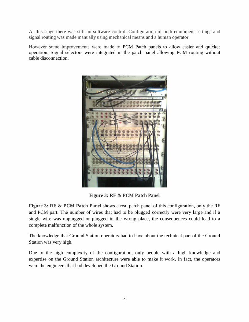
At this stage there was still no software control. Configuration of both equipment settings and
signal routing was made manually using mechanical means and a human operator.
However some improvements were made to PCM Patch panels to allow easier and quicker
operation. Signal selectors were integrated in the patch panel allowing PCM routing without
cable disconnection.
Figure 3: RF & PCM Patch Panel
Figure 3: RF & PCM Patch Panel shows a real patch panel of this configuration, only the RF
and PCM part. The number of wires that had to be plugged correctly were very large and if a
single wire was unplugged or plugged in the wrong place, the consequences could lead to a
complete malfunction of the whole system.
The knowledge that Ground Station operators had to have about the technical part of the Ground
Station was very high.
Due to the high complexity of the configuration, only people with a high knowledge and
expertise on the Ground Station architecture were able to make it work. In fact, the operators
were the engineers that had developed the Ground Station.

5
THIRD STAGE: ONE FLIGHT TEST CENTER AND A REMOTE TELEMETRY
CENTER
As Flight Test Prototypes increase along with the flight test requirements (more range, low
altitude tests…), a remote telemetry center become a must.
Figure 4: 10,000ft One antenna coverage
Figure 5: 10,000ft Two antenna coverage
Figure 4: 10,000ft One antenna coverage shows the antenna coverage for 10,000 ft, and the
need to cover a new test area at this altitude. In Figure 5: 10,000ft Two antenna coverage is
shown the coverage of both antennas, fitting the new requirement for the new test area.
The addition of a remote unattended telemetry center is shown in Figure 6: A Flight Test
Center with two antennas and a Remote Telemetry Center.
A remote unattended telemetry center should have:
1 TM antenna
1 Telemetry Receiver
1 PCM to IP Converter
U/VHF capabilities
Complete remote control

6
Figure 6: A Flight Test Center with two antennas and a Remote Telemetry Center
The infrastructure of this Ground Station is of the most complicated type that can still be
managed with only external wires, patch panels, manual signal selectors…
Any addition to Flight Test Center Infrastructure would lead it to become impossible to handle in
that way. As a consequence, another solution had to be implemented.
On the other hand the intention was to be able to control the Ground Station and Remote
Telemetry Centers without needing a high knowledge of the systems. This would allow less
skilled operators to do the job while freeing up engineers to develop new technologies.
FOURTH STAGE: TWO FLIGHT TEST CENTER AND A SEVERAL REMOTE
TELEMETRY CENTERS
At this stage we had to manage:
Two Flight Test Centers, with the following characteristics per center
o Two telemetry antennas
o Two monitoring rooms
7
o Three U/VHF systems
o Network controlled
Three Remote Telemetry Centers, with the following characteristics per center
o One telemetry antenna
o No monitoring
o One U/VHF system
o Network controlled
To face these new requirements we had to develop a brand new control system that allows
operators to control and monitor every piece of equipment on the Ground Station. We called this
concept Smart GS Control System.
This new control system should be:
IP Network based
o IP Networks are present worldwide
o Location agnostic
o Cheap, easy to deploy and grow
Distributed
o GS should be controllable from any company/organization site
Concurrency proof
o Control System shall prevent equipment blocked by monopolizing user
o Control System shall allow several users to monitor/control equipment
concurrently
Scalable Architecture
o Control System should be able to accommodate growth without deep changes
Intuitive & Automated User Interface
o As equipment quantity and complexity grows, it is really important to have an
intuitive user interface
o Setting and configuring some equipment can be complex, time consuming and
error prone. Therefore automated processes are a plus
o Simple User actions are translated transparently to several more complex
equipment commands.
Heterogeneous Equipment Support
o Control System should allow control of any kind of equipment (no matter the
interface type)
o Use of plug-ins for every equipment type
Isolation o Control System should isolate the specific syntax/protocol of every device from
the common Client-Server protocol
All this characteristics were implemented in a Client-Server Architecture, where
Client, any PC/Tablet with the client SW installed
o As many clients as needed
Server, any PC with the Server SW installed
o Few servers. Usually one or two per site

8
o A given device can only be connected/controlled by one server
o Server acts as a CMDs/RESPs router to devices
Hardware architecture is based on:
COTS (Commercial Off The Shelf)
o PC Based
Client and server
o Network IP equipment
o Different types of interfaces
RS232
RS422
GPIB
…
Figure 7: Hardware architecture
Figure 7: Hardware architecture shows the basic hardware architecture to control several
devices involved in the Ground Station.
Figure 8: Software architecture
Figure 8: Software architecture shows the basic principles of the Smart GS Control System.

9
The key points from the software point of view are:
Use of UDP instead of TCP.
o Avoid complex connection pool management
o Reliable. Inside WAN/LAN
Use of multicast
o Avoid complex clients tables management. Switches do the work better than us!
o Saves bandwidth
Data sent on the UDP Payload are Generic Classes serialized in XML
Messages
o Periodic
Server sends periodic status updates of every connected device
o On demand
CMD/RESP messages are exchanged when clients want the server to
execute an action
We call all this stuff ENCOS (Equipment Network COntrol System).
ENCOS is the Airbus Military customized implementation of a Smart GS Control System.
Control involves two main actions:
Routing of signals (Video, Audio, PCM, RF) …
o For that purpose we use RF matrix, PCM matrix, Video matrix, Audio matrix…
Changing devices settings
o Every device can be configured, including receivers, ACUs, demux…
ENCOS has two main benefits:
It allows to control GS devices in an efficient and easy manner
It allows to automate and simplify complex tasks into simple user actions
The use of ENCOS is just a matter of drag & drop a device into another to make a link. Only
compatible devices can be linked. Several rules have been implemented to ease the use of this
software to a newcomer.

10
Figure 9: ENCOS Software
Actual ENCOS software to control Getafe Ground Station can be seen in Figure 9: ENCOS
Software.
CONCLUSION
As complexity grows, errors and time to configure a Flight Test Center increase as well. There is
no option but to relay on a Smart GS Control System.
If the main advantages had to be summarized, they would be:
Error mitigation by offering very limited and simple actions to operators
Time to perform configuration changes greatly reduced because of the simplicity of User
actions
As a consequence, in addition to be a very important advantage, the learning period of a new
operator has been reduced drastically; nowadays we can make a newcomer Ground Station
operator fully operative in a couple of weeks.