a four quadrant dc motor closed-loop speed control based on a … · 2019-07-13 · control...
TRANSCRIPT

Vol. 10(35), Jan. 2020, PP. 4471-4482
4471
Article History: Received Date: Apr. 14, 2019 Accepted Date: Jun. 06, 2019 Available Online: Jan. 01, 2020
A Four Quadrant DC motor Closed-Loop Speed Control Based on a
Patterned-Disk Optical F/V Feedback Sensor system
Ignatius I. Uzoeto1.* and Emenike C. Ejiogu2 1, 2 Department of Electrical Engineering University of Nigeria Nsukka, Nsukka, Nigeria
Phone Number: +234-08039401810
*Corresponding Author's E-mail: [email protected]
Abstract
his paper is aimed at designing and implementing an optical feedback control system for a PWM
four quadrant chopper driven conventional DC motor. Motor speed control is achieved from an
efficient feedback measuring accuracy. In the implementation of the feedback path, an optical
sensor and a patterned disk are the transducer for converting the output speed of the motor to voltage.
The results obtained shows the interaction of the speed and voltage, and the PWM signal generated for
the four quadrant chopper switches. And the feedback system provides an effective response to any
change in the system’s output and the practicable advantage of the high efficiency brands it an optimal
control.
Keywords: DC Motor, Patterned-disk, Optical Sensor, feedback path, four quadrant chopper, F/V
1. Introduction
As technology advances in the aspect of system operations, so also is improvement in the use of
control laws and mechatronics configuration in system design and control. Practical system dynamics
are subject to non-linearity which could be due to sudden internal and or external change of condition
and disturbances [1]. Automatic control operation is to ensure that certain system parameters; such as
system temperature, pressure, voltage and speed (as in our case) follow the preset control laws applied
in the design and to bring these parameters to certain pre-defined values (set-points) and to maintain
them against any possible disturbing influence [1], [2], [3]. Different control technique can be adopted
for a close loop control system it can be modern or classical control technique and in any case requires
a form of sensor and feedback path. The accuracy and efficiency of the control action of the entire
system rest on the feedback path and the implicit functions of its individual subsystem. Different control
techniques and research works are been developed and used in the control of a conventional DC motor
based on the configuration of its fields and armature windings as to separately-excited DC motor. Some
of these techniques includes those of [4], [5], [6], [7], [8] and numerous others who presented and
proposed a speed controller for DC motor by a way of comparing classical control “PI” and modern
control “Sliding Mode control” strategies and drawing conclusion on the optimal control strategy. Also
considering the works of [9], [10] and others who carried out analysis on estimating the speed of a DC
motor and presented the possibility of controlling a DC motor speed explicitly sensor-less. In both cases:
with sensor and sensor-less the output variable is measured or estimated so the efficiency and critical
analysis of the measuring unit or sensor control still remain important.
1.1 DC Motor Model
DC motor speed control and it transient response in industrial applications has made it relevant
despite its size to power ratio and the dominance of the induction motor. And it control system
development is an interesting area to explore [6]. The system used in this paper is a fixed voltage field
T

Ignatius I. Uzoeto et al. / Vol. 10(35), Jan. 2020, PP. 4471-4482
4472
International Journal of Mechatronics, Electrical and Computer Technology (IJMEC)
Universal Scientific Organization, www.aeuso.org PISSN: 2411-6173, EISSN: 2305-0543
that is armature controlled and operated in the constant flux region. Figure (1) describes both the
electrical and mechanical variables, by applying the subsequent circuit and motion laws we develop
Equations (1), (2) and (3).
Figure 1: DC Motor Equivalent circuit
𝑣𝑎(𝑡) = 𝑅𝑎 ∗ 𝑖𝑎(𝑡) + 𝐿𝑎 ∗𝑑𝑖𝑎
𝑑𝑡+ 𝑒𝑏(𝑡) (1)
𝑒𝑏(𝑡) =𝑃∗𝜙∗𝑍
2𝜋∗ 𝜔𝑚(𝑡) = 𝑘𝑏 ∗ 𝜔𝑚(𝑡) (2)
𝑇𝑚(𝑡) = 𝑘𝑏 ∗ 𝑖𝑎(𝑡) = 𝐽𝑚 ∗𝑑𝜔𝑚
𝑑𝑡+ 𝑏𝑚 ∗ 𝜔𝑚(𝑡) (3)
Where;
𝑣𝑎 and 𝑖𝑎 = Armature voltage and Current
𝑅𝑎and 𝐿𝑎 =Armature Resistance and Inductance
While
𝑣𝑓 , 𝑖𝑓 , 𝑅𝑓 and 𝐿𝑓 = Are the field equivalent
𝑒𝑏 , 𝑇𝑚 and 𝜔𝑚 = The back EMF, motor torque and speed respectively
𝐽𝑚 and 𝑏𝑚 = Inertia and damping coefficient
Applying the Laplace transform we get the transfer function of the above equation that relates the motor
speed to the armature voltage considering load torque 𝑇𝐿 as zero and as input;
𝐺Ω(𝑠) =Ω(𝑠)
𝑉(𝑠)|
𝑇𝑙(𝑠)=0=
𝐾𝑚
(𝐿𝑎𝑠+𝑅𝑎)(𝐽𝑚𝑠+𝐵𝑚)+𝐾𝑚2 (4)
𝐺L(𝑠) =Ω(𝑠)
𝑇𝐿|
𝑉(𝑠)=0= −
𝐿𝑎𝑠+𝑅𝑎
(𝐿𝑎𝑠+𝑅𝑎)(𝐽𝑚𝑠+𝐵𝑚)+𝐾𝑚2 (5)
And the state space representation is
= 𝐴𝑥 + 𝐵𝑢 = [−
𝑏𝑚
𝐽𝑚
𝐾𝑚
𝐽𝑚
−𝐾𝑚
𝐿𝑎−
𝑅𝑎
𝐿𝑎
] 𝑥 + [−
1
𝐽𝑚0
01
𝐿𝑎
] 𝑢 (6)
+
−
𝑉𝑓
𝑇𝑚, 𝜔𝑚
𝑏𝑚 𝐽𝑚 𝐸𝑏
𝐿𝑎
𝐿𝑓
𝑅𝑓 𝑖𝑓
𝑅𝑎 𝑖𝑎
𝑉𝑎
+
−

Ignatius I. Uzoeto et al. / Vol. 10(35), Jan. 2020, PP. 4471-4482
4473
International Journal of Mechatronics, Electrical and Computer Technology (IJMEC)
Universal Scientific Organization, www.aeuso.org PISSN: 2411-6173, EISSN: 2305-0543
𝑥 Is a two dimensional vector 𝑥 = [𝑥1 𝑥2]𝑇 where 𝑥1 and 𝑥2 are angular velocity of the shaft and
armature current respectively represents differentials of 𝑥. 𝑢 = [𝑇𝐿 𝑉𝑎]𝑇
1.2 Closed-loop path
An optical interrupter sensor senses the speed of the DC motor, thereby generating a pulse train
of high and zero amplitude when light is blanked and allowed to pass through the patterned disc. This
light and dark interval of the slot sensor gives a pulse signal with a frequency proportional to motor
speed, the frequency of this waveform is given by [11]
𝑓𝑚 =𝑁∗𝑟𝑝𝑚
60 (7)
Where;
𝑓𝑚 = Frequency of the output waveform
𝑟𝑝𝑚 = Speed in revolution per minute
𝑁 = Number of white or black strips on the disc
The frequency is then converted to a voltage signal and sent to a comparator with control set-point to
produce an error signal for the system compensator.
1.3 Dc drive
With the advent of DC-DC chopper variable speed of DC motors became a reality. Choppers are
static switch used to convert fixed DC to variable DC [12]. There are five types of this DC choppers
[12]. The proposed project implementation is done with the four quadrant chopper type. The chopper
utilizes the full bridge H switch topology. The four quadrant operation enables us to drive the DC motor
in all four quadrant of motor drive of forward, reverse, forward-braking and reverse-braking operation.
Figure 2 gives a description of the chopper.
Figure 2: Full bridge four quadrant chopper
2 Design outline and procedure
The design was implemented in as different modules to simplify circuit design, building and
assembling as shown in Figure 3.
−
𝑇1
𝑇3 𝑇4
𝑇2 𝐷2
𝐷4 𝐷3
𝐷1
+ 𝑉𝑎 C + −
𝑉𝑜
𝑖𝑎
𝑖𝑜
𝐸𝑏 + −

Ignatius I. Uzoeto et al. / Vol. 10(35), Jan. 2020, PP. 4471-4482
4474
International Journal of Mechatronics, Electrical and Computer Technology (IJMEC)
Universal Scientific Organization, www.aeuso.org PISSN: 2411-6173, EISSN: 2305-0543
Figure 3: Proposed system Block Diagram
The source voltage to the system is certainly of the DC nature, of which can be sourced directly from
a DC source or from a rectified and filtered AC source of which the latter is in our case.
The feedback path consist of an Opto-interrupter which is a non-contact sensor for detecting the
rotational speed/frequency of the motor, a patterned disk for interrupting the light wave of the sensor, a
signal conditioner which converts this train of pulses. The sensor consist of an optical emitter of an
infrared LED, and an optical detector which is an infrared phototransistor.
In the design of the four quadrant chopper the pulse width modulation (PWM) technique is employed
for the periodic switching of the chopper switch pair (𝑇1, 𝑇4) and (𝑇2, 𝑇3). This logic control consist of a
triangular wave circuit a comparator and a dc reference signal input from the feedback controller (be it
PI or Sliding Mode Control).
3 Design implementation
The design implementation is according to that of Figure 4, this paper focuses on the feedback path
and as that the circuits of the PWM and controller (PI and SMC) and the control analysis on equations
(4), (5) and (6) is not elaborated here in this paper.
Figure 4: Circuit Module diagram of the closed-loop system
The output of the opto-interrupter is a binary high or low based on whether light from the emitter is
received by the detector.
𝑉𝑟𝑒𝑓
𝑉𝑠
DC-DC Converter
Signal
Conditioner
𝑉𝑚
Feedback and PWM
controller
Optical sensor
𝑓𝑚 𝑓𝑠
PWM Signal Frequency proportional
to shaft speed Voltage corresponding
speed
Equally spaced Disk
𝜔𝑚
DC Motor
Controller circuit. Comparator
−
𝑇1
𝑇3 𝑇4
𝑇2 𝐷2
𝐷4 𝐷3
𝐷1 +
𝑉𝑎 𝑉0 M 𝐿𝑜𝑎𝑑
Opto-interrupter
circuit F-V converter
𝜔∗ 𝜔
PWM control logic circuitry.
𝑇1 𝑇2 𝑇3 𝑇4
𝑉𝑓
𝐿𝑓𝑖𝑙𝑡𝑒𝑟
+
−
𝑖𝑎
𝑖𝑓
Ignatius I. Uzoeto et al. / Vol. 10(35), Jan. 2020, PP. 4471-4482
4475
International Journal of Mechatronics, Electrical and Computer Technology (IJMEC)
Universal Scientific Organization, www.aeuso.org PISSN: 2411-6173, EISSN: 2305-0543
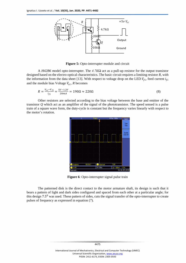
Figure 5: Opto-interrupter module and circuit
A H42B6 model opto-interrupter. The 4.7KΩ act as a pull-up resistor for the output transistor
designed based on the electro-optical characteristics. The basic circuit requires a limiting resistor R, with
the information from the data sheet [13]. With respect to voltage drop on the LED 𝑉𝑓𝑖, feed current 𝑖𝑓𝑖
and the module bias Voltage 𝑉𝑐𝑐, R becomes
𝑅 =𝑉𝑐𝑐−𝑉𝑓𝑖
𝑖𝑓𝑖=
5𝑉−1.2𝑉
20𝑚𝐴= 190Ω ≈ 220Ω (8)
Other resistors are selected according to the bias voltage between the base and emitter of the
transistor Q which act as an amplifier of the signal of the phototransistor. The speed sensed is a pulse
train of a square wave form, the duty-cycle is constant but the frequency varies linearly with respect to
the motor’s rotation.
Figure 6: Opto-interrupter signal pulse train
The patterned disk is the direct contact to the motor armature shaft, its design is such that it
bears a pattern of light and dark sides configured and spaced from each other at a particular angle; for
this design 7.50 was used. These pattern of sides, cuts the signal transfer of the opto-interrupter to create
pulses of frequency as expressed in equation (7).
+5𝑣 𝑉𝑐𝑐
Output
Ground
𝑅
4.7𝑘Ω
200Ω
10𝑘Ω
𝑄

Ignatius I. Uzoeto et al. / Vol. 10(35), Jan. 2020, PP. 4471-4482
4476
International Journal of Mechatronics, Electrical and Computer Technology (IJMEC)
Universal Scientific Organization, www.aeuso.org PISSN: 2411-6173, EISSN: 2305-0543
Figure 7: Patterned Disk
A frequency to voltage (F/V) converter come in as a signal conditioner which convert’s the
frequency to voltage that is then sent to the controller. An LM331 IC is used to achieve this goal. Supply
voltage, ground, timing resistor and current set resistors are all connected as in Figure 8
Figure 8: F/V Converter circuit [14]
As expressed in [14], we can relate the functions of the individual components
For our construction the maximum frequency of operation as measured with the help of the patterned
disk which makes a total of 24 ON pulse and 24 OFF pulse, we get using equation 7.
𝑓𝑚 =24 𝑝𝑢𝑙𝑠𝑒
𝑟𝑒𝑣×
3000 𝑟𝑒𝑣
𝑚𝑖𝑛×
1 𝑚𝑖𝑛
60 𝑠 = 1200𝐻𝑧
The output of the converter can be manipulated from equation (9)
𝑉𝑂𝑢𝑡 = 𝐹𝐼𝑁 × (𝑅𝐿
𝑅𝑠⁄ ) × (1.9𝑣) × (1.1𝑅𝑡𝐶𝑡) (9)
𝑅𝐿 Is the filter/load resistor and 𝑅𝑠 is the current-set resistor. Component selection as 𝑅𝐿 = 100𝑘Ω
and 𝑅𝑠 = 12𝑘Ω with a 5𝑘Ω potentiometer. 𝑅𝑡 Is the timing resistor while 𝐶𝑡 the timing capacitor
picked as 68𝑘Ω and 0.01𝜇𝐹 respectively for a 10𝑉 full-scale output.
The rotating disk, opto-sensor and the F-V converter make up the transducer circuitry. The
dynamic performance specification as regards the accuracy, repeatability, linearity, resolution as well
as the response rate of the transducer is compiled as related to each components in the circuitry. The
opto-interrupter’s rise and fall time is 15 μseconds, which determines how fast it responds it’s a change
in its input. For our module apply equation (10)
𝑓 =1
𝑇=
1
15×10−6 = 66.66𝐾𝐻𝑧 (10)
From equation 11 it can be seen that the frequency range of the module convers the maximum
speed capability of the patterned disk. The patterned disk is divided as much as possible so as to ensure
better accuracy transmitted to the opto-interrupter and also to reduce sluggish response of the module.
1uF
+12𝑉𝑐𝑐
10kΩ
18kΩ 100kΩ
0.01uF
68kΩ
LM331
8 7 5
6
3
1
4 2
470pF
68kΩ 10kΩ
Frequency
signal Voltage
output

Ignatius I. Uzoeto et al. / Vol. 10(35), Jan. 2020, PP. 4471-4482
4477
International Journal of Mechatronics, Electrical and Computer Technology (IJMEC)
Universal Scientific Organization, www.aeuso.org PISSN: 2411-6173, EISSN: 2305-0543
Just as the module handles response, the disk handles the resolution of the transducer while the F-V
converter handles the repeatability, accuracy and linearity of the sensor
Figure 9: Signal output as seen in pin 6
4 Hardware and result 4.1 Setup
A laboratory prototype test bench was developed and built as shown in Figure 10 with a 250W 63-111 model Feedback DC machine. The operation of the control method has been found to be 95% stable.
It is designed with four IRFP460 MOSFETS mounted on heat sinks with each switch having a 0.1μF 600V capacitor and 5W, 5.6Ω resistor connect as a snubber to protect the switches. The AC voltage through a Variac is rectified and filtered using a 10A full bridge rectifier and two 470μF/450V capacitors. And the switching pulses are generated from analog ICs using TL084 op-amp IC to generate the triangular wave whose frequency we fixed at 3𝐾𝐻𝑧 and compared with a DC value from the controller and thus
Spiked Signal
Figure 10: Experimental setup
PSU
Patterned Disk Feedback Path
Logic circuit
Rectifier and Filter
Oscilloscope
DC motor
H-Bridge
Varactor
Ignatius I. Uzoeto et al. / Vol. 10(35), Jan. 2020, PP. 4471-4482
4478
International Journal of Mechatronics, Electrical and Computer Technology (IJMEC)
Universal Scientific Organization, www.aeuso.org PISSN: 2411-6173, EISSN: 2305-0543
produce the triggering pulses passed through a dead-band circuit and switch drivers. The system was tested and measured with a Tektronix TBS1052B digital Oscilloscope.
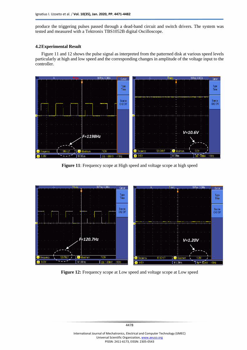
4.2 Experimental Result
Figure 11 and 12 shows the pulse signal as interpreted from the patterned disk at various speed levels particularly at high and low speed and the corresponding changes in amplitude of the voltage input to the controller.
Figure 11: Frequency scope at High speed and voltage scope at high speed
Figure 12: Frequency scope at Low speed and voltage scope at Low speed
V=10.6V F=1198Hz
F=120.7Hz V=1.20V

Ignatius I. Uzoeto et al. / Vol. 10(35), Jan. 2020, PP. 4471-4482
4479
International Journal of Mechatronics, Electrical and Computer Technology (IJMEC)
Universal Scientific Organization, www.aeuso.org PISSN: 2411-6173, EISSN: 2305-0543
Figure 13 – 15 shows the Triangular wave, the DC reference signal, the PWM waveform and the firing
signal across the bridge.
Figure 13: DC signal and Triangular wave signal
Figure 14: Pulse Width Modulated Signal
Figure 15: Gating Signals for switches T1 and T3
𝑇1
𝑇3
Triangular wave DC Reference signal

Ignatius I. Uzoeto et al. / Vol. 10(35), Jan. 2020, PP. 4471-4482
4480
International Journal of Mechatronics, Electrical and Computer Technology (IJMEC)
Universal Scientific Organization, www.aeuso.org PISSN: 2411-6173, EISSN: 2305-0543
Figure 16: Firing Signal across the H-Bridge
Table 1 is used to show the test for accuracy of the F/V converter.
Table 1: F/V converter test of Accuracy
Frequency (Hz) True Output
Calculated
(V)
Actual Voltage
Measured
(V)
Error (V) % FSO
0 0 0.008 -0.008 -0.067
120.8 1.21 1.2 0.01 0.0833
279.3 2.79 2.8 -0.01 -0.083
483 4.83 5.0 -0.17 -1.42
606.8 6.07 6.4 -0.33 -3.75
735 7.35 7.8 -0.45 -2.75
935 9.35 9.4 -0.05 -0.42
1197 11.97 10.6 1.37 11.42
Figure 17: Graph output voltage against input frequency

Ignatius I. Uzoeto et al. / Vol. 10(35), Jan. 2020, PP. 4471-4482
4481
International Journal of Mechatronics, Electrical and Computer Technology (IJMEC)
Universal Scientific Organization, www.aeuso.org PISSN: 2411-6173, EISSN: 2305-0543
Equation 11 [14] is used to form the last column of table 1 𝑉𝑓𝑢𝑙𝑙 𝑠𝑐𝑎𝑙𝑒 = 12𝑣 and 𝐼𝑛𝑝𝑢𝑡𝑓𝑢𝑙𝑙𝑠𝑐𝑎𝑙𝑒 =
1.2𝑘𝐻𝑧. The accuracy is gotten as a percentage of full scale output (FSO) and the largest deviation
recorded is 11.42% which place the efficiency of the converter at about 90%
𝑉𝑡𝑟𝑢𝑒 =𝑉𝑓𝑢𝑙𝑙 𝑠𝑐𝑎𝑙𝑒
𝑖𝑛𝑝𝑢𝑡𝑓𝑢𝑙𝑙𝑠𝑐𝑎𝑙𝑒× 𝑖𝑛𝑝𝑢𝑡 (11)
The transducers efficiency with little approximation could thus be calculated as.
𝜂𝑇𝑟𝑎𝑛𝑠𝑑𝑢𝑐𝑒𝑟 = 𝜂𝑑𝑖𝑠𝑘 × 𝜂𝑜𝑝𝑡𝑜 × 𝜂𝑓−𝑣 (12)
𝜂𝑇𝑟𝑎𝑛𝑠𝑑𝑢𝑐𝑒𝑟 = 0.98 × 0.98 × 0.90
𝜂𝑇𝑟𝑎𝑛𝑠𝑑𝑢𝑐𝑒𝑟 = 0.864 ≈ 86%
The gain 𝐾𝑠𝑔 of the feedback path can be represented as the accuracy of the transducer as shown in
Figure 18
Figure 18: Feedback gain of the Close-loop system
Conclusion
In this work, an approach is used to develop a closed-loop system control for a DC motor to obtain
optimum feedback path control. The suggested method basically uses a patterned-disk optical F/V
feedback sensor system which helps effectively to close the system loop. With the results obtained the
accurate record of the speed is converted with little or no loss in the entire feedback system
configuration.
Reference
[1] M. Schlelcher and F. Blasinger, Control Engineering : A guide for Beginners, Fulda Germany: Jumo GmbH and Co.
KG, 2003.
[2] F. Golnaraghi and B. C. Kuo, Automatic Control Systems 9th Edition, New Jersey USA: John Wiley and Sons, Inc.,
2010.
[3] R. S. Burns, Advanced Control Engineering, Jordan Hill, Oxford: Butterworth-Heinemann, 2001.
[4] N. H. Hyng and V. A. Utkin, "Mathematical Aspects of Power Plant Control : CONTROL OF DC ELECTRIC
MOTOR," Automation and Remote Control, vol. 67, no. 5, pp. 767 - 782, 2006.
[5] T. D. Kumar and S. J. Mija, "Design and Performance Evaluation of Robust SMC schemes for speed control of DC
motor," in IEEE International Conference on Advanced Communication Control and Computing Technologies
(ICACCCT), 2014.
[6] S. V. Ambesange, S. Y. Kamble and D. S. More, "Application of Sliding Mode Control for Speed Control of DC
Motor Drives," in IEEE International Conference on Control Applications, Hyderabad, India, 2013.
[7] R. K. Munje, M. R. Roda and B. E. Kushare, "Speed Control of DC Motor Using PI and SMC," in IPEC, 2010.

Ignatius I. Uzoeto et al. / Vol. 10(35), Jan. 2020, PP. 4471-4482
4482
International Journal of Mechatronics, Electrical and Computer Technology (IJMEC)
Universal Scientific Organization, www.aeuso.org PISSN: 2411-6173, EISSN: 2305-0543
[8] T. Hanamoto, Y. Tenaka, T. Mochizuki Z. Xu and T. Ogawa, "Speed Control Method of DC Motor Drive System with
Speed Observer," in IECON , 1991.
[9] R. K. Antar, A. A. Allu and A. J. Ali, "Sensorless Speed Control of Separately Excited DC Motor using Neuro-Fuzzy
Controller," in ICECCPCE, 2013.
[10] A. Z. Ahmad and M. N. Taib, "A Study on the DC Motor Speed Control By Using Back-EMF Voltage," AsiaSENSE,
no. Sensor, pp. 359 - 364, 2003.
[11] B. K. Bose, "Adjustable speed DC drive- A technology status review," IEEE proceedings, vol. 70, pp. 2- 6, Feburary
1987.
[12] B. N. Krishna, B. Nagaraju and P. V. Kumar, "Design and Implementation of Four Quadrant DC Drive Using
Chopper," IEEE, 2015.
[13] Vishay, "Application of Optical Sensors," Vishay Semiconductors, Pennslyvania USA, Dec. 2003.
[14] J. M . Jacob, Industrial Control Electronics Application and Design, USA: Prentice-Hall International, Inc., 1989.