a flexible harmonic control approach … professor kshatriya college of engineering nizamabad,...
TRANSCRIPT
Volume 4, Issue 4 AUG 2015
IJRAET
A FLEXIBLE HARMONIC CONTROL APPROACH THROUGH CURRENT-
CONTROLLED DG–GRID INTERFACING WITH CLOSED-LOOP POWER
CONTROL USING FUZZY LOGIC CONTROLLER
KANDALA GANGA SAMPATH1, K.NAGARAJU2 1PG Scholor Kshatriya College Of Engineering Nizamabad, Telangana, India
2Asst professor Kshatriya College Of Engineering Nizamabad, Telangana, India
Abstract- The increasing application of
nonlinear hundreds might cause distribution system
power quality problems. so as to utilize distributed
generation (DG) unit interfacing converters to
actively compensate harmonics, this paper proposes
associate increased current management approach,
that seamlessly integrates system harmonic
mitigation capabilities with the first weight unit
power generation operate. because the projected
current controllers has 2 well decoupled
management branches to severally control basic and
harmonic weight unit currents, native nonlinear load
harmonic current detection and distribution system
harmonic voltage detection don't seem to be
necessary for the projected harmonic compensation
technique. Moreover, a closed-loop power
management theme is used to directly derive the
elemental current reference while not mistreatment
any phase-locked loops (PLL). The projected power
management theme effectively eliminates the impacts
of steady-state basic current chase errors within the
weight unit units. Thus, associate correct power
management is accomplished even once the harmonic
compensation functions area unit activated.
Additionally, this paper conjointly in brief discusses
the performance of the projected technique once
weight unit is connected to a grid with frequency
deviation. Simulated and experimental results from a
single-phase weight unit validate the correctness of
the projected strategies with fuzzy logic controller.
INTRODUCTION
DUE to the growing importance of
renewable-energy-based power generation, a large
number of power electronics interfaced DG units
have been installed in the low-voltage power
distribution systems [1]. It has been reported that the
control of interfacing converters can introduce
system resonance issues [2]. Moreover, the
increasing presence of nonlinear loads, such as
variable-speed drives, light-emitting diode (LED)
lamps, compact fluorescent lamps (CFLS), etc., will
further degrade distribution system power quality. To
compensate distribution system harmonic distortions,
a number of active and passive filtering methods
have been developed [3].
In this scenario, local load current is
essentially treated as a disturbance in the grid current
regulation loop. It should be noted that DG system
normally has smaller stability margin when the direct
control of grid current is employed. In addition, for
the shunt active harmonic filtering via point of
connection (PoC) harmonic voltage detection (also
named as resistive active power filter (R-APF) in
[12] and [23]), the control techniques in [16] and [17]
cannot be used. Alternatively, the recently proposed
Volume 4, Issue 4 AUG 2015
IJRAET
hybrid voltage and current control method (HCM)
[30] also allows the compensation of local load
harmonics without using any harmonic detection
process, where the well-understood droop control
scheme [22] is adopted to regulate the output power
of the DG unit. Further considering that droop-
control-based DG unit often features slow power
control dynamics [21] and current-controlled DG
units are more widely installed in the distribution
system, developing a robust current-control-based
harmonic compensation method without using any
system harmonic detection is very necessary. It is
worth mentioning that the DG real and reactive
power control performance shall not be affected
during the harmonic compensation.
To satisfy this requirement, the fundamental
DG current reference shall be calculated according to
power references. Conventionally, the fundamental
current reference can be determined based on the
assumption of ripple-free grid voltage with fixed
magnitude, and the PLL is used to synchronize the
fundamental current reference with the main grid.
However, considering that PoC voltage magnitude
often varies due to the distribution system power
flow fluctuations, this method may cause nontrivial
power control errors. Alternatively, the fundamental
current reference can also be calculated through the
“power–current transformation” in [7], where only
the detected PoC voltage fundamental component is
used in the calculation. However, installing
additional filters is not very favorable due to cost
concerns. Alternatively, distribution system power
quality enhancement using flexible control of grid
connected DG units is becoming an interesting topic
[5]–[12], where the ancillary harmonic compensation
capability is integrated with the DG primary power
generation function through modifying control
references. This idea is especially attractive
considering that the available power from backstage
renewable energy resources is often lower than the
power rating of DG interfacing converters. For the
local load harmonic current compensation methods as
discussed in [5]–[12], an accurate detection of local
load harmonic current is important. Various types of
harmonic detection methods [4] have been presented,
such as the Fourier transformation-based detection
method in [13], the detection scheme using
instantaneous real and reactive power theory in [14],
second-order generalized integrator (SOGI) in [15],
and the delayed-signal-cancellation-based detection
in [32]. Nevertheless, harmonic extraction process
substantially increases the computing load of DG unit
controllers. For a cost-effective DG unit with limited
computing ability, complex harmonic extraction
methods might not be acceptable.
Alternatively, an interesting harmonic
detection less method was proposed in [16] and [17].
It shows that the main grid current can be directly
controlled to be sinusoidal, instead of regulating DG
output current to absorb local load harmonics.
However, for a DG unit with the ancillary harmonic
compensation capability, the interactions between
distorted DG current and PoC harmonic voltages may
contribute some DC real and reactive power bias
[31], and these power bias cannot be directly
addressed in the control method in [7]. In order to
ensure accurate power tracking performance, a
closed-loop DG power control is necessary. To
simplify the operation of DG units with ancillary
harmonic compensation capabilities while
maintaining accurate power control, this paper
proposes an improved current controller with two
parallel control branches. The first control branch is
responsible for DG unit fundamental current control,
Volume 4, Issue 4 AUG 2015
IJRAET
and the second one is employed to compensate local
load harmonic current or feeder resonance voltage. In
contrast to the conventional control methods with
harmonic detection, the PoC voltage and local load
current can be directly used as the input of the
proposed current controller, without affecting the
harmonic compensation accuracy of the DG unit.
Moreover, with fuzzy regulation in the outer power
control loop, the proposed DG unit also achieves zero
steady-state power tracking errors even when the
fundamental current tracking has some steady-state
errors. Simulated and experimental results from a
single-phase DG unit validate the effectiveness of the
proposed DG control method.
DG UNITS WITH HARMONIC
COMPENSATION In this section, a DG unit using the
compensation strategies in the conventional active
power filters is briefly discussed. Afterward, a
detailed discussion on the proposed control strategy
is presented.
A. CONVENTIONAL LOCAL LOAD
HARMONIC CURRENT COMPENSATION
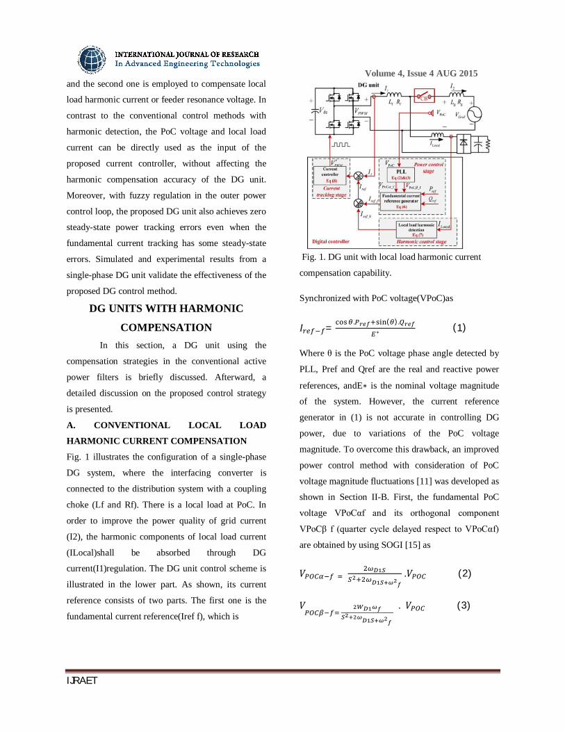
Fig. 1 illustrates the configuration of a single-phase
DG system, where the interfacing converter is
connected to the distribution system with a coupling
choke (Lf and Rf). There is a local load at PoC. In
order to improve the power quality of grid current
(I2), the harmonic components of local load current
(ILocal)shall be absorbed through DG
current(I1)regulation. The DG unit control scheme is
illustrated in the lower part. As shown, its current
reference consists of two parts. The first one is the
fundamental current reference(Iref f), which is
Fig. 1. DG unit with local load harmonic current
compensation capability.
Synchronized with PoC voltage(VPoC)as
퐼 = . ( ).
∗ (1)
Where θ is the PoC voltage phase angle detected by
PLL, Pref and Qref are the real and reactive power
references, andE∗ is the nominal voltage magnitude
of the system. However, the current reference
generator in (1) is not accurate in controlling DG
power, due to variations of the PoC voltage
magnitude. To overcome this drawback, an improved
power control method with consideration of PoC
voltage magnitude fluctuations [11] was developed as
shown in Section II-B. First, the fundamental PoC
voltage VPoCαf and its orthogonal component
VPoCβ f (quarter cycle delayed respect to VPoCαf)
are obtained by using SOGI [15] as
푉 .푉 (2)
푉
. 푉 (3)

Volume 4, Issue 4 AUG 2015
IJRAET
whereωD1 is the cutoff bandwidth of SOGI and ωf is
the fundamental angular frequency. For a single-
phase DG system, relationships between the power
reference and the fundamental reference current can
be established in the artificial stationaryα − β
reference frame as follows:
푃 . (푉 _ . _ _
.
퐼 _ ) (4)
푄 . (푉 _ . 퐼 _ - 푉 _ .
퐼 _ ) (5)
Where I α_ and I β_ are the DG fundamental
current reference and its orthogonal component in the
artificialα − βreference frame. Similarly, VPoCαf and
VPoCβ f are PoC fundamental voltage and its
orthogonal component, respectively. According to (4)
and (5), the instantaneous fundamental current
reference(Iref f)of a single-phase DG unit can be
obtained as
퐼 _ = 퐼 _ = ( _ . _ . )
_ _ (6) .
Moreover, to absorb the harmonic current of local
nonliear load, the DG harmonic current reference(Iref
h)is produced
퐼 _ (푆). 퐼 =
∑
, , , ….. . 퐼 (7)
Where GD(s)is the transfer function of the harmonic
extractor. To realize selective harmonic
compensation performance [24], [25],GD(s)is
designed to have a set of bandpass filters with cutoff
frequencyωD2. With the derived fundamental and
harmonic current references, the DG current
reference is written asIref =Iref_f + Iref_h.
Afterward, the proportional and multiple resonant
controllers [12], [18]–[20] are adopted to ensure
rapid current tracking
푉∗ = 퐺 (푠) . (퐼 − 퐼 )
= (퐾 + ∑ , , ,……, ).( 퐼 _ +
퐼 _ -퐼 ) (8)
Where V∗P is the reference voltage for pulse width
modulation (PWM) processing, Kp the proportional
gain of the current controller Gcur(s),Kih the
resonant controller gain at the order h, ωc the cutoff
frequency of the resonant controller, and ωhis the
angular frequency at fundamental and selected
harmonic frequencies.
B. CONVENTIONAL FEEDER RESONANCE
VOLTAGE COMPENSATION
It should be pointed out that the objective of local
load harmonic compensation is to ensure sinusoidal
grid currentI2 in Fig. 1. In this control mode, DG unit
should not actively regulate the PoC voltage quality.
As a result, the PoC voltage can be distorted
especially when it is connected to the main grid
through a long underground cable with nontrivial
parasitic capacitance [8], [23]. In this case, the feeder
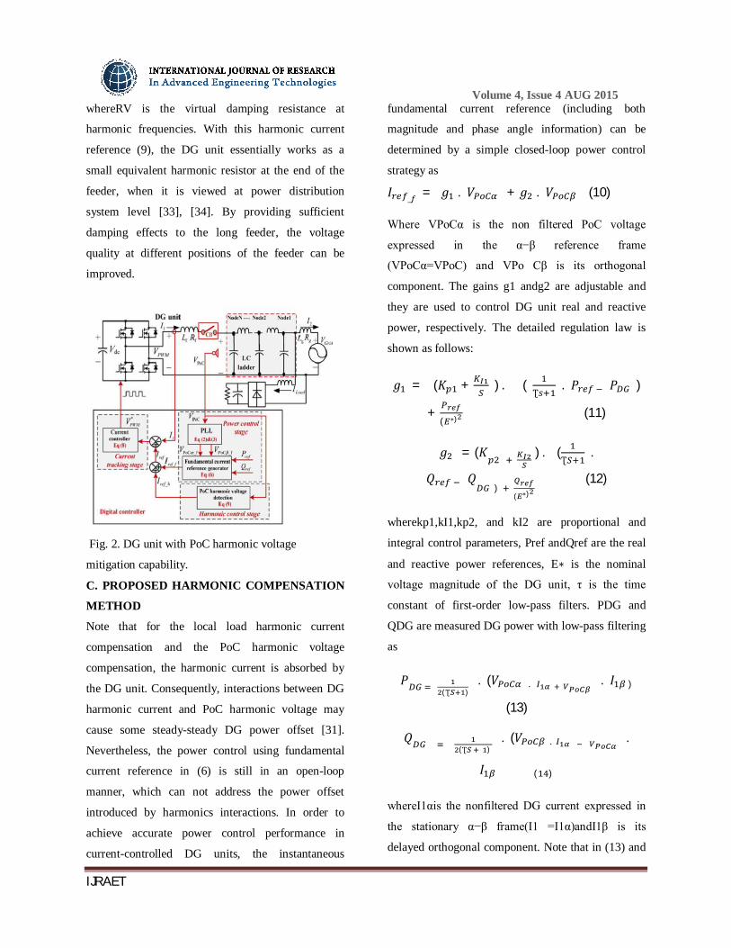
is often modeled by anLCladder [23], [26]. To
address the resonance issue associated with long
underground cables, the R-APF concept can also be
embedded in the DG unit current control, as
illustrated in Fig. 2. Compared to Fig. 1, the DG
harmonic current reference in this case is modified as
퐼 _ = (- ) . (퐺 (S) . 푉 ) (9)
Volume 4, Issue 4 AUG 2015
IJRAET
whereRV is the virtual damping resistance at
harmonic frequencies. With this harmonic current
reference (9), the DG unit essentially works as a
small equivalent harmonic resistor at the end of the
feeder, when it is viewed at power distribution
system level [33], [34]. By providing sufficient
damping effects to the long feeder, the voltage
quality at different positions of the feeder can be
improved.
Fig. 2. DG unit with PoC harmonic voltage
mitigation capability.
C. PROPOSED HARMONIC COMPENSATION
METHOD
Note that for the local load harmonic current
compensation and the PoC harmonic voltage
compensation, the harmonic current is absorbed by
the DG unit. Consequently, interactions between DG
harmonic current and PoC harmonic voltage may
cause some steady-steady DG power offset [31].
Nevertheless, the power control using fundamental
current reference in (6) is still in an open-loop
manner, which can not address the power offset
introduced by harmonics interactions. In order to
achieve accurate power control performance in
current-controlled DG units, the instantaneous
fundamental current reference (including both
magnitude and phase angle information) can be
determined by a simple closed-loop power control
strategy as
퐼 _ = 푔 . 푉 + 푔 . 푉 (10)
Where VPoCα is the non filtered PoC voltage
expressed in the α−β reference frame
(VPoCα=VPoC) and VPo Cβ is its orthogonal
component. The gains g1 andg2 are adjustable and
they are used to control DG unit real and reactive
power, respectively. The detailed regulation law is
shown as follows:
푔 = (퐾 + ) . ( Ʈ
. 푃 푃 )
+ ( ∗) (11)
푔 = (퐾 ) . (Ʈ
.
푄 푄 ) ( ∗)
(12)
wherekp1,kI1,kp2, and kI2 are proportional and
integral control parameters, Pref andQref are the real
and reactive power references, E∗ is the nominal
voltage magnitude of the DG unit, τ is the time
constant of first-order low-pass filters. PDG and
QDG are measured DG power with low-pass filtering
as
푃 (Ʈ ) . (푉 .
. 퐼 )
(13)
푄 (Ʈ ) . (푉 . .
퐼 ( )
whereI1αis the nonfiltered DG current expressed in
the stationary α−β frame(I1 =I1α)andI1β is its
delayed orthogonal component. Note that in (13) and
Volume 4, Issue 4 AUG 2015
IJRAET
(14), the power offset caused by harmonic voltage
and harmonic current interactions is also considered.
Although the proposed closed-loop power control
method eliminates power tracking errors, it can be
seen that the fundamental current reference in (10)
will be distorted if PoC voltage has some ripples.
When it is applied to the current controller in (8), the
distorted fundamental current reference will affect
the performance of DG harmonic current tracking. To
overcome this drawback, an improved proportional
and resonant controller with two control branches is
proposed as
퐼 _ =
⎩⎪⎨
⎪⎧
−
퐼 , 푉
푅 , Feeder resonance voltage compensation0, DG harmonic current rejection
(16)
MODELING OF DG UNIT WITH THE
PROPOSED CURRENT CONTROL
SCHEME
In this section, the harmonic compensation
performance using the proposed current controller is
investigated.
A. Modeling of the Proposed Current Control
Method : It is well understood that the current-
controlled inverter shall be described as a closed-loop
Norton equivalent circuit [27], [29]
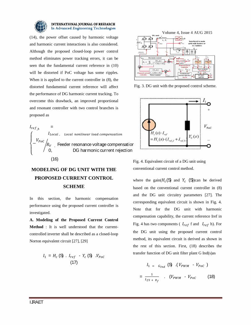
퐼 = 퐻 (S) . 퐼 - 푌 (S) .푉 (17)
Fig. 3. DG unit with the proposed control scheme.
Fig. 4. Equivalent circuit of a DG unit using
conventional current control method.
where the gain(퐻 (S) and 푌 (S))can be derived
based on the conventional current controller in (8)
and the DG unit circuitry parameters [27]. The
corresponding equivalent circuit is shown in Fig. 4.
Note that for the DG unit with harmonic
compensation capability, the current reference Iref in
Fig. 4 has two components ( 퐼 f and 퐼 h). For
the DG unit using the proposed current control
method, its equivalent circuit is derived as shown in
the rest of this section. First, (18) describes the
transfer function of DG unit filter plant G Ind(s)as
퐼 (S) .( 푉 - 푉 )
=
. (푉 - 푉 (18)

Volume 4, Issue 4 AUG 2015
IJRAET
Where Lf is the inductance of the DG coupling choke
and Rf is its stray resistance. VPWM is the average
inverter output voltage. Additionally, the delay of DG
control [28] is written as
푉 = 푒 . . . 푉∗ (19)
Where Td is the sampling period of the system. Note
that the delay here includes one sampling period
processing delay and half sampling period voltage
modulation delay.
Fig. 5. Equivalent circuit of a DG unit using the
proposed current control method.
By solving (15), (18), and (19), the closed-loop DG
current response can be given as
퐼 = 퐻 (S) . 퐼 _f + 퐻 (S) . 퐼 _ - 푌 (S) .푉 (20)
Where Hf(s) and Hh(s) represent the closed-loop
response of DG unit current to fundamental and
harmonic current references, respectively.
YP(s)demonstrates the sensitivity of DG line current
tracking to PoC voltage disturbances [27]. The
detailed expression of terms in (20) is listed .For the
DG unit with the proposed current control scheme, a
modified Norton equivalent circuit with two
controlled current sources can be applied to
demonstrate the unique behavior of the proposed
controller. As illustrated in Fig. 5, the current source
Hf(s)Iref f is responsible for regulating DG unit
fundamental current. Additionally, the current
sourceHh(s)Iref h aims to compensate system
harmonics at selected harmonic frequencies.
FUZZY LOGIC CONTROLLER
In FLC, basic control action is determined
by a set of linguistic rules. These rules are
determined by the system. Since the numerical
variables are converted into linguistic variables,
mathematical modeling of the system is not required
in FC. The FLC comprises of three parts:
fuzzification, interference engine and defuzzification.
The FC is characterized as i. seven fuzzy sets for
each input and output. ii. Triangular membership
functions for simplicity. iii. Fuzzification using
continuous universe of discourse. iv. Implication
using Mamdani’s, ‘min’ operator. v. Defuzzification
using the height method.
Fuzzification: Membership function values are
assigned to the linguistic variables, using seven fuzzy
subsets: NB (Negative Big), NM (Negative Medium),
NS (Negative Small), ZE (Zero), PS (Positive Small),
PM (Positive Medium), and PB (Positive Big). The
Fig.(a) Fuzzy logic controller

Volume 4, Issue 4 AUG 2015
IJRAET
partition of fuzzy subsets and the shape of
membership CE(k) E(k) function adapt the shape up
to appropriate system. The value of input error and
change in error are normalized by an input scaling
factor
Table I Fuzzy Rules
Change
in error
Error
NB NM NS Z PS PM PB
NB PB PB PB PM PM PS Z
NM PB PB PM PM PS Z Z
NS PB PM PS PS Z NM NB
Z PB PM PS Z NS NM NB
PS PM PS Z NS NM NB NB
PM PS Z NS NM NM NB NB
PB Z NS NM NM NB NB NB
In this system the input scaling factor has been
designed such that input values are between -1 and
+1. The triangular shape of the membership function
of this arrangement presumes that for any particular
E(k) input there is only one dominant fuzzy subset.
The input error for the FLC is given as
E(k) = ( ) ( )
( ) ( ) (10)
CE(k) = E(k) – E(k-1) (11)
Fig.(b) Membership functions
Inference Method: Several composition methods
such as Max–Min and Max-Dot have been proposed
in the literature. In this paper Min method is used.
The output membership function of each rule is given
by the minimum operator and maximum operator.
Table 1 shows rule base of the FLC.
Defuzzification: As a plant usually requires a non-
fuzzy value of control, a defuzzification stage is
needed. To compute the output of the FLC, „height‟
method is used and the FLC output modifies the
control output. Further, the output of FLC controls
the switch in the inverter. In UPQC, the active power,
reactive power, terminal voltage of the line and
capacitor voltage are required to be maintained. In
order to control these parameters, they are sensed and
compared with the reference values. To achieve this,
the membership functions of FC are: error, change in
error and output
The set of FC rules are derived from
u=-[αE + (1-α)*C]
Where α is self-adjustable factor which can regulate
the whole operation. E is the error of the system, C is
the change in error and u is the control variable. A
large value of error E indicates that given system is
not in the balanced state. If the system is unbalanced,
the controller should enlarge its control variables to
Volume 4, Issue 4 AUG 2015
IJRAET
balance the system as early as possible. One the other
hand, small value of the error E indicates that the
system is near to balanced state. Overshoot plays an
important role in the system stability. Less overshoot
is required for system stability and in restraining
oscillations. During the process, it is assumed that
neither the UPQC absorbs active power nor it
supplies active power during normal conditions. So
the active power flowing through the UPQC is
assumed to be constant. The set of FC rules is made
using Fig.(b) is given in Table 1.
SIMULATED RESULTS
In order to verify the correctness of the
proposed control strategy, simulated and
experimental results are obtained from a single-phase
DG unit.
A. SIMULATED RESULTS
1) Compensation of Local Nonlinear Loads: First, the
DG unit with a local diode rectifier load is tested in
the simulation. The configuration of the system is the
same as shown in Fig. 1, and PoC is connected to a
stiff controlled voltage source (to emulate the main
grid) with nominal 50 Hz frequency. The main grid
voltage contains 2.8% third and 2.8% fifth harmonic
voltages. In this simulation, the reference power is set
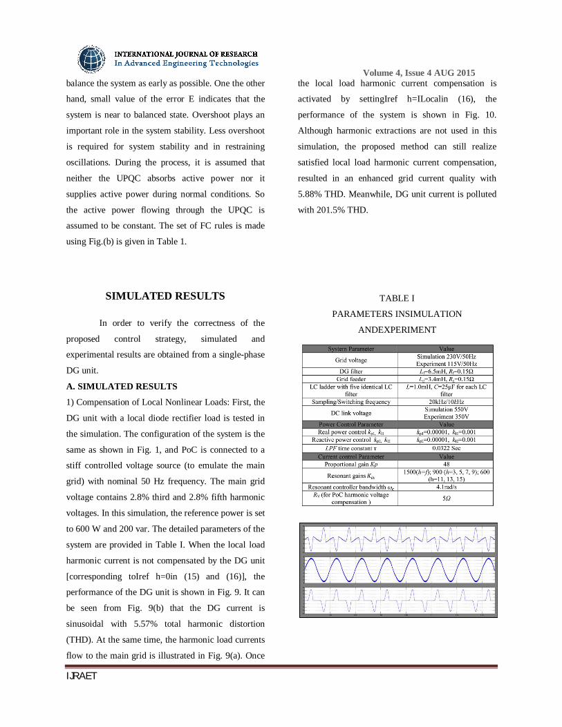
to 600 W and 200 var. The detailed parameters of the
system are provided in Table I. When the local load
harmonic current is not compensated by the DG unit
[corresponding toIref h=0in (15) and (16)], the
performance of the DG unit is shown in Fig. 9. It can
be seen from Fig. 9(b) that the DG current is
sinusoidal with 5.57% total harmonic distortion
(THD). At the same time, the harmonic load currents
flow to the main grid is illustrated in Fig. 9(a). Once
the local load harmonic current compensation is
activated by settingIref h=ILocalin (16), the
performance of the system is shown in Fig. 10.
Although harmonic extractions are not used in this
simulation, the proposed method can still realize
satisfied local load harmonic current compensation,
resulted in an enhanced grid current quality with
5.88% THD. Meanwhile, DG unit current is polluted
with 201.5% THD.
TABLE I
PARAMETERS INSIMULATION
ANDEXPERIMENT
Volume 4, Issue 4 AUG 2015
IJRAET
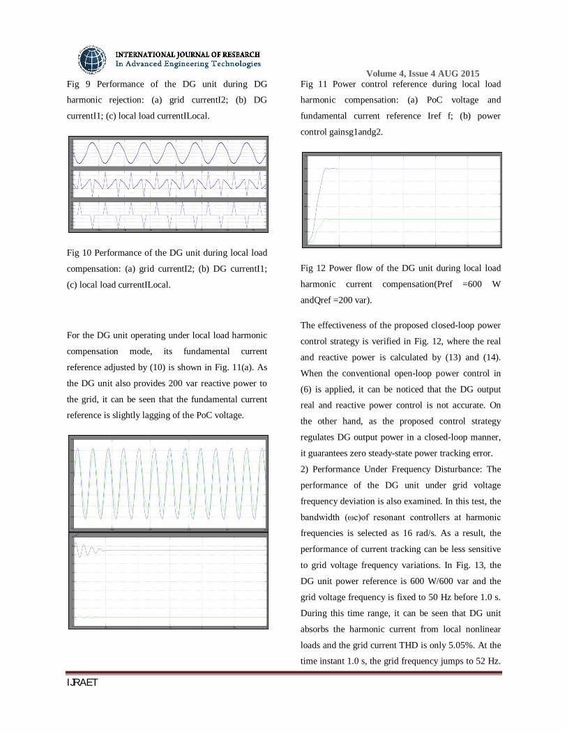
Fig 9 Performance of the DG unit during DG
harmonic rejection: (a) grid currentI2; (b) DG
currentI1; (c) local load currentILocal.
Fig 10 Performance of the DG unit during local load
compensation: (a) grid currentI2; (b) DG currentI1;
(c) local load currentILocal.
For the DG unit operating under local load harmonic
compensation mode, its fundamental current
reference adjusted by (10) is shown in Fig. 11(a). As
the DG unit also provides 200 var reactive power to
the grid, it can be seen that the fundamental current
reference is slightly lagging of the PoC voltage.
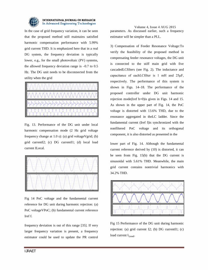
Fig 11 Power control reference during local load
harmonic compensation: (a) PoC voltage and
fundamental current reference Iref f; (b) power
control gainsg1andg2.
Fig 12 Power flow of the DG unit during local load
harmonic current compensation(Pref =600 W
andQref =200 var).
The effectiveness of the proposed closed-loop power
control strategy is verified in Fig. 12, where the real
and reactive power is calculated by (13) and (14).
When the conventional open-loop power control in
(6) is applied, it can be noticed that the DG output
real and reactive power control is not accurate. On
the other hand, as the proposed control strategy
regulates DG output power in a closed-loop manner,
it guarantees zero steady-state power tracking error.
2) Performance Under Frequency Disturbance: The
performance of the DG unit under grid voltage
frequency deviation is also examined. In this test, the
bandwidth (ωc)of resonant controllers at harmonic
frequencies is selected as 16 rad/s. As a result, the
performance of current tracking can be less sensitive
to grid voltage frequency variations. In Fig. 13, the
DG unit power reference is 600 W/600 var and the
grid voltage frequency is fixed to 50 Hz before 1.0 s.
During this time range, it can be seen that DG unit
absorbs the harmonic current from local nonlinear
loads and the grid current THD is only 5.05%. At the
time instant 1.0 s, the grid frequency jumps to 52 Hz.
Volume 4, Issue 4 AUG 2015
IJRAET
In the case of grid frequency variation, it can be seen
that the proposed method still maintains satisfied
harmonic compensation performance with 5.99%
grid current THD. It is emphasized here that in a real
DG system, the frequency deviation is typically
lower, e.g., for the small photovoltaic (PV) systems,
the allowed frequency deviation range is –0.7 to 0.5
Hz. The DG unit needs to be disconnected from the
utility when the grid
Fig. 13. Performance of the DG unit under local
harmonic compensation mode (2 Hz grid voltage
frequency change at 1.0 s): (a) grid voltageVgrid; (b)
grid currentI2; (c) DG currentI1; (d) local load
current ILocal.
Fig 14 PoC voltage and the fundamental current
reference for DG unit during harmonic rejection: (a)
PoC voltageVPoC; (b) fundamental current reference
Iref f.
frequency deviation is out of this range [35]. If very
larger frequency variation is present, a frequency
estimator could be used to update the PR control
parameters. As discussed earlier, such a frequency
estimator will be simpler than a PLL.
3) Compensation of Feeder Resonance Voltage:To
verify the feasibility of the proposed method in
compensating feeder resonance voltages, the DG unit
is connected to the stiff main grid with five
cascadedLCfilters (see Fig. 2). The inductance and
capacitance of eachLCfilter is 1 mH and 25μF,
respectively. The performance of this system is
shown in Figs. 14–18. The performance of the
proposed controller under DG unit harmonic
rejection mode(Iref h=0)is given in Figs. 14 and 15.
As shown in the upper part of Fig. 14, the PoC
voltage is distorted with 13.6% THD, due to the
resonance aggregated in theLC ladder. Since the
fundamental current (Iref f)is synchronized with the
nonfiltered PoC voltage and its orthogonal
component, it is also distorted as presented in the
lower part of Fig. 14. Although the fundamental
current reference derived by (10) is distorted, it can
be seen from Fig. 15(b) that the DG current is
sinusoidal with 5.61% THD. Meanwhile, the main
grid current contains nontrivial harmonics with
34.2% THD.
Fig 15 Performance of the DG unit during harmonic
rejection: (a) grid current I2; (b) DG currentI1; (c)
load current I .

Volume 4, Issue 4 AUG 2015
IJRAET
Fig 16 PoC voltage and its corresponding
fundamental current reference during feeder
resonance voltage compensation: (a) PoC
voltageVPoC; (b) fundamental current reference Iref
f.
When the feeder resonance voltage compensation is
enabled by controlling the DG unit as a virtual
resistance[RV =5in (16)] at selected harmonic
frequencies, corresponding responses of the system
are shown in Figs. 16 and 17. In contrast to the
performance in Fig. 14, it can be seen from Fig. 16
that the PoC
Fig 17 Performance of the DG unit during feeder
resonance voltage compensation: (a) grid currentI2;
(b) DG currentI1; (c) load currentILoad.
Fig 18 Power flow of the DG unit with LC ladder
(Pref =1000 W and Qref =0 var).
harmonic voltage in this case is mitigated and its
THD reduces to 3.07%. The associated current
waveforms during feeder resonance voltage
compensation are shown in Fig. 17. It is obvious that
DG current has more distortions (with 35.09% THD),
while the main grid current THD reduces to 8.12%.
Finally, the power flow performance of the DG unit
using the proposed power control scheme is shown in
Fig. 18. From the time range 0 to 1.0 s, the DG unit is
controlled to eliminate DG harmonic currents(Iref
h=0). From 1.0 to 1.5 s, feeder resonance voltage
compensation is slowly activated by changing RV
from infinity to 5Ω. It can be seen that the power
control is always accurate during the transitions
between different control modes.
CONCLUSION
In this paper, an easy harmonic
compensation strategy is projected for current-
controlled DG unit interfacing converters. By
separating the traditional proportional and multiple
resonant controllers into 2 parallel control branches,
the projected technique realizes power management
and harmonic compensation while not mistreatment
any native nonlinear load harmonic current extraction
or PoC harmonic voltage detection. Moreover, the
input of the elemental power management branch is
regulated by a closed-loop power management theme
,that avoids the adoption of PLLs. The projected
power management technique ensures correct power
management even once harmonic compensation tasks
ar activated within the DG unit or the PoC voltage
Volume 4, Issue 4 AUG 2015
IJRAET
changes with fuzzy logic controller. Simulated and
experimental results from a single-phase DG unit
verified the feasibleness of the projected strategy.
REFERENCES
[1] F. Blaabjerg, Z. Chen, and S. B. Kjaer, “Power
electronics as efficient interface in dispersed power
generation systems,” IEEE Trans. Power Electron,
vol. 19, no. 5, pp. 1184–1194, Sep. 2004.
[2] F. Wang, J. L. Duarte, M. A. M. Hendrix, and P.
F. Ribeiro, “Modeling and analysis of grid harmonic
distortion impact of aggregated DG inverters,” IEEE
Trans. Power Electron, vol. 26, no. 3, pp. 786–797,
Mar. 2011.
[3] L. Asiminoaei, F. Blaabjerg, S. Hansen, and P.
Thogersen, “Adaptive compensation of reactive
power with shunt active power filters,”IEEE Trans.
Ind. Appl., vol. 44, no. 3, pp. 867–877, May/Jun.
2008.
[4] L. Asiminoaei, F. Blaabjerg, and S. Hansen,
“Detection is key—Harmonic detection methods for
active power filter applications,”IEEE. Ind. Appl.
Mag., vol. 13, no. 4, pp. 22–33, Jul./Aug. 2007.
[5] N. Pogaku and T. C. Green, “Harmonic
mitigation throughout a distribution system: A
distributed-generator-based solution,” inIEE Proc.
Gener. Transm. Distrib., vol. 153, no. 3, pp. 350–358,
May 2006..
[6] C. J. Gajanayake, D. M. Vilathgamuwa, P. C.
Loh, R. Teodorescu, and F. Blaabjerg, “Z-source-
inverter-based flexible distributed generation system
solution for grid power quality improvement,” IEEE
Trans. Energy Convers., vol. 24, no. 3, pp. 695–704,
Sep. 2009.
[7] R. I. Bojoi, G. Griva, V. Bostan, M. Guerriero, F.
Farina, and F. Profumo, “Current control strategy of
power conditioners using sinusoidal signal integrators
in synchronous reference frame,”IEEE Trans. Power.
Electron., vol. 20, no. 6, pp. 1402–1412, Nov. 2005.
[8] T.-L. Lee and P.-T. Cheng, “Design of a new
cooperative harmonic filtering strategy for distributed
generation interface converters in an islanding
network,”IEEE Trans. Power Electron., vol. 22, no.
5, pp. 1919–1927, Sep. 2007.
[9] B. Han, B. Bae, H. Kim, and S. Baek, “Combined
operation of unified power-quality conditioner with
distributed generation,”IEEE Trans. Power Del., vol.
21, no. 1, pp. 330–338, Mar. 2003.
[10] M. Cirrincione, M. Pucci, and G. Vitale, “A
single-phase DG generation unit with shunt active
power filter capability by adaptive neural filtering,”
IEEE Trans. Ind. Electron, vol. 55, no. 5, pp. 2093–
2010, May 2008.
[11] R. I. Bojoi, L. R. Limongi, D. Roiu, and A.
Tenconi, “Enhanced power quality control strategy
for single-phase inverters in distributed generation
systems,”IEEE Trans. Power Electron., vol. 26, no. 3,
pp. 798–806, Mar. 2011.
[12] J. He, Y. W. Li, and S. Munir, “A flexible
harmonic control approach through voltage
controlled DG-Grid interfacing converters,”IEEE
Trans. Ind. Electron., vol. 59, no. 1, pp. 444–455,
Jan. 2012.
[13] B. P. Mcgrath, D. G. Holmes, and J. J. H.
Galloway, “Power converter line synchronization
using a discrete Fourier transform (DFT) based on a
variable sample rate,”IEEE Trans. Power Electron.,
vol. 20, no. 4, pp. 877–884, Apr. 2005.
[14] H. Akagi, Y. Kanazawa, and A. Nabae,
“Instantaneous reactive power compensation
comprising switching devices without energy storage
components,”IEEE Trans. Ind. Appl., vol. 20, no. 3,
pp. 625–630, Mar/Apr. 1984.

Volume 4, Issue 4 AUG 2015
IJRAET
[15] P. Rodr´ıguez, A. Luna, I. Candlea, R. Mujal, R.
Teodorescu, and F. Blaabjerg, “Multiresonant
frequency-locked loop for grid synchronization of
power converters under
KANDALA GANGA SAMPATH
Completed B.Tech. in Electrical & Electronics
Engineering in 2013 from JAGRUTI INSTITUTE
OF ENGINEERING AND TECHNOLOGY
Chintapalliguda, Ibrahimpatnam, Ranga Reddy,
Telangana, India Affiliated to JNTUH, and M.Tech
in Power Electronics in 2015 from KSHATRIYA
COLLEGE OF ENGINEERING Chepur, Armoor,
Nizamabad, Telangana, India Affiliated to JNTUH.E-
mail id: [email protected]
K.NAGARAJU Completed B.tech
in Electrical & Electronics Engineering in 2007 from
Vazir Sultan College of Engineering Affiliated to
Kakatiya University, and M.Tech in Embedded
Systems in 2011 from VNR VJIET Affiliated to
JNTUH. Working as Assistant Professor at
KSHATRIYA COLLEGE OF ENGINEERING
Chepur, Armoor, Nizamabad, Telangana, India. Area
of interest includes RTOS In Power Systems & Smart
Grid Technology.
E-mail id: [email protected]