a field study on pile response to blast-induced ground motion
TRANSCRIPT
†Corresponding author. Tel: +65 6790 5255
E-mail: [email protected]
A Field Study on Pile response to Blast-Induced Ground Motion
L.B. Jayasinghe1, Z.Y. Zhao1†, A.T.C. Goh1, H.Y. Zhou2, Y.L. Gui3, M. Tao4
1School of Civil and Environmental Engineering, Nanyang Technological University, Singapore
2Key Laboratory of Urban Security and Disaster Engineering of Ministry of Education, Beijing
University of Technology, China
3School of Civil Engineering and Geosciences, Newcastle University, UK
4School of Resources and Safety Engineering, Central South University, Changsha, China.
ABSTRACT
A series of field tests using controlled blasting was conducted at a location in the North
Western part of Singapore to assess the behaviour of pile foundations subjected to ground
excitation. The field tests involved three piles with different pile head fixity conditions. The
piles were instrumented with strain gauges to evaluate the bending moments and axial force
along the piles. For the fixed-head piles, the maximum bending moment occurred at the pile
head level. For free-head pile exhibited higher bending moments close to the mid-height of
the pile and zero bending moment at the pile head due to the absence of restraints at the top.
For all cases, the axial force was maximum value at the pile head.
Keywords: Rock blasting; Field tests; Piles; Ground vibration; Strain
1. Introduction
In a construction blasting operation, the main function of explosives is to break the rocks
through the release of large amounts of energy. However, only a portion of the energy is
consumed in breaking the rocks and the remaining energy is dissipated in the form of seismic
waves expanding rapidly outward from the blast as ground vibrations and air blast. Ground
vibrations from rock blasting are a particular concern as the vibration which has a high
amplitude and short duration can cause damage to nearby structures in one or several ways.
For example, blasting induced ground vibration may compact the foundation soil on which
the structure is built, resulting in distress to the structure. When the natural frequency of the
2
structural member(s) coincides with the frequency of the impinging ground vibrations,
resonant vibrations are produced and cause substantial damage to the structure. In addition,
ground vibrations which have high frequency and high amplitude may also have an impact on
the various components of the structure so that the strength of the member or material is
exceeded. Moreover, soil can be liquefied beneath or adjacent to the structure as a result of
blasting, resulting in substantial damage to foundations and consequently to the
superstructure.
Generally, for the safer performance of any structure, the foundation should have sufficient
strength and stability. Nowadays, high-rise buildings, bridges and other smart infrastructures
depend largely on the pile foundation for transferring the heavy loads from the superstructure
above through weak compressible soil strata into deeper, competent soil layers which have
adequate capacity to carry these loads. In engineering practice, many piles are designed only
for carrying vertical loading, as typically the vertical loads (from the gravity weight of the
structure) are significantly larger than the horizontal loads such as wind loading. Short
duration, high frequency and high amplitude loads such as ground vibrations from rock
blasting may also have an impact on the pile foundation system. They can induce lateral and
bending stresses in the piles and cause significant damage, resulting in differential settlement
and tilting of the superstructure, leading to weakening of the structure [1]. A small magnitude
of a blast, if it occurs in close proximity of a pile, it may cause the pile to fail which can
subsequently lead to progressive failure of the whole structure [2, 3]. It is therefore important
when designing structures that may be subjected to the ground vibrations from rock blasting
to assess the stability and vulnerability of a pile foundation system against ground-borne
vibrations.
The influences of ground vibration on pile foundations have been studied by researchers
using small-scale experiments and numerical simulations. Abdoun et al. [4] and Wilson et al.
[5] carried out small-scale centrifuge tests to study the dynamic response of pile foundations
in liquefying sand during seismic loading. Shim [6] also has carried out a series of 70-g
centrifuge tests to investigate the blast wave propagation and response of piles embedded in
saturated sand. Aluminium piles with hollow circular section at different standoff distances
from buried the explosive charge were used in the test. Kamijo et al. [7] conducted vibration
tests at a large-scale mining site to investigate liquefaction phenomena and dynamic
responses of pile foundations. Ground motions from large-scale blasting operations were used
3
for the vibration tests. It is found that bending moments were maximum at the pile heads,
regardless of input motion levels. However, the moment distribution shapes differed with the
degree of the liquefaction in the test pit Ashford et al. [8] conducted full-scale tests to assess
the dynamic response of a single pile, a four-pile group, and a nine-group subjected to lateral
spreading. The steel pipes were 11.5m long with an outer diameter of 318mm and thickness
of 10.5mm. The test results indicated that the pile head displacement and moment in the
single pile were significantly higher than those observed in the pile groups. It is also found
that the degree of fixity at the pile tips had a great influence on the moments of individual
piles in the group. Large bending moments are developed in the pile when the larger degree
of fixity into the dense soil layer. Durante et al. [9] performed 1-g shaking table tests to
investigate the dynamic response of a single pile and a pile group subjected to both horizontal
and vertical dynamic shaking. The studies have shown that the kinematic interaction may be
significant near the pile head if rotations are prevented and close by the interface between soil
layers with different stiffness [10-12].
A number of researchers have developed numerical methods to analyse the performance of
pile foundations subjected to dynamic lateral loads [13-17]. Hao et al. [18] presented a
numerical method to calculate the elastic and inelastic single pile responses to blast loads.
The pile-soil system was modelled as beam-column elements supported by both vertical soil
springs of Winkler foundation. However, this method cannot incorporate the radial and three-
dimensional components of interaction. The shear stress which is acting along the side of the
pile is ignored by this method. Since a 3D FE analysis requires a considerable amount of
computational cost for generating input and interpretation results, it has not been used
frequently until recently for the soil-pile interaction analyses. Huang et al. [19] studied the
dynamic response of pile-soil-structure interaction (PSSI) system under blasting load. Solid
elements were used to simulate piles, soil and pile cap, while beam elements were used to
simulate columns and beams of the superstructure. In this study, they applied a velocity-time
history curve of blasting seismic wave on the tip of the pile. The authors have concluded that
because of the maximum shear stress at the top of the pile, the connection of piles and pile
cap are easily damaged and pile-soil contact pressure increases at the pile ends. Jayasinghe et
al. [20] developed a fully coupled method to treat the blast response of a pile foundation in
saturated soil and the effects of end restraint of pile head and the number and spacing of piles
within a group were investigated later [21].

4
The objective of the present study is to investigate the impact of rock blasting on pile
foundations. Thus, a series of field tests was conducted at a location in the north western part
of Singapore to study the pile response and possible damage when subjected to ground
excitation of various intensities. In this paper, a brief description of the test set-up and the pile
instrumentation is presented first. Then, the measured results and the calculated bending
moments and axial forces are presented and discussed.
2. Test set-up
In Singapore, bored cast-in-situ concrete piles are commonly used as the foundation for high-
rise buildings. Chang and Broms [22] reported that approximately 200000 to 400000 m
length of large diameter bored piles are installed in Singapore each year, because of the high
capacity, relatively low costs, easy length adjustment, and low noise and vibration levels
during construction. The diameters of these piles vary from 600 mm to 1500 mm depending
on the design load on the pile. The piles can be end-bearing piles, friction piles or a
combination of end bearing and friction piles. Socketed piles are widely used in the
Singapore construction industry as well as all over the world. Socketed piles are usually end-
bearing piles which are socketed into a weathered/soft rock. Socketing piles into a soft or
weathered rock will improve the axial and lateral load capacities of piles when the
surrounding soil above the rock is weak.
Before the field blast tests, soil investigation works were carried out to establish the
subsurface ground conditions. The layout of the test site is shown in Fig. 1. The test site
consisted of medium-grained granite bedrock, overlain by residual soils [23]. The rock-cores
retrieved from the boreholes, indicated the occurrence of Bukit Timah Granite rocks [24].
The slightly weathered granite G (II), was encountered at depths of between 0.6 m and 11 m
below the ground level.
In the field test, three instrumented bored cast-in-situ concrete piles (1 single pile and a pile
group of 2 piles) were used to investigate the response of piles subjected to rock blasting
induced ground vibration. All the piles were 600mm in diameter, and an average length of
8m. Two piles (pile A and C) were socketed into rock while the other one (pile B) was
embedded in soil. Moreover, two piles (pile A and B) had pile caps to prevent the rotation at
pile head and the other pile (pile C) had a free end at the pile head level. The dimensions of

5
the pile caps were 1.5m (width) x 1.5m (length) x 0.9m (height). A ground beam which has
cross section of 0.5m x 0.5m was used to connect the pile A and B.
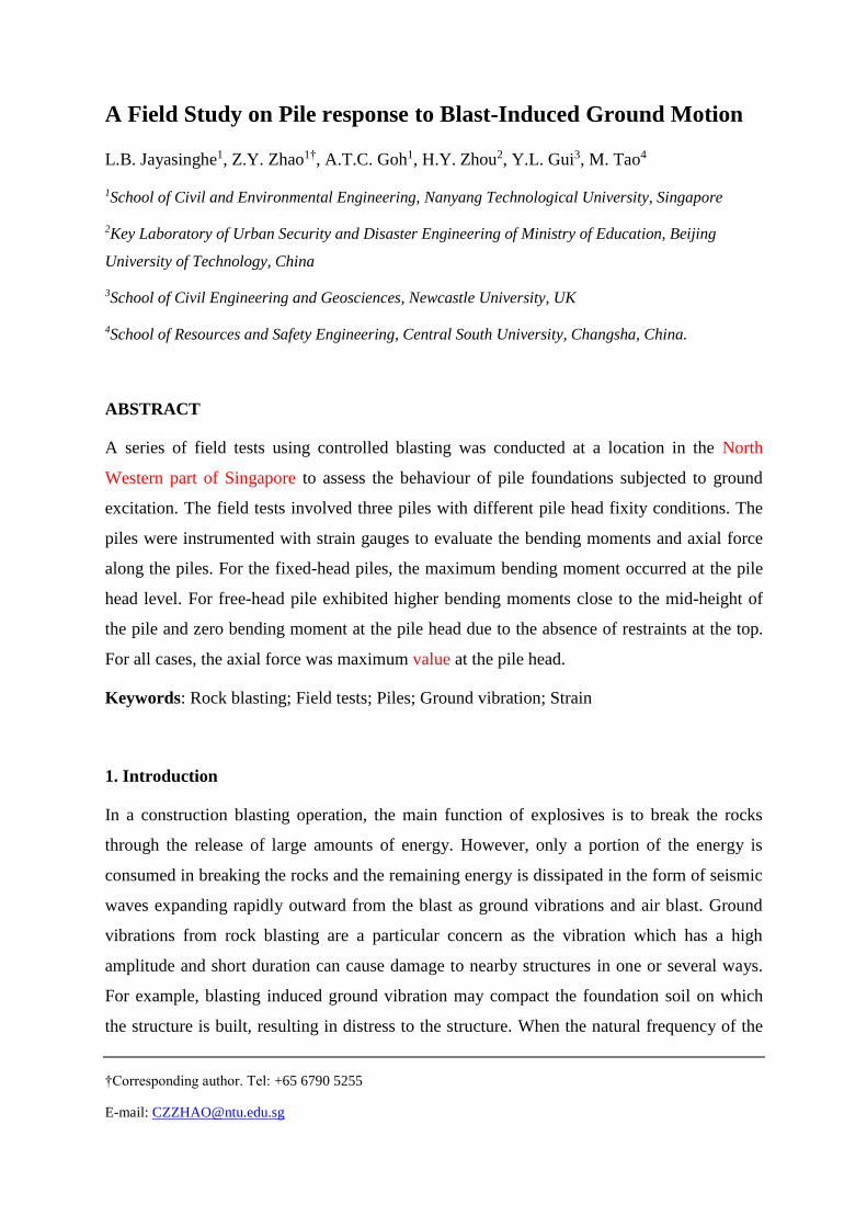
The compressive strength of the concrete was 53.7 N/mm2 at 28 days and all the piles were
nominally reinforced with 8 numbers of 16mm diameter of high strength deformed bars
(characteristics strength of 460 N/mm2) for the main vertical bars and 10mm diameter of high
strength deformed bars (characteristics strength of 460 N/mm2) at 200mm centre to centre
spacing for the stirrups as shown in Fig. 2.
Fig. 1. Plan and section view of the piles and blast holes locations (units of meters)
6
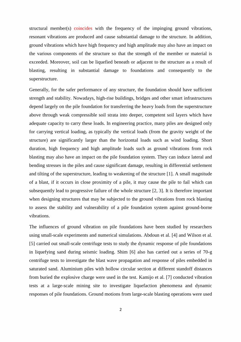
Fig. 2. Pile reinforcement details
In total, six numbers of blast tests were carried out as summarized in Table 1. The first 2 blast
tests (B0 and B1) were carried out to check and test the data logger’s settings, and the
remaining four blast tests (B2, B3, B3A and B4) were conducted to study the pile response
under blast-induced ground vibration. The sequence of the tests was B0, B1, B2, B3, B3A
and B4, respectively. Each blast hole was 76 mm in diameter and the explosives used in the
tests were Ammonium Nitrate-Fuel Oil (ANFO). The detonator used in the test was an
electronic detonator. Also shown in Fig. 2 are the locations of the blast holes (denoted by the
notations B0, B1 etc.). All the distances are measured from the reference borehole C (BH C),
which was used in the soil investigation works.
Table 1. Summary of blast tests
Blast test Distance from
BH C (m)
No. of
holes
ANFO
weight (kg)
B0 1 1 6.25
B1 2 1 12.5
B2 5 1 24
B3 8 2 58.1
B3A 3 3 84.9
B4 8 6 168.5
7
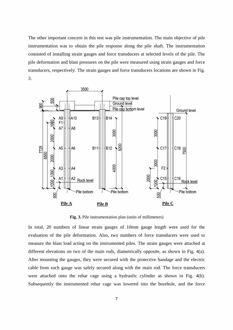
The other important concern in this test was pile instrumentation. The main objective of pile
instrumentation was to obtain the pile response along the pile shaft. The instrumentation
consisted of installing strain gauges and force transducers at selected levels of the pile. The
pile deformation and blast pressures on the pile were measured using strain gauges and force
transducers, respectively. The strain gauges and force transducers locations are shown in Fig.
3.
Fig. 3. Pile instrumentation plan (units of millimeters)
In total, 20 numbers of linear strain gauges of 10mm gauge length were used for the
evaluation of the pile deformation. Also, two numbers of force transducers were used to
measure the blast load acting on the instrumented piles. The strain gauges were attached at
different elevations on two of the main rods, diametrically opposite, as shown in Fig. 4(a).
After mounting the gauges, they were secured with the protective bandage and the electric
cable from each gauge was safely secured along with the main rod. The force transducers
were attached onto the rebar cage using a hydraulic cylinder as shown in Fig. 4(b).
Subsequently the instrumented rebar cage was lowered into the borehole, and the force
Pile A Pile C Pile B

8
transducers were extended into the borehole soil surface connecting a hydraulic hand pump to
a hydraulic cylinder. 10 numbers of strain gauges (A1 to A10 in Fig. 3) were installed on the
pile A at 1m, 2m, 4m, 6m and 7m heights from the pile bottom. 4 (B11 to B14) and 6 (C15 to
C20) numbers of strain gauges were attached on the pile B and pile C, respectively, at 1m,
4m and 7m heights from the pile bottom as illustrated in Fig. 3. The force transducers, F1 and
F2 (in Fig. 3), were installed on the pile A and pile C at 6.55m and 2m height from the pile
bottom, respectively.
(a) (b)
Fig. 4. Pile instrumentation (a) strain gauges on two main rods (b) force transducer fixture
3. Results and Discussion
As described above, a total of 3 piles were instrumented with electrical resisting foil-type
strain gauges. When the instrumented pile is deformed, the foil experiences a variation in
electrical resistance, which varies linearly with strain. All strain gauges were calibrated and
zeroed before each test. The strain gauges were attached at different elevations on the two of
the main rods at opposite sides of the piles as illustrated in Fig. 5 to obtain the strains from
which the bending moments and axial force along the lengths of the piles could be
determined. If the pile is subjected to axial deformation only, the strains on both sides of pile
must be same (i.e. ε1 = ε2 = ε). However, if the pile is subjected to bending deformation only,
the strains on both sides along the pile will be symmetric (i.e. ε1 = -ε2 = ε). Since the piles are
subjected to both bending and axial deformations by blasting induced ground vibration, the
strain gauges readings at the opposite sides of the piles (ε1 and ε2 in Fig. 5) are not the same.
Strain gauges with protective bandage
Hydraulic cylinder
Force transducer

9
Thus, the deformations are generated by both bending moment (εBM) and axial force (εAF) are
calculated as given in Eqs. (1) and (2).
(a) (b)
Fig. 5. (a) Strain gauges at the two main rods at opposite sides of the pile (b) typical strain responses
of the strain gauges
εBM =ε1−ε2
2 (1)
εAF =ε1+ε2
2 (2)
Considering the elasticity of the pile and from beam theory, the bending moment (BM) and
axial force (AF) are evaluated using the measured bending and axial strains as given in Eqs.
(3) and (4).
𝐵M =ε1−ε2
2 EpIp (
2
𝐷) (3)
𝐴𝐹 =ε1+ε2
2 EpA𝑝 (4)
In the above equations, Ep, Ip, Ap and D are the elastic modulus, the second moment of area,
the cross sectional area and the diameter of the pile, respectively.
Pile A had 10 strain gauges to investigate the vertical distributions of pile bending moments
and axial forces. Piles B and C had 4 and 6 strain gauges, respectively, to compare their

10
response with pile A. Fig. 5 show some typical strain time-histories measured at 4m height
from the pile bottom of each pile for B3 blast test. A5 and A6, B11 and B12, and C17 and
C18 strain gauges were installed at 4m height from the pile bottom on the two main rods at
opposite sides of pile A, pile B and pile C, respectively (Fig. 3). Pile A was the leading pile
of the 2-pile group while pile B was the trailing pile of the group and pile C was the single
pile with no pile cap at the pile head. As shown in Fig. 6, the strains measured in strain
gauges appear almost symmetrical with respect to the horizontal axis and in the opposite
phase, which suggests the pure bending of the pile. In addition, when the ground vibration
stops, the strain time-histories show a residual deformation that produces a residual bending
moment and axial force. The corresponding bending moments of each pile are shown in Fig.
7.
(a)
(b)

11
(c)
Fig. 6. Measured strain time-histories at 4m height from pile bottom of (a) pile A (b) pile B (c) pile C
for B3 blast test
Fig. 7. Time-histories of computed bending moments at 4m height from pile bottom of each pile for
B3 blast test
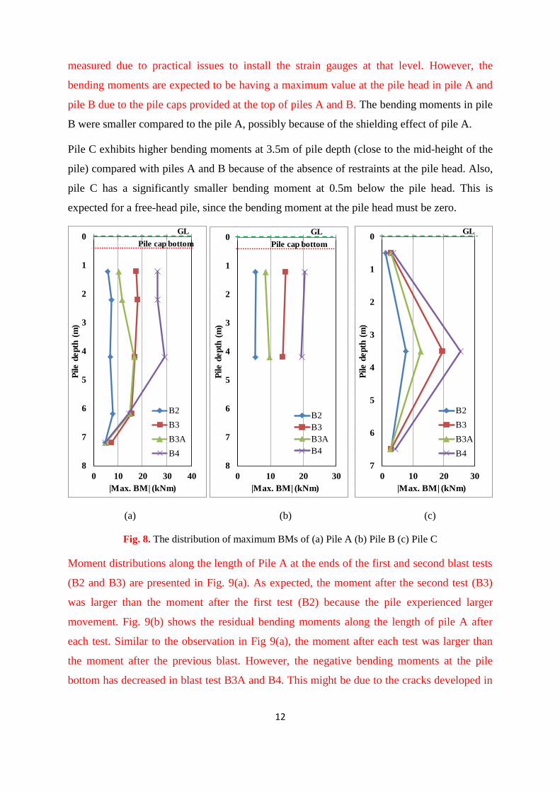
As described above, the measured ground vibrations in all the sensors from blast tests B2, B3,
B3A and B4 were used to study the pile response under blast-induced ground vibration. Fig.
8 shows the distribution of the maximum bending moments of each pile along the pile length.
The horizontal green colour dashed line and red colour dotted line in the plots indicate the
ground level (GL) and pile cap bottom level, respectively. It can be seen that the moment
distribution shapes differed in each test. Bending moments at the pile cap level could not be
12
measured due to practical issues to install the strain gauges at that level. However, the
bending moments are expected to be having a maximum value at the pile head in pile A and
pile B due to the pile caps provided at the top of piles A and B. The bending moments in pile
B were smaller compared to the pile A, possibly because of the shielding effect of pile A.
Pile C exhibits higher bending moments at 3.5m of pile depth (close to the mid-height of the
pile) compared with piles A and B because of the absence of restraints at the pile head. Also,
pile C has a significantly smaller bending moment at 0.5m below the pile head. This is
expected for a free-head pile, since the bending moment at the pile head must be zero.
(a) (b) (c)
Fig. 8. The distribution of maximum BMs of (a) Pile A (b) Pile B (c) Pile C
Moment distributions along the length of Pile A at the ends of the first and second blast tests
(B2 and B3) are presented in Fig. 9(a). As expected, the moment after the second test (B3)
was larger than the moment after the first test (B2) because the pile experienced larger
movement. Fig. 9(b) shows the residual bending moments along the length of pile A after
each test. Similar to the observation in Fig 9(a), the moment after each test was larger than
the moment after the previous blast. However, the negative bending moments at the pile
bottom has decreased in blast test B3A and B4. This might be due to the cracks developed in
0
1
2
3
4
5
6
7
8
0 10 20 30 40
Pile
de
pth
(m
)
|Max. BM| (kNm)
B2
B3
B3A
B4
GL
Pile cap bottom0
1
2
3
4
5
6
7
8
0 10 20 30
Pile d
ep
th (
m)
|Max. BM| (kNm)
B2
B3
B3A
B4
GL
Pile cap bottom0
1
2
3
4
5
6
7
0 10 20 30
Pile d
ep
th (
m)
|Max. BM| (kNm)
B2
B3
B3A
B4
GL

13
the rock around the pile from the previous blasts (B2 and B3) and hence, loss the fixity
between the rock and pile. Thus, it is clear that repeated blast loading acting on the pile has
some influence on the residual bending moments developed along the pile length.
(a) (b)
Fig. 9. Moment profiles of Pile A after (a) blast tests B2 and B3 (b) each blast test
Fig. 10 shows the distribution of the maximum axial forces of each pile along the pile length.
For blast load B2, only 56kN was measured at the level of the last strain gauge and 68kN was
measured at the top level of pile A. However, only 152kN and 80kN were measured at the
level of first and last strain gauges, respectively, on the pile A for blast test B4. It can be
clearly seen that the axial forces were largest at the top of the piles for all cases. This
observation is consistent with the findings from [25].
0
1
2
3
4
5
6
7
8
-10 -5 0 5 10
Pile d
ep
th (
m)
BM (kNm)
After B2
After B3
GL
Pile cap bottom0
1
2
3
4
5
6
7
8
-10 -5 0 5 10
Pile d
ep
th (
m)
BM (kNm)
After B2
After B3
After B3A
After B4
GL
Pile cap bottom

14
(a) (b) (c)
Fig. 10. The distribution of maximum AFs of (a) Pile A (b) Pile B (c) Pile C
As stated in section 2, nominally reinforced concrete piles were used in the field tests. For the
nominally reinforced concrete pile, as recommended in BS 8004:1986 [26] and SS CP4:2003
[27], the allowable structural capacity of the pile can be calculated using Eq. (5). Thus, it
gives the structural capacity of the designed pile (Qst) is 2121kN.
Qst = 0.25fcuAc (5)
where Ac is the cross-sectional area of concrete and fcu is the compressive strength of the
concrete and 0.25fcu is limited to 7.5N/mm2.
A pile subjected to a vertical compression load will be partially supported by the friction
developed along the pile shaft, and partly by the resistance generated at the tip of the pile.
Thus, the allowable geotechnical capacity of a pile is calculated as given in Eq. (6).
Qa =Qs+Qb
Fs (6)
0
1
2
3
4
5
6
7
8
0 50 100 150 200
Pile d
epth
(m
)
Max. AF (kN)
B2
B3
B3A
B4
GL
Pile cap bottom0
1
2
3
4
5
6
7
8
0 25 50 75 100 125
Pile d
epth
(m
)
Max. AF (kN)
B2
B3
B3A
B4
GL
Pile cap bottom0
1
2
3
4
5
6
7
0 25 50 75 100
Pile d
epth
(m
)
Max. AF (kN)
B2
B3
B3A
B4
GL

15
where Qs is the ultimate shaft resistance, Qb is the ultimate base resistance, and Fs is the
geotechnical factor of safety, which in Singapore is commonly assumed to be between 2 and
2.5 [27].
Ultimate shaft resistance, Qs, and ultimate base resistance, Qb, are calculated from Eqs. (7)
and (8), respectively.
Qs = ∑ fsiAsiNi=1 (7)
Qb = fbAp (8)
where fsi is the ultimate unit shaft resistance in layer i, Asi is the shaft area of pile in layer i,
and fb is the ultimate unit base resistance, and Ap is the pile base area.
The Singapore code for foundations, SS CP4:2003 [27] recommends the following Eqs. (9)
and (10) to estimate the ultimate unit shaft resistance and ultimate unit base resistance of
bored piles, respectively.
fs = ksN (kPa) (9)
fb = kb40N (kPa) (10)
where N is the SPT value of soil, ks is the skin friction coefficient, and kb is the base
resistance coefficient. For residual soil of Bukit Timah granite, a value of ks between 1.5 and
2.5 is commonly adopted [27]. A value of kb depends on many factors and a value of kb
between 1 and 3 is commonly adopted [27].
Boring log results from the soil investigation works were used to determine the geotechnical
capacity of the pile and the values for the ks and kb were taken as 2.5 and 1, respectively.
Thus, the ultimate shaft and base resistance were calculated as 807kN and 1131kN,
respectively, using Eqs. (7) to (10). By assuming the geotechnical factor of safety is 2, the
geotechnical capacity of the pile was calculated as 969kN, using Eq. (6). As calculated above,
the structural and geotechnical capacities of the pile are 2121kN and 969kN. Hence, the
working load on the pile must be less than 969kN. Based on the measured strains in strain
gauges, the maximum axial force induced by blasting-induced ground vibration is about
152kN. Since the maximum axial force on the pile is less than the axial load capacity of the
pile, the pile is safe under the above blast tests.
16
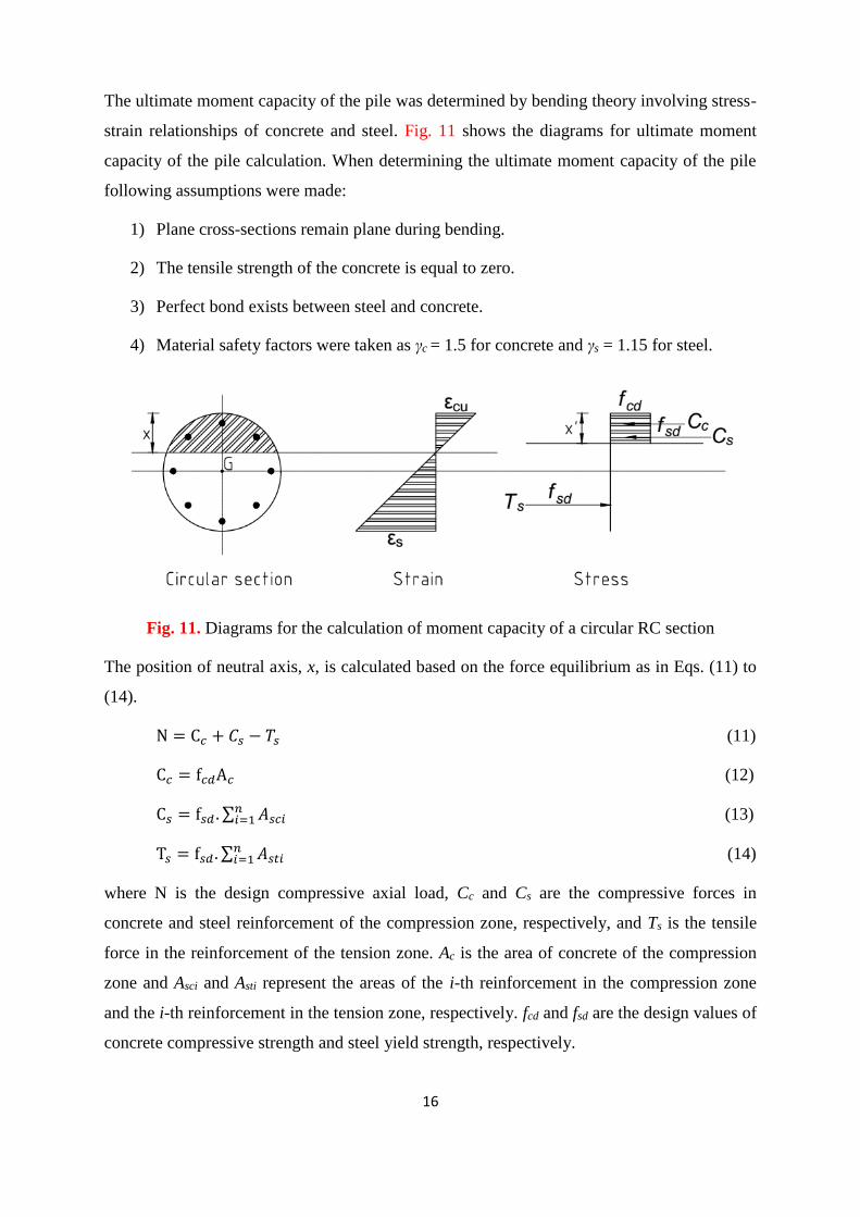
The ultimate moment capacity of the pile was determined by bending theory involving stress-
strain relationships of concrete and steel. Fig. 11 shows the diagrams for ultimate moment
capacity of the pile calculation. When determining the ultimate moment capacity of the pile
following assumptions were made:
1) Plane cross-sections remain plane during bending.
2) The tensile strength of the concrete is equal to zero.
3) Perfect bond exists between steel and concrete.
4) Material safety factors were taken as γc = 1.5 for concrete and γs = 1.15 for steel.
Fig. 11. Diagrams for the calculation of moment capacity of a circular RC section
The position of neutral axis, x, is calculated based on the force equilibrium as in Eqs. (11) to
(14).
N = C𝑐 + 𝐶𝑠 − 𝑇𝑠 (11)
C𝑐 = f𝑐𝑑A𝑐 (12)
C𝑠 = f𝑠𝑑 . ∑ 𝐴𝑠𝑐𝑖𝑛𝑖=1 (13)
T𝑠 = f𝑠𝑑 . ∑ 𝐴𝑠𝑡𝑖𝑛𝑖=1 (14)
where N is the design compressive axial load, Cc and Cs are the compressive forces in
concrete and steel reinforcement of the compression zone, respectively, and Ts is the tensile
force in the reinforcement of the tension zone. Ac is the area of concrete of the compression
zone and Asci and Asti represent the areas of the i-th reinforcement in the compression zone
and the i-th reinforcement in the tension zone, respectively. fcd and fsd are the design values of
concrete compressive strength and steel yield strength, respectively.

17
The determination of location of the neutral axis was carried out by iteration method. Then,
the design moment capacity of the pile, Mult, was calculated as in Eq. (15) and it was
calculated as approximately 206kNm. From the field test results, the calculated maximum
bending moment on the pile is about 29kNm. Since the maximum bending moment on the
pile is less than the moment capacity of the pile, the pile is safe under the above blast tests.
However, it should be noted that the pile ends moments are not measured in this test.
M𝑢𝑙𝑡 = f𝑠𝑑 . ∑ 𝐴𝑠𝑖 . 𝑑𝑠𝑖 + f𝑐𝑑Ac𝑑𝑛𝑖=1 (15)
where Asi is the area of the i-th reinforcement. dsi is the distance to centre of the i-th
reinforcement from centroid of the section and d is the distance to the resultant of the
compression stress in concrete from the centroid of the section.
5. Conclusions
This paper summarised the field test results from a series of blasting tests conducted in
Singapore at a site with residual soil overlying granitic rock. In the field tests, 3 piles of
600mm in diameter were used and all the piles were instrumented with electrical resisting
foil-type strain gauges. The strain gauges were attached on the piles to measure the bending
moments and axial forces along the pile length. The moment distribution shapes differed in
each test in accordance with the ground vibration intensity. The bending moment and axial
force were maximum at the pile head in most of cases with fixed-head piles. However, the
bending moment was maximum at close to the mid-height of the pile for the free-head pile.
The design axial load capacity and moment capacity of the pile were 969kN and 206kNm,
respectively. The maximum axial force and bending moment of the pile are about 152kN and
29kNm, respectively. Since the maximum axial force and bending moment on the pile are
less than the capacities of the pile, the pile is safe under the considered blast tests.
Acknowledgment
This material is based on research/work supported by the Land and Liveability National
Innovation Challenge under L2 NIC Award No. L2NICCFP1-2013-1.
Any opinions, findings, and conclusions or recommendations expressed in this material are
those of the author(s) and do not necessarily reflect the views of the L2 NIC.
18
Assistance during the field tests given by the staff from JTC Corporation, Chye Joo
Construction Pte Ltd, Asia Tunnelling and Construction Pte Ltd and Singapore Test Services
are gratefully acknowledged.
References
[1] Jayasinghe L.B., Zhou H.Y., Goh A.T.C., Zhao Z.Y., and Gui Y.L., Pile response
subjected to rock blasting induced ground vibration near soil-rock interface, Computers and
Geotechnics, 82 (2017), pp. 1-15.
[2] Dusenberry D.O., Handbook for blast resistant design of buildings, 1st edition, John
Wiley and Sons, 2010, pp. 512.
[3] Liao S., Li W., Fan Y., Sun X., and Shi Z., Model test on lateral loading performance of
secant pile walls, Journal of Performance Constructed Facilities, 28(2) (2014), pp. 391–401.
[4] Abdoun T., Dobry R., and O’Rourke T.D., Centrifuge and numerical modeling of soil-pile
interaction during earthquake induced soil liquefaction and lateral spreading, Observation and
modeling in numerical analysis and model tests in dynamic soil-structure interaction
problems, GSP Geotechnical Special Publication No. 64, ASCE, 1997, pp. 76–90.
[5] Wilson D.W., Boulanger R.W., and Kutter B.L., Observed seismic lateral resistance of
liquefying sand, Journal of Geotechnical and Geoenvironment Engineering, 126(10) (2000),
pp. 898–906.
[6] Shim H-S., Response of piles in saturated soil under blast loading, Doctoral thesis,
University of Colorado, Boulder, US, 1996.
[7] Kamijo N., Saito H., Kusama K., Kontani O., and Nigbor R., Seismic tests of a pile-
supported structure in liquefiable sand using large-scale blast excitation, Nuclear Engineering
and Design, 228 (2004), pp 367-376.
[8] Ashford S.A., Juirnarongrit T., Sugano T., and Hamada M., Soil-pile response to blast-
induced lateral spreading. I: Field test, Journal of Geotechnical and Geoenvironmental
Engineering, ASCE, 132(2) (2006), pp 152-162.
[9] Durante M.G., Di Sarno L., Mylonakis G., Taylor C.A., and Simonelli A.L., Soil-pile-
structure interaction: experimental outcomes fromshaking table tests, Earthquake Engineering
and Structural Dynamics, 45(7) (2016), pp. 1041-1061.

19
[10] Nikolaou S., Mylonakis G., Gazetas G., and Tazoh T., Kinematic pile bending during
earthquakes: analysis and field measurements, Geotechnique, 51(5) (2001), pp. 425-440.
[11] Padron L.A., Aznarez J.J., and Maero O., Dynamic analysis of piled foundations in
stratified soils by a BEM-FEM model, Soil Dynamics and Earth quake Engineering, 5 (2008),
pp. 333-346.
[12] Dezi F., Carbonari S., and Leoni G., A model for the 3D kinematic interaction analysis
of pile groups in layered soils, Earthquake Engineering and Structural Dynamics, 38 (2009),
pp. 1281-1305.
[13] Trochanis A, Bielak J, and Christiano P., Three dimensional nonlinear study of piles.
Journal of Geotechnical Engineering (ASCE), 117(3) (1991), pp. 429-447.
[14] Wu G., and Finn W., Dynamic elastic analysis of pile foundations using finite element
method in the time domain, Canadian Geotechnical Journal, 34(1) (1997), pp. 44-52.
[15] Maheshwai B.K., Truman K.Z., EI Naggar M.H., and Gould P.L., Three Dimensional
Finite Element Nonlinear Dynamic Analysis of Pile Groups for Lateral Transient and Seismic
Excitations, Canadian Geotechnical Journal, 41 (2004), pp. 118-133.
[16] Liyanapathirana D.S., and Poulos, H.G., Seismic Lateral Response of Piles in
Liquefying Soil, Journal of Geotechnical and Geo-environmental Engineering, 131(2) (2005),
pp. 1466-1479.
[17] Martinelli M., Burghignoli A., and Callisto L., Dynamic response of a pile embedded
into a layered soil, Soil Dynamics and Earthquake Engineering, 87 (2016), pp. 16-28.
[18] Hao H., Pan T.C., and Zhao Z., Inelastic responses of pile-soil system to blast loads,
WIT Transactions on the Built Environment, 8 (1994).
[19] Huang B., Gao Q., Wang J., Jiang X., Wang X., Jiang B., and Wu W., Dynamic analysis
of pile-soil-structure interaction system under blasting load, Applied Mechanics and
Materials, 638-640 (2014), pp 433-436.
[20] Jayasinghe, L.B., Thambiratnam, D.P., Perera, N., and Jayasooriya, J.H.A.R., Blast
response of reinforced concrete pile using fully coupled computer simulation techniques,
Computers and Structures, 135 (2014), pp. 40-49.
20
[21] Jayasinghe L.B., Thambiratnam D.P., Perera N., and Jayasooriya J.H.A.R., Blast
response and failure analysis of pile foundations subjected to surface explosions, Engineering
Failure Analysis, 39 (2014), pp 41-54.
[22] Chang M.F., and Broms B.B., Design of bored piles in residual soils based on field
performance data, Canadian Geotechnical Journal, 28(2) (1991), pp. 200-209.
[23] Zhao J., Broms B.B., Zhou Y., and Choa V. (1994), A study of the weathering of the
Bukit Timah granite, parts A and B. Bulletin of the International Association of Engineering
Geology 49, pp. 97-105; 50, pp. 105-111.
[24] Sharma J.S., Chu J., and Zhao J. (1999), Geological and Geotechnical Features of
Singapore: an Overview, Tunnelling and Underground Space Technology, 14(4), pp. 419-
431.
[25] Hijikata K., Ishida T., Tanaka H., Koyamada K., Miyamota Y., Kontani O., and Nigbor
R., Experimental study on soil-pile-structure interaction in liquefiable sand subjected to blast-
induced ground motion, 13th World Conference on Earthquake Engineering, Canada, August
2004.
[26] BS 8004, British standard: Code of practice for foundations, 1986.
[27] SS CP4, Singapore standard: Code of practice for foundations, 2003.