a division of tsi intelliag iso6 planter drill control
TRANSCRIPT

INTELLIAG® ISO6™
PLANTER DRILL CONTROLVERSION 4
Operator’s M
anual U
ser Level 2/3
A D I V I S I O N O F T S I ®
®

OPERATOR’S MANUAL
ISO6 Version 4 UL 2_3 Manual / I
6011258 Rev C
Safety Notices ................................................................................................................ 1 Disclaimer .................................................................................................................................. 1
System Components ..................................................................................................... 2 Universal Terminal (UT) ............................................................................................................ 3 ISO6 Master Module .................................................................................................................. 3 Working Set Member (WSMB) Module (Optional) .................................................................... 4 Working Set Member2 (WSMB2) Module (Optional) ................................................................ 4 CAN Terminators ....................................................................................................................... 5
Component Installation ................................................................................................. 6 ISO6 Module .............................................................................................................................. 6 Working Set Member (WSMB) Module ..................................................................................... 7 WSMB Install Considerations .................................................................................................... 7 Bolt WSMB To Frame ................................................................................................................ 8 TIE-Strap WSMB To Frame ...................................................................................................... 8 Connect Cab/Terminal Harnessing ......................................................................................... 11 Connect Implement Harnessing .............................................................................................. 11 Cab Harnessing (Non ISO Bus Ready Tractors) ..................................................................... 12 Implement Harnessing Diagrams ............................................................................................ 13 Accessory Harness (Optional) ................................................................................................. 15 Sensor Installation ................................................................................................................... 15
System Modes ............................................................................................................. 19 Intelliag ISO6 Access ............................................................................................................... 19 Work Mode .............................................................................................................................. 19
User Levels .................................................................................................................. 20 User Level 1 Operator (Basic Access) .................................................................................... 20 User Level 2 (Dealer) .............................................................................................................. 21 User Level 3 (OEM) ................................................................................................................. 23
Navigation And Action Buttons .................................................................................. 24 Navigation ................................................................................................................................ 24 Navigation Buttons Defined ..................................................................................................... 24 Action Buttons.......................................................................................................................... 25 Action Buttons Defined ............................................................................................................ 25
Home Menu .................................................................................................................. 27 Version Information ................................................................................................................. 27 Basic Setup Steps ................................................................................................................... 27 System Setup Buttons ............................................................................................................. 29 System Setup Buttons Defined................................................................................................ 30
Modules ........................................................................................................................ 34 Module Limits:.......................................................................................................................... 34 Connecting Seed Sensors To ISO6 /WSMB ............................................................................ 34 Replacing Installed Modules (Auto Config) ............................................................................. 34 Adding New Modules ............................................................................................................... 36 Auto Sort Feature .................................................................................................................... 36
Identify Harness .......................................................................................................... 37 Selecting A Harness: ............................................................................................................... 37

OPERATOR’S MANUAL
II / ISO6 Version 4 UL 2_3 Manual
6011258 Rev C
Row Setup .................................................................................................................... 38 Configuration Setup ................................................................................................................. 39
Material Setup .............................................................................................................. 39 Creating A Materials Table ...................................................................................................... 41 Clear Material From Table ....................................................................................................... 42 View Next Material Page ......................................................................................................... 43 Edit/Define Material Parameters.............................................................................................. 43 Material Type ........................................................................................................................... 44 Planter Control Material Type .................................................................................................. 46 High/Low Population Alarms ................................................................................................... 49 Granular Seeding Material Type.............................................................................................. 50 Liquid Flow Material Type ........................................................................................................ 56 Planter Monitor Material Type ................................................................................................. 59 Granular Monitor Material Type ............................................................................................... 63 Shaft Control ............................................................................................................................ 66 Fan Control .............................................................................................................................. 69
Control Channel Setup ................................................................................................ 71 Assign A Control Channel ....................................................................................................... 71 Delete A Control Channel ........................................................................................................ 72 Copy A Control Channel .......................................................................................................... 73 Channel Linking ....................................................................................................................... 73 Control Channel Type .............................................................................................................. 74 Planter Control Channel .......................................................................................................... 75 Granular Control Channel ........................................................................................................ 77 Liquid Flow Control Channel ................................................................................................... 80 Nozzles .................................................................................................................................... 82
Planter Monitor Channel ............................................................................................. 84 Granular Monitor Channel ....................................................................................................... 86 Fan Control .............................................................................................................................. 88 Disable Control On Control Failure Alarm ............................................................................... 90 Shaft Control ............................................................................................................................ 90 Individual Row Control (IRC) ................................................................................................... 92 Drop Spreader ......................................................................................................................... 93
Calibrations-Valve And Spreader ............................................................................... 94 Planter Control And Granular Valve Calibration ...................................................................... 94 Perform A Valve Calibration .................................................................................................... 94 Limit Output (Granular) ............................................................................................................ 95 Spreader Calibration (Granular) .............................................................................................. 97 Spreader Constants Defined ................................................................................................... 98 Liquid Flow Calibration ............................................................................................................ 99 Limit Output ........................................................................................................................... 101 K-Factor Calibration ............................................................................................................... 101 Perform A Liquid Flow Catch Test ......................................................................................... 102
Operations ................................................................................................................. 103 To Edit An Operation: ............................................................................................................ 103
Section Control .......................................................................................................... 104 Clutch Sections ...................................................................................................................... 104 Identify Sections And Outputs ............................................................................................... 104 Assign Channels/Rows/Outputs/Switches ............................................................................ 105

OPERATOR’S MANUAL
ISO6 Version 4 UL 2_3 Manual / III
6011258 Rev C
Liquid Boom Section Control ................................................................................... 107 Boom Setup ........................................................................................................................... 107 Assign Channels, Rows, Outputs, Switches ......................................................................... 108
Section Linking .......................................................................................................... 109
Section Linking Examples ........................................................................................ 111 Implement Geometry ............................................................................................................. 112 Three-Point Hitch Type .......................................................................................................... 114 Semi-Mount And Drawbar Hitch Types ................................................................................. 115 Double Pivot Hitch Type ........................................................................................................ 116
Sensor Setup ............................................................................................................. 118 Sensor Configuration Requirements: .................................................................................... 118 Sensor Setup ......................................................................................................................... 119 Sensor Summary ................................................................................................................... 121 Sensor Details ....................................................................................................................... 122 Module And Sensor Setup Comparison ................................................................................ 124 Ground Speed Setup ............................................................................................................. 126
Accessory Sensors ................................................................................................... 131 Accessory Summary .............................................................................................................. 131 Accessory Setup .................................................................................................................... 131 Accessory Alarm Setup ......................................................................................................... 133 Pressure Sensor Setup ......................................................................................................... 134 Hopper Sensor Setup ............................................................................................................ 135 Rpm Sensor Setup ................................................................................................................ 136 Digital Sensor Setup .............................................................................................................. 137
Bout Markers ............................................................................................................. 139 Bout Marker Setup ................................................................................................................. 139
Customizing The Work Screen ................................................................................. 141 Modifying The Instrument Layout .......................................................................................... 142 Selecting An Instrument ........................................................................................................ 143 Instruments Without Setup Defined ....................................................................................... 145 Instruments With Setup Defined ............................................................................................ 145 Area Instrument ..................................................................................................................... 151 Materials Instrument .............................................................................................................. 154 Product Levels ....................................................................................................................... 156 Accessories ........................................................................................................................... 157
Operation ................................................................................................................... 159 Performing A Fill Disk ............................................................................................................ 159 Begin Operation ..................................................................................................................... 160 Scroll Work Mode Screens .................................................................................................... 161 Work Screen Functions ......................................................................................................... 162 Reading The Control Instrument ........................................................................................... 162 Control Channel Adjustment .................................................................................................. 163 Operate Screen Symbols ...................................................................................................... 164 Task Controller Icon .............................................................................................................. 165 Work Mode Information Screens ........................................................................................... 165 Control Channel ..................................................................................................................... 166 Materials ................................................................................................................................ 167 Seed Count ............................................................................................................................ 167 Population .............................................................................................................................. 168

OPERATOR’S MANUAL
IV / ISO6 Version 4 UL 2_3 Manual
6011258 Rev C
Product Levels ........................................................................................................... 174 Using The Precharge Feature ............................................................................................... 176 Dispensing Material With Flush Enable ................................................................................. 177 Manual Speed Mode ............................................................................................................. 178 Task Controller Compatibility ................................................................................................. 179 Selecting A Universal Terminal Type .................................................................................... 180 Override Tc Functionality ....................................................................................................... 181
Import/Export Data .................................................................................................... 182
System Test ............................................................................................................... 184 Continuous Test .................................................................................................................... 184 5 Rev Test ............................................................................................................................. 185 Remote Test Switch .............................................................................................................. 186
Accumulators ............................................................................................................ 188 Seed Count ............................................................................................................................ 188 Totals ..................................................................................................................................... 188
Version Information ................................................................................................... 191 To View Version Information: ................................................................................................ 191
Factory Reset (User Level 3) .................................................................................... 193
Alarms ........................................................................................................................ 194 Alarm Log And Details ........................................................................................................... 194 Alarm Reset (Level 3 OEM User) .......................................................................................... 195
Diagnostics ................................................................................................................ 196 Manual Open Of Channel (System Failure) .......................................................................... 198
Software Add-Ons ..................................................................................................... 201 To View Feature Keys: .......................................................................................................... 201 Feature Key Possible Add-Ons ............................................................................................. 201
Troubleshooting & Alarm Codes .............................................................................. 202

OPERATOR’S MANUAL
ISO6 Version 4 UL 2_3 Manual SAFETY NOTICES / 1
6011258 Rev C
SAFETY NOTICES
Safety notices are one of the primary ways to call attention to
potential hazards.
This Safety Alert Symbol identifies important safety messages
in this manual. When you see this symbol, carefully read the
message that follows. Be alert to the possibility of personal
injury or death.
WARNING
Use of the word WARNING indicates a potentially hazardous
situation which, if not avoided, could result in death or
serious injury.
CAUTION
Use of the word CAUTION with the Safety Alert Symbol
indicates a potentially hazardous situation which, if not
avoided, may result in minor or moderate injury.
CAUTION
Use of the word CAUTION without the Safety Alert Symbol
indicates a potentially hazardous situation which, if not
avoided, may result in equipment damage.
DISCLAIMER
DICKEY-john reserves the right to make engineering refinements
or procedural changes that may not be reflected in this manual.
Material included in this manual is for informational purposes and
is subject to change without notice.

OPERATOR’S MANUAL
2 / SYSTEM COMPONENTS ISO6 Version 4 UL 2_3 Manual
6011258 Rev C
SYSTEM COMPONENTS
The DICKEY-john IntelliAg ISO6 is a complete monitoring and
control system that provides up to 8 channels of control for row
crop planters, drills, air seeders, and air carts to control planting,
liquid, and granular applications. The system monitors up to
120 rows with up to 6 sensors per row for individual row
performance and population. 1 ground speed, 5 hopper levels,
4 air pressure, 4 RPM sensor, and 1 lift switch are available with
additional working set members (WSMB).
NOTE
The IntelliAg system is designed to ISO11783 CAN
communication standards providing the capability
of communicating with other manufacturer’s
ISO11783-compatible equipment.
The IntelliAg system includes the following
required components:
Universal Terminal
ISO6 Master Module
Safety Input Sensors (any two of the following)
- Implement Lift
- Ground Speed
- Secondary Ground Speed
Master Switch
Two CAN Terminators
Cab and Implement Harnessing
Optional components include:
Working Set Member Modules (WSMB)
Implement Lift
ISO Output Module (section control)
Working Set Member 2 (seed singulation)
Remote Test Switch (required for Continuous Test
and 5 Rev Test)
WSMB Accessory Module
Frame Fold Module
Row Shutoff Switch Module
Boom Shutoff Switch Module
Tramline Module
DICKEY-john provides a full suite of complimentary sensors that
are compatible with the IntelliAg ISO6 platform.
Terminal mounts in the cab using:
RAM Mount
Terminal Mounting Plate
OPERATOR’S MANUAL
ISO6 Version 4 UL 2_3 Manual SYSTEM COMPONENTS / 3
6011258 Rev C
UNIVERSAL TERMINAL (UT)
A universal terminal is the main user interface with the IntelliAg
system components to monitor and control product application.
ISO6 is compatible with most ISO11783-compliant universal
terminals.
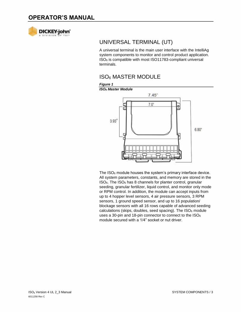
ISO6 MASTER MODULE
Figure 1
ISO6 Master Module
The ISO6 module houses the system’s primary interface device.
All system parameters, constants, and memory are stored in the
ISO6. The ISO6 has 8 channels for planter control, granular
seeding, granular fertilizer, liquid control, and monitor only mode
or RPM control. In addition, the module can accept inputs from
up to 4 hopper level sensors, 4 air pressure sensors, 3 RPM
sensors, 1 ground speed sensor, and up to 16 population/
blockage sensors with all 16 rows capable of advanced seeding
calculations (skips, doubles, seed spacing). The ISO6 module
uses a 30-pin and 18-pin connector to connect to the ISO6
module secured with a 1/4” socket or nut driver.

OPERATOR’S MANUAL
4 / SYSTEM COMPONENTS ISO6 Version 4 UL 2_3 Manual
6011258 Rev C
WORKING SET MEMBER (WSMB) MODULE (OPTIONAL)
Each Working Set Member (WSMB) module is an auxiliary to the
ISO6. A WSMB can accept up to 18 rows of seed sensors. The
WSMB passes information directly to the ISO6. Up to 8 WSMB’s
can be installed to monitor up to 120 sensors. The flexible design
of the WSMB allows for installation virtually anywhere on the
implement.
Figure 2
Working Set Member Module
WORKING SET MEMBER2 (WSMB2) MODULE (OPTIONAL)
Figure 3
Working Set Member 2 Module

OPERATOR’S MANUAL
ISO6 Version 4 UL 2_3 Manual SYSTEM COMPONENTS / 5
6011258 Rev C
A Working Set Member 2 module provides seed singulation
calculations for spacing quality, seed singulation, skips, and
multiples. A maximum of 5 WSMB2 modules can be installed to
monitor up to 90 sensors. A total of 96 sensors are supported for
seed quality data using a combination of WSMB2 modules and
the ISO6 Master Module.
CAN TERMINATORS
CAN terminators are necessary for proper communication
between each component of the system.
One terminator is located on the cab harness approximately
30 inches from the universal.
One terminator plugs into the implement harness of the last
module connected to the CAN bus.
Figure 4
CAN Terminator
OPERATOR’S MANUAL
6 / COMPONENT INSTALLATION ISO6 Version 4 UL 2_3 Manual
6011258 Rev C
COMPONENT INSTALLATION
ISO6 MODULE
1. Select an area on the implement to mount the ISO6 module
that allows for easy hookup and access.
2. Use the enclosure as a template to mark the location of the
mounting holes.
3. Drill four 9/32 inch diameter holes where marked.
4. Mount with the label side of module facing out. Do not mount
with the connector facing up (see Caution).
IMPORTANT
Do not use the enclosure as a guide when drilling. Do not over
tighten nuts as this may damage the mounting tabs of the
enclosure. Recommended torque is 10-12 in-lbs.
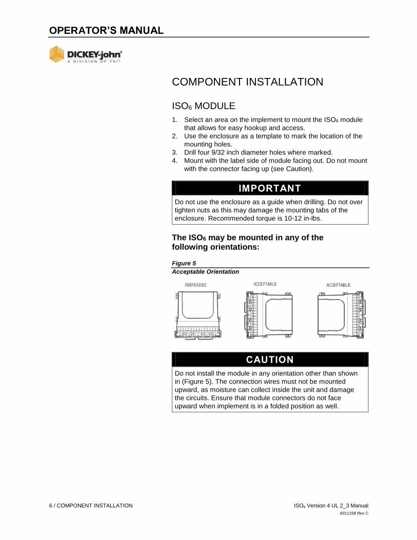
The ISO6 may be mounted in any of the following orientations: Figure 5
Acceptable Orientation
CAUTION
Do not install the module in any orientation other than shown
in (Figure 5). The connection wires must not be mounted
upward, as moisture can collect inside the unit and damage
the circuits. Ensure that module connectors do not face
upward when implement is in a folded position as well.

OPERATOR’S MANUAL
ISO6 Version 4 UL 2_3 Manual COMPONENT INSTALLATION / 7
6011258 Rev C
WORKING SET MEMBER (WSMB) MODULE
The WSMB module can be attached to the implement by:
1. Bolting to the implement.
2. Using tie straps to secure to implement.
IMPORTANT
For applications using multiple modules, it is
recommended that the WSMB’s are mounted on the
implement by increasing serial number order from
left to right.
Figure 6
WSMB
WSMB INSTALL CONSIDERATIONS
1. Select an area on the implement to mount the member that
allows for easy hookup and access. Extensions may be
used to reach members installed on remote areas of
the implement.
2. The module can be mounted in the same orientations as the
ISO6 module as illustrated in (Figure 5).
3. Mount with the label side of the module facing out.
CAUTION
Do not install the module in any orientation other than
illustrated in (Figure 5). The connection wires must not be
mounted upward as moisture can collect inside the unit
and damage the circuits. Ensure that module connectors
do not face upward when implement is in a folded
position as well.

OPERATOR’S MANUAL
8 / COMPONENT INSTALLATION ISO6 Version 4 UL 2_3 Manual
6011258 Rev C
BOLT WSMB TO FRAME
1. Use the enclosure as a template to mark the location of the
mounting holes.
2. Drill two 9/32 inch diameter holes where marked.
3. Attach to frame using 1/4 x 20 bolts or other fastening
devices as illustrated in (Figure 7).
CAUTION
Do not use the enclosure as a guide when drilling. Do not
over tighten nuts as this may damage the mounting tabs
on the enclosure.
Figure 7
Working Set Member Installation (Bolted)
TIE-STRAP WSMB TO FRAME
1. Use one long tie-strap to loop around the member body and
through both mounting holes as illustrated in (Figure 8).
2. If necessary, drill mounting holes described above.

OPERATOR’S MANUAL
ISO6 Version 4 UL 2_3 Manual COMPONENT INSTALLATION / 9
6011258 Rev C
3. Securely tighten tie-strap.
4. Install a second tie-strap toward the label end of the
enclosure for additional support.
Figure 8
Working Set Member Installation (Tie-Strap)
5. Connect a WSMB harness to the WSMB module and
connect the WSMB harness to the Power/CAN backbone,
refer to (Figure 11).
6. Connect each module harness to its module inserting both
connectors until the connector locking tabs engage.
7. Layout the planter harness along the implement frame to
each of the seed sensors.
- For seed sensors, extensions will most likely not be
necessary.
8. Route sensor wires in locations where they will not be
damaged by chains, drive shafts, sprockets, etc.
9. Secure the harness to the toolbar with a minimum of 3”
straight wire exiting the module before bending and
attaching with tie-straps.
10. Coil and secure any unused sensor connections.
11. The WSMB Module harness can accept a standard
DICKEY-john PM style planter harness (single round 37-pin
connector) or an SE style planter harness (1 gray 12-pin,
1 black 12-pin rectangular connector) depending on the
WSMB harness. Harnesses are available for a number of
row configurations.
- Route the planter harness on the implement, securing
as necessary.
- Install seed sensors per the instructions included with
the sensors. Refer to the implement harness diagram for
additional information (Figure 11) or (Figure 12).

OPERATOR’S MANUAL
10 / COMPONENT INSTALLATION ISO6 Version 4 UL 2_3 Manual
6011258 Rev C
IMPORTANT
Be sure the locking tabs engage when inserting the
connectors. The connection is sealed only when the
locking tabs have fully engaged.
NOTE
The last module harness in the system must have a CAN
Terminator installed for proper system operation. Refer to
Implement Harness (Figure 10) or (Figure 11) for additional
information.
12. Connect any additional adapter harnesses to the module
harness. The ISO6 T-Harness can accept the following
adapter harnesses:
- Channel Actuator Harness: This harness has 2 PWM
Outputs, 2 Channel Feedbacks, 1 RPM Sensor,
1 Hopper Sensor, 1 Speed Sensor, 1 Implement Lift
Switch, and 1 Test Switch (P/N 467980162).
- Channel Actuator Harness: This harness accepts up to
4 Output Control Channels, 4 Control Channel
Feedbacks, 1 Hopper Level Sensor Input, 1 Shaft
Sensor Input, 1 Ground Speed Input, 1 Implement
Switch Input, and a Test Switch Connector
(P/N 467980160, 467980164). In addition, a pair of 6-pin
connectors are available for Servo connection that use
FB1/FB2 respectively. Install sensors, valves, etc. per
the instructions included with the items. Install the PWM
valve assembly and feedback sensor for each control
loop and connect the devices to their respective inputs
on the harness, making certain to match PWM1/Servo 1
with FB1, PWM2/Servo 2 with FB2 etc. Secure any
unused and excess cable lengths where necessary.
- 6 Channel Actuator Harness: Similar to the 4 Channel
Actuator Harness but brings in a second speed input and
adds feedback 5 and 6. Servos are labeled 5 and 6 and
must be matched with feedback 5 and 6.
- 8 Channel Actuator Harness: Similar to the 6 Channel
Harness buts replaces the 2 servo channel outputs with
4 more PWM channel outputs. PWM outputs are labeled
1-8 and must be matched with the respective 1-8
feedback.
- 4 Channel Servo Harness: Similar to the 6 Channel
Actuator Harness but replaces the 4 PWM channel
outputs with 2 servo outputs. Servos are labeled 1
through 4 and must be matched with their respective 1
through 4 feedbacks.

OPERATOR’S MANUAL
ISO6 Version 4 UL 2_3 Manual COMPONENT INSTALLATION / 11
6011258 Rev C
- Seed Sensor Harness: This harness accommodates
any standard Dj Seed Sensor Harness (PM style 16 row
or SE style 12 row) depending on the ISO6 harness.
Install all seed sensors per the instructions included with
the individual sensors.
A wide variety of harnesses are available to accommodate
various numbers of sensor inputs. Secure any unused or excess
cable lengths as necessary.
CONNECT CAB/TERMINAL HARNESSING
Refer to (Figure 9). (FOR NON-ISOBUS READY TRACTORS)
1. Connect the cab harness to the back of the
universal terminal.
2. Connect the power leads directly to the battery.
3. Connect the ignition wire to a switched +12VDC.
4. Connect the ground leads to the negative battery
terminal post.
5. Connect the CAN terminator, radar speed sensor, and row
switch module (optional) to the respective connectors on the
cab harness.
TIP: If the speed sensor is connected to the IntelliAg
actuator/control harness, do not connect anything to the speed
sensor connector on the cab harness. Route the IBBC connector
to the rear of the tractor where implement attachment occurs.
Mount IBBC connector in a secure location at the rear of
the tractor.
CONNECT IMPLEMENT HARNESSING
Refer to (Figure 10) and (Figure 11).
1. Connect the Implement CAN Breakaway extension to the
mating IBBC connector installed on the back of the tractor.
If using an ISO-ready tractor and terminal, the
implement connect can be plugged directly into the
OEM IBBC connector.
2. Route the harness along the implement hitch to the ISO6
module harness (use an implement extension harness if
additional length is needed).
3. Secure harness as needed.
4. Connect the module harness to the mating connectors of the
Implement CAN harness and then connect the module to the
harness. The ISO6 harness module uses a 30 and 18-way
connector with a jackscrew to secure the connector to the
module using a 1/4” socket or nut driver. The WSMB uses a
pair of 12-pin connectors.
5. Secure module harness as needed.

OPERATOR’S MANUAL
12 / COMPONENT INSTALLATION ISO6 Version 4 UL 2_3 Manual
6011258 Rev C
CAB HARNESSING (NON ISOBUS READY TRACTORS)
The UT display connects to the tractor cab harness via an
adapter harness. A GPS receiver is required to provide
implement position via CAN or RS232 communication. A row
switch module provides quick access of turning sections on and
off when manual override is required. Ignition wire connects to
switched power source.
A DICKEY-john output module and harness are required for
interfacing with shutoff modules (Tru Count solenoid modules
are not supplied by DICKEY-john). Harnessing structure
illustrated below. Figure 9
Cab Harness Connections to Universal Terminal

OPERATOR’S MANUAL
ISO6 Version 4 UL 2_3 Manual COMPONENT INSTALLATION / 13
6011258 Rev C
IMPLEMENT HARNESSING DIAGRAMS
Various implement harness options are available based on
application type and must be selected at the System screen.
Figure 10
Implement Harnessing
ISO6 Master Module

OPERATOR’S MANUAL
14 / COMPONENT INSTALLATION ISO6 Version 4 UL 2_3 Manual
6011258 Rev C
Figure 11
Implement Harnessing

OPERATOR’S MANUAL
ISO6 Version 4 UL 2_3 Manual COMPONENT INSTALLATION / 15
6011258 Rev C
ACCESSORY HARNESS (OPTIONAL)
Figure 12
Accessory Harness
SENSOR INSTALLATION
For proper system operation, all sensors used with the system
must be connected properly as described in the following
sections. Sensors that are incorrectly installed will not be
properly identified by the system and will result in incorrect
numbering of the sensors.
SEED SENSORS
The system is compatible with all existing DICKEY-john seed
sensors. Seed sensors may be connected to the ISO6 master
module and all WSMB planter monitor modules. Any number of
sensors up to the maximum capacity of the module may be
connected with up to 6 sensors per row. A maximum of 196 seed
sensors can be connected to the system.

OPERATOR’S MANUAL
16 / COMPONENT INSTALLATION ISO6 Version 4 UL 2_3 Manual
6011258 Rev C
When connecting seed sensors to the modules, the following
requirements must be observed:
All seed sensors installed must be connected to the seed
sensor harness SEQUENTIALLY starting with the Row 1
input. In the event that not all row inputs on the module are
used, the unused inputs must be the last inputs on that
module.
If the module has multiple sensors for the same row, all
sensors assigned to the same channel must be sequential.
Figure 13
Correct Seed Sensor Module Connection

OPERATOR’S MANUAL
ISO6 Version 4 UL 2_3 Manual COMPONENT INSTALLATION / 17
6011258 Rev C
Figure 14
Incorrect Seed Sensor Module Connection
Failure to correctly install seed sensors will result in incorrect row
assignment on the planter monitor display functions and alarms.
HOPPER LEVEL SENSORS
The system is compatible with the DICKEY-john planter hopper
level sensors. One hopper level sensor can connect to the
actuator harness and another 4 hopper sensors connect using
an accessory harness (P/N 46798-0201). Both harnesses are
connected to the ISO6. The hopper level connection is labeled
HOPPER 1 2.
RPM SENSORS
The system is compatible with all existing DICKEY-john digital
RPM sensors. One RPM sensor connects to the ISO6 module.
The sensor connects to the actuator harness and is labeled
RPM 1. Up to 3 additional RPM sensors connect to an accessory
harness (P/N 46798-0201).

OPERATOR’S MANUAL
18 / COMPONENT INSTALLATION ISO6 Version 4 UL 2_3 Manual
6011258 Rev C
AIR PRESSURE SENSORS
The system is compatible with DICKEY-john air pressure
sensors. One air pressure sensor with adapter harness connects
to the RPM harness connection labeled RPM1. Three
additional pressure sensors connect to accessory harness
(P/N 46798-0201). Other frequency based air pressure sensors
may be used and configured in the sensor setup menu.

OPERATOR’S MANUAL
ISO6 Version 4 UL 2_3 Manual COMPONENT INSTALLATION / 19
6011258 Rev C
SYSTEM MODES
INTELLIAG ISO6 ACCESS
The IntelliAg system is accessed by pressing the ISO6 button
located in the UT’s working set list.
The ISO6 Control System has two modes of operation:
Work Mode (master/control switch ON or implement
DOWN).
System Setup (Level 2 and 3 users are accessible
with password).
WORK MODE
When the master/control switch is in the ON position, the START
button is pressed with the implement down, ground speed is
greater than 0, or the minimum ground speed is shutoff; the
ISO6 Control System is in Work Mode. In this mode, all enabled
system components and control channels are operational, as
well as all monitoring functions and system accumulators.
When the master switch is in the OFF position or the STOP
button is pressed (red), the implement up, or ground speed is 0
or less than the defined ground speed shutoff, all control and row
monitoring functions cease.
Figure 15
IntelliAg ISO6 Icon and Work Mode Active
OPERATOR’S MANUAL
20 / USER LEVELS ISO6 Version 4 UL 2_3 Manual
6011258 Rev C
USER LEVELS
The system has three user levels that allow access to certain
screens based on user level type.
User Level 1 Operator (Basic View)
User Level 2 Dealer (Advanced Setup)
User Level 3 OEM (Authorized Personnel)
At initial power up the system will being in user level 3 (OEM).
After a power cycle, the system will continue to log into the
chosen User level until changed at the Password screen. The
user level is changed at the Version screen using a password.
USER LEVEL 1 OPERATOR (BASIC ACCESS)
Operator View (User Level 1) is a restricted level that does not
allow any setup/configuration constants to be changed.
In operator view the following functions can be performed:
Assign materials to channels
Access calibration parameters
Perform a fill disk
Increase and decrease rates
Turn on/off a control channel
Change instruments on Work screen
Access Diagnostics screen
View Version screen
View Alarm Log and Detail screens
View Section Control screen
View Implement Geometry screen
View Speed screen
All Setup screens are viewable in level 1 mode with non-
selectable constants in a gray tone.
TO SET USER LEVEL 1 MODE:
1. Press the VERSION button.
2. At the Version screen, press the PASSWORD button.
3. At the Password screen, press the LEV 1 LOCK button.
4. The “OEM or Dealer Screens On” located at screen bottom
disappears after the LEV 1 LOCK button is pressed as an
indicator it is now in user level 1 mode.

OPERATOR’S MANUAL
ISO6 Version 4 UL 2_3 Manual USER LEVELS / 21
6011258 Rev C
Figure 16
Locking to User Level 1
USER LEVEL 2 (DEALER)
User Level 2 provides open access to all setup/configuration
screens excluding Factory Reset and the Alarm Log. To change
from operator level to dealer level, a 6-digit password is required.
Password includes the five-digit serial number found on the label
of the ISO6 or on the Version screen.
TO UNLOCK TO DEALER ACCESS:
1. At the Version screen:
- Record the serial number of the ISO6 module.
- Press the PASSWORD button.
2. On the Password screen, enter the 6-digit password as
follows:
- Enter the first digit as 2.
- For the next five digits, enter the last five digits of the
serial number taken from the ISO6 module found on the
label or
- the last five digits found at the Version Information
screen (example S/N 163210044 - use 10044).
3. Press the Checkmark button to accept password. At the
Password screen, text at screen bottom states “Dealer
screens on” in the User Level 2 (Dealer) mode.
OPERATOR’S MANUAL
22 / USER LEVELS ISO6 Version 4 UL 2_3 Manual
6011258 Rev C
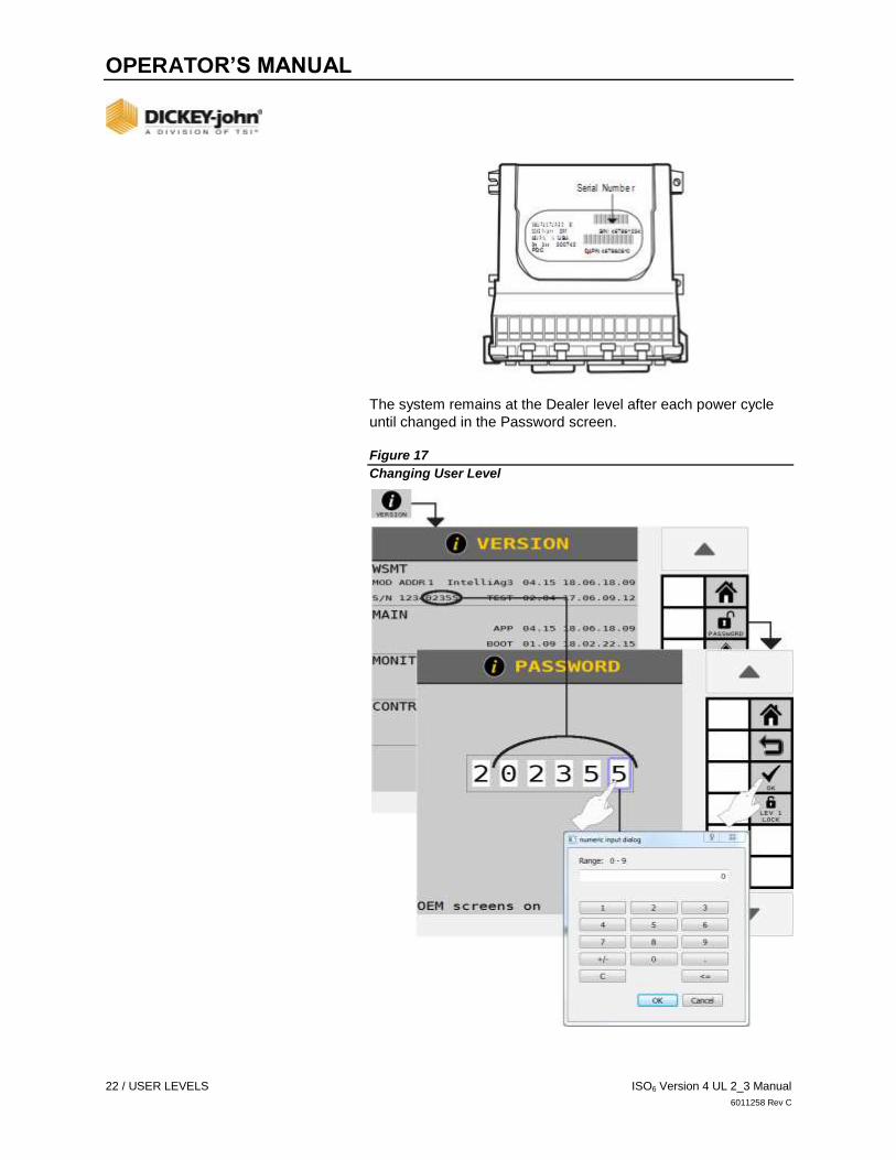
The system remains at the Dealer level after each power cycle
until changed in the Password screen.
Figure 17
Changing User Level

OPERATOR’S MANUAL
ISO6 Version 4 UL 2_3 Manual USER LEVELS / 23
6011258 Rev C
USER LEVEL 3 (OEM)
User Level 3 (OEM) mode provides access to many features not
available to Level 2 (Dealer), including access to three additional
features:
1. SET DEFAULTS button - Allows setting to factory defaults or
to the previous configuration settings.
2. ALARM LOG button - Clearing of Alarm logs.
3. Control Channel and Row-Pro Calibration Parameters
screen - Manual adjustment of valve calibration parameters.
These adjustments should be made with the guidance of a
DICKEY-john technical support representative.
4. MODULE AUTO-SORT button – sorts modules according to
serial number.

OPERATOR’S MANUAL
24 / NAVIGATION AND ACTION BUTTONS ISO6 Version 4 UL 2_3 Manual
6011258 Rev C
NAVIGATION AND ACTION BUTTONS
A set of buttons on the right side of each screen guides the user
to navigate between screens. Some system functions have multi-
tiered setup screens with a unique set of navigation buttons to
guide within those system setup screens. Location of these
buttons are based off of the settings in the Universal Terminal.
Figure 18
Navigation Buttons Defined
NAVIGATION
NAVIGATION BUTTONS DEFINED
HOME
The HOME button is always located as the first button on a
screen and returns to the top level menu when pressed.
LEFT/RIGHT ARROWS
The Left Arrow button returns to the previous screen within the
multi-tiered setup screens. A Right Arrow button indicates there
is an additional setup screen; pressing the right arrow advances
to the next setup screen.
BACK
The Back button returns to the top level screen within a multi-
tiered setup function, i.e., setting up a control channel has
several screens within the setup function. Pressing the Back
button returns to the top level screen within Control setup.

OPERATOR’S MANUAL
ISO6 Version 4 UL 2_3 Manual NAVIGATION AND ACTION BUTTONS / 25
6011258 Rev C
DOWN/UP ARROWS
Used to navigate in the same page or move to the previous/next
set of data.
ACTION BUTTONS
Action buttons perform an action relating to setting up system
parameters. Some system functions have multi-tiered setup
screens with a unique set of navigation buttons to guide within
those system setup screens. These button’s locations are part of
the Virtual Terminal settings and may look slightly different
than shown.
Figure 19
Action Buttons Defined
ACTION BUTTONS DEFINED
MODIFY
The MODIFY button is only available on the top level Home
Menu and is used to select and place a commonly used button
on the top level Home Menu.
EDIT
The EDIT button allows modification of parameters for Materials,
Channels, Channel Linking, Accessories, Operations, Section
Linking setup screens, and other screens.

OPERATOR’S MANUAL
26 / NAVIGATION AND ACTION BUTTONS ISO6 Version 4 UL 2_3 Manual
6011258 Rev C
COPY
Allows material, control channel, or accessory parameters to be
copied and added as another instance of that setup type.
CLEAR
Removes any of: material from the material library, button from
the Main Menu, or an instrument from the instrument library.
NEXT
Used to navigate to the next page or next set of data.
ALARM CANCEL
Cancels an active alarm.
DONE
Accepts changes made to the displayed screen.
ACCEPT
Accepts changes made to the displayed screen.
CANCEL
Cancels changes made to the displayed screen and reverts to
the previous settings.
Additional buttons that are specific to the selected setup screen
are described in the relevant sections throughout the manual.

OPERATOR’S MANUAL
ISO6 Version 4 UL 2_3 Manual HOME MENU / 27
6011258 Rev C
HOME MENU
The default Home Menu is the main screen that a user interfaces
with to gain access to primary system setup screens and the
Work Screen. The Home Menu also allows access to the system
version information and user access levels.
VERSION INFORMATION
Provides software version installed for the ISO6 and connected
modules, allows access to enter user level passwords, and
restart the system.
BASIC SETUP STEPS
The basic steps below are recommended in the listed order for
initial system setup:
1. MODULES configuration (set module addresses)
2. SYSTEM screen (select harness)
3. ROWS (assign)
4. CONTROLS (define control channels)
5. OPERATIONS (define control/application configuration)
6. MATERIALS (specify material type)
7. CLUTCH SECTIONS (setup for section control)
8. LIQUID SECTIONS (setup for liquid section control)
9. GEOMETRY
10. SENSORS (assign sensor type)
11. ACCESSORIES
12. INSTRUMENTS (set up Instruments in Work Screen view)
13. All setup steps are configurable in any order. System setup
buttons at the Home Menu screen are the main setup
parameters for the system operation and are prioritized from
left to right, top to bottom in the recommended setup order
(Figure 20).
Figure 20
Home Menu Screen

OPERATOR’S MANUAL
28 / HOME MENU ISO6 Version 4 UL 2_3 Manual
6011258 Rev C
REPLACE A SYSTEM SETUP BUTTON ON THE HOME MENU:
1. Press the MODIFY button. The Home Menu is now in
EDIT mode.
2. Select the button on the Home Edit screen to replace
with new.
3. Select the desired button to replace the button selected on
the Home Menu.
- Two Button Selection screens display in Edit mode with
available Setup buttons.
- Press the Next Page button to display the second Button
Selection menu.
4. The selected new button auto fills into the selected area at
the Home Menu.
5. When finished, press the DONE button to return to the Home
Menu that now displays the new button.
Figure 21
Customizing the Home Menu
REMOVE A BUTTON FROM THE HOME MENU:
1. Press the MODIFY button.
2. Select the button to clear from the Home Menu.
3. At the Button Selection screen, press the CLEAR button.
4. The button is automatically cleared from the Home Menu
and a blank placeholder button added until a new button
is added.
5. When finished, press the DONE button to return to the Home
Menu that now displays an empty placeholder button.

OPERATOR’S MANUAL
ISO6 Version 4 UL 2_3 Manual HOME MENU / 29
6011258 Rev C
Figure 22
Removing a Button from the Home Menu
SYSTEM SETUP BUTTONS
Dedicated buttons are used to setup the Home Menu and also
provide navigation to setup system functions. Press the Right
Arrow button to display 1 of 2 button selection screens. Buttons
are in alphabetical order.

OPERATOR’S MANUAL
30 / HOME MENU ISO6 Version 4 UL 2_3 Manual
6011258 Rev C
Figure 23
Button Selection Screens.
SYSTEM SETUP BUTTONS DEFINED
WORK SCREEN
Available only on the Home Menu and opens the Work Screen
used during normal operation to monitor and control applications.
ACCESSORIES
Setup parameters for installed sensors, e.g. pressure, hopper,
RPM, digital.
ALARM LOG
A listing of alarms that have occurred to the system with details
on each alarm as well as a Reset button to clear alarms.

OPERATOR’S MANUAL
ISO6 Version 4 UL 2_3 Manual HOME MENU / 31
6011258 Rev C
CLUTCH SECTIONS
Planter Clutch Setup; define sections by channels, rows,
outputs, and switches, to automatically or manually shut off
individual sections.
CONTROLS
Setup of the control channel type identifying the channel
parameters.
DIAGNOSTICS
Informational screen to aid in troubleshooting for system issues.
FACTORY RESET
Clears setup parameters and returns to factory default settings
or overwrites factory defaults to the existing configuration
settings as defined by the user. Alarm Log and Accumulators
will be lost.
FOLD SEQUENCE
Set up Frame Folding steps, working hydraulics, and hardware.
GEOMETRY
Entry of physical implement coordinates in relation to fixed
positions on the vehicle to determine GPS coordinates
in the field.
IMPORT/EXPORT
Implement configurations stored on the ISO6 can be exported to
a USB memory device for transfer to other machines. This file
transfer eliminates manual entry of all settings to similar
machines via the import feature.
IRC SECTIONS
Define Individual Row Control (IRC) sections by channels,
rows, and switches to automatically or manually shut off
individual sections.
IRC SETUP
Setup Individual Row Control (IRC) module hardware.
INSTRUMENTS
Allows customization of the Work Screen to display system
functions and instruments to user preferences.

OPERATOR’S MANUAL
32 / HOME MENU ISO6 Version 4 UL 2_3 Manual
6011258 Rev C
LIQUID SECTIONS
Define sections by channels, rows, outputs, and switches to
automatically or manually shut off individual sections (Liquid).
MARKERS
Enables or disables bout marker outputs and feedback.
MATERIALS
Setup of material types that are assigned to a control channel.
Minimum/maximum limits, target rates, and alarm conditions are
defined for materials.
MODULES
Identifies module position on the implement and allows
performing an Auto Configuration to locate addresses for
connected modules and sensor detection.
OPERATIONS
Identifies the actual physical configuration of how channels are
grouped, either in a series or in parallel, and communicates the
overall channel width to the Task Controller. A total of 6
operations are possible.
ROWS
Assigns the number of rows and row width. Defines the
implement width.
ROW-PRO
Setup and calibration of down pressure control parameters.
SECTION LINKING
Links sections/channels that are in serial or in parallel formation
together with other sections of the system to simultaneously turn
on or off when a section is shutoff and turned on.
SEED COUNTS
Displays the number of seeds detected by each sensor.
SENSORS
Identifies sensor type by operations and rows as population or
blockage type.
SPEED
Setup of ground speed source and ground speed constants.

OPERATOR’S MANUAL
ISO6 Version 4 UL 2_3 Manual HOME MENU / 33
6011258 Rev C
SYSTEM
Selection of the system harness type and access to feature keys,
optional system add-ons per customer requirements.
TASK CONTROLLER
Provides the active state of the task controller and the current
operations communicating with the task controller. Also selection
of the universal terminal type.
TRAMLINE
Setup of hardware, outputs, sprayer geometry, and bout
configurations used for tramlining. The advanced tramline
feature uses input sprayer geometry to determine bout
sequencing.
TOTALS
System accumulator data displays the total amount of time the
system has been on, the amount of time and area application
control has occurred, and the distance traveled.

OPERATOR’S MANUAL
34 / HOME MENU ISO6 Version 4 UL 2_3 Manual
6011258 Rev C
MODULES
The Module screen identifies modules connected to the CAN
bus. A check mark to the left of each module’s serial number
identifies that the module is active and communicating.
The Module Address (MOD ADDR) column identifies the
module’s position on the implement. Accurate module placement
is required for proper operation.
MODULE LIMITS:
Up to 16 seed sensors can connect to the ISO6 module.
Up to 8 WSMB can be installed to monitor up to
144 sensors.
Up to 5 WSMB2 can be installed to monitor up to 90 sensors
with quality data.
Each module present on the CAN bus is identified on the Module
screen by the serial number and module type. A label on the
module indicates the serial number and corresponds with the
serial number on the Module screen.
CONNECTING SEED SENSORS TO ISO6 /WSMB
Each module address is determined by the order in which
the modules are installed on the implement.
Modules and their respective address appears on the
Module screen as installed on the implement.
Seed sensors must be connected to the ISO6 or WSMB
continuously and consecutively. Any skipped inputs will
cause an alarm.
Example: Module Address 1 should be assigned to the module
connected to Row 1. Module Address 2 should be assigned to
the module connected to the next set of rows. The assigned
numbering continues until all rows are numbered.
REPLACING INSTALLED MODULES (AUTO CONFIG)
When an installed module is replaced, e.g. for a defective
module, an auto configuration is necessary to remove the old
module from the system and replace with the new module.

OPERATOR’S MANUAL
ISO6 Version 4 UL 2_3 Manual MODULES / 35
6011258 Rev C
When a new module is added to the system, it defaults to the
last position on the Module screen. Performing an auto
configuration positions the module in the correct location.
WARNING
Some system configuration will need to be repeated when
replacing a module.
TO PERFORM AN AUTO CONFIGURATION:
1. Press the MODULES button.
2. At the Module Configuration screen, press the
AUTO CONFIG button.
- An hour glass appears in the center of the screen during
configuration.
3. After completion, the new module appears in the correct
module address column and the old module is removed.
NOTE
Auto Configuration is only available to User Level 3 (OEM).
Figure 24
Module Configuration Screen

OPERATOR’S MANUAL
36 / MODULES ISO6 Version 4 UL 2_3 Manual
6011258 Rev C
ADDING NEW MODULES
When adding a new module to the system, the module appears
as the last module and must be placed in its correct position as
installed on the implement.
TO ADD A NEW MODULE:
1. Press the MODULE ADDRESS input box of the new module.
2. Manually enter the correct module address location.
- The module location automatically adjusts to the correct
position and proceeding modules change to the new
module address.
Figure 25
Adding a New Module
AUTO SORT FEATURE
Performing an Auto Sort is a feature used for those systems that
have all modules installed on the implement in sequential order
by serial number. When modules are added or removed,
pressing the AUTO SORT button automatically places the
modules in order by their serial number.

OPERATOR’S MANUAL
ISO6 Version 4 UL 2_3 Manual IDENTIFY HARNESS / 37
6011258 Rev C
IDENTIFY HARNESS
IMPORTANT
The harness must be selected prior to channel setup.
The system default is set to “Monitor Only” with no control
channels enabled.
SELECTING A HARNESS:
1. Press the SYSTEM button.
2. Press the HARNESS drop down box and select the
appropriate harness.
3. Press the SAVE button.
- Press the Cancel ‘X’ button to cancel the selected
changes.
4. A power cycle is required to reboot the system.
NOTE
Refer to the Software Add-ons section for details on the
FEATURE KEYS button.
Figure 26
Select the Harness Type

OPERATOR’S MANUAL
38 / ROW SETUP ISO6 Version 4 UL 2_3 Manual
6011258 Rev C
ROW SETUP
NOTE
Applies to planter, granular, liquid, RPM, Monitor Only, and
IRC applications.
Row Setup controls the number of rows that are monitored
and the distance between the rows in order to establish
implement width.
Individual row sensors can be set to ON or OFF.
Any detected row can be set to OFF.
Rows set to OFF remain off until they are turned ON again
or are set to ON through Pattern Select.
Rows set to OFF are ignored by the system and will not
report data or react to row failures.
TO ACCESS ROW SETUP:
1. Press the ROWS button to access the Row Setup screen.
2. Enter desired row numbers and width per implement
specifications.
Figure 27
Row Setup Planter Control
NUMBER OF ROWS
Enter total number of implement rows.

OPERATOR’S MANUAL
ISO6 Version 4 UL 2_3 Manual MATERIAL SETUP / 39
6011258 Rev C
ROW WIDTH
Row width is used for seed rate data and to control calculations.
This is the distance in inches (centimeters) between rows with a
resolution of 0.1.
IMPLEMENT WIDTH
Implement width is the seeding width of the implement in inches
(centimeters) with a resolution of 0.1. This value is used for
Total, Field 1/ Field 2 area accumulators only and does not affect
seed rate data. Implement width is calculated from number of
rows and row width.
MATERIAL SETUP
CONFIGURATION SETUP
Configurations are the assignment of materials to channels.
The system can store up to 4 different configurations. Changing
configurations may require a system restart. Configurations also
contain the row pattern for the operations/channels.
TO ACTIVATE/CHANGE A CONFIGURATION:
1. Press the MATERIALS button.
2. Press and highlight the Configuration to be activated.
3. Press the ACTIVATE softkey.
Figure 28
Activate a Configuration
TO EDIT A CONFIGURATION:
1. Press the MATERIALS button.
2. Press and highlight the Configuration to edit.
3. Press the EDIT softkey.
The configuration is organized first by operation, then by
individual channels (if it is not on an operation). Use the Up and
Down arrows to select an operation/channel. You can rename
the configuration by editing the configuration name text box.

OPERATOR’S MANUAL
40 / ROW SETUP ISO6 Version 4 UL 2_3 Manual
6011258 Rev C
Figure 29
Edit a Configuration
TO CHANGE THE OPERATION PRODUCT CLASS:
Select the desired product class from the product class list. Only
valid product classes for the selected channel/operation will
be shown.
TO CHANGE AN ASSIGNED MATERIAL:
Use the list associated with the desired channel. Only valid
materials for the specific channel and selected product class will
be shown.
TO CHANGE THE ROW PATTERN:
Select the desired row pattern from the row pattern list.
Row patterns are operation specific.

OPERATOR’S MANUAL
ISO6 Version 4 UL 2_3 Manual MATERIAL SETUP / 41
6011258 Rev C
CREATING A MATERIALS TABLE
A Materials table stores up to 16 user-defined materials that
provide an overview of all materials assigned and configured for
a control channel. A material is setup by selecting one of the
material buttons. As materials are configured and saved, the
materials appear in the materials table. Up to 8 materials are
displayed at a time, with a Down button to navigate to the
next set.
The Materials page also stores Configurations which set up the
assignments of materials to channels. For more information
about Configurations, see the Configurations section.
TO CREATE A MATERIAL:
1. Press the MATERIALS button.
2. At the Materials table screen, press the ADD softkey.
3. Select the material type to add. The Material is added to the
next open space in the material table.
Figure 30
Create a Material

OPERATOR’S MANUAL
42 / MATERIAL SETUP ISO6 Version 4 UL 2_3 Manual
6011258 Rev C
COPY MATERIALS TO TABLE
An existing material and its parameters can be copied to another
Materials button to eliminate entry of similar items. Once the
material is copied it can be edited to make modifications
as necessary.
TO COPY AN EXISTING MATERIAL:
1. At the Material table, press the MATERIAL button to
highlight the material to copy to a new button.
2. Press the COPY button. Material is copied to the next open
slot in the table.
CLEAR MATERIAL FROM TABLE
A material and its parameters can be removed from the
material table.
TO CLEAR MATERIALS:
1. At the Materials Table screen, press to select and highlight
the material to remove from the table.
2. Press the CLEAR button. Material is cleared from the table.
Figure 31
Clearing Material

OPERATOR’S MANUAL
ISO6 Version 4 UL 2_3 Manual MATERIAL SETUP / 43
6011258 Rev C
VIEW NEXT MATERIAL PAGE
Creating more than 8 Materials will create a new Materials page.
Press the Down softkey to view Materials 9-16 in the table.
Pressing the Up softkey allows viewing Material 1-8 in the table.
TO CLEAR MATERIALS:
1. At the Materials Table screen, press to select and highlight
the material to remove from the table.
2. Press the CLEAR button. Material is cleared from the table.
EDIT/DEFINE MATERIAL PARAMETERS
The Material Edit screen defines the parameters for a material.
Up to 16 materials can be configured for various channel
types. Material parameters may vary based on the material
type selected.
NOTE
Material Edit screen is accessed from the Material Table.
TO DEFINE MATERIAL NAME AND PARAMETERS:
1. Press to highlight the Material to edit at the Materials table.
- The EDIT button will not display until the material
is selected.
2. Press the EDIT button.
3. Press on the Name input box.
- Type in the desired name using the virtual keypad.
4. Press the Check button or OK on the keyboard to accept
change.
5. Review and adjust material parameters relevant to the
application. Refer to definitions of material parameters that
follow in this section.

OPERATOR’S MANUAL
44 / MATERIAL SETUP ISO6 Version 4 UL 2_3 Manual
6011258 Rev C
Figure 32
Create a Material Name
MATERIAL TYPE
Type establishes the desired type of application control channel
used for a specific material. This step is very important.
Material type must correctly match Control type.
Type Used for
Planter Control Hydraulic drive row crop planter
Planter Monitor Ground drive row crop planter
Granular Control Granular application control on drills,
planters, air seeders and air carts
Liquid Flow Control Liquid application control with flow meter
Granular Monitor Ground drive air seeder, air cart or drill
Fan Control Fans e.g. seed distribution, vacuum
Shaft Control RPM control
After the Material has been created, the Type field in the Material
Setup Page is shown as a read-only field for reference.

OPERATOR’S MANUAL
ISO6 Version 4 UL 2_3 Manual MATERIAL SETUP / 45
6011258 Rev C
PRODUCT CLASS
Granular and Liquid Flow Materials have respective product
class types. These product class types define how the material
will be used for each material type.
Granular Product Class
Used for
Fertilizer Solid fertilizers
Crop Protect Solid pesticides, insecticides, herbicides, and inoculants
Seeding Granular seeds e.g. wheat
or soybeans
Liquid Product Class Used for
Fertilizer Liquid fertilizers
Crop Protect Liquid pesticides, insecticides, herbicides, and inoculants
After the Material has been created, the Product Class field in
the Material Setup Page is shown as a read-only field for
reference.
MATERIAL TABLE SYMBOLS
Material assignments are identified at the material table by
symbols indicated below.
Figure 33
Material Library and Product Class Symbols

OPERATOR’S MANUAL
46 / PLANTER CONTROL MATERIAL TYPE ISO6 Version 4 UL 2_3 Manual
6011258 Rev C
PLANTER CONTROL MATERIAL TYPE
Material setup for seeding applications.
Figure 34
Material Setup Screen for Planter Control
TYPE
Read-only field that shows Planter Control for reference.
UNITS
An application rate setting in thousands of seeds per acre
(KS/AC) or thousands of seeds per hectare (KS/HA).
PRESET METHOD ENABLED
The Preset Method table allows 10 user-defined target rates
to be entered. When enabled, target rates can be adjusted
from the Work Screen using the Increment/Decrement
buttons (Figure 35).
PRESET METHOD DISABLED
When Preset Method is disabled, the target rate on the
Work Screen can be adjusted by pressing the Material
Increment/Decrement buttons. The target rate increases or
decreases based on the Inc/Dec % value set at the Material
Configuration screen (Figure 35).
OPERATOR’S MANUAL
ISO6 Version 4 UL 2_3 Manual PLANTER CONTROL MATERIAL TYPE / 47
6011258 Rev C
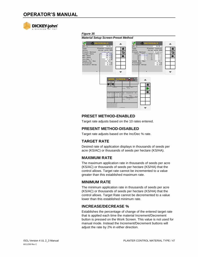
Figure 35
Material Setup Screen-Preset Method
PRESET METHOD-ENABLED
Target rate adjusts based on the 10 rates entered.
PRESENT METHOD-DISABLED
Target rate adjusts based on the Inc/Dec % rate.
TARGET RATE
Desired rate of application displays in thousands of seeds per
acre (KS/AC) or thousands of seeds per hectare (KS/HA).
MAXIMUM RATE
The maximum application rate in thousands of seeds per acre
(KS/AC) or thousands of seeds per hectare (KS/HA) that the
control allows. Target rate cannot be incremented to a value
greater than this established maximum rate.
MINIMUM RATE
The minimum application rate in thousands of seeds per acre
(KS/AC) or thousands of seeds per hectare (KS/HA) that the
control allows. Target Rate cannot be decremented to a value
lower than this established minimum rate.
INCREASE/DECREASE %
Establishes the percentage of change of the entered target rate
that is applied each time the material Increment/Decrement
button is pressed on the Work Screen. This value is not used for
manual mode. Instead the Increment/Decrement buttons will
adjust the rate by 2% in either direction.

OPERATOR’S MANUAL
48 / PLANTER CONTROL MATERIAL TYPE ISO6 Version 4 UL 2_3 Manual
6011258 Rev C
IMPORTANT
The maximum or minimum rates may not be reached if the
% increase or decrease, based off the Target Rate,
exceeds the maximum or minimum rate limits set.
EXAMPLE: Maximum Rate is set for 101. Target Rate is set for
100. If the % increase is set at 2%, the maximum rate of 101 will
not be met because the % increase of 2% would exceed the 101
maximum rate limit.
SEEDS PER REV
Displays the number of seeds that are dropped in one revolution
of the seed disk.
PRECHARGE
See “Using the PreCharge Feature” for more information on
PreCharge setup.
DISTANCE DELAY
The delay in M or FT that the implement must travel before the
Channel is turned on or off. Distance Delay does not function if
the Task Controller is connected and active.
Figure 36
Material Setup Page 2

OPERATOR’S MANUAL
ISO6 Version 4 UL 2_3 Manual PLANTER CONTROL MATERIAL TYPE / 49
6011258 Rev C
NOTE
Press the Arrow button on the Materials screen to view
second screen.
HIGH/LOW POPULATION ALARMS
High and Low Alarm option sets the high and low population limit
values. The entered value is dependent on the target rate.
The High and Low Alarms are entered as a percentage. The
percentage value is referenced in relation to the current channel
target rate setting if rows are assigned to a channel. Otherwise
the alarm will trigger from planter average population.
High Alarm example:
If the Target Rate is 100.0 and the High Alarm is 5.0%, multiply
100.0 x 1.05 (a 5% increase) = 105.0. The alarm will activate at
this population.
Low Alarm example:
If the Target Rate is 100.0 and the Low Alarm is 5.0%, multiply
100.0 x.95 (a 5% decrease) = 95. The alarm will activate at
this rate.
HIGH/LOW ALARM DELAY
Establishes the delay between the detection of a high or low
population alarm condition and the resulting alarm display. The
value is entered in seconds. If the value is set to 10, a row must
be in a high or low population alarm condition continuously for
10 seconds before the alarm is issued.
NOTE
Population is updated every 5 seconds. Setting the Alarm
Delay for under 5 second intervals does not provide any delay
at all.
ROW FAIL RATE
Sets the threshold for row failure alarms. The value is entered in
seeds per second. Both values are adjustable allowing for
numerous combinations. The default value is 2/1 that indicates a
row failure threshold of 2 seeds in 1 second.

OPERATOR’S MANUAL
50 / PLANTER CONTROL MATERIAL TYPE ISO6 Version 4 UL 2_3 Manual
6011258 Rev C
POPULATION ADJUST
Scales the displayed population value to allow for inaccuracies
with seed sensors in certain applications. This is a multiplier of
the monitored population value. For true calculated results, the
value should be set to 100.0%. If the monitored value is reading
low, the value can be increased above 100.0% to achieve the
desired population display. The displayed value is calculated by
the monitored value x population scalar.
(Actual Population - Monitor Population) X 100
Monitor Population
POPULATION FILTER
Stabilizes the monitored population display. For a true population
value, this number should be set to 0.0%. 0.0 is no filtering at all.
99 is the highest level of filtering available. Set the filter to meet
the appropriate level of filtering for your specific use (Advanced
use only).
DISC HIGH/LOW LIMITS
The maximum or minimum RPM at which the seed disc
operates. The control will not allow the seed disc to rotate faster
than the Disc High or Low Limit setting based on the app rate
sensor feedback and any gear ratio entered.
PRODUCT LEVEL ALARM
The product level alarm sets the weight (LBS or KG) to alert of
low seed levels. The entered value is an estimate in
pounds/kilograms (LBS or KG).
GRANULAR SEEDING MATERIAL TYPE
Granular Control setup is used for fertilizer, seeding, and crop
protect applications using hydraulic or electric control systems.
Figure 37
Material Setup - Granular Control

OPERATOR’S MANUAL
ISO6 Version 4 UL 2_3 Manual GRANULAR SEEDING MATERIAL TYPE / 51
6011258 Rev C
TYPE
Read-only field that shows Granular Control for reference.
PRODUCT CLASS
Product class identifies the type of application as either (seeding,
fertilizer, or crop protect e.g. insecticide).
UNITS
The rate units used for the material in pounds per acre (LB/AC),
kilograms per hectare (KG/HA), 1000 seeds per acre (KS/AC),
1000 seeds per hectare (KS/HA), seeds per square foot (S/FT2)
or seeds per square meter (S/M2).
PRESET METHOD ENABLED
The Preset Method table allows 10 user-defined target rates to
be entered. When enabled, target rates is adjusted from the
Work Screen using the Increment/Decrement buttons.
PRESET METHOD DISABLED
When Preset Method is disabled, the target rate on the Work
Screen is adjusted by pressing the Increment/Decrement
buttons. The target rate increases or decreases based on the
Inc/Dec % value set at the Material Configuration screen.
TARGET RATE
Target Rate establishes the desired rate of application according
to the units specified in the Units setting.
MAXIMUM RATE
Maximum Rate establishes the maximum application rate in
pounds per acre (LB/AC) or kilograms per hectare (KG/HA) that
the control allows. Target Rate cannot be incremented to a value
greater than this established maximum rate.

OPERATOR’S MANUAL
52 / GRANULAR SEEDING MATERIAL TYPE ISO6 Version 4 UL 2_3 Manual
6011258 Rev C
MINIMUM RATE
Minimum Rate establishes the minimum application rate in
pounds per acre (LB/AC) or kilograms per hectare (KG/HA) that
the control allows. Target Rate cannot be decremented to a
value lower than this established minimum rate.
INCREASE/DECREASE %
The increment and decrement percent rate establishes the
percentage of change of the entered target rate applied each
time the Increment/ Decrement button is pressed on the
Work Screen.

OPERATOR’S MANUAL
ISO6 Version 4 UL 2_3 Manual GRANULAR SEEDING MATERIAL TYPE / 53
6011258 Rev C
IMPORTANT
The maximum or minimum rates may not be reached
if the % increase or decrease, based off the Target Rate,
exceeds the maximum or minimum rate limits set.
EXAMPLE: Maximum Rate is set for 101. Target Rate is set for
100. If the % increase is set at 2%, the maximum rate of 101 will
not be met because the % increase of 2% would exceed the 101
maximum rate limit.
DENSITY
Density is the weight per volume of material to be dispensed and
is required to convert the spreader constant. May be in units of
LB/FT3, LB/BU, or KG/L.
PRECHARGE
See “Using the PreCharge Feature” for more information on
PreCharge setup.
DISTANCE DELAY
The delay in M or FT that the implement must travel before the
Channel is turned on or off. Distance Delay does not function if
the Task Controller is connected and active.
SEEDS PER POUND
The number (#) of seeds per pound (S/LB) or seeds per kilogram
(S/KG). This setting is used when calculating population values
and triggering alarms. The Seeds per Pound is also used when
material Units are set to KS/AC or Seeds/Ft2 to convert the
target rate to LBS/AC or KG/HA. Editing this setting will update
the Thousand Grain Weight setting.
This number is often found printed on the seed bag. This setting
is only used for materials with Seeding type for Product Class.

OPERATOR’S MANUAL
54 / GRANULAR SEEDING MATERIAL TYPE ISO6 Version 4 UL 2_3 Manual
6011258 Rev C
Figure 38
Material Setup - Granular Control Page 2
NOTE
Press the Arrow button on the Materials screen to view
second screen.
THOUSAND WEIGHT GRAIN
The weight of 1000 seeds in either ounces or grams. This setting
is used when calculating population values and triggering
alarms. The Thousand Grain Weight is also used when material
Units are set to KS/AC or Seeds/Ft2 to convert the target rate to
LBS/AC or KG/HA. Editing this setting will update the Seeds per
Pound setting.
This number can be found by counting out 1000 seeds and
weighing them, or it may be printed on the seed bag. This setting
is only used for materials with Seeding type for Product Class.
HIGH/LOW POPULATION ALARMS
The High and Low Alarm option sets the high and low population
limit values. The entered value is dependent on the target rate.
This setting is only used for materials with seeding type for
Product Class.
The High and Low Alarms are entered as a percentage. The
percentage value is referenced in relation to the Target Rate x
Seed/Lb setting.
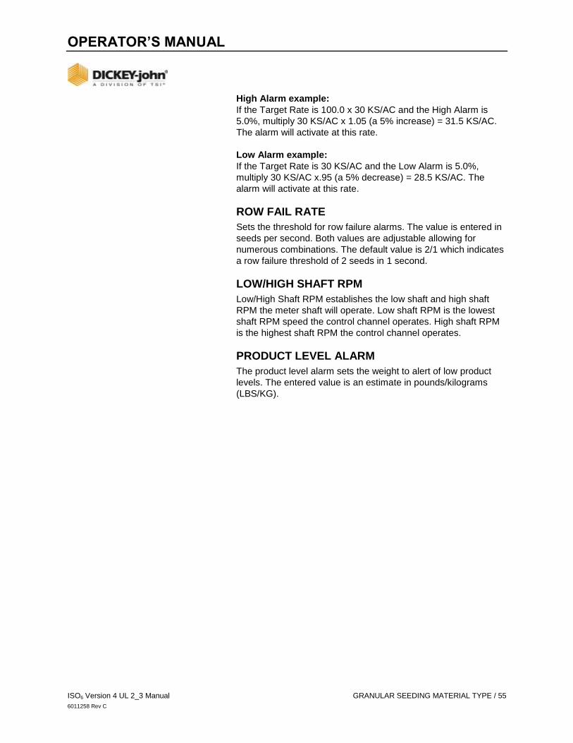
OPERATOR’S MANUAL
ISO6 Version 4 UL 2_3 Manual GRANULAR SEEDING MATERIAL TYPE / 55
6011258 Rev C
High Alarm example:
If the Target Rate is 100.0 x 30 KS/AC and the High Alarm is
5.0%, multiply 30 KS/AC x 1.05 (a 5% increase) = 31.5 KS/AC.
The alarm will activate at this rate.
Low Alarm example:
If the Target Rate is 30 KS/AC and the Low Alarm is 5.0%,
multiply 30 KS/AC x.95 (a 5% decrease) = 28.5 KS/AC. The
alarm will activate at this rate.
ROW FAIL RATE
Sets the threshold for row failure alarms. The value is entered in
seeds per second. Both values are adjustable allowing for
numerous combinations. The default value is 2/1 which indicates
a row failure threshold of 2 seeds in 1 second.
LOW/HIGH SHAFT RPM
Low/High Shaft RPM establishes the low shaft and high shaft
RPM the meter shaft will operate. Low shaft RPM is the lowest
shaft RPM speed the control channel operates. High shaft RPM
is the highest shaft RPM the control channel operates.
PRODUCT LEVEL ALARM
The product level alarm sets the weight to alert of low product
levels. The entered value is an estimate in pounds/kilograms
(LBS/KG).

OPERATOR’S MANUAL
56 / LIQUID FLOW MATERIAL TYPE ISO6 Version 4 UL 2_3 Manual
6011258 Rev C
LIQUID FLOW MATERIAL TYPE
Material setup for liquid flow control of fertilizer and crop
protection applications.
Figure 39
Material Setup Liquid Flow
TYPE
Read-only field that shows Liquid Flow Control for reference.
PRODUCT CLASS
Identifies the type of application as either fertilizer or crop protect
e.g. insecticide.
UNITS
An application rate setting in gallons per acre (GAL/AC) or liters
per hectare (L/HA). Units automatically change with the material
application type selected.
PRESET METHOD ENABLED
The Preset Method table allows 10 user-defined target rates to
be entered. When enabled, target rates can be adjusted from the
Work Screen using the Increment/Decrement buttons.

OPERATOR’S MANUAL
ISO6 Version 4 UL 2_3 Manual LIQUID FLOW MATERIAL TYPE / 57
6011258 Rev C
PRESET METHOD DISABLED
When Preset Method is disabled, the target rate on the
Work Screen can be adjusted by pressing the Material
Increment/Decrement buttons. The target rate increases or
decreases based on the Inc/Dec % value set at the Material
Configuration screen.
TARGET RATE
Target Rate establishes the desired rate of application in gallons
per acre (GAL/AC) or liters per hectare (L/HA).
MAXIMUM RATE
Establishes the maximum application rate in gallons per acre
(GAL/AC) or liters per hectare (L/HA) that the control will allow.
Target Rate cannot be incremented to a value greater than this
established maximum rate.
MINIMUM RATE
Establishes the minimum application rate in gallons per acre
(GAL/AC) or liters per hectare (L/HA) that the control will allow.
Target Rate cannot be decremented to a value lower than this
established minimum rate.
INCREASE/DECREASE %
The Increment/Decrement Percent rate establishes the
percentage of change that is applied each time the
Increment/Decrement button is pressed on the Work Screen.
IMPORTANT
The maximum or minimum rates may not be reached if the
% increase or decrease, based off the Target Rate,
exceeds the maximum or minimum rate limits set.
EXAMPLE: Maximum Rate is set for 101. Target Rate is set for
100. If the % increase is set at 2%, the maximum rate of 101 will
not be met because the % increase of 2% would exceed the 101
maximum rate limit.

OPERATOR’S MANUAL
58 / LIQUID FLOW MATERIAL TYPE ISO6 Version 4 UL 2_3 Manual
6011258 Rev C
Figure 40
Material Setup - Liquid Page 2
NOTE
Press the Arrow button on the Materials screen to view
second screen.
PRECHARGE
See “Using the Precharge Feature” for more information on
Precharge setup.
DISTANCE DELAY
The delay in M or FT that the implement must travel before the
Channel is turned on or off. Distance Delay does not function if
the Task Controller is connected and active.
LOW/HIGH FLOW LIMIT
The Low/High Flow Limit sets the lowest /highest gallons per
minute (G/MN) or liters per minute (L/MN) rate that the control
channel operates.
PRODUCT LEVEL ALARM
Sets the gallons left in the tank to trigger an alarm alerting of low
liquid levels. The entered value is an estimate in gallons (GAL)
or liters (L)

OPERATOR’S MANUAL
ISO6 Version 4 UL 2_3 Manual PLANTER MONITOR MATERIAL TYPE / 59
6011258 Rev C
PLANTER MONITOR MATERIAL TYPE
Planter Monitor is typically used for ground drive applications to
monitor population with high and low alarms.
Figure 41
Planter Monitor Screen
TYPE
Read-only field that shows Planter Monitor for reference.
PRESET METHOD ENABLED
The Preset Method table allows 10 user-defined target rates to
be entered. When enabled, target rates can be adjusted from the
Work Screen using the Increment/Decrement buttons.
PRESET METHOD DISABLED
When Preset Method is disabled, the target rate on the
Work Screen can be adjusted by pressing the Material
Increment/Decrement buttons. The target rate increases or
decreases based on the Inc/Dec % value set at the Material
Configuration screen.
TARGET RATE
Target Rate establishes the desired rate of application in
thousands of seed per acre (KS/AC) or thousands of seeds per
hectare (KS/HA).

OPERATOR’S MANUAL
60 / PLANTER MONITOR MATERIAL TYPE ISO6 Version 4 UL 2_3 Manual
6011258 Rev C
MAXIMUM RATE
Maximum Rate establishes the maximum application rate in
thousands of seed per acre (KS/AC) or thousands of seeds
per hectare (KS/HA) that the control allows. Target Rate
cannot be incremented to a value greater than this established
maximum rate.
MINIMUM RATE
Minimum Rate establishes the minimum application rate in
thousands of seed per acre (KS/AC) or thousands of seeds
per hectare (KS/HA) that the control allows. Target Rate
cannot be decremented to a value lower than this established
minimum rate.
INCREASE/DECREASE %
The Increment/Decrement Percent rate establishes the
percentage of change that is applied each time the
Increment/Decrement button is pressed on the Work Screen.
IMPORTANT
The maximum or minimum rates may not be reached if the
% increase or decrease, based off the Target Rate,
exceeds the maximum or minimum rate limits set.
EXAMPLE: Maximum Rate is set for 101. Target Rate is set for
100. If the % increase is set at 2%, the maximum rate of 101 will
not be met because the % increase of 2% would exceed the 101
maximum rate limit.
SEEDS PER REV
Displays the number of seeds that are dropped in one revolution
of the seed disk.
NOTE
Press the Arrow button on the Materials screen to view
second screen.

OPERATOR’S MANUAL
ISO6 Version 4 UL 2_3 Manual PLANTER MONITOR MATERIAL TYPE / 61
6011258 Rev C
Figure 42
Material Setup-Planter Monitor Page 2
HIGH/LOW POPULATION ALARMS
The High and Low Alarm option sets the high and low population
limit values. The entered value is dependent on the target rate.
The High and Low Alarms are entered as a percentage.
The percentage value is referenced in relation to the
Target Rate x Seed/Lb setting.
HIGH ALARM EXAMPLE:
If the Target Rate is 100.0 x 30 KS/AC and the High Alarm is
5.0%, multiply 30 KS/AC x 1.05 (a 5% increase) = 31.5 KS/AC.
The alarm will activate at this rate.
LOW ALARM EXAMPLE:
If the Target Rate is 30 KS/AC and the Low Alarm is 5.0%,
multiply 30 KS/AC x.95 (a 5% decrease) = 28.5 KS/AC.
The alarm will activate at this rate.
NOTE
Population is updated every 5 seconds. Setting the Alarm
Delay for under 5 second intervals does not provide any delay
at all.
HIGH/LOW ALARM DELAY
Establishes the delay between the detection of a high or low
population alarm condition and the resulting alarm display. The
value is entered in seconds. If the value is set to 10, a row must
be in a high or low population alarm condition continuously for
10 seconds before the alarm is issued.

OPERATOR’S MANUAL
62 / PLANTER MONITOR MATERIAL TYPE ISO6 Version 4 UL 2_3 Manual
6011258 Rev C
ROW FAIL RATE
Sets the threshold for row failure alarms. The value is entered in
seeds per second. Both values are adjustable allowing for
numerous combinations. The default value is 2/1 which indicates
a row failure threshold of 2 seeds in 1 second.
POPULATION ADJUST
Scales the displayed population value to allow for inaccuracies
with seed sensors in certain applications. This is a multiplier of
the monitored population value. For true calculated results, the
value should be set to 100.0%. If the monitored value is reading
low, the value can be increased above 100.0% to achieve the
desired population display. The displayed value is calculated by
the monitored value x population scalar.
(Actual Population - Monitor Population) X 100
Monitor Population
POPULATION FILTER
Stabilizes the monitored population display. For a true population
value, this number should be set to 0.0%. 0.0 is no filtering at all.
99 is the highest level of filtering available. Set the filter to meet
the appropriate level of filtering for your specific use (Advanced
use only).
DISC HIGH/LOW LIMITS
The maximum or minimum RPM at which the seed disc
will operate.
PRODUCT LEVEL ALARM
The product level alarm sets the weight to alert of low seed
levels. The entered value is an estimate in thousands of
seeds (KS)

OPERATOR’S MANUAL
ISO6 Version 4 UL 2_3 Manual GRANULAR MONITOR MATERIAL TYPE / 63
6011258 Rev C
GRANULAR MONITOR MATERIAL TYPE
Select Granular Monitor setup for fertilizer and crop protect
applications using hydraulic control systems.
Figure 43
Granular Monitor Screen
TYPE
Read-only field that shows Granular Monitor for reference.
PRODUCT CLASS
Product class identifies the type of application as either (fertilizer,
seeding or crop protect i.e., insecticide).
UNITS
The rate units used for the material in pounds per acre (LB/AC),
kilograms per hectare (KG/HA).
PRESET METHOD ENABLED
The Preset Method table allows 10 user-defined target rates to
be entered. When enabled, target rates can be adjusted from the
Work Screen using the Increment/Decrement buttons.
PRESET METHOD DISABLED
When Preset Method is disabled, the target rate on the
Work Screen can be adjusted by pressing the Material
Increment/Decrement buttons. The target rate increases or
decreases based on the Inc/Dec % value set at the Material
Configuration screen.

OPERATOR’S MANUAL
64 / GRANULAR MONITOR MATERIAL TYPE ISO6 Version 4 UL 2_3 Manual
6011258 Rev C
TARGET RATE
Target Rate establishes the desired rate of application in pounds
per acre.
MAXIMUM RATE
Maximum Rate establishes the maximum application rate in
pounds per acre (LB/AC) or kilograms per hectare (KG/HA) that
the control will allow. Target Rate cannot be incremented to a
value greater than this established maximum rate.
MINIMUM RATE
Minimum Rate establishes the minimum application rate in
pounds per acre (LB/AC) or kilograms per hectare (KG/HA) that
the control will allow. Target Rate cannot be decremented to a
value lower than this established minimum rate.
INCREASE/DECREASE %
The Increment/Decrement Percent rate establishes the
percentage of change that will be applied each time the
Increment/Decrement button is pressed on the Work Screen.
IMPORTANT
The maximum or minimum rates may not be reached if the
% increase or decrease, based off the Target Rate,
exceeds the maximum or minimum rate limits set.
EXAMPLE: Maximum Rate is set for 101. Target Rate is set for
100. If the % increase is set at 2%, the maximum rate of 101 will
not be met because the % increase of 2% would exceed the 101
maximum rate limit.
DENSITY
Density is the weight per volume of material to be dispensed and
is required to convert the spreader constant. May be in units of
LB/FT3, LB/BU, or KG/L.
SEEDS PER POUND
The number (#) of seeds per pound (S/LB) or seeds per kilogram
(S/KG). This setting is used when calculating population values
and triggering alarms. The Seed Per Pound is also used when
material Units are set to KS/AC or Seeds/Ft2 to convert the
target rate to LBS/AC or KG/HA. Editing this setting will update
the Thousand Grain Weight setting. This number is often found
printed on the seed bag.

OPERATOR’S MANUAL
ISO6 Version 4 UL 2_3 Manual GRANULAR MONITOR MATERIAL TYPE / 65
6011258 Rev C
This setting is only used for materials with Seeding type for
Product Class.
Figure 44
Material Setup-Granular Monitor Page 2
THOUSAND WEIGHT GRAIN
The weight of 1000 seeds in either ounces or grams. This setting
is used when calculating population values and triggering
alarms. The Thousand Grain Weight is also used when material
Units are set to KS/AC or Seeds/Ft2 to convert the target rate to
LBS/AC or KG/HA. Editing this setting will update the Seeds Per
Pound setting.
This number can be found by counting out 1000 seeds and
weighing them, or it may be printed on the seed bag.
This setting is only used for materials with Seeding type for
Product Class.
HIGH/LOW POPULATION ALARMS
Set when an alarm and row indicator displays to warn of a
population problem. The values are % based. The high and low
population values are independent of each other and do not
have to be the same percentage value. This setting is only used
for materials with Seeding type for Product Class.
ROW FAIL RATE
Sets the threshold for row failure alarms. The value is entered in
seeds per second. Both values are adjustable allowing for
numerous combinations. The default value is 2/1 which indicates
a row failure threshold of 2 seeds in 1 second.

OPERATOR’S MANUAL
66 / GRANULAR MONITOR MATERIAL TYPE ISO6 Version 4 UL 2_3 Manual
6011258 Rev C
LOW/HIGH SHAFT RPM
Low/High Shaft RPM establishes the low shaft and high shaft
RPM the meter shaft will operate.
PRODUCT LEVEL ALARM
The product level alarm sets the weight to alert of low seed
levels. The entered value is an estimate in pounds (LBS) or
kilograms (KG).
SHAFT CONTROL
Shaft Control channel defines the setup parameters to regulate a
shaft control input, i.e. spinner, RPM.
Figure 45
Shaft Control
TYPE
Read-only field that shows Shaft Control for reference.
UNITS
An application rate setting in units that automatically change with
the type of material application selected.
OPERATOR’S MANUAL
ISO6 Version 4 UL 2_3 Manual SHAFT CONTROL / 67
6011258 Rev C
PRESET METHOD ENABLED
The Preset Method table allows 10 user-defined target rates to
be entered. When enabled, target rates can be adjusted from the
Work Screen using the Increment/Decrement buttons.
PRESET METHOD DISABLED
When Preset Method is disabled, the target rate on the
Work Screen can be adjusted by pressing the Material
Increment/Decrement buttons. The target rate increases or
decreases based on the Inc/Dec % value set at the Material
Configuration screen.
TARGET RATE
Target Rate establishes the desired rate of application according
to the units specified in the Units setting.
MAXIMUM/MINIMUM RATE
Maximum Rate establishes the maximum application rate in
RPM. Target Rate cannot be incremented to a value greater than
this established maximum rate.
Minimum Rate establishes the minimum application rate in RPM.
Target Rate cannot be decremented to a value lower than this
established minimum rate.
INCREASE/DECREASE %
The Increment/Decrement percent rate establishes the
percentage of change of the entered target rate to be applied
each time the Increment/ Decrement button is pressed on the
Work Screen.
The maximum or minimum rates may not be reached if the %
increase or decrease, based off the target rate, exceeds the
maximum or minimum rate limits set.
NOTE
Press the Arrow button on the Materials screen to view
second screen.

OPERATOR’S MANUAL
68 / SHAFT CONTROL ISO6 Version 4 UL 2_3 Manual
6011258 Rev C
Figure 46
Material Setup - RPM Control Page 2
LOW/HIGH RPM LIMIT
Low/High Shaft RPM establishes the low shaft and high shaft
RPM the meter shaft will operate. Low shaft RPM is the lowest
shaft RPM speed the control channel operates. High shaft RPM
is the highest shaft RPM the control channel operates

OPERATOR’S MANUAL
ISO6 Version 4 UL 2_3 Manual FAN CONTROL / 69
6011258 Rev C
FAN CONTROL
Fan Control channel defines the setup parameters to regulate a
fan control input in RPM.
Figure 47
Fan Control
TYPE
Read-only field that shows Fan Control for reference.
UNITS
An application rate setting in units that automatically change with
the type of material application selected.
PRESET METHOD ENABLED
The Preset Method table allows 10 user-defined target rates to
be entered. When enabled, target rates can be adjusted from the
Work Screen using the Increment/Decrement buttons.
PRESET METHOD DISABLED
When Preset Method is disabled, the target rate on the
Work Screen can be adjusted by pressing the Material
Increment/Decrement buttons. The target rate increases or
decreases based on the Inc/Dec % value set at the Material
Configuration screen.
TARGET RATE
Target Rate establishes the desired rate of application in RPM.

OPERATOR’S MANUAL
70 / FAN CONTROL ISO6 Version 4 UL 2_3 Manual
6011258 Rev C
MAXIMUM/MINIMUM RATE
Maximum Rate establishes the maximum application rate in
RPM. Target Rate cannot be incremented to a value greater than
this established maximum rate.
Minimum Rate establishes the minimum application rate in RPM.
Target Rate cannot be decremented to a value lower than this
established minimum rate.
INCREASE/DECREASE %
The Increment/Decrement percent rate establishes the
percentage of change of the entered target rate to be applied
each time the Increment/ Decrement button is pressed on the
Work Screen.
The maximum or minimum rates may not be reached if the %
increase or decrease, based off the target rate, exceeds the
maximum or minimum rate limits set.
NOTE
Press the Arrow button on the Materials screen to view
second screen.
Figure 48
Material Setup - Fan Page 2
LOW/HIGH RPM LIMIT
Low/High Shaft RPM establishes the low shaft and high shaft
RPM the meter shaft will operate. Low shaft RPM is the lowest
shaft RPM speed the control channel operates. High shaft RPM
is the highest shaft RPM the control channel operates.

OPERATOR’S MANUAL
ISO6 Version 4 UL 2_3 Manual CONTROL CHANNEL SETUP / 71
6011258 Rev C
CONTROL CHANNEL SETUP Up to eight material application control channels are
available based on the number of purchased channels and
corresponding hardware.
ASSIGN A CONTROL CHANNEL The Controls screen on initial setup is blank. Adding, deleting,
and editing channel setup parameters are defined at this screen.
As channels are configured and saved in sequential order, the
Controls screen identifies the channel type and material
assigned. A channel type cannot be changed after setup.
The channel must be removed and a new one created.
Materials may be assigned to channels from the Materials page.
Once a channel is created, select the channel to edit
setup parameters.
NOTE
It is recommended that materials are created before
configuring channels. A default material will be created for the
specific control channel type if no materials are set up.
TO ADD AND EDIT A CONTROL CHANNEL:
1. Press the CONTROLS button.
2. Press the ADD CHANNEL button to select the control
channel type.
- Select the desired Channel Type button.
3. The selected channel type now appears on the
Controls screen.
4. Press to highlight and select the channel.
5. Press the EDIT button to open the channel and establish
channel parameters. Reference the “Control Channel
Type” section.
Figure 49
Select a Control Channel Type

OPERATOR’S MANUAL
72 / CONTROL CHANNEL SETUP ISO6 Version 4 UL 2_3 Manual
6011258 Rev C
DELETE A CONTROL CHANNEL
A control channel and its parameters can be removed from the
Controls screen. Deleting a channel clears the entered
parameters for the channel.
TO REMOVE A CHANNEL:
1. At the Controls screen, press to select and highlight the
control channel.
2. Press the REMOVE button.
3. Press the Checkmark button to acknowledge.
- Channel parameters are cleared and the channel can be
setup as a new control type in the future.
- Press the Cancel ‘X’ button to abort.
Figure 50
Clear a Control Channel

OPERATOR’S MANUAL
ISO6 Version 4 UL 2_3 Manual CONTROL CHANNEL SETUP / 73
6011258 Rev C
COPY A CONTROL CHANNEL
A control channel’s setup parameters can be copied to
another channel.
1. Select to highlight the control channel to copy.
2. Press the COPY button.
- The copied channel appears in the next open
channel space.
Figure 51
Clear a Channel
CHANNEL LINKING
Material application control channels can be linked together in a
master/ subordinate relationship. This allows for simultaneous
on/off and rate control from the Work Screen.
TO LINK CHANNELS:
1. At the Control screen, press the CHANNEL LINKING button.
2. At the Channel Linking screen, press the ADD LINK button.
3. Select the link type as:
- Rate: linking the rates of multiple channels.
- On/Off: Linking channels to simultaneously turn
ON and OFF.
- Master/Subordinate: Links a master/subordinate output
to simultaneously turn on/off channels, i.e. planter
control channel/fan.
- Accessory: Allows an accessory alarm to turn the linked
channel(s) off.
4. Press the channels input box to select the channels to link.
- Continue to press the ADD LINK button until are links
are complete.
5. When finished, press the Back button.
6. The new link type and channels display on the Channel
Linking screen.
7. To edit a link, select a specific link and press the EDIT
button to open and make any changes.

OPERATOR’S MANUAL
74 / CONTROL CHANNEL SETUP ISO6 Version 4 UL 2_3 Manual
6011258 Rev C
Figure 52
Linking Channels
CONTROL CHANNEL TYPE
A material application channel can be assigned as Planter
Control, Planter Monitor, Granular Control, Granular Monitor,
Liquid Flow, Fan Control, Shaft Control, or IRC.
TO EDIT CONTROL CHANNEL PARAMETERS:
At the Controls screen, highlight the channel and press the
EDIT button.

OPERATOR’S MANUAL
ISO6 Version 4 UL 2_3 Manual PLANTER CONTROL CHANNEL / 75
6011258 Rev C
PLANTER CONTROL CHANNEL
A Planter Control channel contains the parameters to control the
application rate of a row crop planter.
Figure 53
Planter Control Setup
MATERIAL NAME
Display the material name assigned to the channel. This value
can be changed by editing Configurations in the Material screen.
CONTROL MODE
Auto-Control Channel is calculating application rates
based on ground speed and row spacing under normal
operating conditions.
MANUAL WITH FEEDBACK - Overrides the current system
when not operating properly, e.g. Faulty coil. Using the
increment/decrement buttons at the main operate screen will set
the rate for the control channel. Manual mode with feedback
shows the actual application rate applied based on actual ground
speed and constants.
MANUAL WITHOUT FEEDBACK - Overrides the current
system when not operating properly, e.g. Bad feedback sensor.
Using the increment/ decrement buttons at the work screen will
set the rate for the control channel. No application rate feedback
will display.

OPERATOR’S MANUAL
76 / PLANTER CONTROL CHANNEL ISO6 Version 4 UL 2_3 Manual
6011258 Rev C
NOTE
DICKEY-john proportional valves operate at 100 Hz.
NOTE
The correct number of pulses generated for one revolution
must be determined for sensors other than DICKEY-john.
DRIVE TYPE PWM (PULSE WIDTH MODULATION)
A valve, usually hydraulic, which varies the oil flow to a hydraulic
motor proportioned to electric current supplied. This type of valve
consists of a flow cartridge and coil assembly.
DRIVE FREQUENCY
Specifies the frequency for the proportional valve installed. The
recommended setting for this option should be specified from the
specific valve manufacturer.
INPUT FILTER
Provides a setting for the amount of filtering applied to the
feedback frequency of the control channel.
IMPORTANT
It is NOT recommended to change the Filter setting. Any
adjustments could result in the channel not operating
properly. If adjustments are made, a valve calibration
must be performed.
GEAR RATIO
Specifies the actual ratio from the application rate sensor to the
seed meter. This specifies the number of revolutions the
application rate sensor turns in relation to one revolution the
seed meter turns.
NOTE
The correct number of pulses generated for one revolution
must be determined for sensors other than DICKEY-john.
SENSOR CONSTANT
Establishes the number of pulses for one revolution of the
application rate sensor. If a standard DICKEY-john application
rate sensor is used, the value should be set to 360.

OPERATOR’S MANUAL
ISO6 Version 4 UL 2_3 Manual PLANTER CONTROL CHANNEL / 77
6011258 Rev C
SEED ROW ASSIGNMENT
Enter the first and last number of the seed rows assigned to the
control channel.
NUMBER (#) OF SEED ROWS
Displays the total number of seed rows assigned to the
control channel.
CHANNEL WIDTH
The overall row width assigned to a specific channel. Width
calculation is determined by the number of rows assigned to the
channel multiplied by the row spacing defined on the Rows page.
GRANULAR CONTROL CHANNEL
A granular control channel controls granular application on
planters, drills, air seeders, and air carts.
Figure 54
Granular Control Channel
MATERIAL NAME
Display the material assigned to the channel. This value can be
changed by editing the configurations in the Material screen.
TANK NUMBER
Enter the tank number linked to the channel for control
of material.
CONTROL MODE
Auto-Control Channel is calculating application rates
based on ground speed and row spacing under normal
operating conditions.

OPERATOR’S MANUAL
78 / GRANULAR CONTROL CHANNEL ISO6 Version 4 UL 2_3 Manual
6011258 Rev C
MANUAL WITH FEEDBACK - Overrides the current system
when not operating properly, e.g. faulty coil. Using the
Increment/Decrement buttons at the Main Operate screen will
set the rate for the control channel. Manual Mode with Feedback
shows the actual application rate applied based on actual ground
speed and constants.
MANUAL WITHOUT FEEDBACK - Overrides the current
system when not operating properly, e.g. bad feedback sensor.
Using the Increment/ Decrement buttons at the Work Screen will
set the rate for the control channel. No application rate feedback
will display.
DRIVE TYPE PWM (PULSE WIDTH MODULATION)
A valve, usually hydraulic, which varies the oil flow to a hydraulic
motor proportioned to electric current supplied. This type of valve
consists of a flow cartridge and coil assembly.
NOTE
DICKEY-john Servo valves operate at 40 Hz; DICKEY-john
Proportional Valves operate at 100 Hz.
NOTE
The correct number of pulses generated for one revolution
must be determined for sensors other than DICKEY-john.
SERVO
A ball valve or butterfly valve that is driven by an electric motor
gearbox and the valve is installed in the tank return line.
DRIVE FREQUENCY
Specifies the frequency for the proportional valve installed. The
recommended setting for this option should be specified from the
valve manufacturer.
FILTER
The amount of filtering applied to the frequency feedback of the
control channel.
IMPORTANT
It is NOT recommended to change the Filter setting. Any
adjustments could result in the channel not operating
properly. If adjustments are made a valve calibration must
be performed.

OPERATOR’S MANUAL
ISO6 Version 4 UL 2_3 Manual GRANULAR CONTROL CHANNEL / 79
6011258 Rev C
SENSOR CONSTANT
Establishes the number of pulses for one revolution of the
metering unit. If a standard DICKEY-john application rate
sensor is used, the value should be set to 360.
GEAR RATIO
Specifies the actual ratio from the application rate sensor to
the output shaft. This specifies the number of revolutions the
application rate sensor turns in relation to one revolution the
final output shaft.
SPREADER CONSTANT
How many pulses the application rate sensor produces per
volume of material discharged.
SEED ROW ASSIGNMENT
Enter the first and last number of seed rows assigned to the
control channel.
NUMBER (#) OF SEED ROWS
Displays the total number of seed rows assigned to the
control channel.
CHANNEL WIDTH
Granular Seeding-The implement width for rows assigned
to a channel.
Granular Fertilizer-The fertilizer spread width assigned
to a channel.
FLUSH ENABLE
Flush Enable is a manual override mode that opens the valve
and dispenses granular fertilizer, granular seed, or liquid material
for a period of time in relation to a user-defined flush speed.
The Flush Enable feature can only be activated when the tractor
is stopped.
To Activate:
1. At the Controls screen, change Flush Disabled to Enabled.
Flush Enable must be activated at the Control screen before
the Flush Ground Speed feature is displayed on the Speed
setup screen.
- A Flush Ground Speed greater than 0 must be entered
on the Speed setup screen for this feature to operate.

OPERATOR’S MANUAL
80 / GRANULAR CONTROL CHANNEL ISO6 Version 4 UL 2_3 Manual
6011258 Rev C
Figure 55
Flush Enable
RATE REDUCTION
Return to Tank
As the channel’s applied width reduces, the shaft speed is not
reduced. Typically used for machines that have diverter shutoffs
that returns seed to the tank.
Meter Rate
As the channel’s applied width reduces, the shaft speed is
reduced to maintain the sample application rate. Typically
used for machines that have row shutoff that block seed flow
to the row.
LIQUID FLOW CONTROL CHANNEL
Control setup parameters for liquid flow control applications.
Figure 56
Liquid Flow Control

OPERATOR’S MANUAL
ISO6 Version 4 UL 2_3 Manual LIQUID FLOW CONTROL CHANNEL / 81
6011258 Rev C
MATERIAL NAME
Display the material assigned to the channel. This value can be
changed by editing the configurations in the Material screen.
TANK NUMBER
Enter the Tank Number linked to the channel that controls
material application.
CONTROL MODE
Auto-Control Channel is calculating application rates
based on ground speed and row spacing under normal
operating conditions.
MANUAL WITH FEEDBACK - Overrides the current system
when not operating properly, e.g. faulty coil. Using the
Increment/Decrement buttons at the Main Operate screen will
set the rate for the control channel. Manual Mode with Feedback
shows the actual application rate applied based on actual ground
speed and constants.
MANUAL WITHOUT FEEDBACK - Overrides the current
system when not operating properly, e.g. bad feedback sensor.
Using the Increment/ Decrement buttons at the Work Screen will
set the rate for the control channel. No application rate feedback
will display.
DRIVE TYPE PWM (PULSE WIDTH MODULATION)
A valve, usually hydraulic, which varies the oil flow to a hydraulic
motor proportioned to electric current supplied. This type of valve
consists of a flow cartridge and coil assembly.
SERVO
A ball valve or butterfly valve that is driven by an electric motor
gearbox and the valve is installed in the tank return line.
NOTE
DICKEY-john Servo valves operate at 40 Hz; DICKEY-john
Proportional valves operate at 100 Hz.
DRIVE FREQUENCY
Specifies the frequency for the proportional or servo valve
installed. The recommended setting for this option should be
specified from the valve manufacturer.
INPUT FILTER
An adjustment setting for the amount of filtering applied to the
flow meter feedback frequency of the control channel.

OPERATOR’S MANUAL
82 / LIQUID FLOW CONTROL CHANNEL ISO6 Version 4 UL 2_3 Manual
6011258 Rev C
IMPORTANT
It is NOT recommended to change the Input Filter. Any
adjustments could result in the channel not operating
properly. If adjustments are made, a valve calibration
must be performed.
K-FACTOR
How many pulses are produced by the sensor per gallon (liter) of
liquid through the flow meter? A flow meter calibration is
recommended for better accuracy. However, if known, the
K-Factor can be entered manually. If not, a flow meter calibration
is required. Refer to the Liquid Flow Calibration section for
additional information.
NOZZLES
Enter the first and last number of nozzles assigned to a channel.
NUMBER OF NOZZLES
The total number of nozzles assigned to a channel.
NOZZLE SPACING
The distance in inches (centimeters) between nozzles on the
spray bar for broadcast operations. The value to enter is
determined by measuring the distance between nozzles to the
nearest 1/10th.
CHANNEL WIDTH
Channel Width is an automatic calculation of the overall channel
width based from the number of nozzles times width spacing.
FLUSH ENABLE
Refer to (Figure 57).
Flush Enable is a manual override mode that opens the valve
and dispenses granular fertilizer, granular seed, or liquid material
for a period of time in relation to a user-defined flush speed. The
Flush Enable feature can only be activated when the tractor
is stopped.

OPERATOR’S MANUAL
ISO6 Version 4 UL 2_3 Manual LIQUID FLOW CONTROL CHANNEL / 83
6011258 Rev C
To Activate Flush Enable:
1. Change Flush Disable to Enable. Flush Enable must be
activated before the Flush Ground Speed feature displays on
the Ground Speed Setup screen.
- A Flush Ground Speed greater than 0 must be entered
on the Ground Speed setup screen for this feature
to operate.
Figure 57
Flush Enable

OPERATOR’S MANUAL
84 / PLANTER MONITOR CHANNEL ISO6 Version 4 UL 2_3 Manual
6011258 Rev C
PLANTER MONITOR CHANNEL
Control setup parameters for planter monitor applications.
IMPORTANT
When using an application rate sensor, select the
appropriate Drive Type and install the application rate
sensor to the corresponding feedback.
Figure 58
Planter Monitor Channel Setup
MATERIAL NAME
Display the material assigned to the channel.
CONTROL MODE
FEEDBACK - Overrides the current system when not operating
properly, e.g. faulty coil. Using the Increment/Decrement buttons
at the Main Operate screen sets the rate for the control channel.
Manual Mode with Feedback shows the actual application rate
applied based on actual ground speed and constants.
NO FEEDBACK - Overrides the current system when not
operating properly, i.e., bad feedback sensor. Using the
Increment/Decrement buttons at the Work Screen will set the
flow rate for the control channel. No application rate feedback
will display.

OPERATOR’S MANUAL
ISO6 Version 4 UL 2_3 Manual PLANTER MONITOR CHANNEL / 85
6011258 Rev C
DRIVE TYPE PWM (PULSE WIDTH MODULATION)
A valve, usually hydraulic, which varies the oil flow to a hydraulic
motor proportioned to electric current supplied. This type of valve
consists of a flow cartridge and coil assembly.
INPUT FILTER
An adjustment setting for the amount of filtering applied to the
feedback frequency feedback of the control channel.
IMPORTANT
It is NOT recommended to change the Input Filter. Any
adjustments could result in the channel not operating
properly. If adjustments are made, a valve calibration
must be performed.
GEAR RATIO
Specifies the actual ratio from the application rate sensor to
the output shaft. This specifies the number of revolutions the
application rate sensor turns in relation to one revolution the
final output shaft turns.
SENSOR CONSTANT
Establishes the number of pulses for one revolution of the
metering unit. If a DICKEY-john application rate sensor is used,
the value should be set to 360.
SEED ROW ASSIGNMENT
Enter the first and last number of seed rows assigned to
the control.
NUMBER (#) OF SEED ROWS
Displays the total number of seed rows assigned to the
control channel.
CHANNEL WIDTH
Enter the width of rows assigned to a specific channel.
Width calculation can be determined by number of planter
rows assigned to the channel multiplied by the row spacing.

OPERATOR’S MANUAL
86 / GRANULAR MONITOR CHANNEL ISO6 Version 4 UL 2_3 Manual
6011258 Rev C
GRANULAR MONITOR CHANNEL
The following constants define the parameters for
Granular Monitor.
IMPORTANT
When using an application rate sensor, select the
appropriate Drive Type and install the application rate
sensor on the corresponding feedback.
Figure 59
Granular Monitor Control Channel
MATERIAL NAME
Display the material assigned to the channel. This value can be
changed by editing the configurations in the Material screen.
CONTROL MODE
FEEDBACK - Overrides the current system when not operating
properly, i.e., faulty coil. Using the Increment/Decrement buttons
at the Main Operate screen will set the rate for the control
channel. Manual Mode with Feedback shows the actual
application rate applied based on actual ground speed and
constants.
NO FEEDBACK - Overrides the current system when not
operating properly, i.e., bad feedback sensor. Using the
Increment/Decrement buttons at the Work Screen will set the
flow rate for the control channel. No application rate feedback
will display.

OPERATOR’S MANUAL
ISO6 Version 4 UL 2_3 Manual GRANULAR MONITOR CHANNEL / 87
6011258 Rev C
DRIVE TYPE PWM (PULSE WIDTH MODULATION)
A valve, usually hydraulic, which varies the oil flow to a hydraulic
motor proportioned to electric current supplied. This type of valve
consists of a flow cartridge and coil assembly.
INPUT FILTER
An adjustment setting for the amount of filtering applied to the
feedback frequency feedback of the control channel.
IMPORTANT
It is NOT recommended to change the Input Filter. Any
adjustments could result in the channel not operating
properly. If adjustments are made, a valve calibration
must be performed.
SENSOR CONSTANT
Establishes the number of pulses for one revolution of the
metering unit. If a DICKEY-john application rate sensor is used,
the value should be set to 360.
GEAR RATIO
Specifies the actual ratio from the application rate sensor to the
output shaft. This specifies the number of revolutions the
application rate sensor turns in relation to one revolution the final
output shaft turns.
SPREADER CONSTANT
How many pulses the application rate sensor produces per
volume of material discharged.
SEED ROW ASSIGNMENT
Enter the first and last number of seed rows assigned to the
control channel.
NUMBER (#) OF SEED ROWS
Displays the total number of seed rows assigned to the
control channel.
CHANNEL WIDTH
Enter the width of rows assigned to a specific channel. Width
calculation can be determined by number of planter rows
assigned to the channel multiplied by the row spacing.

OPERATOR’S MANUAL
88 / FAN CONTROL ISO6 Version 4 UL 2_3 Manual
6011258 Rev C
FAN CONTROL
The following constants define the parameters for fan control.
Figure 60
Fan Control Channel Setup
MATERIAL NAME
Display the material assigned to the channel. This value can be
changed by editing the configurations in the Material screen.
CONTROL MODE
Auto-Control Channel is calculating application rates based on
ground speed and row spacing under normal operating
conditions.
MANUAL WITH FEEDBACK - Overrides the current system
when not operating properly, e.g. faulty coil. Using the
Increment/Decrement buttons at the Main Operate screen will
set the rate for the control channel. Manual Mode with Feedback
shows the actual application rate applied based on actual ground
speed and constants.
MANUAL WITHOUT FEEDBACK - Overrides the current
system when not operating properly, e.g. bad feedback sensor.
Using the Increment/ Decrement buttons at the Work Screen will
set the rate for the control channel. No application rate feedback
will display.

OPERATOR’S MANUAL
ISO6 Version 4 UL 2_3 Manual FAN CONTROL / 89
6011258 Rev C
DRIVE TYPE PWM (PULSE WIDTH MODULATION)
A valve, usually hydraulic, which varies the oil flow to a hydraulic
motor proportioned to electric current supplied. This type of valve
consists of a flow cartridge and coil assembly.
DRIVE FREQUENCY
Specifies the frequency for the proportional valve installed. The
recommended setting for this option should be specified from the
specific valve manufacturer.
INPUT FILTER
An adjustment setting for the amount of filtering applied to the
feedback frequency feedback of the control channel.
IMPORTANT
It is NOT recommended to change the Input Filter. Any
adjustments could result in the channel not operating
properly. If adjustments are made, a valve calibration
must be performed.
SENSOR CONSTANT
Establishes the number of pulses for one revolution of the
application rate sensor. If a standard DICKEY-john application
rate sensor is used, the value should be set to 360.
IMPLEMENT UP
Disabled
The control loop runs regardless of implement lift state. If
sufficient hydraulic capacity is not available, alarms may
trigger if the fan is not maintaining set point.
Locked
When the implement is raised the control loop is stopped and
output is frozen at its previous value. If you don’t have enough
hydraulic capacity and the fan is not maintaining set point
prevents alarms for occurring even though fan is still not
working properly.

OPERATOR’S MANUAL
90 / FAN CONTROL ISO6 Version 4 UL 2_3 Manual
6011258 Rev C
DISABLE CONTROL ON CONTROL FAILURE ALARM
Select “Enabled” to turn off ALL non-fan control channels when
the RPM value of the sensor falls below the low alarm level
setting.
The two settings include:
ENABLED - control channels shut down when the RPM
value falls below the low warning setting.
DISABLED - will disable the function. Control channels
continue to operate normally regardless of the RPM value.
However, when the low RPM state occurs, the information
alarm still occurs.
SHAFT CONTROL
The following constants define the parameters for Shaft Control.
Figure 61
Shaft Control Channel Setup
MATERIAL NAME
Display the material assigned to the channel. This value can be
changed by editing the configurations in the Material screen.

OPERATOR’S MANUAL
ISO6 Version 4 UL 2_3 Manual FAN CONTROL / 91
6011258 Rev C
CONTROL MODE
Auto-Control Channel is calculating application rates based on
ground speed and row spacing under normal operating
conditions.
MANUAL WITH FEEDBACK - Overrides the current system
when not operating properly, e.g. faulty coil. Using the
Increment/Decrement buttons at the Main Operate screen will
set the rate for the control channel. Manual Mode with Feedback
shows the actual application rate applied based on actual ground
speed and constants.
MANUAL WITHOUT FEEDBACK - Overrides the current
system when not operating properly, e.g. bad feedback sensor.
Using the Increment/ Decrement buttons at the Work Screen will
set the rate for the control channel. No application rate feedback
will display.
DRIVE TYPE PWM (PULSE WIDTH MODULATION)
A valve, usually hydraulic, which varies the oil flow to a hydraulic
motor proportioned to electric current supplied. This type of valve
consists of a flow cartridge and coil assembly.
DRIVE FREQUENCY
Specifies the frequency for the proportional valve installed. The
recommended setting for this option should be specified from the
specific valve manufacturer.
INPUT FILTER
An adjustment setting for the amount of filtering applied to the
feedback frequency feedback of the control channel.
IMPORTANT
It is NOT recommended to change the Input Filter. Any
adjustments could result in the channel not operating
properly. If adjustments are made, a valve calibration
must be performed.
SENSOR CONSTANT
Establishes the number of pulses for one revolution of the
application rate sensor. If a standard DICKEY-john application
rate sensor is used, the value should be set to 360

OPERATOR’S MANUAL
92 / IRC ISO6 Version 4 UL 2_3 Manual
6011258 Rev C
INDIVIDUAL ROW CONTROL (IRC)
The following constants define the parameters for Individual
Row Control.
Figure 62
IRC Channel Setup
MATERIAL NAME
Display the material assigned to the channel. This value can be
changed by editing the configurations in the Material screen.
GEAR RATIO
Specifies the actual ratio from the application rate sensor to the
output shaft. This specifies the number of revolutions the
application rate sensor turns in relation to one revolution the final
output shaft turns.
NUMBER (#) OF SEED ROWS
Specifies the total number of seed rows assigned to the
control channel.
SEED ROW ASSIGNMENT
Display the first and last number of seed rows assigned to the
control channel.

OPERATOR’S MANUAL
ISO6 Version 4 UL 2_3 Manual DROP SPREADER / 93
6011258 Rev C
DROP SPREADER
The following constants define the parameters for
Drop Spreader.
Figure 63
Drop Spreader Channel Setup
MATERIAL NAME
Display the material assigned to the channel.
SPINNER OUTPUT PWM (PULSE WIDTH MODULATION)
A valve, usually hydraulic, which varies the oil flow to a hydraulic
motor proportioned to electric current supplied. This type of valve
consists of a flow cartridge and coil assembly.
GATE OUTPUT
SERVO
A ball valve or butterfly valve that is driven by an electric motor
gearbox and the valve is installed in the tank return line.
DRIVE FREQUENCY
Specifies the drive frequency for the PWM channel on the
Spinner Output. The recommended setting for this option should
be specified from the valve manufacturer.

OPERATOR’S MANUAL
94 / CALIBRATIONS ISO6 Version 4 UL 2_3 Manual
6011258 Rev C
CALIBRATIONS-VALVE AND SPREADER
Valve calibrations are required for proper system operation for
planter, granular, and liquid flow channels. Some calibration
screens vary based on control channel type.
PLANTER CONTROL AND GRANULAR VALVE CALIBRATION
Performing a valve calibration is required for planter, granular,
fan, shaft, and liquid flow channels to set system parameters and
should be performed for best results. A Valve Calibration button
appears on the control channel screen if this step is appropriate
for the assigned channel type.
TIP: Valve calibration steps 1-10 are the same when performing
for Planter, Granular, Liquid Flow, Fan and Shaft Control.
CAUTION
Hoppers are assumed to be empty for this calibration. If
loaded, material may dispense from the meter.
NOTE
Refer to the System Tests section for using a remote test
switch during a valve calibration.
PERFORM A VALVE CALIBRATION
1. At the Controls screen, press the VALVE CALIBRATION
button to access the Valve Calibration screen (Figure 64).
- If necessary, run Limit Output before running the Valve
Calibration. Refer to the Limit Output section.
2. Move the implement to the “raised” position.
3. Apply the tractor brakes and lock in the applied position.
4. Put the transmission in “park” or in a locked, neutral position.
- Verify disc speed high limit is set correctly. Valve
calibration will try and obtain the high disc speed.
DANGER
When the START key is engaged, the machine will
become operational. All necessary precautions must be
taken to ensure user safety. Failure to practice all
necessary caution may result in serious injury or death.

OPERATOR’S MANUAL
ISO6 Version 4 UL 2_3 Manual CALIBRATIONS / 95
6011258 Rev C
5. Start the tractor and engage the hydraulic system.
6. Run the engine at normal operating speed until the hydraulic
fluid is at normal operating temperature.
7. Press the START button.
8. The valve calibration immediately starts.
9. Keep the hydraulics engaged until the calibration is
complete. The calibration may take a minute up to several
minutes. Each calibration step is monitored at the bottom of
the display.
10. When the calibration is complete, the control shuts down
automatically. All calibration data is automatically stored.
Figure 64
Valve Calibration
LIMIT OUTPUT (GRANULAR)
It is necessary to limit the output of the control channel before
running a valve calibration in the event that system capacities
are greater than the actual desired capacities. These features
allow setting the maximum output of the channel to prevent
machine damage.
TO PERFORM A LIMIT OUTPUT:
1. At the Valve Calibration screen, press the LIMIT OUTPUT
button to access the Limit Output screen.
2. Move the implement to the “raised” position.
3. Apply the tractor brakes and lock in the applied position.

OPERATOR’S MANUAL
96 / CALIBRATIONS ISO6 Version 4 UL 2_3 Manual
6011258 Rev C
4. Put the transmission in “park” or in a locked, neutral position.
5. Engage hydraulic system.
6. Run engine at normal operating RPM until hydraulic fluid is
at normal operating temperature.
7. To change the valve position, press the Increment or
Decrement buttons repeatedly until the desired maximum
output value is reached.
8. Press the START button and the valve calibration
immediately begins.
The calibration runs using the new max flow value.
Figure 65
Limit Output Screen
OPERATOR’S MANUAL
ISO6 Version 4 UL 2_3 Manual CALIBRATIONS / 97
6011258 Rev C
SPREADER CALIBRATION (GRANULAR)
NOTE
Refer to the System Tests section for using a remote test
switch during a spreader calibration.
A Spreader Constant Calibration requires a catch test to
determine the spreader constant. This function is only available
for granular seed and fertilizer applications.
PERFORM A SPREADER CALIBRATION
IMPORTANT
A valve calibration should be performed before a
spreader calibration.
1. Load hopper with material.
2. Move implement to the raised position.
3. Apply tractor brakes and lock in applied position.
4. Put transmission in park or in a locked, neutral position.
5. Engage hydraulic system.
6. Run engine at normal operating RPM until hydraulic fluid is
at normal operating temperature.
7. At the Controls screen, press the SPREAD CAL button.
8. Press the SHAFT TURN button to fill seed/fertilizer metering
system before starting calibration.
9. At the Calibration screen, enter the following values:
- Density - Enter product weight per volume in 1 lbs/ft3.
- Target Meter RPM - Enter the RPM at which the output
meter shaft will turn during the calibration.
- # of Meter Revs - Enter number of total revolutions the
meter will turn during the calibration. This determines the
length of the test and is more accurate the higher the
number.
10. At the Calibration screen, press the START button.
11. Weigh and enter lbs. of material dispensed in the Amount
Dispensed field.
12. Press the SAVE button.
13. The new spreader constant automatically calculates and is
entered for this material.

OPERATOR’S MANUAL
98 / CALIBRATIONS ISO6 Version 4 UL 2_3 Manual
6011258 Rev C
Figure 66
Granular Control Spreader Calibration
SPREADER CONSTANTS DEFINED
DENSITY
Relative granular density as represented by the weight of
product per volume (lb/ft3, lb/bu, kg/L) If not known, enter
a value of lb/ft3.
SPREADER CONSTANT
Determines how many pulses the application rate sensor
produces per volume of material discharged.
TARGET METER RPM
The speed at which the output meter shaft turns while the
calibration is performed.

OPERATOR’S MANUAL
ISO6 Version 4 UL 2_3 Manual CALIBRATIONS / 99
6011258 Rev C
NUMBER (#) METER REVS
The number of revolutions the meter turns during the calibration.
This will constitute the length of the test. The higher the number,
the more accurate the calibration.
NOTE
If performing a Spreader Calibration on a box type drill, catch
the output of a few seed meters, average the weight measured
from these meters, and multiply this average weight by the
total number of meters on the drill. Enter this weight for the
Amount Dispensed value.
PULSE COUNT
A pulse count that is produced from the feedback sensor. This
number is informational only.
NEW SPREADER CONSTANT
After the spreader calibration is performed and the amount is
entered, press the SAVE button to accept the new constant.
AMOUNT DISPENSED
Enter the amount (Lbs/Kg) dispensed after performing the
spreader constant calibration. The amount dispensed number
is used with pulse count and density to calculate the new
spreader constant.
SHAFT TURN
The SHAFT TURN button turns the shaft one (1) gear revolution
and fills the seed meter for instant seed flow when the control is
turned on.
The meter should be full of material before the calibration
is started.
LIQUID FLOW CALIBRATION
Performing a Limit Output, Valve Calibration, and K-Factor
Calibration are recommended for a Liquid Flow control
channel type.
PERFORM A VALVE CALIBRATION
Follow valve calibration steps 1-10 listed in planter and granular
control valve calibration section.

OPERATOR’S MANUAL
100 / CALIBRATIONS ISO6 Version 4 UL 2_3 Manual
6011258 Rev C
Figure 67
Liquid Flow Valve Calibration and Limit Output

OPERATOR’S MANUAL
ISO6 Version 4 UL 2_3 Manual LIMIT OUTPUT / 101
6011258 Rev C
LIMIT OUTPUT
It is necessary to limit the output of the control channel before
running a valve calibration in the event that system capacities
are greater than the actual desired capacities. These features
allow setting the maximum output of the channel to prevent
machine damage.
PERFORM A LIMIT OUTPUT:
1. At the Valve Calibration screen, press the
LIMIT OUTPUT button.
2. Move the implement to the “raised” position.
3. Apply the tractor brakes and lock in the applied position.
4. Put the transmission in “park” or in a locked, neutral position.
5. Engage hydraulic system.
6. Run engine at normal operating RPM until hydraulic fluid is
at normal operating temperature.
7. To change the valve position, press the Increment or
Decrement buttons repeatedly until the desired maximum
output value is reached.
8. Press the START button and the valve calibration
immediately begins.
The calibration runs using the new max flow value.
K-FACTOR CALIBRATION
NOTE
Refer to the System Tests section for using a remote test
switch during a K-Factor calibration.
To determine the actual K-Factor of a system, water should be
dispensed through the system and measured. The calibration
procedure will accumulate the pulse. At the end of the calibration
procedure, the operator enters the amount dispensed. This
number becomes the actual K-Factor instead of the one
stamped on the flow meter body. The more liquid passing
through the system during calibration increases the degree
of K-Factor accuracy.
100% CATCH TEST
This is the recommended method because a larger volume of
liquid passes through the entire sprayer system making errors in
weighing a smaller factor.
1. Fill the tank and weigh the load.
2. Activate the calibration routine.
3. After spraying a few hundred gallons but before the load is
empty, stop the calibration.
4. Weigh the load again.
5. Calculate gallons dropped.

OPERATOR’S MANUAL
102 / LIMIT OUTPUT ISO6 Version 4 UL 2_3 Manual
6011258 Rev C
PERFORM A LIQUID FLOW CATCH TEST
CAUTION
Tanks must contain material. Be prepared to catch the
material in a container so it can be weighed at the end of
the calibration.
DANGER
When the START key is engaged, the machine will
become operational. All necessary precautions must be
taken to ensure user safety. Failure to practice all
necessary caution may result in serious injury or death.
1. At the Liquid Control setup screen, press the
K-FACTOR CAL button.
2. Enter the Target Ground Speed and Target Flow Rate to
calculate the operation rate.
3. Press the START button.
4. Press STOP button when container is full.
5. Enter amount (gallons) dispensed in the Total Amount
Collect field.
6. Press SAVE button to accept the selection.
7. The system automatically calculates and saves the new
K-Factor for this material.
Figure 68
K-Factor Screen

OPERATOR’S MANUAL
ISO6 Version 4 UL 2_3 Manual OPERATIONS / 103
6011258 Rev C
OPERATIONS
The Operations screen groups together a series of channels with
the same type and product class that have no overlapping rows.
A maximum of 6 operations are possible.
The system automatically assigns similar channels to an
operation but these assignments can be changed to user-
specific requirements. Only channels with rows that can be
controlled by the Task Controller will be added to operations.
Channels with rows that can be controlled by the task controller
must have an operation, and cannot be removed from operations
completely.
TO EDIT AN OPERATION:
1. Press the OPERATIONS button.
- The Operations screens displays the operation groups
and the channel assigned to each group.
2. Highlight an operation and press the EDIT button.
3. Press the Name input box to change the operation name,
if desired.
4. Press the Channels input box to change a channel.
5. Press the ADD button to create a new operation.
6. Press the REMOVE button to split an operation. All channels
on the operation to be removed will be given their own new
operation if possible.
7. Press the AUTO CONFIG button to reset all Operations to
the default groupings and remove any added operations.
Figure 69
Enter an Operation

OPERATOR’S MANUAL
104 / SECTION CONTROL ISO6 Version 4 UL 2_3 Manual
6011258 Rev C
SECTION CONTROL
CLUTCH SECTIONS
ROW CROP PLANTER
Auto Section Control is an automated row shutoff system that
automatically shuts off individual sections utilizing a GPS signal
as previously planted areas are approached. Manual control is
also possible using optional equipment.
Required:
ISO6 Master Module
Output Module(s)
Harnessing
Clutch/Hardware system
Optional:
Switch Module(s)
Virtual Switch feature key
IDENTIFY SECTIONS AND OUTPUTS
MULTIPLE OUTPUT MODULE ASSIGNMENT
Output module addresses are a critical parameter used to
identify a module’s position on the implement that controls row
shutoff switches. There is a 24 clutch maximum.
IMPORTANT
If a planter uses more than one output module, modules
MUST be installed in increasing serial number order
starting on the left side and proceeding to the right so
that row assignment is configured correctly.
TO ENTER # OF OUTPUTS PER MODULE:
1. Press the CLUTCH SECTIONS button.
2. At the Clutch Sections screen, enter the total number of
sections.
3. Enter the number of solenoid outputs for each module.
Outputs do NOT always total the number of clutches but the
total number of controlled solenoids. The Outputs column
value is automatically sequenced for each module based on
the module address value.
4. Press the Arrow button to assign channels, rows, outputs,
and switches.

OPERATOR’S MANUAL
ISO6 Version 4 UL 2_3 Manual SECTION CONTROL / 105
6011258 Rev C
Figure 70
Clutch Output Assignment
ASSIGN CHANNELS/ROWS/OUTPUTS/SWITCHES
Rows, channels, outputs, and switches require assignment to
sections. As rows are assigned to each section, row numbers
automatically populate.
TO ASSIGN CLUTCH SECTION SWITCHES:
1. At the Clutch Sections screen, press the Arrow button.
2. Enter the total number of switches.
3. Enter the channel that corresponds with the section.
4. Enter the number of rows to be turned on/off by each
output/channel. The row numbers are sequentially assigned
to the left, center, and right outputs based on the # of
rows entered.
5. Enter the output assigned to the respective row.
6. Enter the switch assigned to the respective row that
identifies what switches on the row shutoff switch box enable
and disable planter sections or outputs. If a task controller is
used, manual switches are optional. If used, they serve as a
“Priority Off” function which will override the task controller
section state when the manual switch is in the off position.

OPERATOR’S MANUAL
106 / SECTION CONTROL ISO6 Version 4 UL 2_3 Manual
6011258 Rev C
Figure 71
Assigning Clutch Sections

OPERATOR’S MANUAL
ISO6 Version 4 UL 2_3 Manual LIQUID BOOM SECTION CONTROL / 107
6011258 Rev C
LIQUID BOOM SECTION CONTROL
For liquid pressure applications using boom control, a module’s
position, number of outputs, and boom assignment must
be defined.
Controlling sections require:
Boom Output Module
Boom Switch Modules (optional)
BOOM SETUP
The Boom Setup screen identifies how many boom output
modules are connected to the system and allows assignment of
boom outputs and boom sections to each module.
TO ASSIGN BOOM OUTPUT MODULES:
1. Press the LIQUID SECTIONS button.
2. Enter total number of sections.
3. Enter number of nozzles assigned to each module in the
# OF OUTPUTS input box.
Figure 72
Boom Setup
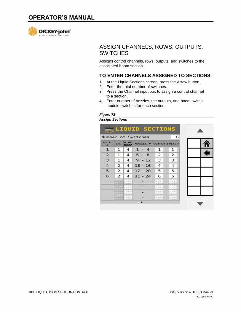
OPERATOR’S MANUAL
108 / LIQUID BOOM SECTION CONTROL ISO6 Version 4 UL 2_3 Manual
6011258 Rev C
ASSIGN CHANNELS, ROWS, OUTPUTS, SWITCHES
Assigns control channels, rows, outputs, and switches to the
associated boom section.
TO ENTER CHANNELS ASSIGNED TO SECTIONS:
1. At the Liquid Sections screen, press the Arrow button.
2. Enter the total number of switches.
3. Press the Channel input box to assign a control channel
to a section.
4. Enter number of nozzles, the outputs, and boom switch
module switches for each section.
Figure 73
Assign Sections
OPERATOR’S MANUAL
ISO6 Version 4 UL 2_3 Manual SECTION LINKING / 109
6011258 Rev C
SECTION LINKING
Section Linking groups sections in a series or in parallel to other
sections in the system so that these ‘linked’ groups turn on or off
simultaneously at the Work Screen.
Sections are commonly used as a channel (swath-by-drive),
individual, or series of rows commanded as a single section
(clutch control).
Subordinate sections turn off when all their assigned master
sections are off at the same time. Subordinates have no control
over the master sections.
TO LINK SECTIONS:
1. Press the SECTION LINKING button.
2. At the Section Linking screen, press the ADD button.
3. Press the Master selection box and select the Master control
type to turn on/off sections as clutch, liquid, channel, or IRC.
4. Press the Subordinate selection box and select the
secondary auxiliary to the Master.
5. Assign each section controlled by the Master to the
appropriate channel.
6. Assign each section of the subordinate module controlled by
the Master.
7. After all sections and channels are linked, press the
Back button.
- The Section Linking screen is now populated with all of
the master/subordinate linkages.
8. Press a specific section linking item and press the EDIT
button to make changes.
9. Press a specific section linking item and press the REMOVE
button to delete a link.
10. Press the Down Arrow button to view additional section
linking items.
IMPORTANT
Refer to the Task Controller screen and/or the Channel
Linking screens for more refined settings that are beyond
the parameters of section linking.

OPERATOR’S MANUAL
110 / SECTION LINKING ISO6 Version 4 UL 2_3 Manual
6011258 Rev C
Figure 74
Linking Sections

OPERATOR’S MANUAL
ISO6 Version 4 UL 2_3 Manual SECTION LINKING EXAMPLES / 111
6011258 Rev C
SECTION LINKING EXAMPLES
Figure 75 depicts 3 typical examples of linking sections:
A) A swath-by-drive with:
Channel 1 master with Channel 4 subordinate
Channel 2 master with Channel 5 subordinate
Channel 3 master with Channel 6 subordinate
The subordinate channels will shut off when the master channels
are commanded off, such as when a task controller is active and
the channels cross over a previously applied area.
B) Six seeding channels of different crops with a common
operation.
Channel/Section 1 - 4 Corn
Channel/Section 5 Fertilizer linked to Channel 1 and 2
Channel/Section 6 Fertilizer linked to Channel 3 and 4
A swath-by-drive example with Channel 5 (Section 5) linked as
subordinate to Channel 1 (Section 1) and Channel 2 (Section 2)
masters and Section 6 subordinate linked to Channel 3 and 4
masters. Section 5 turns off when Channels 1 and 2 are turned
off; Section 6 turns off when Channels 3 and 4 are turned off.
C) 3 Seeding channels and one fertilizer channel.
Channel/Section 4 will remain on unless Channel/Sections
1-3 are all off.
Channel/Section 1 through 3 master sections with Channel 4
as subordinate.
Figure 75
Section Linking Examples

OPERATOR’S MANUAL
112 / GEOMETRY ISO6 Version 4 UL 2_3 Manual
6011258 Rev C
IMPLEMENT GEOMETRY
Physical layout of the implement is required to determine the
position of a channel in the field. Configuring an implement
identifies the hitch type the implement uses, and area the
implement covers. Exact distances are required for physical
layout of the implement. This is important so coverage maps and
section control work properly.
MEASURE X/Y COORDINATES
Stand behind the implement facing the tractor.
X coordinate:
Measure from the hitch pivot point to where the seed is
placed in the ground, e.g. bottom of seed tube, entered as a
negative entry (-X). This measurement should be entered for
each control channel enabled.
Y coordinate:
For each channel determine the center point of the channel.
Use this method:
Find the implement center. This is the point on the
toolbar that is directly behind the hitch.
Determine the distance from the implement center for
the first and last rows or nozzles on the channel.
Calculate the distance from implement center of the
center point of the channel by adding the first and last
row distances and dividing by two.
Distances left of the implement center are entered as
negative numbers (-Y) and to the right are entered as
positive numbers.
For channels that use rows the Y values are
automatically populated, so use the channel center
points to verify the channel setup is correct.
For channels that use nozzles, enter the center point
for reach channel.
Figure 76
32 Row Planter, 3 Point, 2 Control Channels X/Y Coordinate Example

OPERATOR’S MANUAL
ISO6 Version 4 UL 2_3 Manual GEOMETRY / 113
6011258 Rev C
Figure 77
24 Row Planter 1 Control Channel X/Y Coordinate Example
IMPORTANT
It is critical to enter the exact distances required when
setting up the physical layout of the implement position. It
is strongly suggested that a tape measure is used to
ensure exact measurements. Failure to enter accurate
measurements of the implement control channels will
impact the system’s performance to shut row sections off
at the proper location within the field.
Figure 78
Geometry Summary Screen

OPERATOR’S MANUAL
114 / GEOMETRY ISO6 Version 4 UL 2_3 Manual
6011258 Rev C
TO ENTER X/Y COORDINATES:
1. Press the GEOMETRY button.
2. At the Geometry screen, press the GEOMETRY SETUP
button.
- The tractor/implement illustration on the Geometry
screen (Figure 78) is a visual indicator of
channel/implement layout once dimensions are entered
at the Geometry Setup screen.
3. At the Geometry Setup screen, select the implement type
used that matches the equipment.
Figure 79
Select Implement Type
4. At the Geometry Setup screen, enter the X and Y
coordinates for the implement type selected. Measurements
for each implement type defined below.
- Note that -Y is to the left of the hitch, +Y is to the right of
the hitch, -X is further behind the tractor and +X is
towards the tractor with respect to the hitch.
THREE-POINT HITCH TYPE
A) Enter the distance (Y value) from implement center to channel
center left and right. If implement bar is offset from 0, enter the
size of the offset. This value is typically 0.

OPERATOR’S MANUAL
ISO6 Version 4 UL 2_3 Manual GEOMETRY / 115
6011258 Rev C
Figure 80
Three-Point Hitch Dimensions
SEMI-MOUNT AND DRAWBAR HITCH TYPES
A) Enter the distance from the hitch to the pivot point axle
center. On a 2 point implement, the measurement is taken
at the semi-mount single pivot point that is incorporated into
the 2 point mount.
B) Enter the distance (Y value) from implement center to channel
center left and right. If implement bar is offset from 0, enter the
size of the offset. This value is typically 0.
Figure 81
Semi-Mount Implement Type

OPERATOR’S MANUAL
116 / GEOMETRY ISO6 Version 4 UL 2_3 Manual
6011258 Rev C
DOUBLE PIVOT HITCH TYPE
1. Enter the distance from the tractor hitch to cart axle center.
2. Enter the distance from the first cart axle center (directly
behind tractor) to the second cart hitch.
3. Enter the distance from the second cart hitch to the
implement axle center.
4. Enter the distance (Y value) from implement center to
channel center left and right. If implement bar is offset from
0, enter the size of the offset. This value is typically 0.
NOTE
Double Pivot type are typically used with tow between air
carts.
Figure 82
Double Pivot Implement Type
5. Press the Arrow button to display the Channel Preview
screen. A channel’s position identifies the distance
between the implement GPS coordinates and where
seed is dispersed.
- The dashed line represents the X coordinate entered on
the hitch selection screen.
6. The initial Channel Geometry screen displays multiple
channel positions stacked behind one another.
7. Enter the ‘X’ coordinate in inches (centimeters) for the
first channel.
8. Press the Down Arrow button to enter the next channel’s
coordinates. As each channel’s position ‘X’ coordinate is
entered it displays in the new assigned position.
9. Press the DONE button when finished.

OPERATOR’S MANUAL
ISO6 Version 4 UL 2_3 Manual GEOMETRY / 117
6011258 Rev C
IMPORTANT
Verify that all channels align correctly and no channel
overlap occurs. Failure to enter accurate measurements of a
control channel’s position will impact the system’s
performance to shut row sections off at the proper location
within the field.
NOTE
Liquid channels must enter the Y coordinate on the channel
preview setup page if there is more than one channel. Planter
and granular channels cannot edit the Y on the channel
preview screen, and only modify it on the hitch type selection
page.
Figure 83
Enter Control Channel Positions “X” Coordinate

OPERATOR’S MANUAL
118 / SENSOR SETUP ISO6 Version 4 UL 2_3 Manual
6011258 Rev C
SENSOR SETUP
Sensor setup assigns up to 196 sensors to rows, selection of the
row type (population/blockage), and assignment of operations to
a module type. If no rows are configured, population monitoring
cannot occur.
SENSOR CONFIGURATION REQUIREMENTS:
An Operation and its channels must have continuous
row numbers.
A section must have continuous row numbers.
Inputs on a module must start at input 1 and sequence up
a number continuously with no skipped inputs.
A row sensor may not be assigned to more than
one Operation.
If a row has multiple sensors, the sensors on that row cannot
share Operations.
The lowest module address must represent the module
closest to the left side (row 1) of the system. The highest
module address must represent the module closest to the
right side (number of configured rows) of the system.
A module does not have to use all row sensors available
to it.
The operation number assigned to a sensor determines what
is measured. For example, assigning a blockage sensor to
a fertilizer operation or a seed sensor assigned to a
population operation.
Figure 84
Correct Sensor Connections to Module

OPERATOR’S MANUAL
ISO6 Version 4 UL 2_3 Manual SENSOR SETUP / 119
6011258 Rev C
IMPORTANT
If there are gaps in sensor inputs on a module, the
counting of sensors stops and an alarm activates.
Figure 85
Incorrect Sensor Connections to Module
SENSOR SETUP
Sensor Setup assigns sensors to modules and operations.
TO ASSIGN SENSORS:
1. Press the SENSORS button.
2. Press the SETUP button.
3. Enter number of sensors assigned to the module.
4. Enter the row type as population or blockage.
5. Select the name of the operation to assign the sensors to
that operation.
6. Press the ADD button to display a new sensor row input bar
and repeat steps 3 through 5 as needed.
7. If there are row sensors available on more than one module,
press the NEXT MODULE button to display the next Module
screen.
- Press the PREV MODULE button to return to
previous screen.
- Repeat Steps 3 through 6 for each module.

OPERATOR’S MANUAL
120 / SENSOR SETUP ISO6 Version 4 UL 2_3 Manual
6011258 Rev C
Figure 86
Assigning Sensors to ISO6 Module
8. After all sensors are entered, press the Arrow button to
navigate to the next screen.
9. Press the AUTO CONFIG button to auto-assign sensors to
the operations.
- A sensor’s position is indicated in the operation column it
is assigned to with an “X” indicating the sensor is off.
- Sensors may be assigned manually by pressing the icon
in the table corresponding to the row and operation.
10. Press the Checkmark button to begin auto configuration.
- Operation/sensor assignment does not become active
until the sensor is configured to a sensor type.
11. After configuration is complete, sensors and assignments
now display on the Sensors Summary screen as population
or blockage.
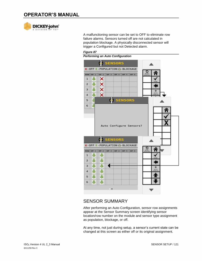
OPERATOR’S MANUAL
ISO6 Version 4 UL 2_3 Manual SENSOR SETUP / 121
6011258 Rev C
A malfunctioning sensor can be set to OFF to eliminate row
failure alarms. Sensors turned off are not calculated in
population blockage. A physically disconnected sensor will
trigger a Configured but not Detected alarm.
Figure 87
Performing an Auto Configuration
SENSOR SUMMARY
After performing an Auto Configuration, sensor row assignments
appear at the Sensor Summary screen identifying sensor
location/row number on the module and sensor type assignment
as population, blockage, or off.
At any time, not just during setup, a sensor’s current state can be
changed at this screen as either off or its original assignment.

OPERATOR’S MANUAL
122 / SENSOR SETUP ISO6 Version 4 UL 2_3 Manual
6011258 Rev C
In certain instances, a user may want to manually adjust a
sensor’s location that has been configured by performing an
Auto Configuration, e.g. when there are fewer sensors than rows
on an operation. A sensor can be turned off for a row and
manually entered at another location.
Also a faulty sensor can be turned off to eliminate
population alarms.
TO ADJUST A SENSOR TYPE:
1. Press the SETUP button.
2. At the Sensor Module Assign screen, scroll using the Up or
Down Arrow buttons to select the appropriate sensor range.
3. Select the desired sensor type of Population or Blockage.
4. Press the Arrow button to navigate to the next page.
5. Perform an Auto Configuration or select the operation row
sensor and select the new sensors type for each sensor.
Figure 88
Edit Sensor Type
SENSOR DETAILS
Sensor Summary displays sensors on a row and their respective
operation assignment. In Summary view, the table displays the
type of sensor configured. The legend in the header displays the
available types.

OPERATOR’S MANUAL
ISO6 Version 4 UL 2_3 Manual SENSOR SETUP / 123
6011258 Rev C
Pressing the DETAILS button displays the module address (red)
and input number (blue). This screen is viewable only.
Figure 89
Sensor Details
SENSOR DETECT
Performing a Sensor Detect checks the system configuration to
verify that sensors configured match the actual number of
sensors connected to a module.
An alarm may trigger if any missing sensors are found or too
many sensors are configured.
If an alarm occurs, verify that the number of sensors at the
Sensor Summary screen matches the actual number of
sensors connected to the appropriate module.
Confirm that all harnessing and sensors are
connected properly.
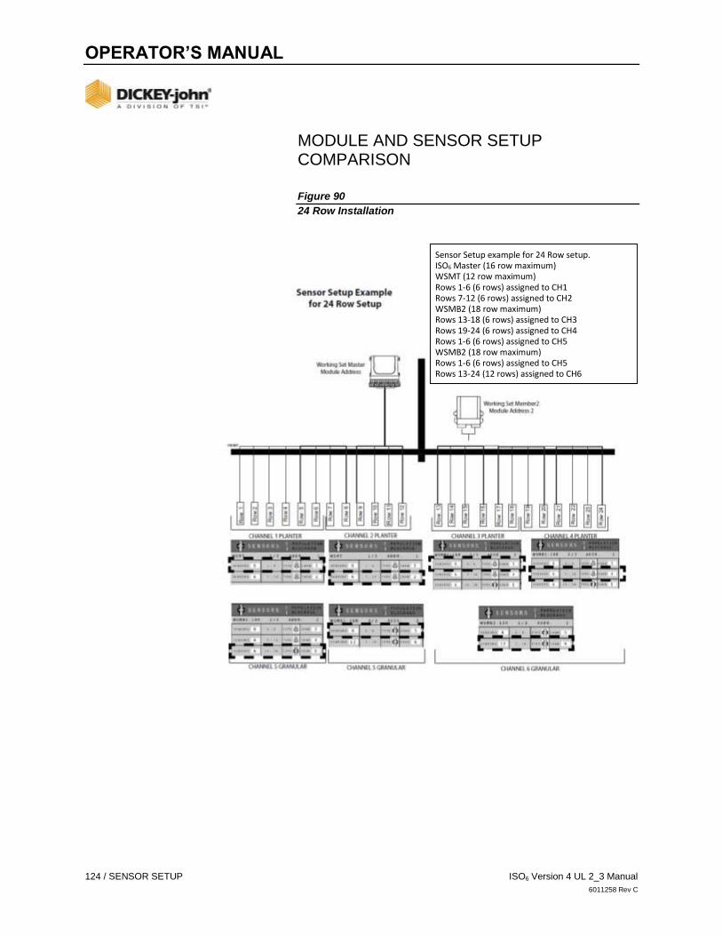
OPERATOR’S MANUAL
124 / SENSOR SETUP ISO6 Version 4 UL 2_3 Manual
6011258 Rev C
MODULE AND SENSOR SETUP COMPARISON
Figure 90
24 Row Installation
Sensor Setup example for 24 Row setup. ISO6 Master (16 row maximum) WSMT (12 row maximum) Rows 1-6 (6 rows) assigned to CH1 Rows 7-12 (6 rows) assigned to CH2 WSMB2 (18 row maximum) Rows 13-18 (6 rows) assigned to CH3 Rows 19-24 (6 rows) assigned to CH4 Rows 1-6 (6 rows) assigned to CH5 WSMB2 (18 row maximum) Rows 1-6 (6 rows) assigned to CH5 Rows 13-24 (12 rows) assigned to CH6

OPERATOR’S MANUAL
ISO6 Version 4 UL 2_3 Manual SENSOR SETUP / 125
6011258 Rev C
Figure 91
48 Row Installation
WSMT (12 row maximum) Rows 1-12 (12 rows) assigned to CH1 WSMB2 (18 row maximum) Rows 13-24 (12 rows) assigned to CH2 Rows 25-30 (6 rows) assigned to CH3 WSMB2 (18 row maximum) Rows 31-36 (6 rows) assigned to CH3 Rows 37-48 (12 rows) assigned to CH4
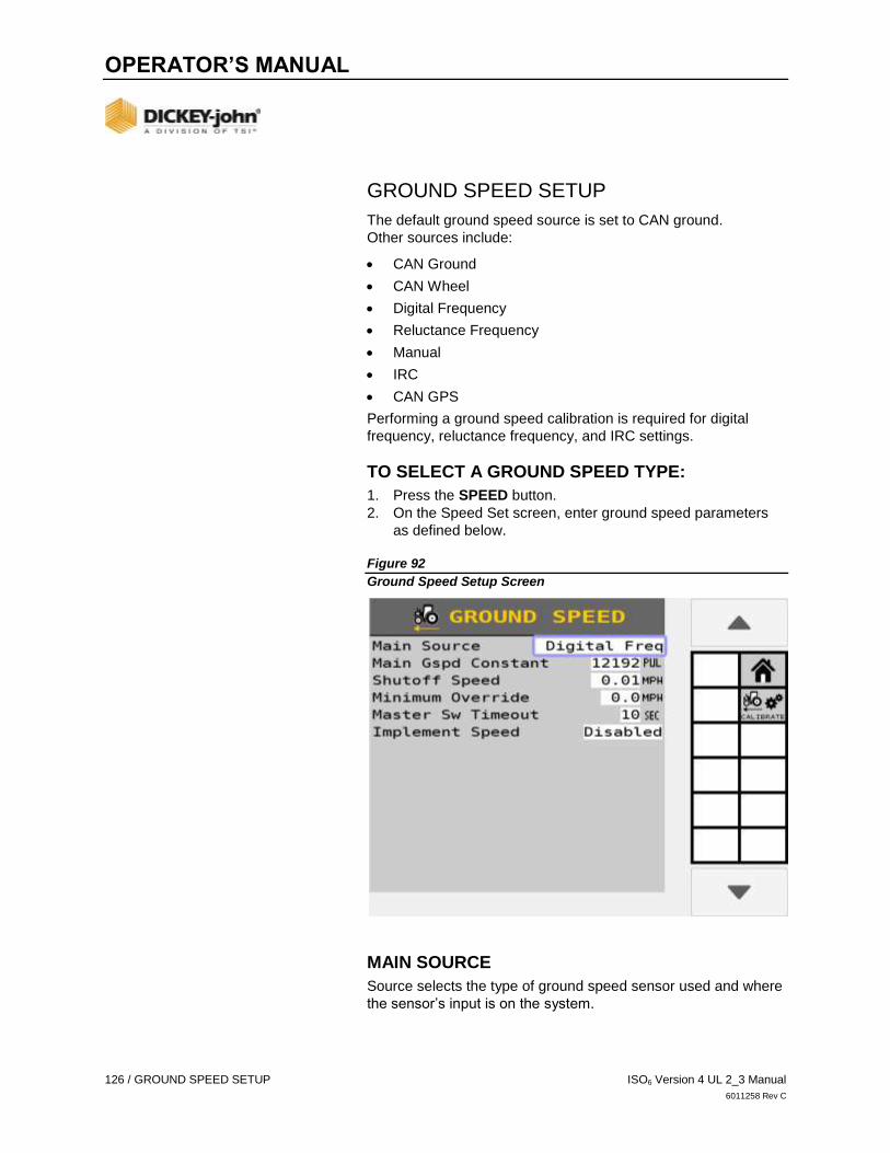
OPERATOR’S MANUAL
126 / GROUND SPEED SETUP ISO6 Version 4 UL 2_3 Manual
6011258 Rev C
GROUND SPEED SETUP
The default ground speed source is set to CAN ground.
Other sources include:
CAN Ground
CAN Wheel
Digital Frequency
Reluctance Frequency
Manual
IRC
CAN GPS
Performing a ground speed calibration is required for digital
frequency, reluctance frequency, and IRC settings.
TO SELECT A GROUND SPEED TYPE:
1. Press the SPEED button.
2. On the Speed Set screen, enter ground speed parameters
as defined below.
Figure 92
Ground Speed Setup Screen
MAIN SOURCE
Source selects the type of ground speed sensor used and where
the sensor’s input is on the system.
OPERATOR’S MANUAL
ISO6 Version 4 UL 2_3 Manual GROUND SPEED SETUP / 127
6011258 Rev C
CAN GROUND
Ground speed is provided by a radar/digital (3-wire) type sensor
connected to the tractor ECU through the cab harness or if
radar/forward ground speed is communicated on the CAN bus.
CAN WHEEL
Wheel speed data is communicated on the CAN bus. This
source does not account for slip-like CAN ground.
RELUCT FREQ
Ground speed is provided by a reluctance (2-wire) type sensor
connected to the actuator harness through an adapter harness.
DIGITAL FREQ
Ground speed is provided by a radar/digital (3-wire) type sensor
connected to the actuator harness.
MANUAL
A MANUAL SPEED button displays on the Work Screen and
sets the system to operate using a constant, internally generated
ground speed and is typically used in the event of a ground
speed sensor failure. This is a constant, internally generated
ground speed that causes the system to operate when the
master switch is ON at the speed that has been programmed.
This value can be set to any speed within the delivery
capabilities of the system.
No ground speed sensor is required when using the
Manual setting.
No area accumulation occurs when speed source is manual.
Implement Lift Override: If enabled the implement lift is not
needed to run.
NOTE
Manual ground speed can only be entered if the source is
changed to MANUAL.
IRC
IRC ground speed is provided by two radar/digital (3-wire) type
sensor connected to the left-most and right-most IRC modules
on the system.
An offset from the center must be provided for each sensor.
CAN GPS
Ground speed is provided by the tractor GPS. Specific PGN
outputs are required for this setting.
GPS must output messages on CAN bus.
The message required for communication is PGN 129026,
NMEA high-precision rapid update.

OPERATOR’S MANUAL
128 / GROUND SPEED SETUP ISO6 Version 4 UL 2_3 Manual
6011258 Rev C
MAIN GROUND SPEED CONSTANT
Represents the pulse count produced by the ground speed
sensor over a 400’ distance. A ground speed calibration is
recommended to obtain the ground speed constant. Refer to the
Calibration section for additional information.
Using a single source radar assumes all rows are moving at the
single speed provided by the tractor speed sensor.
SHUTOFF SPEED
Indicates the minimum ground speed allowed before the system
shuts off all control channels.
MINIMUM OVERRIDE
Minimum override takes over when actual ground speed is below
the designated value. The control operates at this speed until
actual ground speed rises above the minimum override speed or
the actual speed drops below the shutoff speed. The Minimum
Override speed has a background color of black and appears in
the ground speed location on the Work Screen.
NOTE
Minimum override and Master Switch Timeout features will not
display on the Ground Speed setup screen when only Monitor
Type channels are configured.
Figure 93
Minimum Override

OPERATOR’S MANUAL
ISO6 Version 4 UL 2_3 Manual GROUND SPEED SETUP / 129
6011258 Rev C
MASTER SW TIMEOUT
Determines the length of time before the system disables the
operate function after ground speed is 0 (zero) if the master
switch remains in the ON position. After the delay time elapses,
an alarm is issued stating that the master switch must be toggled
OFF/ON before the system will restart.
GROUND FAIL ALARM DELAY
Determines the length of time after the ground speed goes to
zero and seed flow continues before the alarm sounds. This
alarm only applies when Monitor Type control channels are
configured.
IMPLEMENT SPEED
A harness is required for this feature and is an input that is
connected to the sensor that senses the implement speed,
i.e. tone wheel with digital proximity sensor. If enabled, the
frequency detected on this input must be above the frequency
threshold before channels will run. Implement Speed must be
enabled when the MASTER SWITCH button is not used.
GROUND SPEED CALIBRATION
Ground speed is the rate in MPH (Kph) as measured by the
ground speed sensor. The number reflects the number of pulses
generated by the ground speed sensor while traveling a distance
of 400 feet (100 meters).
IMPORTANT
Performing a ground speed calibration directly influences
population, area accumulation, and application rate
control and is required for digital frequency, reluctance
frequency and IRC.

OPERATOR’S MANUAL
130 / GROUND SPEED SETUP ISO6 Version 4 UL 2_3 Manual
6011258 Rev C
Figure 94
Ground Speed Calibration
TO PERFORM A CALIBRATION:
1. Measure a 400 foot (100 meters) course marking start
and finish points.
2. Press the CALIBRATE button to open the
Calibration screen.
3. Drive tractor 2-5 mph and press the START button at the
start of the 400 foot course to begin calibration. The display
showing the ground speed calibration will zero and begin
counting ground speed pulses.
4. Press STOP button at the end of the 400 foot course. The
new calibration number displays on the center of the screen.
5. Enter the average calibration number.
6. Press the SAVE button to save the new calibration.
TIP: For better accuracy, run this course 3 times and average
the 3 calibration numbers. Enter the averaged number at Main
Ground Speed Constant.

OPERATOR’S MANUAL
ISO6 Version 4 UL 2_3 Manual ACCESSORY SENSORS / 131
6011258 Rev C
ACCESSORY SENSORS
ACCESSORY SUMMARY
The Accessory Sensor screen displays the optional sensors
installed i.e. an RPM sensor to monitor shaft/fan speeds or an air
pressure sensor. Supported Accessory sensors include:
Hopper
Pressure
RPM
Digital
The landing page shows currently configured sensors. Pressing
the ACC SETUP button enters setup to configure sensors for
each available ACC module on the system. Pressing the
ACC DIAG button enters the Accessories Diagnostic page which
can be used to test configured Accessory Sensors.
ACCESSORY SETUP
Figure 95
Accessory Summary Screen
The Accessory Setup screen allows accessory sensors to be
configured for each supported accessory module. Pressing the
NEXT MODULE softkey navigates through each supported
accessory module to setup sensors for the selected module.

OPERATOR’S MANUAL
132 / ACCESSORY SENSORS ISO6 Version 4 UL 2_3 Manual
6011258 Rev C
Performing a Sensor Detect checks the system configuration to
verify that sensors configured match the actual number of
sensors connected to a module. Sensor Detect is performed on
all modules. Sensor Detect only detects Pressure and Hopper
accessory sensors.
An alarm may trigger if any missing sensors are found or too
many sensors are configured.
If an alarm occurs, verify that the number of sensors at the
Sensor Summary screen matches the actual number of
sensors connected to the appropriate module.
Confirm that all harnessing and sensors are
connected properly.
Pressing the AUTO CONFIG button performs a Sensor
Detect and automatically configures unassigned sensors.
AUTO CONFIG only works for Pressure and Hopper sensors.
RPM and Digital sensors must be configured manually.
Pressing the ADD button allows adding a sensor for the selected
module. The Add Sensor Type screen shows the number of
currently configured sensors vs. the max number of allowed
sensors for each type on the module.
After a sensor has been added to the selected module, press the
created sensor row to find the REMOVE, COPY and EDIT
softkeys. Pressing REMOVE deletes the sensor from the
module. Pressing COPY will create a new sensor with the same
properties as the highlighted sensor on the selected module as
long as the maximum number of that sensor type has not been
reached for the selected module. Pressing EDIT will enter
the sensor setup screen for that sensor type as seen in
sections below.
Each sensor setup screen is comprised of two pages: the first
page sets up parameters specific to that sensor type and the
second page sets up alarm parameters. The alarm parameters
have a common setup.
Figure 96
Add Accessory
OPERATOR’S MANUAL
ISO6 Version 4 UL 2_3 Manual ACCESSORY SENSORS / 133
6011258 Rev C
ACCESSORY ALARM SETUP
Page 2 of the accessory setup contains common alarm settings.
Each accessory type shares these alarm parameters:
SENSOR NAME
Pressing the Sensor Name field at the top right can change the
desired name for the sensor.
HIGH/LOW ALARM LEVEL
Enter a value for the sensor type at which the high/low warning
alarm alerts an out-of-limits state.
HIGH/LOW ALARM DELAY
Enter a value in seconds that creates a delay between the
detection of a high/low alarm condition and the resulting
alarm display.
HIGH/LOW ALARM GATING
Select where high/low alarms should display:
None: Accessory alarms can appear regardless of the
system state.
In Work: Accessory alarms can only appear in the
Work Screen.
Safety Input Active: Accessory alarms can only appear the
Safety Input is active.
Implement Down In Work: Accessory alarms can only
appear when in the Work Screen with the implement down.
HIGH/LOW ALARM BEHAVIOR
Select how often high/low alarms should display:
No Alarms: Accessory alarms cannot display.
Repeatedly: Accessory alarms can display continuously.
Pressing CANCEL when the alarm comes up will temporarily
disable the alarm until the alarm state is reentered.
Once Per Power Cycle: Accessory alarms can display only
once per power cycle.
Once Per Safety Input: Accessory alarms can display only
once per Safety Input cycle.
Once Per Imp Lift: Accessory alarms can display only once
per implement lift cycle.

OPERATOR’S MANUAL
134 / ACCESSORY SENSORS ISO6 Version 4 UL 2_3 Manual
6011258 Rev C
A combination of the gating and behavior alarms determine
where and how often an alarm will appear. For example, if
Gating is set to None and Behavior is set to Repeatedly, the
alarm will trigger regardless of what screen the user is in and will
continuously happen when the alarm state is re-entered.
PRESSURE SENSOR SETUP
Figure 97
Pressure Sensor Setup Pages 1 and 2
SENSOR NAME
Pressing the Sensor Name field at the top right can change the
desired name for the sensor.
PRESSURE UNITS
Select between millibar, bar, or KPA for the pressure unit.
FREQUENCY AT MIN/MAX PRESSURE
Enter a frequency value for the minimum/maximum pressure
range of the sensor.
MIN/MAX PRESSURE
Enter a pressure value for the minimum/maximum pressure
range of the sensor.
Refer to Accessory Alarm Setup for details on alarm setup for
Pressure Sensors.

OPERATOR’S MANUAL
ISO6 Version 4 UL 2_3 Manual ACCESSORY SENSORS / 135
6011258 Rev C
HOPPER SENSOR SETUP
Figure 98
Hopper Sensor Setup
SENSOR NAME
Pressing the Sensor Name field at the top right can change the
desired name for the sensor.
NOTE
For a Dj Hopper Level sensor, this value should be set to
ACTIVE LO.

OPERATOR’S MANUAL
136 / ACCESSORY SENSORS ISO6 Version 4 UL 2_3 Manual
6011258 Rev C
LOGIC LEVEL
Sets the active state of the sensor and allows flexibility to
connect sensors that have different active outputs. There are two
settings available:
ACTIVE HI - Sets the active state to “High” signifying that an
alarm is generated if the sensor’s output is in a high state.
Use this setting if the connected sensor outputs a high
condition when active.
ACTIVE LO - Sets the active state to “Low” signifying that an
alarm is generated if the sensor’s output is in a low state.
Use this setting if the connected sensor outputs a low
condition when active.
LOGIC LEVEL TABLE
ENSOR LOGIC LEVEL VALUE HOPPER STATUS ALARM
Active High 0 Full Blocked No alarm
Active High 1 Empty Not Blocked Alarm
Active Low 0 Empty Not Blocked Alarm
Active Low 1 Full Blocked No Alarm
Refer to Accessory Alarm Setup for details on alarm setup for
Hopper Sensors.
RPM SENSOR SETUP
IMPORTANT
Performing an Auto Config does not detect installed
RPM sensors.
Figure 99
RPM Setup Screen
SENSOR NAME
Pressing the Sensor Name field at the top right can change the
desired name for the sensor.

OPERATOR’S MANUAL
ISO6 Version 4 UL 2_3 Manual ACCESSORY SENSORS / 137
6011258 Rev C
RPM CONSTANT
Enter the number of pulses per shaft revolution. If the sensor is
mounted directly to the shaft, the value to enter is the number of
pulses generated by the sensor per revolution of the shaft itself.
If the sensor is mounted elsewhere, a gear or sprocket ratio must
be calculated and entered into the RPM constant.
RPM FILTER
Enter a value that filters the signal out of the RPM sensor.
Typically no filtering is required so the standard value is set at
0%. If the RPM readout on the Work Screen is oscillating in
excess of 10%, increasing the filter value will filter the signal to
reduce the oscillation. For a true RPM value this number should
be set to 0%.
DIGITAL SENSOR SETUP
Figure 100
Digital Sensor Setup
SENSOR NAME
Pressing the Sensor Name field at the top right can change the
desired name for the sensor.

OPERATOR’S MANUAL
138 / ACCESSORY SENSORS ISO6 Version 4 UL 2_3 Manual
6011258 Rev C
LOGIC LEVEL
Sets the active state of the sensor and allows flexibility to
connect sensors that have different active outputs. There are two
settings available:
ACTIVE HI - Sets the active state to “high” signifying that an
alarm is generated if the sensor’s output is in a high state.
Use this setting if the connected sensor outputs a high
condition when active.
ACTIVE LO - Sets the active state to “Low” signifying that an
alarm is generated if the sensor’s output is in a low state.
Use this setting if the connected sensor outputs a low
condition when active.
Logic Level Table
SENSOR LOGIC LEVEL VALUE ALARM
Active High 0 No alarm
Active High 1 Alarm
Active Low 0 Alarm
Active Low 1 No Alarm
Refer to Accessory Alarm Setup for details on alarm setup for
Digital Sensors.

OPERATOR’S MANUAL
ISO6 Version 4 UL 2_3 Manual BOUT MARKERS / 139
6011258 Rev C
BOUT MARKERS
BOUT MARKER SETUP
Bout Marker output control can be enabled by selecting Enabled
in the Marker Control Dropdown.
Checking Up for Marker Feedback enables sensors on the left
and right that activate when the respective marker is in the
“Up” position.
Checking Down for Marker Feedback enables sensors on the
left and right that activate when the respective marker is in the
“Down” position.
Table 6. Proximity Sensor States with only Bout Marker Up
Sensors Enabled
NOTE
Because this sensor is detecting the Up condition, if the target
is sensed then the sensed state is Up.
Target Up Sensor State Feedback Sensed State
Not Present LO Down
Present HI Up
Table 7. Proximity Sensor States with only Bout Marker
Down Sensors Enabled
NOTE
Because this sensor is detecting the Down condition, if the
target is sensed then the sensed state is Down.
Target Down Sensor State Feedback Sensed State
Not Present LO Up
Present HI Down
NOTE
Because both an Up and a Down sensor are present, the
cases where both sensors do not detect targets (moving) and
where both sensors do sense targets (error) can be handled. If
only one sensor senses the target then the Sensed State
follows the above cases.

OPERATOR’S MANUAL
140 / BOUT MARKERS ISO6 Version 4 UL 2_3 Manual
6011258 Rev C
Table 8. Proximity Sensor States with Bout Marker Up and Bout Marker
Down Sensors Enabled
Up Target Up Sensor State Down Target Down Sensor State Feedback Sensed State
Not Present LO Not Present LO Moving
Not Present LO Present HI Down
Present HI Not Present LO Up
Present HI Present HI Error
Figure 101
Marker Setup Screen

OPERATOR’S MANUAL
ISO6 Version 4 UL 2_3 Manual CUSTOMIZING THE WORK SCREEN / 141
6011258 Rev C
CUSTOMIZING THE WORK SCREEN
The Instruments screen allows customization of how the Work
Screen appears during operation. Two default screens display
the most commonly used instruments but can be changed as
desired. A total of 4 Work Screens are possible.
Page 1 and 2 defaults include:
Product Levels
Area
3 Seeding instruments
Accessories
Materials
Population (bar graphs)
4 Singulate instruments
Quality (bar graphs)
Figure 102
Work Screen Defaults

OPERATOR’S MANUAL
142 / CUSTOMIZING THE WORK SCREEN ISO6 Version 4 UL 2_3 Manual
6011258 Rev C
MODIFYING THE INSTRUMENT LAYOUT
The Work Screen layout is divided into 20 cells. Some
instruments cover more than one cell depending on the size and
orientation selected for the instrument. The choice is selected at
the individual instrument setup screens. Up to 4 works screens
can be set up at 1 time.
Figure 103
Possible Work Screen Instrument Sizes

OPERATOR’S MANUAL
ISO6 Version 4 UL 2_3 Manual CUSTOMIZING THE WORK SCREEN / 143
6011258 Rev C
SELECTING AN INSTRUMENT
Instruments are the selectable parameters that appear on the
Work Screen that monitor control channels, rate targets,
individual row performance, spacing, population, ground speed,
and coverage area during operation.
Instruments can be selected and placed in any position.
Instruments can be changed at any time through the
Instruments screen.
Any instrument can be placed in any position.
Certain types of instruments allow duplicate instruments to
be configured on a single display if desired.
Up to four display screens are configurable.
Existing instruments may limit the size of the neighboring
instruments.
Instrument size and orientation are selected at the individual
Instrument Setup screens.
The size/orientation option will not be selectable if the larger
data item selection will not fit on the Work Screen page.
TO SELECT INSTRUMENTS:
1. Press the INSTRUMENTS button.
2. Select one of the cells.
3. If an existing instrument with options is selected, hit EDIT to
change the Instrument properties or CLEAR to remove the
Instrument. If the cell is blank, hit the ADD softkey to add a
new Instrument.
4. At the Display Type screen, press a button to select one of
the 16 main heading types. Depending on the system
configuration, there may be a second page of
instrument options.
5. Select the desired data item type and size. Refer to
Instruments. Defined section below for definitions. Some
instrument types do not require selecting further options.
6. Press the DONE key to accept selection.
- Press the CLEAR key to remove selected data item.
- Press the Arrow key to create a second Work Screen
(up to 4 Work Screens).

OPERATOR’S MANUAL
144 / CUSTOMIZING THE WORK SCREEN ISO6 Version 4 UL 2_3 Manual
6011258 Rev C
Figure 104
Adding an Instrument

OPERATOR’S MANUAL
ISO6 Version 4 UL 2_3 Manual CUSTOMIZING THE WORK SCREEN / 145
6011258 Rev C
INSTRUMENTS WITHOUT SETUP DEFINED
Several instruments may be added to the work screens without
set up. They include the following:
Marker (1x1 only)
Task Controller (1x1 only)
MARKER INSTRUMENT
This instrument displays the current position of the markers.
Displays when the markers are up, down, moving, or in an
error state.
TASK CONTROLLER INSTRUMENT
This instrument indicates the active status of the task controller.
INSTRUMENTS WITH SETUP DEFINED
SEEDING INSTRUMENT
Displays row number (R1 is row 1 in Figure 106) with the
min/max/average of the selected instrument; Population
(KSeeds/AC or KSeeds/HA), Spacing (Inch/Seed or MM/ Seed)
and Distance (Seeds/Ft or Seeds/M).
Figure 105
Seeding Instrument Setup

OPERATOR’S MANUAL
146 / CUSTOMIZING THE WORK SCREEN ISO6 Version 4 UL 2_3 Manual
6011258 Rev C
Figure 106
Seeding Instrument Defined (Work Screen)
Figure 107
Seeding Instrument Info Page
Figure 108
Singulate Instrument Setup

OPERATOR’S MANUAL
ISO6 Version 4 UL 2_3 Manual CUSTOMIZING THE WORK SCREEN / 147
6011258 Rev C
SINGULATION INSTRUMENT
Seed singulation maximum is 196 rows of seed input.
% Singulation
Singulation refers to the portion of seeds planted individually
rather than in groups. This instrument displays the average
percent seed singulation of the planter’s rows that are configured
for population in large bold font. Additional information includes
the worst four performing rows.
% Multiples
This instrument displays the average percent of multiple seeds
dropped within each row in one location in large bold font. Also
displays the worst 4 performing rows.
% Quality
This instrument displays the average percent spacing quality
across the planter rows against all planter rows in large bold font.
The rows will only have quality data if they are configured on
the ISO6 module with the Advanced Seed Data feature or
on a WSMB2 module. The instrument lists the worst 4
performing rows.
% Skips
This instrument displays the average percent of seeding skips in
rows with quality data against all planter rows in large bold font.
The rows will only have quality data if they are configured on the
ISO6 module with the Advanced Seed Data feature or on a
WSMB2 module. The instrument lists the worst 4
performing rows.
Figure 109
Singulate Instrument Info Page
POPULATION BAR GRAPH INSTRUMENT
This instrument displays population status by row and allows
customization of the rows that are monitored and displayed on
the Work Mode screen. Multiple bar graphs can be added with
different settings per bar graph.

OPERATOR’S MANUAL
148 / CUSTOMIZING THE WORK SCREEN ISO6 Version 4 UL 2_3 Manual
6011258 Rev C
Width
This instrument selects the graphic size of the bar graphs as
either narrow, medium, or wide. The wider bar graphs may
not all appear on the first screen if a larger number of rows
are monitored.
2x1 (fits 6 wide rows, 12 medium rows, or 24 narrow rows) and
4x1 (fits 12 wide rows, 24 medium rows or 48 narrow rows).
Row Scan
This instruments scans through rows at a fast or slow rate. After
the last row displays, the scan rows will re-sequence beginning
with the first active row.
Operations
This instrument selects the operations to monitor on the
Work Screen.
IMPORTANT
Operations must be selected at this screen to become active
on the Work Screen.
Figure 110
Population Bar Graph Setup

OPERATOR’S MANUAL
ISO6 Version 4 UL 2_3 Manual CUSTOMIZING THE WORK SCREEN / 149
6011258 Rev C
QUALITY BAR GRAPH INSTRUMENT
This instrument displays the amount of spacing between each
seed while planting that provides a comparison of row-to-row
meter performance. Ideal conditions are equal spacing between
each seed (100%). As spacing becomes less uniform and more
random, the spacing quality percentage decreases and falls
below 100%. Multiple Quality bar graphs instruments can be
added with different settings per bar graph.
Seed shape, meter type, meter settings, seeding rate, seed bed
preparation and vehicle speed are all factors that can affect
overall spacing quality.
Width
This instrument selects the width of the bar graphs as either
narrow or medium. The wider bar graphs may not all appear on
the first screen if a larger number of rows are monitored. 2x1 (fits
6 wide rows, 12 medium rows, or 24 narrow rows) and 4x1 (fits
12 wide rows, 24 medium rows or 48 narrow rows).
Row Scan
This instrument scans through rows at a fast or slow rate. After
the last row displays, the scan rows will re-sequence beginning
with the first active row.
Operations
This instrument selects the operations to monitor on the
Work Screen.
Spacing Variance
This instrument sets the user-defined percentage to set the bar
graph range for spacing quality. The bottom of the bargraph will
correspond to the user set Spacing Variance subtracted from
100%. A spacing variance of 10% will result in graphs that show
quality levels that range from 90% to 100%.
Bar Graph Size
This instrument sets the bar graph size as 2x1 or 4x1 column.
Row Scan
This instrument scans through rows at a fast or slow rate. After
the last row displays, the scan rows will re-sequence beginning
with the first active row.
Operations
This instrument selects the operations to monitor on the
Work Screen.

OPERATOR’S MANUAL
150 / CUSTOMIZING THE WORK SCREEN ISO6 Version 4 UL 2_3 Manual
6011258 Rev C
Spacing Variance
This instrument sets the user-defined percentage to set the bar
graph range for spacing quality. The bottom of the bar graph will
correspond to the user set Spacing Variance subtracted from
100%. A spacing variance of 10% will result in graphs that show
quality levels that range from 90% to 100%.
Bar Graph Size
This instrument sets the bar graph size as 2x1 or 4x1 column.
Row Scan
This instrument scans through rows at a fast or slow rate. After
the last row displays, the scan rows will re-sequence beginning
with the first active row.
Operations
This instrument selects the operations to monitor on the
Work Screen.
Spacing Variance
This instrument sets the user-defined percentage to set the bar
graph range for spacing quality. The bottom of the bar graph will
correspond to the user set Spacing Variance subtracted from
100%. A spacing variance of 10% will result in graphs that show
quality levels that range from 90% to 100%.
Bar Graph Size
This instrument sets the bar graph size as 2x1 or 4x1 column.

OPERATOR’S MANUAL
ISO6 Version 4 UL 2_3 Manual CUSTOMIZING THE WORK SCREEN / 151
6011258 Rev C
Figure 111
Spacing Quality Bar Graph Setup
Figure 112
Spacing Quality Bar Graph Defined
AREA INSTRUMENT
Area Per Hour
This instrument displays the current area per hour of the planter
in acres (AC) or hectares (HA). The value is continuously
calculated based on the current ground speed and
implement width.
Channel Scan
When active, this instrument scans through active channels
displaying the total acreage covered by a specific channel.
Channel Area
This instrument displays the area covered by control channels
1-8. Area is calculated using the channel width parameter. Area
accumulates when the master switch is ON and the ground
speed is above the shutoff speed. This accumulator is resettable
to 0.0 through the Field Reset key on the Area Info screen or the
Totals screen. Current area is retained after power down.

OPERATOR’S MANUAL
152 / CUSTOMIZING THE WORK SCREEN ISO6 Version 4 UL 2_3 Manual
6011258 Rev C
Selecting a channel type, e.g. Channel 1 Area, displays area
totals specific to that channel.
Material Type Area
This instrument displays 6 material types for a total area: Planter,
Granular Seed, Granular Fertilizer, Liquid Fertilizer, Granular
Crop Protect, and Liquid Crop Protect.
To display total area of all channels on a particular material type,
the product class must be defined at the Material setup screen.
When the product class is defined for current channels, this
choice appears on the Material Instrument screen (Figure 115).
NOTE
Area Totals for a specific field is selected at the Totals screen.
IMPORTANT
Items must be selected at this screen to become active on
the Work Screen.
IMPORTANT
An accumulator reset is completed for an entire field.
Resetting area to zero for an individual item is not
possible.
Figure 113
Area Instrument Setup

OPERATOR’S MANUAL
ISO6 Version 4 UL 2_3 Manual CUSTOMIZING THE WORK SCREEN / 153
6011258 Rev C
CONTROL INSTRUMENT
1. Select the instrument size (‘small’ covers 1x1 and ‘large’
covers 2x2 cells).
2. Select the channel number and the instrument to appear on
the Work Screen.
3. Select the Rate Display Type:
- Area - Displays actual application rate values for the
desired channel with the target rate value in black. Both
rates appear in black within target parameters and red
when outside of parameter limits. Only available for
channel types that cover an area.
- RPM - Displays the actual RPM of the channel. This
option is available for fan and shaft channels. Both target
RPM and actual RPM appear in black when controlling
within target parameters and actual RPM displays in red
when outside of parameter limits.
- Time - Displays actual seeds per second values for the
desired channel with the application target rate value in
black. Only available for channels that have a per-time
rate.
- None - Displays only the target application rate value in
black. Does not display an actual rate
4. Select the Sensitivity of the arched gauge:
- Fine - the arched gauge will display green when the
actual rate is +/- 3% of the target rate, yellow when >3%
and <= 10% error from target, and red when >10% and
<12.9% error. When greater than 12.9% error, the gauge
will display as red with the indicator dot remaining at
the edge.
- Medium - the arched gauge will display green when the
actual rate is +/- 5% of the target rate, yellow when >5%
and <= 10% error from target, and red when >10% and
<12.9% error. When greater than 12.9% error, the gauge
will display as red with the indicator dot remaining at
the edge.
- Coarse - the arched gauge will display green when the
actual rate is +/- 8% of the target rate, yellow when >8%
and <= 10% error from target, and red when >10% and
<12.9% error. When greater than 12.9% error, the gauge
will display as red with the indicator dot remaining at
the edge.

OPERATOR’S MANUAL
154 / CUSTOMIZING THE WORK SCREEN ISO6 Version 4 UL 2_3 Manual
6011258 Rev C
Figure 114
Control Instrument Setup
MATERIALS INSTRUMENT
This instrument displays accumulating material totals for
distance and seed counts by field. The specific field totals that
displays as an Instrument data item is set at the Totals screen.
Total Seeds Applied
This instrument counts pulses for all seed sensors set to
population. Also displays total number of seeds planted.
Channel 1- 8 Seeds
This instrument displays the area covered by control channels
1-8. Material distributed accumulates when the master switch is
ON and the ground speed is above the shutoff speed. Current
material distributed is retained after power down.
Channel Scan
This instrument cycles through active control channels every few
seconds displaying material counts.
Material Type
This instrument displays total material distributed by material
type that encompasses all channels with the same material type,
the product class must be defined at the Material Setup screen.
When the product class is defined, this choice appears on the
Material Instrument screen.
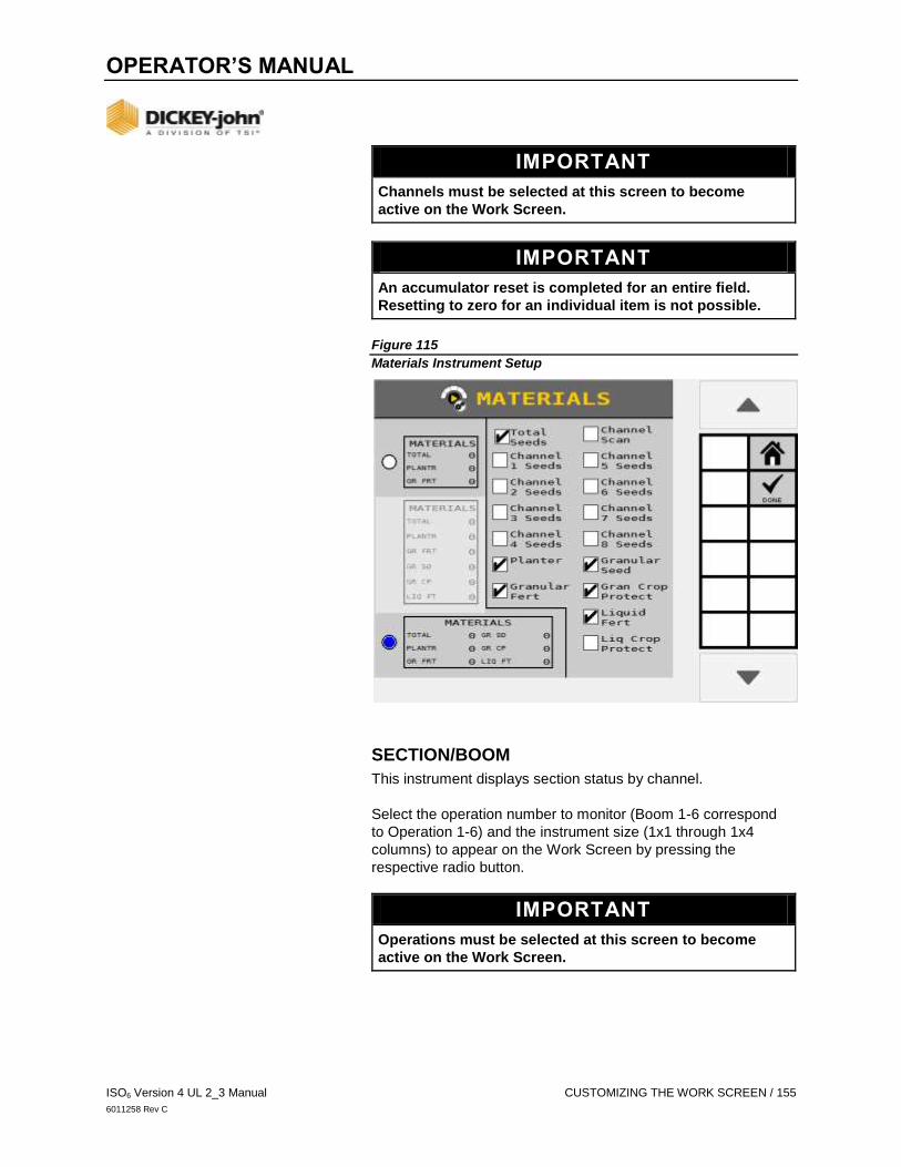
OPERATOR’S MANUAL
ISO6 Version 4 UL 2_3 Manual CUSTOMIZING THE WORK SCREEN / 155
6011258 Rev C
IMPORTANT
Channels must be selected at this screen to become
active on the Work Screen.
IMPORTANT
An accumulator reset is completed for an entire field.
Resetting to zero for an individual item is not possible.
Figure 115
Materials Instrument Setup
SECTION/BOOM
This instrument displays section status by channel.
Select the operation number to monitor (Boom 1-6 correspond
to Operation 1-6) and the instrument size (1x1 through 1x4
columns) to appear on the Work Screen by pressing the
respective radio button.
IMPORTANT
Operations must be selected at this screen to become
active on the Work Screen.

OPERATOR’S MANUAL
156 / CUSTOMIZING THE WORK SCREEN ISO6 Version 4 UL 2_3 Manual
6011258 Rev C
Figure 116
Section/Booms
PRODUCT LEVELS
This instrument displays how much product remains in the
hopper or tank for the channels selected. All eight channels
are selectable.
Product level remaining is tracked by material.
Channel Number
Select the channel number (Channel 1 Level - Channel 8 Level)
and the instrument size to appear on the Work Screen (1x1
through 1x2 columns) by pressing the respective radio button.
Display Value
Select the value to display on the instrument:
Material Name - displays the name of the material assigned
to the channel.
Product Remaining - displays how much material is
remaining of the Material assigned to the channel.
Area Remaining - displays an estimate of how much area
the channel will cover before the channel’s material runs out.
This is based off of Material level, application rate, and
active channel width.

OPERATOR’S MANUAL
ISO6 Version 4 UL 2_3 Manual CUSTOMIZING THE WORK SCREEN / 157
6011258 Rev C
Figure 117
Product Levels Instrument Setup
ACCESSORIES
This instrument displays the status of pressure, RPM, hopper,
and digital sensors.
TO ADD AN ACCESSORY TO BE DISPLAYED ON THE INSTRUMENT:
1. Select a slot on the instrument to edit. A selected slot will be
outlined, and the EDIT key will appear.
2. Press the EDIT key.
3. Select the accessory type from the drop down list.
4. Select the Module Address of the accessory from the drop
down list.
5. Select the Name assigned to the accessory.
6. Press the RETURN key to return to the Accessory
Instrument Setup main page.

OPERATOR’S MANUAL
158 / CUSTOMIZING THE WORK SCREEN ISO6 Version 4 UL 2_3 Manual
6011258 Rev C
Figure 118
Accessories Instrument Setup

OPERATOR’S MANUAL
ISO6 Version 4 UL 2_3 Manual OPERATION / 159
6011258 Rev C
OPERATION
PERFORMING A FILL DISK
Fill Disk fills the seed meters after a material variety change or
after power up on air-actuated planters with seed to allow instant
seed flow when the control is turned on.
The FILL DISK button allows the seed meter to make one
revolution.
FILL DISK FOR PLANTER/GRANULAR SEEDING CHANNELS
The FILL DISK button at the Work Screen runs the selected
channel.
1. At the Work Screen, highlight the appropriate channel.
2. Press the NEXT PAGE button to display the FILL DISK
button.
3. Press the FILL DISK button.
4. Raise the implement.
5. With brakes locked and transmission in the park position,
start the engine.
6. Engage hydraulics and run engine at normal speed until
hydraulic fluid is at operating temperature.
7. Press the START button. The seed meters will turn for 1
revolution, then stop.
8. Pressing the STOP button will also terminate the test.
NOTE
Refer to the System Tests section for using a remote test
switch during a fill disk operation.
CAUTION
Implement will begin to operate after pressing the Start
button. Ensure that all persons and objects are away from
the implement to avoid personal injury.

OPERATOR’S MANUAL
160 / OPERATION ISO6 Version 4 UL 2_3 Manual
6011258 Rev C
Figure 119
Fill Disk Screen for Control Channels
BEGIN OPERATION
START
1. Lower the implement to operating position, engaging the
implement switch, if present and enabled.
2. Ensure the system is engaged with the hydraulic system
engaged and the tractor at its normal operating RPM.
3. Set the master/control switch to the ON position or press the
START MASTER button. All enabled control channels will
begin controlling at the current ground speed. All
accumulators will begin recording data.
WARNING
When the implement is down and the safety input is active
(master switch in the ON position or secondary speed
above threshold), the machine is fully operational. All
necessary precautions must be taken to ensure user
safety. Failure to practice all necessary caution may result
in serious injury or death.

OPERATOR’S MANUAL
ISO6 Version 4 UL 2_3 Manual OPERATION / 161
6011258 Rev C
Figure 120
Work Mode Start Master Switch On
STOP
1. Set the master/control switch to the OFF position or press
the STOP MASTER button. All control channels cease
operation and all data accumulation halts.
2. Operation immediately stops when the ground speed is 0 or
the implement is raised to disengage.
SCROLL WORK MODE SCREENS
Users have the ability to scroll between multiple work screens
during operation. A total of four Work Mode screens are
accessible during operation if four screens are setup.
TO CHANGE WORK SCREEN VIEW:
At the Work Mode screen, press the Right Arrow button.
Continue to press this button to advance to the next screen.
Figure 121
Toggle Work Screens

OPERATOR’S MANUAL
162 / OPERATION ISO6 Version 4 UL 2_3 Manual
6011258 Rev C
WORK SCREEN FUNCTIONS
The Work Screen in Work Mode displays the various instruments
that were selected at the Instruments screen. A total of four
Work Screens are accessible during Work Mode if four
screens are setup.
In Work Mode, buttons appear on the right side of the screen
based on the main instruments selected on the Instruments
screen. (Virtual terminals may vary on button locations) (Figure
122) shows channel 1 control instrument selected. All buttons on
the right side of the screen affect channel 1. When another
instrument is selected, these buttons are replaced with the
buttons relative to the newly selected instrument.
Figure 122
Selecting Channel 1 Instrument
READING THE CONTROL INSTRUMENT
The status ball represents the actual applied rate of material.
The arched status bar contains 5 sections. The middle
section is the ideal applied rate/target rate (Green). Section
percent ranges vary depending on instrument set up. See
Control Instrument Setup for more information.
The rates to the left of the ideal range are under applying
rates below the target limit parameters.
The rates to the right of the ideal range are over applying
rates above the target limit parameters.
The target rate displays as a constant value. Application
rates appear in black within target rate range. Rate values
appear in red when outside of target rate limit parameters.

OPERATOR’S MANUAL
ISO6 Version 4 UL 2_3 Manual OPERATION / 163
6011258 Rev C
Figure 123
Reading the Control Channel
CONTROL CHANNEL ADJUSTMENT
Control channels can be adjusted in Work Mode by selecting
the channel on screen (Figure 122). A channel can be adjusted
as follows:
Active channel can be set to ON or OFF by selecting the
On/Off Channel button.
Target rates can be adjusted by using the Inc/Dec buttons
and the RESET Target button.
INCREMENT
Increases the active channel’s target rate by the amount
specified in the Inc/Dec % or rate table setup for that material.
Increment can be pressed several times to increase the target
rate by the specified amount for every actuation, until the
maximum rate value or preset value is reached. The active
channel/material is displayed in the button text.
DECREMENT
Decreases the active channel’s target rate by the amount
specified in the Inc/Dec % or rate table setup for that material.
Decrement can be pressed several times to reduce the target
rate by the specified amount for every actuation, until the
minimum rate value or preset value is reached. The active
channel/material is displayed in the button text.
INC/DEC RESET TO TARGET
Returns the active channel to the original material target rate.
This button is only available for channels that are active and
have had the target rate adjusted using the Increment or
Decrement buttons in Inc/Dec % mode.

OPERATOR’S MANUAL
164 / OPERATION ISO6 Version 4 UL 2_3 Manual
6011258 Rev C
CONTROL ON/OFF CHANNEL
The active channel can be turned either ON or OFF by pressing
this button. Channels that are set to OFF will not operate when
the master/ control switch is set to the ON position. Turning a
channel OFF is not the same as disabling a channel in Channel
Setup mode. The active channel is displayed in the button text. If
the button text is OFF, this is the action that occurs when the
button is pressed.
OPERATE SCREEN SYMBOLS
IMPLEMENT LIFT SWITCH
The Work Screen identifies the implement position as up or
down. The implement lift switch automatically turns the control
channels on and off without turning the master/control switch off.
The Implement Lift Indicator must be in the down position for the
control channels to operate.
Refer to the Implement Lift Sensor instructions for installation
location.
ROW INDICATORS
Row Indicators in the bar graph area of the Work Screen indicate
seed rate for each row. The size of the bar graphic is
automatically proportional to the screen size. The following
symbols illuminate in the bar graph area:
Figure 124
Row Indicator Symbols

OPERATOR’S MANUAL
ISO6 Version 4 UL 2_3 Manual OPERATION / 165
6011258 Rev C
TASK CONTROLLER ICON
A Task Controller icon displays on control instruments during
operation to indicate that the task controller function is actively
running. The color reflects the current task controller state:
Red – Task Controller is disconnected.
Green – Task Controller is connected and applying at the set
applied rate.
Gray – Task Controller is connected and not
commanding rate.
Yellow – Task Controller is connected and is being
overridden by Manual Rate Override.
Figure 125
Task Controller
WORK MODE INFORMATION SCREENS
Each instrument on the Work Screen has an associated
information screen that provides specific details relating to
that item.
Some values can be reset to zero from these Information
screens or reset to zero when the master switch is off. Once
an accumulator has reached its maximum value, it will roll
over to zero.

OPERATOR’S MANUAL
166 / TASK CONTROLLER ISO6 Version 4 UL 2_3 Manual
6011258 Rev C
TO VIEW WORK MODE INFORMATION SCREENS:
1. At the Work Screen, press the Instrument box to highlight.
Refer to Figure 126.
2. The associated INFORMATION button appears in the right
side bar. Press the INFORMATION button to open.
CONTROL CHANNEL
The Control Information screen provides data for the selected
channel for feedback sensors, valve output, and system voltages
of the ISO6 module.
This data with descriptions are also found at the Diagnostics
screen.
Figure 126
Control Information Screen
SEEDING
The Seeding Information screen provides population, spacing,
and distance data with maximum and minimum values by row as
well as the overall average data.
POPULATION:
Seeding row with the minimum and maximum population in
thousands of seeds per acre (KSeeds/AC) or thousands of
seeds per hectare (KSeeds/HA).
Average population in thousands of seeds per acre
((KSeeds/AC) or thousands of seeds per hectare
(KSeeds/HA)).
SPACING:
Seeding row with the minimum and maximum spacing
in inches.
Average spacing in inches per seed (Inch/Seed) or
millimeters per seed (MM/Seed) of all active seeding rows.

OPERATOR’S MANUAL
ISO6 Version 4 UL 2_3 Manual TASK CONTROLLER / 167
6011258 Rev C
DISTANCE:
Seeding row with the minimum and maximum number of
seeds per foot (Seeds/Ft) or seeds per meter (Seeds/M).
Average distance displays the average number of seeds
per foot (Seeds/Ft) or seeds per meter (Seeds/M) of all
active seeding rows.
Figure 127
Seeding Information Screen
MATERIALS
Provides material totals by a single channel as well as material
totals for all similar channels. Material totals are retained after
power down. Material reset is completed by pressing the
FIELD RESET button.
Figure 128
Materials Instrument Info Page
SEED COUNT
A seed count is performed from the Materials Information screen.
TO USE THE SEED COUNT FUNCTION:
1. Press the SEED COUNT button.

OPERATOR’S MANUAL
168 / TASK CONTROLLER ISO6 Version 4 UL 2_3 Manual
6011258 Rev C
2. At the SEED COUNT screen, press the START button.
Seed count data for each sensor accumulates when seed
drops through the sensor.
- Press the DOWN button to view additional rows.
3. Press the STOP button to stop counting seeds.
Figure 129
Seed Count
POPULATION
Population Information screen displays complete population data
on one screen for a specific row. Highlight the row input box to
change to another row or press the NEXT ROW button to view
data for the next row.
Data specifics for a row include Population, Spacing,
and Distance.
Figure 130
Population Bar Graph Info Page
Next Row
Advances to the next row and relevant data.
Previous Row
Advances to the previous row and relevant data.

OPERATOR’S MANUAL
ISO6 Version 4 UL 2_3 Manual TASK CONTROLLER / 169
6011258 Rev C
Max Row Population
Displays the row producing the highest population.
Min Row Population
Displays the row producing the lowest population.
Row Scan
Starts and stops cycling through all active rows and their
respective data.
AREA
Provides area totals by a single channel as well as area totals
for all similar channels. Area totals are retained after power
down. Area total reset is completed by pressing the
FIELD RESET button. Per Hour displays acres covered
per hour and is not re-settable.
Figure 131
Area Instrument Info Page
BOOM
Booms indicate the status of each boom section and is only
operational with liquid control channels when a DICKEY-john
boom switch module and boom output module are installed for
boom control. The boom status is indicated in Green, Red,
or White.
Green - Section is on.
Red - Section is off by manual switch.
White - Section is off by task controller.
The boom channel (example below BOOM 1) indicates the
active channel.

OPERATOR’S MANUAL
170 / TASK CONTROLLER ISO6 Version 4 UL 2_3 Manual
6011258 Rev C
Figure 132
Boom Instrument Info Page
ACCESSORIES
PRESSURE
Actual pressure measured in oz/in2 (kPa) displays for installed
pressure sensors.
RPM
Actual RPM for active shaft/fan sensors displays for installed
RPM sensors. HOPPER Empty or nonempty status displays for
installed hopper sensors.
DIGITAL
Active (Check) or Inactive (X) status displays for installed
digital sensors.

OPERATOR’S MANUAL
ISO6 Version 4 UL 2_3 Manual TASK CONTROLLER / 171
6011258 Rev C
Figure 133
Accessories Instrument Info Page
SEED SINGULATION AND SPACING QUALITY
% SINGULATE
An average singulation percentage displays in the % Singulate
column. The average percent seed singulation of the planter
rows are configured using an ISO6 module or a WSMB2 module
against all planter rows.
% MULTIPLES
A seed multiples average displays in the % Multiples column;
which is the average percent of multiple seeds dropped in one
location across the planter.

OPERATOR’S MANUAL
172 / TASK CONTROLLER ISO6 Version 4 UL 2_3 Manual
6011258 Rev C
% QUALITY
Displays the average percent spacing of quality across the
planter rows in the % Quality column.
% SKIPS
Displays the average percent of seeding skips across the planter
in the % Skips column.
Figure 134
Seed Singulation and Spacing Quality
QUALITY
Quality bar graph information screen displays complete data
on one screen for a specific row. Highlight the row input to
change to another row or press the Next Row button to view
the next row.
Data specifics for a row include Singulation %, Quality %,
Skips %, and Multiples %.
IMPORTANT
Singulation, Quality, Skips, and Multiple % is only
calculated for the rows connected to a WSMB2 module or
an ISO6. Any rows connected to a WSMB module will NOT
be included in this calculation.

OPERATOR’S MANUAL
ISO6 Version 4 UL 2_3 Manual TASK CONTROLLER / 173
6011258 Rev C
Figure 135
Quality Instrument Info Page
Next Row
Advances to the next row and relevant data.
Previous Row
Advances to the previous row and relevant data.
Max Row Population
Displays the row producing the highest population.
Min Row Population
Displays the row producing the lowest population.
Row Scan
Starts and stops cycling through all active rows and their
respective data.

OPERATOR’S MANUAL
174 / TASK CONTROLLER ISO6 Version 4 UL 2_3 Manual
6011258 Rev C
PRODUCT LEVELS
Channel product levels indicate how much product remains in
the hopper or tank. Product Levels are tracked according to
material. Each material is assumed to have only one tank. The
instrument displays the amount of product remaining of the
material for that channel. The Info page allows the user to reset
or add product to the level of the material. Multiple channels that
share the same material will share the same product level. The
RESET TO CAPACITY button allows you to reset a material to a
specified maximum capacity. The ADD PRODUCT button allows
you to add a specified amount to what is still remaining in your
hopper for that material.
Figure 136
Product Levels Instrument Info Page
MARKERS
Indicates the state of left and right markers and displays a
moving or error condition. The Markers Instrument does not have
an info page.
Marker State
See Marker Setup for more information on possible states. The
Instrument shows the following marker states for both left and
right markers:
Arm/Marker Up: Marker sensed up.
Arm/Marker Down: Marker sensed down.
Yellow overlay: Marker sensed moving (both Up and Down
sensed target not present).
Red overlay: Marker sensed error (both Up and Down
sensed target present).
Toggle
Lifts the marker that is down, and lowers the marker that is up.

OPERATOR’S MANUAL
ISO6 Version 4 UL 2_3 Manual TASK CONTROLLER / 175
6011258 Rev C
Left Up/Down
Left Up will raise the left marker. Left Down will lower the
left marker.
Right Up/Down
Right Up will raise the right marker. Right Down will lower the
right marker.
Figure 137
Marker Instrument
TASK CONTROLLER
Indicates Task Controller status as connected (Check),
disconnected (X), and displays the override (SC OVERRIDE)
if active.
SECTION CONTROL OVERRIDE BUTTON
Press the SECTION CONTROL OVERRIDE button to ignore
task controller state commands. This function is useful when
planting over an area that is already planted and prevents a
reset of the task controller map.

OPERATOR’S MANUAL
176 / TASK CONTROLLER ISO6 Version 4 UL 2_3 Manual
6011258 Rev C
Figure 138
Task Controller Instrument Info Page
USING THE PRECHARGE FEATURE
The Precharge feature is typically used in applications that have
significant distance between the storage bulk tank and the
implement row unit where seed placement takes several
seconds due to the travel time of the seed/ fertilizer from the bulk
tank to the ground. When the PreCharge feature is activated,
material dispenses at the rate at which the PreCharge ground
speed is set.
PRECHARGE FEATURES:
Operates until the PreCharge time lapses or the PreCharge
ground speed is exceeded.
Aborts when reducing ground speed to 0.
Displays alarm any time the preset feature is established or
changed and the master/control switch is turned on.
This feature does not work for manual or monitor only materials.
Reference the System Configuration section for control channel
and ground speed setup instructions.
Precharge is enabled at the Material Setup and Speed Setup
screens.
1. Turn the master/control switch on.
2. PreCharge initiates when the Start PreCharge key is
activated and the ground speed is less than the PreCharge
ground speed but greater than 0.
- The rate instrument populates with the word “CHARGE”.

OPERATOR’S MANUAL
ISO6 Version 4 UL 2_3 Manual TASK CONTROLLER / 177
6011258 Rev C
Figure 139
PreCharge Feature
DISPENSING MATERIAL WITH FLUSH ENABLE
NOTE
Flush Enable will abort if the button is pressed during a
PreCharge state.
The Flush Enable feature is typically used to begin dispensing
material at a higher rate when the tractor is below shutoff speed,
i.e. during startup or turn around conditions. Material dispenses
at the rate set at the ground speed setup screen.
Flush enable is applicable to granular seeding, fertilizer, or liquid
control channels.
Reference System Configuration for control channel and ground
speed setup instructions.
OPERATING THE FLUSH ENABLE FUNCTION:
1. Select the desired channel.
2. Verify the master switch is turned ON below shutoff speed.
Tractor ground speed must be 0 mph.
3. Press the NEXT PAGE button to display the
FLUSH ENABLE button.
4. Press and hold the FLUSH ENABLE button to
dispense material.

OPERATOR’S MANUAL
178 / TASK CONTROLLER ISO6 Version 4 UL 2_3 Manual
6011258 Rev C
5. Release the FLUSH ENABLE button to stop dispensing
material. Once speed is above shutoff speed, flush is
aborted and ground speed based control will take over.
Tip: If Flush button does not display on the Work Screen, verify
Flush Enable is enabled at Control Channel Setup screen and a
Flush Ground Speed is entered at the Speed Set screen.
Figure 140
Flush Enable on Work Screen
MANUAL SPEED MODE
Manual speed mode is typically used when a ground speed
sensor failure has occurred. This sets the system to operate
using a constant, user specified, internally generated ground
speed. This value can be set to any speed within the delivery
capabilities of the system.
No ground speed sensor is required when using the
Manual setting.
No area accumulation occurs when speed source is
set to manual.
TO OPERATE IN MANUAL SPEED MODE:
1. Press the SPEED button and set the ground speed source
to Manual.
2. Enter the desired manual ground speed.
3. Press the HOME button to return to Home Menu.
4. At the Home Menu, press the WORK SCREEN button.
The manual ground speed entered at the Speed Set screen
displays at screen top.
5. To change the manual speed while operating, press the
SPEED INFORMATION button.
6. To increase or decrease speed use the Increase or
Decrease buttons. Speed is adjustable by one or
by one-tenth.
7. Press DONE button to return to Work Screen.

OPERATOR’S MANUAL
ISO6 Version 4 UL 2_3 Manual TASK CONTROLLER / 179
6011258 Rev C
Figure 141
Manual Speed Setup and Operation During Operation
TASK CONTROLLER
The Task Controller screen provides the active state of the task
controller and the current operations communicating with the
task controller. Anytime changes to the system setup occurs the
Task Controller momentarily disconnects. Some instances
require performing a power cycle.
TASK CONTROLLER COMPATIBILITY
To further refine an operation, such as when the task controller is
not communicating properly with the implement, adjustments can
be made to correct. Any enabled function at this screen
overrides the Operation setup until disabled.
Disable a channel/operation to prevent data calculations
relating to the specific operation from being sent to the task
controller.
Combine channels grouping their data calculations and send
to the task controller.
Combine sections grouping their data calculations and send
to the task controller.

OPERATOR’S MANUAL
180 / TASK CONTROLLER ISO6 Version 4 UL 2_3 Manual
6011258 Rev C
NOTE
Some universal terminals have limitations that can cause
issues between the task controller and universal terminal. If
the system continues to have communication issues, contact
DICKEY-john Technical Support for assistance at 1-800-637-
3302.
TO DISCONNECT TASK CONTROLLER:
1. Press the TASK CONTROLLER button.
- At the Task Controller screen, the image displays the
current task controller status.
2. To disconnect, press the DISCONNECT button.
3. Press the Checkmark button to reconnect and restart the
system. Press the Cancel ‘X’ softkey to cancel.
TO RECONNECT TO THE TASK CONTROLLER:
1. Press the TASK CONTROLLER button.
2. To reconnect, press the RECONNECT button.
3. Press the Checkmark button to reconnect and restart
the system.
TO REFINE AN OPERATION:
1. Press to highlight the Operation to change.
2. Press the DETAILS button.
3. Select Disable, Combine Channels, or Combine Sections.
4. Hit the Back button to return to the previous screen or the
Home button to return to the Home Menu.
Figure 142
Task Controller Operation Details
SELECTING A UNIVERSAL TERMINAL TYPE
The universal terminal type must be selected to identify if the
terminal is an AI-120 or standard (all other UTs). The selection of
the universal terminal type may resolve compatibility issues with
the task controller.

OPERATOR’S MANUAL
ISO6 Version 4 UL 2_3 Manual TASK CONTROLLER / 181
6011258 Rev C
The default setting is set to Standard and only needs changed if
an AI-120 universal terminal is installed.
TO CHANGE THE COMPATIBILITY MODE:
1. At the Task Controller screen, press the
TC OPTIONS button.
2. Press the Compatibility Mode input box and select AI-120.
- For all other universal terminal types, leave the setting at
Standard.
OVERRIDE TC FUNCTIONALITY
The TC functionality can be overridden if it is not reported as
supported by the Task Controller. The follow functions can be
overridden: TC–Basic, TC–Sections, and TC–Geo. The
Reported column will display a green check if support or a red ‘X’
if not supported.
The system will disconnect from the Task Controller if an
override option is changed.
TO OVERRIDE SPECIFIC TC FUNCTIONALITY:
1. At the Task Controller screen, press the
TC OPTIONS button.
2. Press the respective Checkbox in the override column to
activate the desired function override. Figure 143
Selection of Universal Terminal Type

OPERATOR’S MANUAL
182 / IMPORT/EXPORT DATA ISO6 Version 4 UL 2_3 Manual
6011258 Rev C
IMPORT/EXPORT DATA
Implement configurations stored on the ISO6 module can be
exported to a USB memory device for transfer to other
machines. This file transfer eliminates manual entry of all
settings to similar machines.
Only configurations created from the universal terminal can be
imported and exported; no configurations created from a
computer will transfer.
NOTE
UT must have file server capabilities in order to
import/export data.
NOTE
Configuration files are only compatible with the same version
set. Version 4.X software is not compatible with Version 3.X
software.
IMPORTANT
Import/Export does NOT save ECU or other Task
Controller functions.
EXPORT DATA
1. Insert a USB memory device in the terminal.
2. Press the IMPORT/EXPORT button.
3. Press the Export File name input box and enter a file name.
File name is case sensitive and must be exact for the import
function to appear.
- Default file name is Config.xml
4. The new data file name appears in the input box and saved
as an .xml file extension.
5. Press the EXPORT button.
- As files are saved, an hourglass flashes at the top of the
screen and “Exporting Data....” appears at screen
bottom. The user cannot leave the screen until the
operation is complete. A successful data transfer
appears when complete.

OPERATOR’S MANUAL
ISO6 Version 4 UL 2_3 Manual IMPORT/EXPORT DATA / 183
6011258 Rev C
Figure 144
Import Export Screen
IMPORT DATA
1. Insert the USB memory device in the terminal.
2. Verify all modules and sensors are connected properly.
3. Press the IMPORT/EXPORT button.
4. At the Import/Export screen, enter the import file name to
transfer. File name is case sensitive and must be exact for
the import function to appear.
5. Press NEXT button to search for the next file or to find a file
with a different name other than “Config”.
6. Press the IMPORT button.
- As files are transferring, an hour glass spins and “Import
Data” appears at screen bottom.
- The SET DEFAULTS button only appears in User Level
3. Press the SET DEFAULTS button to save the
imported data as the factory defaults. A confirmation
screen must be acknowledged for this to occur.
7. Press the Power button to reboot the terminal.

OPERATOR’S MANUAL
184 / SYSTEM TEST ISO6 Version 4 UL 2_3 Manual
6011258 Rev C
SYSTEM TEST
CONTINUOUS TEST
Performing a continuous test runs the control while stationary for
troubleshooting or maintenance purposes. The values entered
will not affect any other setup values that have previously
been entered.
NOTE
A remote test switch is recommended to perform this test.
TO RUN A CONTINUOUS TEST:
1. At the Home Menu, press the CONTROLS button.
2. At the Controls screen, select the appropriate channel.
3. Press the EDIT button.
4. Press the CONTINUOUS TEST button.
5. Enter values to perform a continuous test for
- Test Ground Speed
- Row
6. Press the START button.
7. Press and hold remote test switch until the test is complete.
8. Release test switch and the control will stop.
9. Press the test switch again to clear the seed count and
restart the control.
10. Steps 4-6 will repeat until the Stop button is pressed.
Figure 145
Continuous Test
TEST GROUND SPEED
Desired ground speed reference to perform the test.

OPERATOR’S MANUAL
ISO6 Version 4 UL 2_3 Manual SYSTEM TEST / 185
6011258 Rev C
ROW
The active row viewed on the system. The row that is set here is
the row that reports back a seed count in the Test Seed Count
value. The operator can change the row # to get performance of
all rows during the continuous test to see row-to-row variability.
TEST TARGET POPULATION
The seed rate at which the test is performed. This value is the
current target rate and is automatically populated.
TEST SEED COUNT
The seed count reported back on the specified row set in the row
data item and is automatically populated.
NOTE
The Test Seed Count automatically resets whenever a new
continuous test is performed.
5 REV TEST
NOTE
Refer to the System Tests section for using a remote test
switch during a 5 Rev Test operation.
5 Rev Test checks the seed meters for accuracy. When started,
the test runs the control for five revolutions of the seed meters
then shuts down. The seed count can then be correlated on a
row versus the seed count actually dispensed by the meter. A
remote test switch is recommended to perform this test. The
values entered do not affect any other setup values that have
previously been tested.
TO PERFORM THE 5 REV TEST:
1. At the Control screen, select the appropriate channel for the
test.
2. Press the EDIT button.
3. Press the 5 REV button.
4. The following parameters must be entered to perform a
5 Rev Test.
- Test Ground Speed
- Row
5. Press the START button. The test runs for 5 revolutions
then stops.

OPERATOR’S MANUAL
186 / SYSTEM TEST ISO6 Version 4 UL 2_3 Manual
6011258 Rev C
Figure 146
5 Rev Test Screen
TEST GROUND SPEED
The ground speed reference used to perform the test.
ROW
The active row configured in the system. The row that is set here
is the row that reports a seed count in the Test Seed Count
value. The operator can change the row # to get the seed count
of all rows during the test.
TEST TARGET POPULATION
The seed rate at which the test is performed. This value is the
current target rate and is automatically populated.
TEST SEED COUNT
The seed count that automatically populates on a specified
row set.
REMOTE TEST SWITCH
A momentary switch can be purchased from DICKEY-john that
allows the control to be turned on when pressed and held during
the fill disk, valve calibration, K-Factor calibration, spreader
calibration, continuous test, and 5 Rev tests. Releasing the
button stops the operations. Using a remote test switch allows
the operator to go back to the implement to perform the test and
investigate mechanical issues or perform seed counts instead of
performing the test inside the cab from the terminal. The test
switch only functions when the implement switch is in the up
(off) position.

OPERATOR’S MANUAL
ISO6 Version 4 UL 2_3 Manual SYSTEM TEST / 187
6011258 Rev C
NOTE
Test Seed Count automatically resets whenever a new
continuous test is performed.
NOTE
The remote test switch connects to the actuator harness.
Remote test switch part number is 464210515S1.
CAUTION
Once testing is complete, the remote test switch should
be disconnected to prevent accidental control
engagement.

OPERATOR’S MANUAL
188 / ACCUMULATORS ISO6 Version 4 UL 2_3 Manual
6011258 Rev C
ACCUMULATORS
SEED COUNT
Displays the number of seeds detected by each sensor.
Individual seed rows can be assessed and seed counts for
those rows can be accumulated. Up to 15 row numbers display
at one time.
TO USE THE SEED COUNT FUNCTION:
1. Press the SEED COUNTS button.
2. Press the START button. Seed count data for each sensor
accumulates when seed drops through the sensor.
- Press the Down button to view additional rows.
3. Press the STOP button to stop counting seeds.
4. Press the Home button to exit or the Back button to return to
the System menu screen.
Figure 147
Seed Count Screen
TOTALS
The Totals screen displays the total amount of time the system
has been on, the amount of time and area application control has
occurred, and the distance traveled and active field description.

OPERATOR’S MANUAL
ISO6 Version 4 UL 2_3 Manual ACCUMULATORS / 189
6011258 Rev C
TO VIEW TOTALS:
1. At the Home Menu, press the TOTALS button.
2. Select the active field to report totals on the Work Screen.
- Field totals display in the Materials and Area Instrument
Information Screen.
- Field names and descriptions can be renamed by
pressing the respective input boxes.
- Up to five field totals are possible.
Figure 148
Totals Screen
POWERED ON TIME
Powered On Time is the accumulated time, in hours, that the
system has been powered ON. Powered On Time accumulates
regardless of the mode of operation - whether it is in Setup or
Operate mode.
SYSTEM ACTIVE TIME
System Active Time is the accumulated time, in hours, that the
machine has actively been controlling. System Active Time
accumulates whenever seeds are detected on at least one
sensor. Planting time does not accumulate during an ALL ROWS
FAILED condition.
SYSTEM ACTIVE AREA
System Active Area is the accumulated area covered while the
master/control switch is ON. System Active Area cannot
be reset.

OPERATOR’S MANUAL
190 / ACCUMULATORS ISO6 Version 4 UL 2_3 Manual
6011258 Rev C
DISTANCE
Distance is the accumulated distance, in feet (meters), that the
implement has traveled. The Distance accumulator function is
controlled by using the following procedures:
1. Press the START DISTANCE button to begin accumulating
distance. This occurs whenever there is ground speed.
2. Press the STOP DISTANCE button to stop distance
accumulation.
3. Press the RESET DISTANCE button to reset the value back
to 0.0.
ACTIVE FIELD
Select the desired field to display the current totals for a field that
appears on the Work Screen in either the Materials or Area
Instrument data item. Each field can be renamed. The user can
also enter a description for each field. The current active field
can be reset by pressing the FIELD RESET softkey. The field
stores the following information:
Material and Channel Area accumulator.
Population, Material, and Channel Application accumulator.
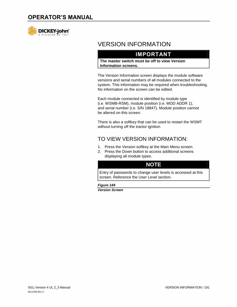
OPERATOR’S MANUAL
ISO6 Version 4 UL 2_3 Manual VERSION INFORMATION / 191
6011258 Rev C
VERSION INFORMATION
IMPORTANT
The master switch must be off to view Version
Information screens.
The Version Information screen displays the module software
versions and serial numbers of all modules connected to the
system. This information may be required when troubleshooting.
No information on the screen can be edited.
Each module connected is identified by module type
(i.e. WSMB-RSM), module position (i.e. MOD ADDR 1),
and serial number (i.e. S/N 18847). Module position cannot
be altered on this screen.
There is also a softkey that can be used to restart the WSMT
without turning off the tractor ignition.
TO VIEW VERSION INFORMATION:
1. Press the Version softkey at the Main Menu screen.
2. Press the Down button to access additional screens
displaying all module types.
NOTE
Entry of passwords to change user levels is accessed at this
screen. Reference the User Level section.
Figure 149
Version Screen

OPERATOR’S MANUAL
192 / VERSION INFORMATION ISO6 Version 4 UL 2_3 Manual
6012487 Rev A

OPERATOR’S MANUAL
193 / FACTORY RESET ISO6 Version 4 UL 2_3 Manual
6011258 Rev C
FACTORY RESET (USER LEVEL 3)
Level 3 Users have access to restore system settings to:
FACTORY DEFAULTS - restores configuration files to
factory defaults.
OVERWRITE DEFAULTS - configuration files set by the
user that overwrites factory defaults.
CAUTION
Performing a factory reset should be completed by an
authorized service technician. Restoring or overwriting
current configuration files removes the user-defined
configuration settings. User-defined configuration files
can be exported to a USB memory device for importing a
later time, if desired.
TO RESET MEMORY:
1. Press the FACTORY RESET button.
2. Select the button type to Reset to Defaults.
3. Press the Checkmark button to begin system reset.
- Press the Cancel ‘X’ button to cancel reset.
TO CHANGE DEFAULTS:
1. Press the FACTORY RESET button.
2. Press Replace Defaults or Factory Defaults.
- Replace Defaults overwrites the system defaults to the
current system configuration.
- Factory Defaults sets the system defaults to the defaults
programmed from the factory.
3. Press the Checkmark button to begin system reset.
- Press the Cancel ‘X’ button to cancel reset.
Figure 150
Factory Reset Screen

OPERATOR’S MANUAL
ISO6 Version 4 UL 2_3 Manual ALARMS / 194
6011258 Rev C
ALARMS
Alarms display when an abnormal event occurs outside of
normal parameters. Alarms are typically in a full screen display
describing the alarm and may give instructions on how to fix the
alarm. Each alarm has an associated alarm number. Some
alarms (such as the master/control switch alarm) require a
specific action by the operator before the alarm condition will
cease. In these cases, instructions are indicated on the
alarm display.
Alarms can be acknowledged by pressing the CANCEL button.
Detailed information about the alarm can be accessed by
pressing the ALARM INFO button.
ALARM LOG AND DETAILS
An Alarm Log provides a list of specific alarms issued during
system operation. Information displayed is informational only and
cannot be edited. Each time specific alarm conditions are
detected, it is logged and communicated to the ISO6 module.
TO VIEW ALARM LOG AND INFO:
1. Press the ALARM LOG button.
2. At the Alarm Log screen, a list of alarms displays.
- Alarm number and description displays
- Up to 20 alarms can be recalled
- Each alarm occurrence can have up to 5 instances of
the alarm tagged with a date and time stamp.
3. To select specific alarm details, press the Previous or Next
buttons to move the small display arrow next to the desired
alarm number.
4. Press the ALARM INFO button to view all of the
occurrences of the selected alarm.
- The down arrow in the lower left at screen bottom
signifies that more alarms are present and accessible by
pressing the Previous or Next buttons.
Figure 151
Alarm Log and Detail Screen

OPERATOR’S MANUAL
ISO6 Version 4 UL 2_3 Manual ALARMS / 195
6012487 Rev A
ALARM RESET (LEVEL 3 OEM USER)
OEM Level users have access to clear logged alarms. To reset
the Alarm Log, press the Alarm Reset button.
1. Press the Checkmark button to clear.
2. Press the ‘X’ button to retain alarm log and return to
Alarm Log screen.
Figure 152
Alarm Reset

OPERATOR’S MANUAL
ISO6 Version 4 UL 2_3 Manual DIAGNOSTICS / 196
6011258 Rev C
DIAGNOSTICS
The Diagnostics screen provides information from feedback
sensors, valve output, and system voltages of the planter drill
control. The control valve can be manually opened on this
screen when necessary.
Each channel has its own Diagnostics screen. Items on the
screen are not editable, but the Channel Pulse Count data is
re-settable. The system can be active on the Diagnostics screen.
DANGER
When the START key is engaged, the machine will
become operational. All necessary precautions must be
taken to ensure user safety. Failure to practice all
necessary caution may result in serious injury or death.
Figure 153
Diagnostics Screen
TARGET RATE
Channel Target is the current channel’s rate as entered into the
Target Rate constant on the Controls Configuration screen.
TARGET SPEED
The calculated RPM or flow rate for the current channel.

OPERATOR’S MANUAL
ISO6 Version 4 UL 2_3 Manual DIAGNOSTICS / 197
6011258 Rev C
SETPOINT
Channel Setpoint is calculated by the system displaying the
expected feedback frequency of the application rate sensor or
flow meter used for that channel’s feedback.
PWM
The Channel PWM value is the current pulse width modulation
(PWM) output drive signal to the solenoid valve. The higher the
number, the further the valve opens.
ACTUAL RATE
The Channel Actual Rate value is the current channel’s actual
controlled rate with the system active.
ACTUAL SPEED
The channel’s actual RPM or flow rate.
FEEDBACK FREQUENCY
Feedback frequency is the current channel’s feedback frequency
of the application rate sensor or flow meter used for that
channel’s feedback.
PULSE COUNT
The Channel Pulse Count value is the accumulated pulse count
detected from the channel feedback sensor. This value may be
reset by the operator by pressing the Reset Channel Pulse
Count button.
FREQ GSPD
Ground Speed Frequency is the feedback frequency of the
ground speed sensor. Ground Speed Frequency is only shown
when using Digital Frequency or Reluctance Frequency settings
for Ground Speed.
NOTE
If the values are reversed and the value displays a “lowered”
when the implement is raised, the wiring for the implement
switch will need to be reversed so that an accurate readout is
achieved.
IO IMP LIFT
The IO Implement Lift value displays the current state of the
implement status switch. This text states “lowered” when the
implement is down. The text states “raised” when the implement
is raised.
OPERATOR’S MANUAL
198 / DIAGNOSTICS ISO6 Version 4 UL 2_3 Manual
6011258 Rev C
SOLENOID POWER
The Solenoid Power Volt value displays the detected solenoid
power voltage. This voltage level is the high current voltage leg
of the system which is used to power high current solenoids and
valve actuators. This value will generally be equal or nearly
equal to the tractor battery voltage.
ECU POWER
The Electrical Control Unit (ECU) Power Volt value is the
detected ECU voltage. This voltage level is the low current
voltage leg of the system and is used to power modules and
sensors. This value will generally be equal or nearly equal to the
tractor battery voltage.
SENSOR POWER
The Sensor Power Volt value is the detected output voltage to
the seed sensor on the ISO6 module. This value is typically
+8 VDC.
GROUND OFFSET
Measures the difference between the ECU ground and the
solenoid ground. This value is typically between -0.5V and
+0.5V. Values below -2.0V and above +2.0V triggers the
Ground Offset Voltage Out of Range alarm.
MANUAL OPEN OF CHANNEL (SYSTEM FAILURE)
Manual opening of a selected channel’s valve is used for
calibration or troubleshooting purposes in the case of system
failure. This procedure should only be performed with the
guidance of an authorized technician.
DANGER
When the START key is engaged, the machine will
become operational. All necessary precautions must be
taken to ensure user safety. Failure to practice all
necessary caution may result in serious injury or death.
TO MANUALLY OPEN CHANNEL:
1. At the Controls screen for the appropriate channel, set the
Control Mode to either Manual with Feedback or Manual
without Feedback.
2. Press the Home button to return to the Home Menu and
select the DIAGNOSTICS button.
3. Go to the Diagnostics screen.

OPERATOR’S MANUAL
ISO6 Version 4 UL 2_3 Manual DIAGNOSTICS / 199
6011258 Rev C
- The Diagnostics screen will show Channel 1 as
a default.
- If a channel other than Channel 1 needs selected, press
the Down button until the appropriate channel displays.
The Down button only displays when more than one
channel is configured.
4. Set the master switch to the ON position or press the
START button.
5. Make sure the implement is down.
6. Press the Increment button to open the channel’s valve. The
Channel Pulse Width Modulation (PWM) data item displays
the current PWM signal that is output to the valve.
- The Increment button must be pressed repeatedly to
increase the PWM signal to the valve. Each press will
increase the signal by 2% PWM. The Channel Pulse
Count and Channel Frequency Filter values display the
current output of the feedback sensor.
7. Press the Decrement button to decrease the PWM signal
and close the valve. The Decrement button must be pressed
repeatedly to decrease the PWM signal to the valve. Each
press decreases the signal by 2% PWM.
- The active channel displays in the button text.
8. Turn the master switch off to shutdown control channel or
press the STOP button.
9. Press the Home button and select the CONTROLS button to
reset Control Mode to Auto.

OPERATOR’S MANUAL
200 / DIAGNOSTICS ISO6 Version 4 UL 2_3 Manual
6011258 Rev C
Figure 154
Manual Open of a Channel

OPERATOR’S MANUAL
201 / SOFTWARE ADD-ONS ISO6 Version 4 UL 2_3 Manual
6011258 Rev C
SOFTWARE ADD-ONS
The FEATURE KEYS screen displays customer-specific add-ons
to the specific master module. Each line item identifies the
module name and details that may be required for
troubleshooting purposes. This screen is viewable only and
cannot be changed.
TO VIEW FEATURE KEYS:
1. Press the SYSTEM button.
2. At the System screen, press the FEATURE KEYS button.
- All add on software displays onscreen.
3. Press the NEXT button to view additional feature keys.
Figure 155
Feature Keys Screen
FEATURE KEY POSSIBLE ADD-ONS
Additional functionality is available by adding FEATURE KEYS
and includes:
Frame Folding/Working Hydraulics
Advanced Seed Data
Channel expansion (3,4,5,6,7,8)
Tramlining
IRC
Virtual Section Switches

OPERATOR’S MANUAL
ISO6 Version 4 UL 2_3 Manual TROUBLESHOOTING AND ALARM CODES / 202
6011258 Rev C
TROUBLESHOOTING & ALARM CODES
Alarms are presented in a full screen display with description
and resolution instructions, if applicable. Each alarm type has
an associated alarm number that can be cross-referenced in
this section.
An audible alarm is terminated by pressing the
ALARM CANCEL button or ESC key. In addition, detailed
descriptions of the current alarm can be viewed by pressing the
ALARM DETAIL button.
Some alarms (e.g. Master Switch alarm) require a specific action
before the alarm condition will cease. In these cases, the
instructions to proceed are indicated in the alarm display.
Figure 156
Alarm Screen for Alarm Number 218

OPERATOR’S MANUAL
ISO6 Version 4 UL 2_3 Manual TROUBLESHOOTING AND ALARM CODES / 203
6011258 Rev C
The following tables describe the possible alarm conditions, causes, and remedies.
For troubleshooting assistance, please contact your local dealer.

OPERATOR’S MANUAL
204 / TROUBLESHOOTING AND ALARM CODES ISO6 Version 4 UL 2_3 Manual
6011258 Rev C
ALARM # ALARM PROBABLE CAUSE CORRECTIVE ACTION
5 Control CPU
Communications
Failed Alarm
Processor has automatically restarted or cannot boot.
1. Wait until intermittent alarm occurs
before running system.
2. Power off the system if intermittent
alarm does not appear.
3. If system does not recover, consult
dealer.
6 Control CPU
Communications
Intermittent Alarm
Processor that had previously failed communication has come online.
1. No action needed.
7 Monitor CPU
Communications
Failed Alarm
Processor has automatically restarted or cannot boot.
1. Wait until intermittent alarm occurs
before running system.
2. Power off the system if intermittent alarm
does not appear.
3. If system does not recover,
consult dealer.
8 Monitor CPU
Communications
Intermittent Alarm
Processor that had previously failed
communication has come online.
1. No action needed.
200 Master Switch Time Out Alarm
Master switch is active but no ground
speed is detected. If no speed is detected,
the master switch will deactivate.
1. Faulty master switch harness.
2. Faulty ground speed sensor/harness.
1. Press CANCEL to keep the master
switch active.
2. Inspect ground speed harnessing if
speed should be present.
201 Ground Speed
Communication
Failure Alarm
N
o
g
r
o
u
n
d
s
p
e
e
d
c
o
m
m
u
n
i
c
a
t
i
o
n
r
e
c
e
i
v
e
d
.
1. Faulty ground speed communication
harnessing.
2. Ground speed not present when it is
1
.
V
e
r
i
f
y
c
o
r
r
e
c
t
s
p
e
e
d
s
e
t
t
i
n
g
s
2
.
V
e
r
i
f
y
s
202 Ground Speed Failure Alarm
Only active in Planter Monitor mode.
No ground speed detected.
1. Incorrect speed source setting
or calibration.
2. Defective speed sensor or harness. 3. Defective module or universal terminal.
1. Verify correct speed source setting and
speed calibration on the Ground Speed
Calibration screen.
2. Inspect speed sensor/harness for
damage or replace speed sensor.
3. Replace module or universal terminal.
206 Control Channel Unable
to Control Alarm
Control channel is unable to achieve
the target rate.
1. Incorrect channel settings. 2. Incorrect feedback sensor installation. 3. Defective feedback sensor.
1. Verify correct setup constants on the Control Channel screen.
2. Perform a valve calibration. 3. Verify correct installation of the feedback
sensor. Inspect feedback sensor for
damage or replace.
4. Check control valve for damage. 5. Check harness and module for damage.

OPERATOR’S MANUAL
ISO6 Version 4 UL 2_3 Manual TROUBLESHOOTING AND ALARM CODES / 205
6011258 Rev C
207 Channel Unstable Alarm Control channel is unstable at the current target rate.
1. Incorrect channel settings. 2. Incorrect feedback sensor installation. 3. Defective feedback sensor.
1. Verify correct setup constants on the
Channel Configuration screen. Perform a
valve calibration.
2. Verify correct installation of the feedback sensor.
3. Inspect feedback sensor for damage
or replace.
4. Verify system is stable using Manual
Control Mode.
208 Channel Saturation Exceeded Alarm
Control cannot obtain the specified rate.
1. Excessive speed. 2. Incorrect channel settings. Desired rate
too high for implement.
3. Target rate too high.
1. Reduce speed. 2. Verify correct setup constants on the
Channel Configuration screen.
3. Perform a valve calibration and a
Calibration constant.
4. Inspect feedback sensor, motor and
harnessing.
5. Reduce target rate.
209 Control High Limit Alarm Feedback has exceeded the material High Limit setting.
1. Target Rate too high. 2. Ground speed too low.
1. Reduce speed or Target Rate. 2. Verify material High Limit setting. 3. Review control channel setup.
210 Control Low Limit Alarm Feedback has dropped below the material Low Limit setting.
1. Target Rate too low. 2. Ground speed too high.
1. Increase speed or Target Rate. 2. Verify material Low Limit setting. 3. Review control channel setup.
211 All Rows Failed Alarm Seeding was not detected on any rows.
1. Seed meter drive malfunction. 2. Rows are not assigned to channel and
channels are turned off.
1. Check seeding drive(s). 2. Assign rows to channel. 3. Inspect sensors and harnessing
for damage.
212 Row Failure Alarm Seed rate has fallen below the row fail rate
setting on the Seed Monitor Setup screen.
1. Seed meter malfunction. 2. Dirty or defective seed sensor. 3. Damaged planter harness. 4. Defective module harness or module. 5. Out of seed.
1. Verify proper planter operation. 2. Inspect seed sensor for dirt or damage.
Replace if necessary.
3. Inspect planter harness for damage.
Repair or replace.
4. Inspect harness and module for damage.
Replace if necessary.
5. Fill with seed. 6. Review material settings.

OPERATOR’S MANUAL
206 / TROUBLESHOOTING AND ALARM CODES ISO6 Version 4 UL 2_3 Manual
6011258 Rev C
ALARM
#
ALARM PROBABLE CAUSE CORRECTIVE ACTION
213 High Population Limit Exceeded Alarm
Seed rate has exceeded the High Alarm
Setting on the Seed Monitor Setup screen.
1. Seed meter malfunction or
incorrect setup.
2. Defective seed sensor. 3. Defective module.
1. Verify proper planter options/setup. 2. Inspect seed sensor for damage.
Replace if necessary.
3. Inspect module for damage. Replace if
necessary.
4. Review material settings.
214 Low Population Limit Exceeded Alarm
Seed rate has dropped below the Low Pop
Alarm Setting on the Seed Monitor Setup
screen.
1. Seed meter malfunction or incorrect setup.
2. Defective seed sensor. 3. Defective module. 4. Running out of seed.
1. Verify proper planter operation/setup. 2. Inspect seed sensor for
damage. Replace if necessary.
3. Inspect module for damage. Replace if necessary.
4. Fill with seed.
215 High Pressure Limit Exceeded Alarm
Sensed pressure exceeds the high alarm setting on the Pressure Setup screen.
1. Implement malfunction or
incorrect setup.
2. Defective pressure sensor. 3. Defective module.
1. Verify proper implement operation/setup.
2. Inspect pressure sensor for
damage. Replace if necessary.
3. Inspect module for damage.
Replace if necessary.
216 Low Pressure Limit Exceeded Alarm
Sensed pressure below the low alarm setting on the Pressure Setup screen.
1. Implement malfunction or incorrect setup. 2. Defective pressure sensor. 3. Defective module harness or module.
1. Verify proper implement operation/setup. 2. Inspect pressure sensor for damage.
Replace if necessary. 3. Inspect module and/or module harness
for damage. Replace if necessary.
217 Member Module Detection Alarm
Number of modules detected does not match the expected modules configured.
1. Too few modules connect to system. 2. Too many modules connected to
system. 3. Defective CAN/module harness. 4. Blown module harness fuse. 5. Defective module. 6. New module has been added
to system.
1. Verify correct module configuration
setup on the Module Configuration
screen.
2. Verify correct module configuration
setup on the Module Configuration
screen.
3. Identify missing module in the Module Configuration list. Inspect CAN/module harness of the missing module for damage. Repair or replace harness.
4. Inspect module harness fuse of the
identified module. Replace if
necessary.
5. Identify missing module in the Module Configuration list. Inspect missing module for damage or replace.
6. Verify correct module configuration setup on the Module Configuration screen.
218 Accessory Sensor Detection Alarm
Number of accessory sensors detected
does not match the expected number
configured.
1. Defective Sensor. 2. Defective module or damaged
module harness.
3. Additional sensor detected but not configured in the Accessory Setup screen.
1. Inspect sensor for damage or
replace.
2. Inspect module and/or module
harness for damage. Replace if
necessary.
3. Verify correct# ACC setting for each module.
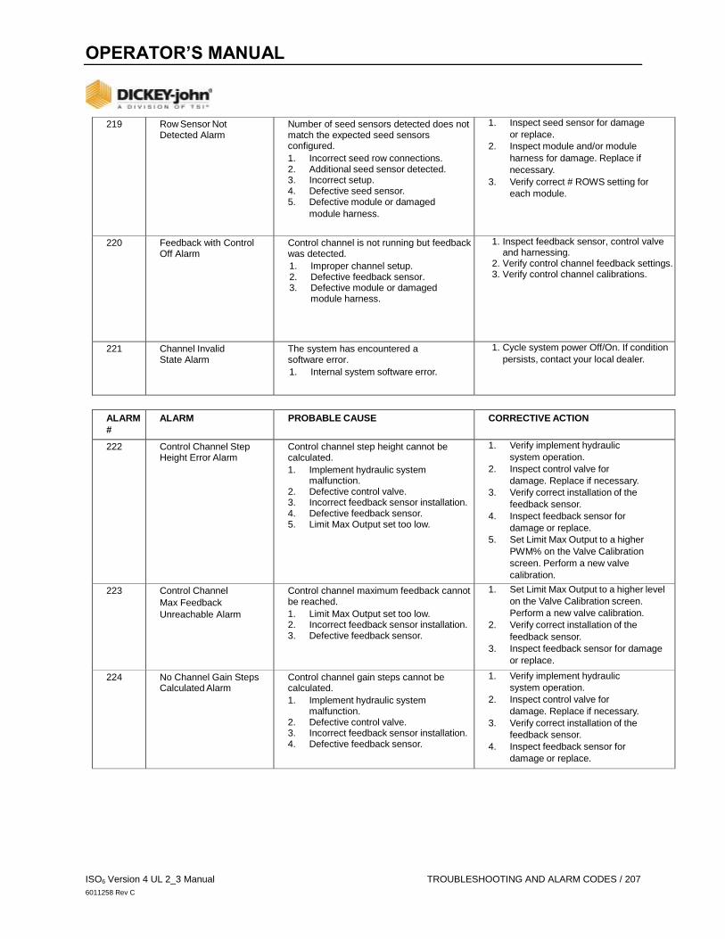
OPERATOR’S MANUAL
ISO6 Version 4 UL 2_3 Manual TROUBLESHOOTING AND ALARM CODES / 207
6011258 Rev C
219 Row Sensor Not Detected Alarm
Number of seed sensors detected does not match the expected seed sensors configured.
1. Incorrect seed row connections. 2. Additional seed sensor detected. 3. Incorrect setup. 4. Defective seed sensor. 5. Defective module or damaged
module harness.
1. Inspect seed sensor for damage
or replace.
2. Inspect module and/or module
harness for damage. Replace if
necessary.
3. Verify correct # ROWS setting for
each module.
220 Feedback with Control Off Alarm
Control channel is not running but feedback was detected.
1. Improper channel setup. 2. Defective feedback sensor. 3. Defective module or damaged
module harness.
1. Inspect feedback sensor, control valve and harnessing.
2. Verify control channel feedback settings. 3. Verify control channel calibrations.
221 Channel Invalid State Alarm
The system has encountered a software error.
1. Internal system software error.
1. Cycle system power Off/On. If condition
persists, contact your local dealer.
ALARM
#
ALARM PROBABLE CAUSE CORRECTIVE ACTION
222 Control Channel Step Height Error Alarm
Control channel step height cannot be calculated.
1. Implement hydraulic system malfunction.
2. Defective control valve. 3. Incorrect feedback sensor installation. 4. Defective feedback sensor. 5. Limit Max Output set too low.
1. Verify implement hydraulic
system operation.
2. Inspect control valve for
damage. Replace if necessary.
3. Verify correct installation of the
feedback sensor.
4. Inspect feedback sensor for
damage or replace.
5. Set Limit Max Output to a higher
PWM% on the Valve Calibration
screen. Perform a new valve
calibration.
223 Control Channel
Max Feedback
Unreachable Alarm
Control channel maximum feedback cannot be reached.
1. Limit Max Output set too low. 2. Incorrect feedback sensor installation. 3. Defective feedback sensor.
1. Set Limit Max Output to a higher level
on the Valve Calibration screen.
Perform a new valve calibration.
2. Verify correct installation of the
feedback sensor.
3. Inspect feedback sensor for damage
or replace.
224 No Channel Gain Steps Calculated Alarm
Control channel gain steps cannot be calculated.
1. Implement hydraulic system malfunction.
2. Defective control valve. 3. Incorrect feedback sensor installation. 4. Defective feedback sensor.
1. Verify implement hydraulic
system operation.
2. Inspect control valve for
damage. Replace if necessary.
3. Verify correct installation of the
feedback sensor.
4. Inspect feedback sensor for
damage or replace.

OPERATOR’S MANUAL
208 / TROUBLESHOOTING AND ALARM CODES ISO6 Version 4 UL 2_3 Manual
6011258 Rev C
225 Hopper Sensor Low Alarm The hopper level is low.
1. Incorrect logic level setting on the Hopper Setup screen.
2. Dirty or defective hopper sensor. 3. Defective module harness or module. 4. Hopper empty.
1. Verify correct logic level setting on the Hopper Setup screen.
2. Clean/inspect hopper sensor. Replace if necessary.
3. Inspect harness and module for damage. Replace if necessary.
4. Fill hopper.
226 RPM High Limit Alarm Sensed RPM exceeds the high alarm
setting on the RPM or Control Setup
screen.
1. Implement malfunction or
incorrect setup.
2. Defective RPM sensor. 3. Defective module.
1. Verify proper implement operation/setup.
2. Inspect RPM sensor for
damage. Replace if necessary.
3. Inspect module for damage. Replace
if necessary.
227 RPM Low Limit Exceeded Alarm
Sensed RPM exceeds the low alarm
setting on the RPM or Control Setup
screen.
1. Implement malfunction or incorrect
setup.
2. Defective RPM sensor. 3. Defective module harness or module.
1. Verify proper implement operation/setup.
2. Inspect RPM sensor for
damage. Replace if necessary.
3. Inspect module for damage. Replace
if necessary.
229 Digital Sensor Alarm One or more digital sensors have entered an alarm state.
1. Incorrect logic level setting on the Digital Setup screen.
2. Dirty or defective digital sensor. 3. Defective module harness or module 4. Improper control of actuator that uses
digital sensor feedback.
1. Verify correct logic level setting on the Hopper Setup screen.
2. Clean/inspect hopper sensor. Replace if necessary.
3. Inspect harness and module for
damage. Replace if necessary.
4. Inspect connected actuator for
damage.
ALARM
#
ALARM PROBABLE CAUSE CORRECTIVE ACTION
232 Control Channel Shutdown Alarm
RPM has dropped below the disable
control on low alarm setting on the
Accessory Setup screen.
1. Defective RPM sensor. 2. Damaged module harness. 3. Defective module. 4. Low RPM.
1. Inspect RPM sensor for damage.
Replace if necessary.
2. Inspect module harness for damage.
Repair or replace.
3. Inspect module for damage. Replace if necessary.
4. Increase RPM.
235 New Member Module Detected Alarm
New member module has been found. 1. Assign sensors to the new module at
the Module Configuration Setup
screen and its position.
236 Intermittent Member Module Detected Alarm
A member module that had previously
failed communication has come online.
1. Inspect harness connections to
this module.
237 Product Level Low Alarm Estimated product level has dropped
below alarm level.
1. Fill product bin and reset level.
241 Seeding Detected on a Control Off Row Alarm
Seed rate detected on an off row.
1. Defective row sensor. 2. Control shutoff malfunction. 3. Improper row channel assignment.
1. Inspect harness and module
for damage.
2. Check control shutoff.
3. Verify correct row to control
channel assignment.

OPERATOR’S MANUAL
ISO6 Version 4 UL 2_3 Manual TROUBLESHOOTING AND ALARM CODES / 209
6011258 Rev C
248 BSM/ESM Communication Lost Alarm
BSM has lost communication with an ESM.
1. Damaged CAN or module harness. 2. Blown module harness fuse. 3. Defective module.
1. Identify missing module in the
Module Configuration list. Inspect
CAN/module harness of the missing
module for damage. Repair or
replace harness.
2. Inspect module harness fuse, replace if necessary.
3. Identify missing module in the
Module Configuration list. Inspect
missing module for damage or
replace.
249 BSM/ESM Foot Switch Lost Alarm
BSM has detected an error with the foot switch.
1. Incorrect foot switch connections. 2. Defective BSM or foot switch. 3. Defective module harness.
1. Inspect BSM, foot switch, and
module harness.
256 Channel Invalid Material Alarm
No material exists that is compatible with
channel type.
1. Setup a material for the channel type. 2. Review control setup.
ALARM
#
ALARM PROBABLE CAUSE CORRECTIVE ACTION
272 Defaults Loaded Alarm System configuration is corrupt and has
been reset to default settings.
1. Error code provided for cause.
1. Check system configuration for
correctness. If this persists, contact
dealer for support
300 Disconnected from Task Controller Alarm
System configuration has changed and the
connection to the task controller has been
disconnected.
1. Continue setup and restart system or restart using the RECONNECT key on the TASK CONTROLLER screen.
301 Task Controller Rate Override Alarm
The commanded rate from the task
controller has been manually overridden.
1. Press the Reset button to return to
the commanded rate.
2. Review Rate Override setup.
602 8 Volt Supply Failure Alarm
8V supply voltage rail is below 7.2V or higher than 16V.
1. Damaged module harness. 2. Defective seed or hopper sensor. 3. Defective module.
1. Inspect module harness for damage.
Repair or replace harness.
2. Inspect seed or hopper sensors connected to the identified module for damage. Replace sensors if necessary.
3. Replace identified module.
603 Member Module
Communication
Failed Alarm
Communication with an active member module has failed.
1. Damaged CAN or module harness. 2. Blown module harness fuse. 3. Defective module.
1. Identify missing module in the
Module Configuration list. Inspect
CAN/module harness of the missing
module for damage. Repair or
replace harness.
2. Inspect module harness fuse, replace
if necessary.
3. Identify missing module in the Module
Configuration list. Inspect missing
module for damage or replace.
604 ECU Voltage Alarm ECU voltage is below 11V or higher than 16V.
1. Damaged CAN or module harness. 2. Defective module
1. Inspect CAN/module harness of
the identified module for damage.
2. Inspect identified module for damage
or replace.

OPERATOR’S MANUAL
210 / TROUBLESHOOTING AND ALARM CODES ISO6 Version 4 UL 2_3 Manual
6011258 Rev C
605 Solenoid Voltage Alarm Solenoid voltage is below 11V or higher than 16V.
1. Damaged CAN or module harness. 2. Blown module harness fuse. 3. Defective module.
1. Inspect CAN/module harness of
the identified module for damage.
Repair or replace harness.
2. Inspect module harness fuse or replace.
3. Inspect identified module for damage
or replace.
606 Ground Offset Voltage Alarm
The ground offset is below -2V or above 2V.
1. Damaged/shorted Actuator Harness. 2. Defective PWM valve driver or
Servo valve driver.
3. Defective module.
1. Inspect Actuator Harness for
damage around the WPM and
Servo valve connections. Repair or
replace harness.
2. Inspect PWM or Servo valve drivers
for damage and replace if necessary.
3. Inspect identified module for
damage and replace if necessary.

211 / WARRANTY ISO6 Version 4 UL 2_3 Manual
6011258 Rev C
Dealers have the responsibility of calling to the attention of their customers the following
warranty prior to acceptance of an order from their customer for any DICKEY-john product.
DICKEY-john® WARRANTY DICKEY-john warrants to the original purchaser for use that, if any part of the product proves to be
defective in material or workmanship within one year from date of original installation, and is returned
to DICKEY-john within 30 days after such defect is discovered, DICKEY-john will (at our option)
either replace or repair said part. This warranty does not apply to damage resulting from misuse,
neglect, accident, or improper installation or maintenance; any expenses or liability for repairs made
by outside parties without DICKEY-john’s written consent; damage to any associated equipment; or
lost profits or special damages. Said part will not be considered defective if it substantially fulfills the
performance expectations. THE FOREGOING WARRANTY IS EXCLUSIVE AND IN LIEU OF ALL
OTHER WARRANTIES OF MERCHANTABILITY, FITNESS FOR PURPOSE, AND OF ANY OTHER
TYPE, WHETHER EXPRESS OR IMPLIED. DICKEY-john neither assumes nor authorizes anyone to
assume for it any other obligation or liability in connection with said part and will not be liable for
consequential damages. Purchaser accepts these terms and warranty limitations unless the product
is returned within fifteen days for full refund of purchase price.
For DICKEY- john Service Department, call +1-800-637-3302 in either the U.S.A. or Canada
5200 Dickey John Road, Auburn, IL USA 62615
TEL: +1 217 438 3371, E-MAIL: [email protected], WEB: www.dickey-john.com
© 2019 DICKEY-john
Specifications subject to change without notice.

ISO6 is a trademark, and DICKEY-john, and the DICKEY-john Logo are registered trademarks of DICKEY-john.
P/N 6011258 Rev C
Ope
rato
r’s M
anua
l U
ser L
evel
2/3
5200 Dickey John Road Auburn, IL 62615www.dickey-john.com
+1 217-438-3371 +1 217-438-6012 fax©2019 DICKEY-john
INTELLIAG® IS06™
PLANTER DRILL CONTROLVERSION 4
DICKEY-john Sales+1 800-637-2952 [email protected]
DICKEY-john Technical Support+1 800-637-3302 [email protected]
A D I V I S I O N O F T S I ®
®