a distributed platform for the volunteer execution of ... · jaquilino lopes silva bachelor of...
TRANSCRIPT

Jaquilino Lopes Silva
Bachelor of Science in Computer Science
A Distributed Platform for the VolunteerExecution of Workflows on a Local Area
Network
Thesis submitted in fulfilment of the requirements for the Degree ofMaster of Science inComputer Science
Adviser : Dr. Hervé Miguel Cordeiro Paulino, Assistant Profes-sor, FCT-UNL
Co-adviser : Dr. Francisco de Moura e Castro Ascensão deAzevedo, Assistant Professor, FCT-UNL
Jury:
Chairman: Dr. Nuno Manuel Robalo Correia, Full Professor,FCT-UNL
Main referee: Dr. Paulo Jorge Pires Ferreira, Associate Profes-sor, IST
Other member of the jury: Dr. Hervé Miguel Cordeiro Paulino, Assistant Pro-fessor, FCT-UNL
June, 2014


iii
A Distributed Platform for the Volunteer Execution of Workflows on a LocalArea Network
Copyright c© Jaquilino Lopes Silva, Faculdade de Ciências e Tecnologia, UniversidadeNova de Lisboa
A Faculdade de Ciências e Tecnologia e a Universidade Nova de Lisboa têm o direito,perpétuo e sem limites geográficos, de arquivar e publicar esta dissertação através de ex-emplares impressos reproduzidos em papel ou de forma digital, ou por qualquer outromeio conhecido ou que venha a ser inventado, e de a divulgar através de repositórioscientíficos e de admitir a sua cópia e distribuição com objetivos educacionais ou de in-vestigação, não comerciais, desde que seja dado crédito ao autor e editor.

iv

I dedicate this dissertation to my family, to all friends andclassmates from high school to university. A special feeling ofgratitude to my grandmother, Maria, who always encouraged
me to take this master course.

vi
Acknowledgements
Many thanks to Prof. Dr. Hervé Paulino for being my adviser and for all time spent help-ing me during the elaboration of this MSc dissertation. In the same way, I would liketo thank my co-adviser Prof. Dr. Francisco Azevedo for having invited Prof. Dr. HervéPaulino to coordinate this dissertation in collaboration with him and for all supporting.Yours technical background and skills have contributed significantly to the success of thiswork. You were excellent for me!
I also would like to dedicate this dissertation to all my co-workers from AlbatrozEngineering, who supported and advised me whenever I needed to clarify some doubtsabout system requirements. Special thanks go to Eng. Miguel Ramos, Eng. Tiago Gusmãoand Eng. Gomes Mota. Without their supporting may be the realization of this workwould not be possible.
Finally, I would like to acknowledge and thank Albatroz Engineering for having par-tially funded this work and provided enough computing resources to test the developedsystem.
Thank you very much!
vii

viii ACKNOWLEDGEMENTS
Abstract
Albatroz Engineering has developed a framework for over-head power lines inspec-tion data acquisition and analysis, which includes hardware and software. The frame-work’s software components include inspection data analysis and reporting tools, com-monly known as PLMI2 application/platform.
In PLMI2, the analysis of over-head power line maintenance inspection data consistsof a sequence of Automatic Tasks (ATs) interleaved with Manual Tasks (MTs). An ATconsists of a set of algorithms that receives as input one or more datasets, processes themand returns new datasets. In turn, an MT enables human supervisors (also known aslines inspection operators) to correct, improve and validate the results of ATs. ATs runfaster than MTs and in the overall work cycle, ATs take less than 10% of total processingtime, but still take a few minutes. There is data flow dependency among tasks, whichcan be modelled with a workflow and even if MTs are omitted from this workflow, it ispossible to carry the sequence of ATs, postponing MTs.
In fact, if the computing cost and waiting time are negligible, it may be advantageousto run ATs earlier in the workflow, prior to validation. To address this opportunity, Al-batroz Engineering has invested in a new procedure to stream the data through all ATsfully unattended.
Considering these scenarios, it could be useful to have a system capable of detectingavailable workstations at a given instant and subsequently distribute the ATs to them.In this way, operators could schedule the execution of future ATs for a given inspectiondata, while they are performing MTs of another.
The requirements of the system to implement fall within the field Volunteer Comput-ing Systems and we will address some of the challenges posed by these kinds of systems,namely the hosts volatility and failures. Volunteer Computing is a type of distributedcomputing which exploits idle CPU cycles from computing resources donated by volun-teers and connected through the Internet/Intranet to compute large-scale simulations.
This thesis proposes and designs a new distributed task scheduling system in the
ix

x ABSTRACT
context of Volunteer Computing Systems, able to schedule the ATs of PLMI2 and exploitidle CPU cycles from workstations within the company’s local area network (LAN) toaccelerate the data analysis, being aware of data flow interdependencies.
To evaluate the proposed system, a prototype has been implemented, and the simula-tions results have shown that it is scalable and supports fault-tolerance of tasks execution,by employing the rescheduling mechanism.
Keywords: Volunteer Computing system, Interdependent tasks, Distributed task schedul-ing, Fault-tolerance, Scalability

Resumo
A Albatroz Engenharia SA desenvolveu um sistema de aquisição e análise de da-dos das inspeções de linhas elétricas, que inclui hardware e software. Os componentes desoftware incluem ferramentas de análise e elaboração dos relatórios das inspeções, conhe-cidas como PLMI2.
A análise dos dados de uma inspeção no PLMI2 consiste numa sequência de TarefasAutomáticas (TAs), intercaladas com Tarefas Manuais (TMs).
Uma TA consiste num conjunto de algoritmos que recebem como entrada um ou maisconjuntos de dados, processa-os e cria novos conjuntos de dados. Por sua vez, umaTM permite aos supervisores humanos (também conhecidos como operadores) corrigir,melhorar e validar os resultados das TAs. As TAs executam com maior rapidez do queas TMs, e no ciclo geral de processamento dos dados de uma inspeção, demoram menosde 10% do tempo total, mas ainda na ordem dos minutos. Há uma dependência no fluxode dados entre as tarefas, que pode ser modelada como um workflow e se as TMs foremomitidas deste workflow, é também possível realizar a sequência das TAs, adiando TMs.
De facto, se o custo da computação e o tempo de espera forem desprezáveis, podeser vantajoso executar as TAs no início do workflow, antes do processo de validação pe-los operadores. Para abordar essa oportunidade, a Albatroz Engenharia tem investidonum novo procedimento alternativo para fazer transmitir os dados entre todas as TAstotalmente autónoma.
Considerando estes cenários, seria útil dispor de um sistema capaz de detetar que asestações de trabalho estão livres num determinado instante e subsequentemente distri-buir as TAs por elas. Deste modo, os operadores poderão agendar a execução das pró-ximas TAs para um determinado conjunto de dados de uma inspeção, enquanto estão afazer as TMs de um outro conjunto de dados.
Os requisitos do sistema a implementar enquadram-se no âmbito dos Sistemas deComputação Voluntária (SCV) e vamos abordar alguns dos desafios impostos por essestipos de sistemas. Computação Voluntária é um tipo de computação distribuída que
xi

xii RESUMO
tira partido de ciclos livres dos recursos de computação doados por voluntários (i.e.,os proprietários dos recursos) e que estão ligados através da Internet ou Intranet para acomputação de simulações de grande escala. Pretendemos desenvolver um novo sistemade escalonamento de tarefas no contexto dos SCV, capaz de agendar as TAs do PLMI2e explorar os ciclos livres de CPU das estações de trabalho presentes na rede local daempresa (i.e., na LAN) para acelerar a análise dos dados, tendo em consideração as suasinterdependências.
Esta tese propõe e desenha um novo sistema de agendamento distribuído de tarefasno contexto da Computação Voluntária, capaz de agendar as TAs do PLMI2 e explorar osciclos livres de CPU das estações de trabalho dentro da LAN, para executar essas tarefas,tendo em consideração os requisitos definidos pela Albatroz Engenharia.
Para avaliar o sistema proposto, foi implementado um protótipo e os resultados dassimulações mostram que este é escalável e suporta tolerância a falhas na execução dastarefas, recorrendo a um mecanismo de reescalonamento das tarefas.
Palavras-chave: Computação Voluntária, Interdependências entre tarefas, Sistema deescalonamento distribuído de tarefas, Tolerância a falhas, Escalabilidade

Contents
Acknowledgements vii
Abstract ix
Resumo xi
1 Introduction 11.1 Motivation . . . . . . . . . . . . . . . . . . . . . . . . . . . . . . . . . . . . . 31.2 Problem Description . . . . . . . . . . . . . . . . . . . . . . . . . . . . . . . 41.3 Context . . . . . . . . . . . . . . . . . . . . . . . . . . . . . . . . . . . . . . . 61.4 Solution . . . . . . . . . . . . . . . . . . . . . . . . . . . . . . . . . . . . . . 81.5 Contributions . . . . . . . . . . . . . . . . . . . . . . . . . . . . . . . . . . . 81.6 Document Organization . . . . . . . . . . . . . . . . . . . . . . . . . . . . . 9
2 State of the Art 112.1 Introduction . . . . . . . . . . . . . . . . . . . . . . . . . . . . . . . . . . . . 112.2 Job Scheduling System . . . . . . . . . . . . . . . . . . . . . . . . . . . . . . 12
2.2.1 Scheduling Architectures . . . . . . . . . . . . . . . . . . . . . . . . 132.2.2 Resource Discovery . . . . . . . . . . . . . . . . . . . . . . . . . . . . 152.2.3 Job Scheduling Policy . . . . . . . . . . . . . . . . . . . . . . . . . . 162.2.4 Job Dispatching . . . . . . . . . . . . . . . . . . . . . . . . . . . . . . 18
2.3 Job scheduling in Volunteer Computing Systems . . . . . . . . . . . . . . . 182.3.1 Scheduling . . . . . . . . . . . . . . . . . . . . . . . . . . . . . . . . . 19
2.4 Peer-to-Peer Approach to Scheduling . . . . . . . . . . . . . . . . . . . . . . 202.5 Scheduling of Interdependent Tasks . . . . . . . . . . . . . . . . . . . . . . 222.6 Discussion . . . . . . . . . . . . . . . . . . . . . . . . . . . . . . . . . . . . . 24
3 The Distributed Execution Platform 253.1 Requirements . . . . . . . . . . . . . . . . . . . . . . . . . . . . . . . . . . . 253.2 Overall Architecture . . . . . . . . . . . . . . . . . . . . . . . . . . . . . . . 26
xiii
xiv CONTENTS
3.3 Task Identification and Contents . . . . . . . . . . . . . . . . . . . . . . . . 293.4 Communication: Client-application↔ Server-node . . . . . . . . . . . . . 293.5 Communication: Server-node↔ Running Task . . . . . . . . . . . . . . . . 323.6 Communication: Server-node↔ Server-node . . . . . . . . . . . . . . . . . 33
3.6.1 Master Election . . . . . . . . . . . . . . . . . . . . . . . . . . . . . . 343.6.1.1 Fault-tolerance . . . . . . . . . . . . . . . . . . . . . . . . . 353.6.1.2 Properties . . . . . . . . . . . . . . . . . . . . . . . . . . . . 38
3.6.2 Scheduling and Distributed Execution of Tasks . . . . . . . . . . . . 383.6.2.1 Fault-tolerance . . . . . . . . . . . . . . . . . . . . . . . . . 403.6.2.2 Properties and assumptions . . . . . . . . . . . . . . . . . 42
3.6.3 Server-node Joining/Leaving . . . . . . . . . . . . . . . . . . . . . . 43
4 Implementation 454.1 Introduction . . . . . . . . . . . . . . . . . . . . . . . . . . . . . . . . . . . . 454.2 Task Interface . . . . . . . . . . . . . . . . . . . . . . . . . . . . . . . . . . . 464.3 Integration of a New Task in the System . . . . . . . . . . . . . . . . . . . . 464.4 Inter-tasks Dependencies . . . . . . . . . . . . . . . . . . . . . . . . . . . . . 474.5 Server-node Module . . . . . . . . . . . . . . . . . . . . . . . . . . . . . . . 484.6 Execution Logging . . . . . . . . . . . . . . . . . . . . . . . . . . . . . . . . 52
5 Evaluation 555.1 Functional Evaluation . . . . . . . . . . . . . . . . . . . . . . . . . . . . . . 555.2 Experimental Evaluation . . . . . . . . . . . . . . . . . . . . . . . . . . . . . 55
5.2.1 Computing Resources . . . . . . . . . . . . . . . . . . . . . . . . . . 565.2.2 Simulation Framework . . . . . . . . . . . . . . . . . . . . . . . . . . 565.2.3 Test Configurations . . . . . . . . . . . . . . . . . . . . . . . . . . . . 575.2.4 Experimental Results . . . . . . . . . . . . . . . . . . . . . . . . . . . 58
5.3 Non-Functional Requirements Evaluation . . . . . . . . . . . . . . . . . . . 61
6 Conclusions and Future Works 63
A Appendix 71A.1 List of Acronyms . . . . . . . . . . . . . . . . . . . . . . . . . . . . . . . . . 71

List of Figures
1.1 A workflow with ATs and MTs intertwined. ATs are outlined with thegreen colour and MTs with purple. . . . . . . . . . . . . . . . . . . . . . . . 2
1.2 A general view of the current system architecture. . . . . . . . . . . . . . . 41.3 Another possible way to structure the workflow with the MTs on the up-
stream. . . . . . . . . . . . . . . . . . . . . . . . . . . . . . . . . . . . . . . . 5
2.1 The states of a job. . . . . . . . . . . . . . . . . . . . . . . . . . . . . . . . . . 132.2 Centralized scheduling architecture. Adapted from Li et al. [36]. . . . . . . 132.3 Distributed scheduling architectures. Adapted from Li et al. [36]. . . . . . 142.4 Hierarchical scheduling architecture. Adapted from Li et al. [36]. . . . . . . 152.5 The pull model for resource discovery. Adapted from Li et al. [36]. . . . . . 162.6 The push model for resource discovery. Adapted from Li et al. [36]. . . . . 162.7 The push-pull model for resource discovery. Adapted from Li et al. [36]. . 172.8 The architecture of PGS. Adapted from Cao et al. [37]. . . . . . . . . . . . . 21
3.1 A general view of proposed system architecture. . . . . . . . . . . . . . . . 283.2 Schedule an automatic task (client-application↔ server-node). . . . . . . 303.3 Subscribing interest in getting the progress and state of a set of tasks (client-
application↔ server-node). . . . . . . . . . . . . . . . . . . . . . . . . . . . 313.4 Progress reporting (server-node→ client-application). . . . . . . . . . . . . 313.5 Cancelling the execution of a task (client-application↔ server-node). . . . 323.6 Progress reporting (running task→ server-node). . . . . . . . . . . . . . . 333.7 Reporting the final results of a task (running task→ server-node ) . . . . . 333.8 Cancelling the execution of a task (server-node↔ running task) . . . . . . 343.9 An illustration of master election protocol. . . . . . . . . . . . . . . . . . . 373.10 An illustration of the ENQUEUE protocol. . . . . . . . . . . . . . . . . . . . 393.11 A system configuration on which can be minimized the race conditions. . 403.12 Example illustrating the interaction protocol for system’s state download-
ing by a joining node. . . . . . . . . . . . . . . . . . . . . . . . . . . . . . . . 44
xv

xvi LIST OF FIGURES
4.1 Overview of components of a server-node. . . . . . . . . . . . . . . . . . . 48
5.1 Workflow used for testing purposes. . . . . . . . . . . . . . . . . . . . . . . 585.2 System scalability with the increasing number of server-nodes. . . . . . . . 595.3 The average waiting time by a task in ready-to-run queue, according to the
number of server-nodes in the system. . . . . . . . . . . . . . . . . . . . . . 60

List of Tables
2.1 Description of job state. . . . . . . . . . . . . . . . . . . . . . . . . . . . . . . 122.2 A summary of advantages and disadvantages of centralized, distributed
and hierarchical scheduling. . . . . . . . . . . . . . . . . . . . . . . . . . . . 15
3.1 List of functional requirements . . . . . . . . . . . . . . . . . . . . . . . . . 263.2 List of non-functional requirements . . . . . . . . . . . . . . . . . . . . . . . 273.3 Format of the messages exchanged between a client-application and server-
node. . . . . . . . . . . . . . . . . . . . . . . . . . . . . . . . . . . . . . . . . 303.4 Format of the messages exchanged between a server-node and a running
task. . . . . . . . . . . . . . . . . . . . . . . . . . . . . . . . . . . . . . . . . . 323.5 Format of the messages used in the master election. . . . . . . . . . . . . . 35
4.1 Example of dependencies representation among ATs. . . . . . . . . . . . . 47
5.1 Functional requirements satisfaction. . . . . . . . . . . . . . . . . . . . . . . 565.2 List of workstations used to test the system. . . . . . . . . . . . . . . . . . . 565.3 Average makespan in minutes by a workflow for each number of server-
nodes in the system. . . . . . . . . . . . . . . . . . . . . . . . . . . . . . . . 585.4 Average waiting time in minutes by a task for each number of server-nodes
in the system. . . . . . . . . . . . . . . . . . . . . . . . . . . . . . . . . . . . 595.5 Average waiting time by a task and average makespan of a workflow, in
minutes, for each number of failed servers. . . . . . . . . . . . . . . . . . . 605.6 Non-functional requirements satisfaction. . . . . . . . . . . . . . . . . . . . 61
xvii

xviii LIST OF TABLES

List of Algorithms
- Procedure on reception of TTBM( TRY_TO_BE_MASTER reputation map_sizetimestamp ) . . . . . . . . . . . . . . . . . . . . . . . . . . . . . . . . . . . . . 36
- Procedure on reception of SNME( START_NEW_MASTER_ELECTION ) . 36- Procedure elect master( ) . . . . . . . . . . . . . . . . . . . . . . . . . . . . . 363.1 Master Election . . . . . . . . . . . . . . . . . . . . . . . . . . . . . . . . . . . 36- Procedure on CPU idle( ) . . . . . . . . . . . . . . . . . . . . . . . . . . . . . 41- Procedure on reception of TD(TRY_DEQUEUE task_uuid timestamp) . . . 41- Procedure dispatch( ) . . . . . . . . . . . . . . . . . . . . . . . . . . . . . . . 413.2 Distributed dequeuing . . . . . . . . . . . . . . . . . . . . . . . . . . . . . . . 41
xix

xx LIST OF ALGORITHMS

Listings
4.1 Example of task description file. . . . . . . . . . . . . . . . . . . . . . . . . . 474.2 Example of the server configuration file. . . . . . . . . . . . . . . . . . . . . 514.3 Excerpt of a server log. . . . . . . . . . . . . . . . . . . . . . . . . . . . . . . 53
xxi

xxii LISTINGS

1Introduction
This thesis fits in an enterprise environment, emerging as a real need of Albatroz Engi-neering, a private company dedicated to research, development and innovation in fieldssuch as robotics, aeronautics, software, etc. (see J.Gomes Mota [1] for more details). Thiscompany was founded in February 2006 when Gomes Mota and Alberto Vale conceivedthe Power Line Maintenance Inspection (PLMI) system, which is an innovative, inte-grated, real time, full-featured airborne solution for over-head lines inspection [2].
Since then, Albatroz Engineering has developed a comprehensive framework for over-head power lines inspection data acquisition and analysis [3], that includes hardware(sensors for data acquisition) and software tools. The framework’s software componentsinclude inspection data analysis and reporting tools, commonly known as PLMI Fron-tEnd v2.0, abbreviated PLMI2, and one of its main features is the classification of pointsof interest (PoIs) detected during over-head power line inspections. A point of interestrepresents an entity (such as a tower, or a tree branch dangerously close to the electricalwires) detected either by a human operator or by an automatic process during a sessionof data acquisition.
In PLMI2, the analysis of over-head power line maintenance inspection data com-prises a sequence of automatic tasks (ATs) followed by manual tasks (MTs). An AT con-sists of a set of algorithms that receives as input one or more datasets, processes themand returns new datasets. In turn, an MT enables human supervisors (also known aslines inspection operators) to correct, improve and validate the results of ATs.
Figure 1.1 depicts the usual workflow for the processing of inspection data. A work-flow can be modelled as a Directed Acyclic Graph (DAG), where each node representsa task and an edge between two nodes means the data dependency between two tasks.
1

1. INTRODUCTION
(2) Features extraction
(0) Import data
Features validation
(3) Detect PoIs
PoIs validation
(4) Aggregate PoIs
Annotate PoIs
(5) Generate report
(1) Georeferencing
B C
D E
A
F
G
H
H
I
I
Figure 1.1: A workflow with ATs and MTs intertwined. ATs are outlined with the greencolour and MTs with purple.
The data flow dependency is represented by the labelled arrows while the workflow it-self by the blue arrows (the thicker ones). Note that a task may depend on one or moreoutputs of another, being this determined by the number of edges between them. Forinstance, the AT Features extraction depends on one output of Import data (A) and on twoof Georeferencing (D and E). The labels A, B, C, and so on, represent the identifiers ofoutput datasets generated in database when a task is executed. The only manual taskwhich may generate a new dataset on database is the Features validation. The remainingones just make changes on existing datasets.
Briefly, for any processing of an inspection data, there are at least the following tasksorganized according to a waterfall model:
0 (automatic) Import inspection data (sensors’ data and video) to a centralized databaseserver;
1 (automatic) Geo-referencing of imported data and returning the results to the database
2

1. INTRODUCTION 1.1. Motivation
server. This task consists in merging acquired data from three sensors, i.e., GPS,IMU1 and LiDAR2;
2 (automatic) Features extraction or classification, which is the process of findingpower lines, towers, vegetation, buildings, ground, roads and water;
• (manual) Features validation, i.e., the validation of extracted features from the pre-vious task;
3 (automatic) Detection of Points of Interest;
• (manual) Validation of Points of Interest;
4 (automatic) Aggregate Points of Interest according to relevance and maintenancecriteria;
• (manual) Add annotations to Points of Interest;
5 (automatic) Generate the inspection analysis report files.
For the first AT, the data to be imported is stored in a local workstation (where thePLMI2 is installed) or else in some location within the company’s Local Area Network(LAN). For the remainder ATs and MTs, the input data is available from the databaseserver. All tasks are performed in a workstation where the PLMI2 application is alreadyinstalled, and each one of them retrieves data from a central server and stores the subse-quent results in this same server.
The PLMI2 application is the main entry point to the system, i.e., it is the tool fromwhere the analysis of inspection data is triggered, when an operator requests the execu-tion of the first AT. PLMI2 provides for the processing of the inspection data; for a veryrich and complete visualization of the power line and surrounding environment [3], bycombining data from different sensors; and for the generation of inspections’ report files.
On the other hand, the database server is very simple, i.e., it does not do any com-plex processing. It simply provides a database service to store the large data volumesprocessed by PLMI2 applications. The system architecture is illustrated in Figure 1.2.
1.1 Motivation
Automatic tasks run faster than manual tasks. In the overall work cycle, ATs take lessthan 10% of total processing time. Each AT takes from 1 to 15 minutes to complete itsexecution and they are intertwined with MTs. Therefore, the lines inspection operatorswait during the execution of ATs but not too much to make it useful to leave the computerunattended to carry other duties.
1http://en.wikipedia.org/wiki/Inertial_measurement_unit2http://en.wikipedia.org/wiki/LIDAR
3

1. INTRODUCTION 1.2. Problem Description
PLMI2
Workstations
PLMI2
... LANDB
Database server
Figure 1.2: A general view of the current system architecture.
Currently, the PLMI2 enables an operator to request the execution of ATs in severalways. Some restrictions apply, such as Import data must be the first to be executed and allMTs should be performed before the Generate report due to the final inspection’s reportquality. Figures 1.1 (already presented) and 1.3 depict two different ways to perform theanalysis of an inspection data.
Even if MTs are omitted from the workflow, it is possible to carry the sequence ofATs, although with a significant amount of errors. Nevertheless, the quality control toolsembedded in PLMI2 highlight these errors which may contribute to a more efficient hu-man validation. In conclusion, if the computing cost and waiting time are negligible itmay be advantageous to run ATs earlier in the waterfall stream, prior to validation on theupstream. The configuration depicted in Figure 1.3 takes this approach to the extremeperforming all automated tasks before manual tasks.
Moreover, even if one maintains the current waterfall model, it may be advantageousto allocate optimal computing resources to execute ATs instead of investing in top per-forming computers for every human operator since the validation tasks do not benefitfrom the additional computing power and a modest CPU is sufficient.
To address this opportunity, Albatroz Engineering has invested in a new procedureto stream the data through all ATs fully unattended. Depending on the type of powerline, this produces between 10% and 70% of correct results before human validation andcorrection.
1.2 Problem Description
Taking into consideration the scenarios described in the previous section, it may be use-ful to have a system capable to distribute ATs among the available hosts within the com-pany’s Local Area Network (LAN). In this way the lines inspection operators could re-quest the scheduling of next tasks for a given inspection data analysis, to be executed onavailable hosts, while they are performing manual tasks of another inspection data.
Briefly, the aim of Albatroz Engineering is to have a system that allows the scheduling
4

1. INTRODUCTION 1.2. Problem Description
(2)BFeaturesBextraction
(0)BImportBdata
(3)BDetectBPoIs
(4)BAggregateBPoIs
(5)BGenerateBreport
(1)BGeoreferencing
B C
D E
A
F
G
H
I
I
I
AnnotateBPoIs
PoIsBvalidation
FeaturesBvalidation
Figure 1.3: Another possible way to structure the workflow with the MTs on the up-stream.
of all possible combinations of ATs for any inspection data analysis, either during day-time or night-time, by exploiting idle CPU cycles from the workers’ workstations withinthe LAN and consequently minimizing the time that lines inspection operators wait forATs results to be available
It is necessary to design and implement a system able to detect that the hosts areavailable at a given instant and subsequently distribute the automatic tasks to them. Inaddition to the task’s execution, this system should be aware of their inter-dependencies,as explained in Section 1.1. Moreover, operators may want to prioritize the execution oftasks of a workflow relatively to tasks of another workflows. Therefore, when an operatorrequests the execution of a task, the system may execute it immediately or not, accordingto its priority and the number of other tasks that are waiting to be executed.
Computing resources should be able to execute ATs, either in a batch processing mode(which will be useful, for instance, during night-time because the company has severalhosts that are stopped overnight), or in a screensaver-like mode, which will exploit idleCPU cycles from computing resources during lunch hours, meetings, etc., to acceleratethe inspection data analysis.
These requirements lead us to design and implement a system which falls within thefield of Volunteer Computing Systems (VCSs), defined in Section 1.3, which addresses
5

1. INTRODUCTION 1.3. Context
some of the challenges posed by these systems, such as hosts volatility (i.e., a host mayjoin and leave the system any time it wants) and heterogeneity, i.e., hosts have differentoperating systems, CPU type, RAM size, etc.
1.3 Context
Volunteer Computing (VC) is a type of distributed computing in which computer owners(i.e., the volunteers) provide their computing resources, such as idle CPU cycles, storageand Internet bandwidth, for scientific projects, which use these resources to distributethe computing of large-scale processes, such as simulations. The term volunteer comput-ing was introduced by Luis F. G. Sarmenta in his Ph.D. thesis in 2001 [4]. The first VCproject was the Great Internet Mersenne Prime Search (GIMPS) [5], which searches forMersenne prime numbers and began in 1996. One year later, in 1997 the Distributed.netwas founded, which is a general-purpose distributed computing project where thou-sands of users around the world donate the power of their personal computers to aca-demic research and public-interest projects [6]. The SETI@home [7], since its release in1999, has demonstrated the great potential of VC. SETI@home is an Internet-based publicVC project with the purpose of analysing radio signals, searching for signs of extraterres-trial intelligence [8].
One of the main advantages of volunteer computing over traditional solutions basedon supercomputers is the fact that it is not expensive. However, the development ofVC projects needs to address some problems and challenges in order to provide high-throughput computing. The big challenge in Volunteer Computing Systems (VCSs) isthe scheduling of work-units in highly dynamic environment composed of multiple het-erogeneous computers, as stated in [9]; and the common problem to address in thesesystems is the distributed resources management [10].
On the first viewpoint, one might sense that VC is restricted only to systems wherecomputing resources are located in the scope of the Internet, but not necessarily, sincepeople within an organization (i.e., within a LAN) can also volunteer their workstationsduring idle time, in the same way as Internet users volunteer theirs. Indeed, an impor-tant aspect emphasized by L. Sarmenta in [11], is that volunteer computing can be usednot only for building a wide area network (WAN) of parallel computing more power-ful than a supercomputer but it also can be employed even for small scale environments,such as companies or institutions, to exploit the power of workstations to provide similarsolutions like a supercomputer.
Unlike common existing VC projects on which the resource providers are located inthe scope of the Internet [12], the scope of the system to be developed is LAN-based, i.e., itmay have many producers (submission hosts) of tasks, all workstations are potential pro-ducers and consumers (execution hosts), and the VC resources are only those connectedby the company’s LAN, meaning that some of them can be fully dedicated to executeautomatic tasks and others may not. Thus, it is not relevant to address the challenges
6
1. INTRODUCTION 1.3. Context
related with reliability (e.g., trying to protect the system against malicious volunteers) asidentified and discussed in [4].
The resources in the company’s LAN are heterogeneous (e.g., operating system, CPU,memory, availability, volatility, etc.) and the degree of their volatility is very high duringthe day (when needed, some of them keep running during the night), meaning that thesystem should address these problems because the heterogeneity may delay the overalltasks execution time and/or make the scheduling decisions more difficult.
We intend to implement a system with the following features:
1. A distributed execution system and decentralized;
2. Execution of workflows of tasks;
3. Volunteer Computing-based;
4. Directed to the LANs;
5. Resilient to the nodes failures (fail-stop model, not Byzantine failures);
Volunteer Computing systems for the Internet, such as SETI@home [7] or those sys-tems based on BOINC middleware [13], are resilient to the failures, take into accounthosts heterogeneity, volatility, etc., but they are all centralized.
Systems based on Desktop Grid Computing (DGC), which is a type of distributed sys-tem that uses computing, network, and storage resources of idle desktop PCs distributedover multiple LANs or the Internet [14], are volunteer-based, operate within a LAN orinterconnect LANs but we have not found none of them which has simultaneously allfeatures that the system we propose should have.
At the moment of this writing, the Condor [12, 15, 16], which is a DGC system thatmanages clusters of desktop workstations, supports execution of dependent or indepen-dent jobs/tasks, provides supporting for fault-tolerance, addresses challenges such asresources volatility, heterogeneity, etc., is directed either to LAN or Internet, is the onlysystem that supports the majority of features provided by our proposed system, but itscurrent release has some limitations 3 on jobs which use checkpointing as mechanism forthe fault-tolerance supporting and it relies on a single central manager.
For example, the system proposed in [17] follows a peer-to-peer scheduling archi-tecture, takes into account the hosts’ heterogeneity when it makes scheduling decisionsand harvests night-time idle cycles from desktop computers distributed geographicallyin different time zones over the Internet, but does not consider tasks with dependencies.
The system presented in [18] follows a peer-to-peer based Volunteer Computing ar-chitecture, i.e., a decentralized scheduling model, but does not support fault-tolerance.
Entropia [19] is a DGC system directed to LAN or Internet, which addresses a numberof challenging issues, such as fault-tolerance supporting, scalability, robustness, etc., butdoes not consider the scheduling of tasks/jobs containing dependencies.
3http://research.cs.wisc.edu/htcondor/manual/v8.1/1_4Current_Limitations.html
7

1. INTRODUCTION 1.4. Solution
Regarding distributed scheduling algorithms in the context of Volunteer Computing,currently, it may be found research works such as:
• For example, [20] is a fully distributed scheduling algorithm which takes into con-sideration several issues, such as scheduling interdependent tasks of DAG and ex-ploits idle CPU cycles, but it lacks of fault-tolerance supporting of task execution;
• The decentralized scheduling algorithm CoAllocation proposed in [21], for schedul-ing tasks having dependencies in Grid environments, which tries to achieve theload-balancing in terms of number of tasks scheduled in each computing resource,yields good results, but lacks of the fault-tolerance supporting.
1.4 Solution
We developed a new task scheduling system in the context of Volunteer Computing Sys-tems, able to schedule simulated automatic tasks of PLMI2 and exploit the idle CPU cy-cles from hosts within Albatroz Engineering’s LAN to accelerate the data analysis, beingaware of their inter-dependencies and priorities. These tasks are executed by the com-pany’s computing resources either in a batch processing mode or in a screensaver-likemode. This system follows a distributed scheduling architecture, on which each sched-uler may have either the role of server and/or client; which does not rely on the processof computing resources discovery such as pull and push modes (defined later in Subsec-tion 2.2.2) because all schedulers are supposed to have the same set of tasks and whena scheduler’s host becomes idle it just asks other servers if it can start executing a giventask.
The main challenges of this thesis are:
• Dealing with the data flow dependency among tasks, i.e., how to represent thatan automatic task depends on the results of other tasks which have not finishedyet their executions, meaning that an AT should only start its execution once itsdependable tasks have processed the data on which it depends on. In other words,tasks are organized in an assembly-like manner, where the output of a task is fed tofollowing tasks;
• Dealing with the computing resources volatility, i.e., they may join or leave thesystem unexpectedly;
• The implementation of a distributed system with fault-tolerance supporting.
1.5 Contributions
The main contributions of this thesis are:
8

1. INTRODUCTION 1.6. Document Organization
• The design of a system fully distributed, able to meet the requirements defined byAlbatroz Engineering, namely the scheduling of tasks of a workflow within a LANfollowing a Volunteer Computing model;
• Implementation of a prototype of the proposed system;
• Evaluation of the system scalability and its ability for fault-tolerance supporting;
• Evaluation of the average waiting time by a task, i.e., the time since it becomesready to be executed until the system starts executing it and the average completiontime of a workflow.
1.6 Document Organization
This document has six chapters organized as follows:
• Chapter 1 introduces us to the problem, its motivations and challenges.
• Chapter 2 discusses what is a job scheduling system, what are the common schedul-ing architectures employed, how the computing resources are discovered and fi-nally presents the related works from state-of-the-art.
• In Chapter 3, we present the system requirements, the communication protocolsamong its entities, the algorithms for achieving the distributed scheduling and itsarchitecture.
• Chapter 4 explains in details how a system prototype was implemented.
• In Chapter 5, we describe how it was developed a simulation framework to auto-matically test the prototype and we present the results obtained by evaluating itwith different test configurations. We also provide an evaluation of the require-ments satisfaction by our developed prototype.
• In Chapter 6, we present the overall conclusions of this thesis, the goals that weremet and we propose the future work needed to improve the implemented proto-type.
9

1. INTRODUCTION 1.6. Document Organization
10
2State of the Art
This chapter briefly presents a literature overview of existing job scheduling systems,in which we define and discuss several issues related to this field of study. Concretely,we present the common architectures employed by existing scheduling systems, theiradvantages and disadvantages taking into consideration the requirements of a givenjob scheduling problem. We also talk about the scheduling for Volunteer Computing,its main challenges and problems. Furthermore, this chapter presents some of close re-lated works from state-of-the-art, namely the scheduling in Peer-to-Peer systems. Finally,this chapter ends with a brief discussion about the scheduling systems and what are themechanisms that our system will employ.
2.1 Introduction
The scheduling problem is not new in the field of distributed computing systems. It hasbeen a subject of study for more than two decades; hence, several solutions to solve thisproblem in an effective way have been proposed in the field of Artificial Intelligence,often based on genetic algorithms and heuristic search strategies [9, 22, 23, 24]. A con-siderable number of researches have been done in order to categorize the field [4, 10, 12,25] and several systems addressing this problem have been implemented in real-worldscenarios [7, 11, 15, 26, 27].
The remainder of this chapter is organized as follows. Section 2.2 gives an overviewof what a scheduling system is about and how it works. Section 2.3 provides basic char-acteristics of scheduling in the context of Volunteer Computing Systems and overviewsexisting policies. Related works concerning the scheduling in peer-to-peer systems are
11

2. STATE OF THE ART 2.2. Job Scheduling System
Sate Description
Submitted The job was submitted to the scheduler and is waiting in the job queuefor its turn to be processed, according to its type, priority and resourcesit needs, then going to Ready state.
Ready The job is waiting in the ready job queue to be assigned to the executionhost.
Scheduled The job was dispatched to the execution host.
Running The job is being executed.
Suspended The job was interrupted, either explicitly by a user through an exter-nal command or the job suspended itself waiting for some condition toallow it to proceed.
Cancelled The job was cancelled (e.g., by a user).
Aborted The job was aborted due to an internal system error.
Terminated The job has finished execution.
Table 2.1: Description of job state.
presented in Section 2.4. Section 2.5 presents two related works concerning the schedul-ing of tasks with dependencies and provides references to more related works. Finally, ageneral discussion about what techniques will be applied by our system is presented inSection 2.6
2.2 Job Scheduling System
This section gives a general overview of what a scheduling system is about and how itworks in the context of distributed computing systems.
Job scheduling is defined as the process of mapping jobs for execution into availablecomputing resources. The concept of job is not clearly defined in state-of-the-art, thus inthe context of this research we will define it has being a unit of computational work tobe performed. Some research papers [21, 28] consider that it can be split in many smalltasks, but in our case we will consider a job as being the same as a task, and these termsmay be used interchangeably. A resource will be considered as any computer in the LANwith minimum required features to run a job.
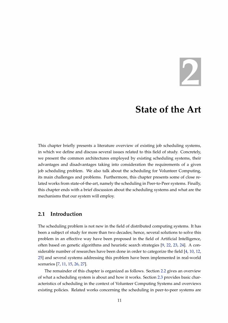
The scheduler has the responsibility of selecting resources and scheduling jobs in sucha way that user and application requirements are met, in terms of global execution time(throughput), cost of used resources and response time. Generally, a job can have thestates shown in Figure 2.1 and described in Table 2.1. The provided diagram is similar tothose diagrams of state transition of a process, found in many classical operating systems’
12
2. STATE OF THE ART 2.2. Job Scheduling System
Submitted Ready Scheduled Running
Aborted
Suspended Cancelled
Terminated
Figure 2.1: The states of a job.
central scheduler
jobs
job1job2
job3
node2node1 node3
Figure 2.2: Centralized scheduling architecture. Adapted from Li et al. [36].
books, for example in [29, 30, 31], or found in [32, 33, 34]. Note that a job goes into Sub-mitted, Suspended or Cancelled state by a user’s action while the remainder transitionsare triggered by the scheduling system.
2.2.1 Scheduling Architectures
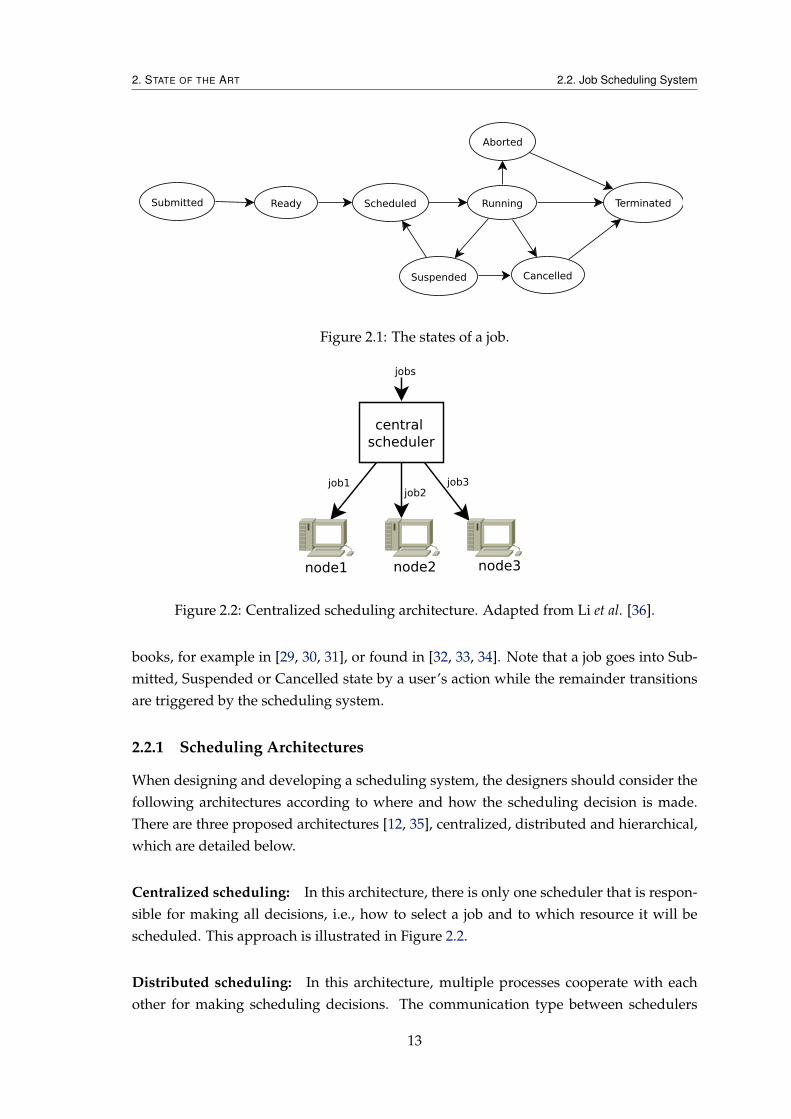
When designing and developing a scheduling system, the designers should consider thefollowing architectures according to where and how the scheduling decision is made.There are three proposed architectures [12, 35], centralized, distributed and hierarchical,which are detailed below.
Centralized scheduling: In this architecture, there is only one scheduler that is respon-sible for making all decisions, i.e., how to select a job and to which resource it will bescheduled. This approach is illustrated in Figure 2.2.
Distributed scheduling: In this architecture, multiple processes cooperate with eachother for making scheduling decisions. The communication type between schedulers
13

2. STATE OF THE ART 2.2. Job Scheduling System
localresources
localresources
localresources
localresources
scheduler1
scheduler3 scheduler4
scheduler2
jobs
jobs
jobs
jobs
jobs
jobs
(a) Distributed scheduling with direct communication between sched-ulers.
localresources
scheduler3
scheduler1
scheduler2
jobsjobs
jobs
jobs jobs
jobs
Job pool
localresources
localresources
(b) Distributed scheduling with indirect communication be-tween schedulers via job pool.
Figure 2.3: Distributed scheduling architectures. Adapted from Li et al. [36].
can be divided in two sub-types [36], namely (1) direct communication and (2) indirectcommunication via job pool. In (1) each scheduling process features a list of it peersto whom it can communicate with. When it cannot schedule a given job locally then itsends the job to other schedulers as shown in Figure 2.3(a), whereas in (2), illustratedin Figure 2.3(b), when a job cannot be locally scheduled, then it is placed on a job poolto be scheduled by other and therefore the schedulers’ policies should ensure that allsubmitted jobs to the job pool eventually will be executed.
Hierarchical scheduling: In this approach, jobs are submitted to a central node, whichdispatches them to local schedulers, whereas each local scheduler submits jobs to its com-puting resources. Figure 2.4 depicts this approach.
In Table 2.2, we summarize the advantages and disadvantages of each schedulingarchitecture.
14

2. STATE OF THE ART 2.2. Job Scheduling System
localresources
central scheduler
localscheduler1
localscheduler2
jobs
jobs jobs
localresources
Figure 2.4: Hierarchical scheduling architecture. Adapted from Li et al. [36].
Architecture Advantages Disadvantages
Centralized - Makes better scheduling deci-sions because the scheduler hasaccess to all information aboutall resources.
- Single point of failure;- Does not scale well with the in-creasing of number of resources.
Distributed - Scalable;- Can offer better fault toleranceand reliability.
- The lack of a global scheduler,that knows all system informa-tion, may lead to sub-optimalscheduling decisions.
Hierarchical - Global scheduler and localscheduler can have differentpolicies in selecting jobs or re-sources.
- The central scheduler can havescalability and communicationbottlenecks because it is a sin-gle instance to which all jobs arefirstly submitted.
Table 2.2: A summary of advantages and disadvantages of centralized, distributed andhierarchical scheduling.
2.2.2 Resource Discovery
The resource discovery consists in finding suitable resources from an available set ofthem, for executing jobs. The information that is passed from resources to the schedulerare CPU speed and current load, available memory, etc. The resource discovery might beperformed by three models, i.e., the pull model, push and push-pull, as proposed by Liet al. [36].
The pull model: A daemon process associated with the scheduler is responsible forrequesting/pulling state information from resources. Figure 2.5 depicts this model.
The push model: In this model, the process of resource discovery is started by resourcesthemselves, i.e., each resource has a local daemon that collects and pushes state informa-tion to the scheduler, which receives and stores it in a database for later retrieving by the
15

2. STATE OF THE ART 2.2. Job Scheduling System
daemon
scheduler
node1 node2
node information node information
Figure 2.5: The pull model for resource discovery. Adapted from Li et al. [36].
daemon daemon
Node Statescheduler
node1 node2
node information node information
Figure 2.6: The push model for resource discovery. Adapted from Li et al. [36].
scheduling algorithm. Figure 2.6 illustrates this model.
The push-pull model: This model is a combination of pull and push strategies, i.e.,there is a daemon process in the central scheduler, who pulls information from aggrega-tors, and there are daemons in nodes/resources whom collect and push state informationto the daemon process of a known aggregator, which is responsible for aggregating in-formation from a set of resources and replying queries from the scheduler. This strategyfor resource discovery is shown in Figure 2.7.
Resource discovery in distributed scheduling: Note that, the previously described re-source discovery mechanisms apply not only to the centralized but also to distributedscheduling. But usually in decentralized environments the discovery is accomplished bya central entity (e.g., the Grid Peer Information Service in [37]), which itself can be imple-mented either as centralized or decentralized. The latter case might be more challengingbecause it is necessary to keep all its replicas coherent.
2.2.3 Job Scheduling Policy
The process of selecting the next job from a queue to be scheduled is accomplished byusing a dedicated algorithm named scheduling policy.
In the context of scheduling in distributed computing systems, a policy is defined asan algorithm that determines to which resources a job is assigned [12], that is, how itshould choose a job for execution from its available set of jobs and how it should pick
16

2. STATE OF THE ART 2.2. Job Scheduling System
daemon
daemondaemon
daemon
daemon
daemon
scheduler
aggregator aggregator
node2node1 node3
node informationnode information node information
Figure 2.7: The push-pull model for resource discovery. Adapted from Li et al. [36].
up one resource to execute the chosen job, from an available set of resources. Or evenmore concrete, what is the matching job-resource that would minimize the overall jobsexecution time.
The problem of mapping jobs into distributed resources in a way that minimizes themakespan (the total execution time), has shown to be NP-complete, by a reduction fromthe Minimum Multiprocessor Scheduling [38]. What can be done is to find sub-optimalsolutions by using strategies based on heuristic search.
Choi et al. [12] classified the scheduling policy in three approaches, i.e., simple, model-based and heuristic-based.
Simple approach The common and simple strategy [12, 39] consists in selecting jobs orresources with the First Come First Serve (FCFS) method, which can be imple-mented with a well-known data structure, the FIFO (First In First Out) queue, ora random approach, which is implement by techniques of random numbers gener-ation.
Model-based This approach is divided in three main categories, namely deterministic,probabilistic or economy model.
In deterministic model, jobs or resources are selected according to a predefinedstructure or topology of their organization, that is, how the jobs or resources are in-terconnected with each other. The common structures or topologies are the queue,stack, graph and the ring. In comparison, in probabilistic model, jobs or resourcesare selected according to probability theory (e.g., using the Markov model as ap-plied in [40]).
Heuristic-based In this approach, jobs or resources are selected by ranking (i.e., ranksand then chooses the best one), matching (i.e., chooses the best one accordingto evaluation functions) and/or exclusion (i.e., excludes resources according to agiven criteria and then chooses the best one among survivors).
17

2. STATE OF THE ART 2.3. Job scheduling in Volunteer Computing Systems
There are other scheduling policies that were not mentioned above, which are thosebased on priority of jobs. Examples are pre-emptive scheduling, which lets a pendinghigh-priority job to take resources away from an executing job of lower priority, andshortest job first (SJF), in which the next job to be scheduled is the one that has minimumestimated completion time (ECT); if two jobs have the same ECT then FCFS is applied.
A well-known problem of priority-based scheduling is starvation, i.e., a job that isready to run can never be scheduled because high-priority jobs are always selected firsteven when they arrive after that job. A solution to solve this problem is to apply ageing,which is a technique of gradually increasing the priority of jobs that wait in the systemfor a long time [31].
2.2.4 Job Dispatching
It is the process of assigning the execution of next job to run on the selected resource. Itcan also be performed according to the pull and push modes [36], described as follows:
Pull mode: The resources pull jobs from scheduler when they go into idle time andthen the scheduler assigns jobs to them according to its scheduling policy. This mode issuitable for those systems where resources are volatile, i.e., non-dedicated [12, 41].
Push mode: The scheduler starts the scheduling process when jobs are submitted to itsqueue, that is, it pushes jobs to resources according to its scheduling policy. The pushmode can be suitable for systems whose the probability of a resource being in idle state isvery low (in this case, the resources are called dedicated resources as defined in [12, 41]).
An example of a scheduling system that employs similar mechanisms is the Condor[15]. It allocates resources for job dispatching by employing a matchmaking mechanism.This mechanism is based upon notion that jobs and resources advertise themselves inclassified advertising (abbreviated ClassAds), which include their characteristics andrequirements, then each pair job-resource that matches is created.
2.3 Job scheduling in Volunteer Computing Systems
The job scheduling in VCSs has several common characteristics with Grid scheduling,but in VCSs it should be taken into consideration that the resource providers are notreliable; VC resources are dynamic (they can join and leave the system at any time), ei-ther due to the poor network bandwidth or intentionally by theirs providers; and theresources are highly heterogeneous [12]. The reliability is related with the fact that VCresources may return maliciously incorrect result [42] and they are faulty, which requiresthe implementation of result validation and fault tolerance mechanisms.
18

2. STATE OF THE ART 2.3. Job scheduling in Volunteer Computing Systems
Fault tolerance: It is a common non-functional requirement found in many computingsystems, which enables a system to work properly even if some of its part fails [43]. Inthe context this work, it can be considered as a quality attribute that tolerates resourcefailures and volatility. The rescheduling, checkpoint-restart, replication of tasks, etc., arethe common applied techniques for leading with these failures [12]. For the reschedulingtechnique, if a scheduler detects a resource failure then it reassigns the failed task toanother resource. For the checkpoint-restart, the scheduler restarts the failed task fromthe checkpoint in another resource. For the replication, a scheduler replicates a task onmultiple resources, to allow a resource to mask the failure of another.
Load balancing: In the context of VCSs, this property attempts to balance the compu-tation load among computing resources present in the system. Normally, the system’slightly loaded nodes cooperate to remove the work in heavily loaded node by exchang-ing information (periodically or on demand) about their characteristics and current CPUload. This property can be accomplished by applying the pull mode for the work stealingor the push mode for the load distribution.
2.3.1 Scheduling
Recently, many scheduling policies based on heuristics (e.g., HEFT, min-min, max-min,and so on [44]) have been proposed in the context of VCSs because the problem of opti-mal mapping of tasks to resources is NP-complete as already mentioned previously, thusthese heuristics try to find sub-optimal mapping.
The pull approach (presented in Subsection 2.2.4) is the common dispatching modeemployed by the VCSs, i.e., when volunteers go into idle state then they contact a VCjob scheduler, requesting for the jobs for the execution. As an example, the BOINC’slocal scheduling [45] employs this mode. BOINC (Berkeley Open Infrastructure for Net-work Computing) is an open source middleware system for VCSs [13] used in several VCprojects (e.g., SETI@home [7], FightAIDS@home [27], Folding@home [26], etc.).
As stated by Estrada et al. in [9], existing job dispatching policies in VC projects can beclassified in two classes, i.e., naive and knowledge-based. Examples of naive approachesare FCFS, the random allocation and the locality assignment in which jobs are assignedpreferentially to volunteers that already have necessary data to accomplish the execution.In contrast, knowledge-based approach takes into account the historical behaviour of thevolunteers when assign jobs to them.
In contrast to the manually designed scheduling policies, which are limited to the spe-cific projects, or to those randomly generated, Estrada et al. [9] in their research entitled ADistributed Evolutionary Method to Design Scheduling Policies for Volunteer Computing, pro-posed an evolutionary method to automatically generate scheduling policies based onthe volunteers’ behaviour, when the computing resources request the jobs for execution.
19

2. STATE OF THE ART 2.4. Peer-to-Peer Approach to Scheduling
This method includes a genetic algorithm in which the representation of individuals, fit-ness function, and genetic operators are tailored to get effective policies that are project-independent, minimize errors, and maximize throughput in VC projects. However, someinput values to the algorithm are manually introduced and they intend to automate thisprocess in future work.
In [43], Lee et al. addressed the problem of robust task scheduling in VCSs by propos-ing two heuristics, which identifies best task-resource matches in terms of makespan androbustness. Generally, the robustness is defined as the capacity to function properly invariable conditions. As the context of the research was VCSs, the definition of robustnesswas narrowed down to the ability to ensure the quality of a schedule in spite of a certaindegree of performance fluctuations, such as inaccurate estimative of task completion timeand resource performance degradation. For a given schedule, both proposed algorithms,RMAX and RMXMN, aim to reschedule it, if a new task-resource match improves therobustness without increasing the makespan.
Extensive set of experiments allowed to conclude that the robustness of output sched-ules is improved by maximizing either the total or minimum relative delay time over allallocated VC resources.
2.4 Peer-to-Peer Approach to Scheduling
This section overviews two related works concerning the scheduling in P2P1 systems.The reason why we are presenting these systems, is because we intend to developed adistributed job scheduling where each node can provide both client and server function-alities.
Cao et al. [37] in their research entitled A Peer-to-Peer Approach to Task Scheduling pro-posed a P2P approach which employs the distributed scheduling architecture to lessenthe load of intermediate server by letting the peers to cooperate among them to makescheduling decisions using their own scheduling policies. Each scheduler running on apeer follows a generic architecture which authors denominated PGS (P2P Grid Sched-uler) and jobs are firstly submitted to the local scheduler where they originated. Eachpeer interacts with GPIS for collecting information about other peers and making schedul-ing decisions. Once a scheduler has decided to/from which peer it should dispatch/re-quest jobs, then starts to interact directly with it through Peer Communication compo-nent.
The system relies on a Grid Peer Information Service (GPIS) based on Grid Informa-tion Service (GIS2). The GPIS provides information about peers in the system and it is ameta-data infrastructure that enhances existing GIS in Grid middleware. As the authorsstated, in Grid environment the GIS gets outdated very quickly, because nodes are freely
1The term peer-to-peer (P2P) refers to a class of systems and applications that employ distributed re-sources to perform a function in a decentralized manner [46].
2GIS is a software component, either centralized or distributed, that maintains information about services,computing resources in computational grid, etc., and makes that information available when inquired [47].
20

2. STATE OF THE ART 2.4. Peer-to-Peer Approach to Scheduling
GPIS
Dispatcher
SystemMonitor
Scheduler Reporter
Enquirer
Process Monitor
CollectorExecutionqueue
ApplicationCommunication
GridCommunication
PeerCommunication
Task
Grid
PGS
Figure 2.8: The architecture of PGS. Adapted from Cao et al. [37].
to join and leave at any time, and due to possible system failures. Figure 2.8 illustratesthe PGS architecture installed on every peer. The components that compose the PGS arethe following:
Grid Communication It is a communication interface between GPIS and PGS’s compo-nents to allow a peer to query information about other peers kept by GPIS.
Application Communication It is an interface to enables user to provide resource de-tails, to edit GPIS and specify scheduling policies.
System Monitor It is responsible for gathering quality information (either periodicallyor on the demand) about a peer (i.e., CPU load, available RAM, etc.) and translatingit into readable format to be used in resource selection process.
Scheduler The component responsible for scheduling tasks of submitted jobs, by re-questing a group of peers from the GPIS and consulting the System Monitor toget peer information, and according to the scheduling policy it decides if a task willbe executed locally or remotely.
Dispatcher It is responsible for dispatching tasks of a job to other peers when peer isbusy.
Collector It is responsible for requesting tasks from other peers when the peer go intoidle time.
21

2. STATE OF THE ART 2.5. Scheduling of Interdependent Tasks
Process Monitor The component responsible for monitoring the tasks that are being ex-ecuted locally.
Reporter It is responsible for gathering the tasks’ status from Process Monitor wheninquired by other peers.
Enquirer The component responsible for requesting tasks’ status information from re-mote peers.
The process of scheduling in PGS is composed by peers registration in GPIS, taskscheduling and task execution. The task scheduling is divided in task capturing and taskdispatching. Task capturing uses push mode, whereas task dispatching employs pullmode.
The proposed architecture was implemented and the performed experiments allowedto conclude that combination of push and pull modes for task dispatching achieved fasterconvergence in speedup than only push mode.
Zhao et al. [18] proposed a system named PPVC: A P2P Volunteer Computing System,for job scheduling, in which volunteers are organized as a P2P network, i.e., there is nocentral server and every volunteer has the same functionality.
In order to use several computers in the network, a job should be able to be recursivelyseparable into small sub-jobs. When a peer receives a job, he splits it in N + 1 sub-jobs,where N is the number of its neighbours that are free. One sub-job is executed locally andremaining will be sent to N free neighbours. A job is split until not possible to be splitany more or if a peer has no available neighbour. When a peer completes the executionof a job, the result is sent to its parent to be collected and merged with other results. Thesystem supports the dynamic joining and leaving of peers, by self-reorganization of itsgrid.
The authors implemented the PPVC using Java platform and the case of study wasN-Queen problem. The experiments were conducted by using three computers and theresults shown that the efficiency in terms of system’s response time with three peers, for14-Queen was 87.5%, 15-Queen was 88.1% and 16-Queen was 89.9%, respectively.
2.5 Scheduling of Interdependent Tasks
Relatively to scheduling tasks with dependencies, it was found that they can be modelledwith a Directed Acyclic Graph (DAG) [21, 23, 43, 48, 49, 50, 51, 52], where each noderepresents a task, the data dependency between two tasks is represented by an edgeand in some cases a weight on an edge represents the cost in terms of time to transferinformation (e.g., data, code, etc.) from one task to another.
22

2. STATE OF THE ART 2.5. Scheduling of Interdependent Tasks
Blythe et al. [50] proposed two classes of resources allocation algorithms: task-basedapproach (TBA) and workflow-based approach (WBA). The jobs/tasks in a workflowhave well-defined dependencies of required input data to allow the computing. TBAgreedily assigns each ready to run task to a resource regarding only the informationabout that task, i.e., it only reasons about the tasks that are ready to run at any given timeinstant, whereas WBA searches for an efficient allocation of entire workflow, and mayrevise the allocation of a task based on subsequent tasks. The performed simulations al-lowed the authors to conclude that both approaches are suitable for computing-intensiveworkflows but WBA is more suitable for data-intensive workflows because it decreasesthe time to transfer data from one task to another.
Moise et al. [21] proposed a scheduling algorithm named CoAllocation, for schedulingtasks having dependencies, which is a decentralized, dynamic and optimal mechanismfor job scheduling in Grid environments. CoAllocation consists in allocating tasks hav-ing dependencies, in which the main purpose consists in generating schedules in efficientway, in terms of load balancing among computing resources and minimum time for exe-cution of tasks. Tasks and computing resources are described by using the XML format.
A set of tasks is represented with a weighted DAG, in which each node represents atask and the dependency between two tasks is represented by an edge. A weight on edgemeans the cost in terms of time to transfer information between two tasks and a weighton a node is the cost in terms of time to execute a task.
The CoAllocation algorithm involves two types of entities, called broker and agent,defined as follows:
Broker This entity is responsible for receiving an XML file containing tasks’ dependen-cies from a user, clustering of tasks and distributing each formed cluster to eachagent.
Agent It is an entity responsible for managing a set of local computing resources.
The CoAllocation algorithm comprises three phases, which are described below:
Task clustering This phase consists in creating a DAG of sub-DAGs of tasks having de-pendencies, on which each a sub-DAG is connected to another if there is a depen-dency between one of its tasks and another tasks of other sub-DAG.
Dynamic scheduling inside a cluster (i.e., a sub-DAG) It consists in scheduling tasks toan agent’s local computing resources.
Dynamic scheduling of clusters It is the final scheduling, that will be done by the bro-ker, of the DAG of clusters based on the dependencies between them.
The proposed algorithm was tested and experimental results have shown that loadbalancing goal was met. However, the authors did not specify if their implementation of
23

2. STATE OF THE ART 2.6. Discussion
the broker is centralized or distributed, i.e., if the broker is centralized then it is a singlepoint of failure.
2.6 Discussion
Throughout the previous sections, we have presented what is a job scheduling system,how it works in the context of distributed systems and particularly in the context of Vol-unteer Computing Systems. We also presented what are the challenges and problemsraised by these kinds of systems.
Since we intend to develop a distributed task scheduling where each node may havethe role of task producers, by submitting workflows for execution, and task consumers,by donating CPU cycles, then the distributed scheduling architecture with direct commu-nication (presented in Subsection 2.2.1) better fills our requirements, in comparison withcentralized or hierarchical scheduling. The scheduling policy which will be employed isthe priority-based FCFS.
The inter-dependencies between ATs may be modelled with a DAG and the systemwill schedule only ready-to-run tasks, i.e., the tasks that satisfy all required conditions tobe scheduled.
To automatically ensure the load balancing property, the pull mode, defined on Sub-section 2.2.4, will be applied by resources for requesting jobs when their CPUs come intoidle state. Also, the push mode may be applied when first jobs are submitted to the sys-tem. The fault tolerance mechanism will be the reassignment, explained in Section 2.3.
24

3The Distributed Execution Platform
This chapter describes the requirements that the system to implement must satisfy, byexploiting idle CPU cycles of existing computing resources within the company’s LAN,to execute automatic tasks of PLMI2 application, taking into account the well-defined de-pendencies among them. We also define the overall system architecture and establish thecommunication protocols among its several entities, in order to support the schedulingof the computation in the distributed environment.
3.1 Requirements
Albatroz Engineering aims to have a workflow execution engine able to schedule theautomatic tasks from the PLMI2 application among the multiple desktops available inthe local network, according to a volunteer-based work distribution strategy. This systemshould be efficient, scalable, and at the same time, resilient to both network and nodefailures.
For instance, suppose that one operator requests the scheduling of four tasks to beexecuted by a server located in a given host and subsequently this host is turned off.Then, if there is at least one another server located in other host, the system should ensurethat these tasks will be executed.
Actually, the company has between twenty and thirty hosts available for data process-ing, and usually only between five and ten hosts are used by lines inspection operatorsto process inspections’ data. The company’s PLMI2 application does not support fault-tolerance of tasks execution. For instance, if an operator requests the execution of fourtasks with dependencies and immediately he turns off his workstation then all four taskswill be lost because the tasks are executed only by a single host, that is, by the host where
25

3. THE DISTRIBUTED EXECUTION PLATFORM 3.2. Overall Architecture
ID Description Priority
FR1 It must be built a distributed system able to exploit idle computing time from work-stations, to schedule and execute automatic tasks of PLMI2 application.
MUST
FR2 It must be possible to establish the well-defined dependencies among tasks. MUSTFR3 It must be possible to distinguish an interactive from batch task. MUSTFR4 Enable a client application to request the scheduling, cancelling and subscription of
task execution.MUST
FR5 Design and implement User Interfaces for client applications. SHOULD
Table 3.1: List of functional requirements
they were generated. The company would like to have a system where operators canrequest the executions of tasks on a host and if this submission host is busy (e.g., its CPUis highly loaded) then those tasks can be executed by one of another hosts located in thelocal area network (LAN). In this way, the time that lines inspection operators wait forAT results to be available, could be minimized.
The aim is to install a server application in every workstation, even if the latter is notdedicated to process the inspection data because a server is supposed to exploit only idlecycles from hosts’ CPUs to execute the tasks and also it is supposed to not decrease thehost performance given that the user may be using the workstation to carry other duties.However, in case of a server located in the submission host, if a task has a high prioritythen it should be executed there (if there is no other task currently being executed by it),even if its CPU load is not low because in such case the operator wants to get the task’sresults immediately.
Taking into consideration these scenarios, we propose a new distributed task schedul-ing system where each node may have the role of producer and consumer. Coming todetails, this means that a node may generate tasks to be executed by the remainder nodes,or, when idle, contribute with its computing resources to the Volunteer Computing, be-coming a consumer.
To meet such requirements, we opt for a distributed scheduling architecture withdirect communication (already presented in Section 2.2.1) in comparison with the cen-tralized or hierarchical scheduling, since it may provide scalability, better fault-tolerancemechanisms and load-balancing among schedulers/servers.
Concretely, we summarize these requirements as functional and non-functional, pre-sented in Table 3.1 and Table 3.2, respectively, according to the MoSCoW1 prioritisationmethod.
3.2 Overall Architecture
The general overview of the system’s architecture that we propose is shown in Figure3.1, where all hosts are interconnected by the company’s LAN, on which the role of eachcomponent is defined as follows:
1https://en.wikipedia.org/wiki/MoSCoW_method
26

3. THE DISTRIBUTED EXECUTION PLATFORM 3.2. Overall Architecture
ID Description Priority
NFR1 The system should be efficient and scalable, i.e., it only provides added value if itsglobal execution time is less than of the existing solution.
MUST
NFR2 Fault-tolerance of task execution – the failure of a server-node should not cause thesystem to behave incorrectly.
MUST
NFR3 Non-intrusive – the performance of the workstation where a server is running,should not be lower if it is not running a task. The server should be lightweightwhen not running a task.
SHOULD
NFR4 Heterogeneity – the system should work in the LAN which has heterogeneousworkstations (different CPUs, RAM, operating systems, etc.).
SHOULD
Table 3.2: List of non-functional requirements
client-application This component represents a generic client-application, that is, it maybe either a command-line client (e.g., Telnet) or Graphical User Interface (GUI)clients. Firstly, it should be able to request a server-node (local or remote) to sched-ule the execution of a task. Secondly, it must be able to request the cancellationof a running task and also subscribe its interest in getting a given task’s progress.Moreover, it may also run in the same host (local) as the server-node, as illustratedin Figure 3.1, i.e., the cases where ca (client-application) and sn (server-node) areinside the same rectangle shape. Local means that the server and client are runningin the same host, and remote in different hosts.
server-node This component is responsible for making scheduling decisions, such astask dispatching by communicating with other servers/schedulers. The selectednode for executing a given task (t) launches the executable of t and opens a com-munication channel between both to monitor the evolution of the t’s execution. An-other responsibility of a server-node, is to report, to interested parties, the progressof the task currently in execution. It should be stated that a server-node may sup-port connections with multiple client-applications at the same time and it is notrequired to be connected with any client-application.
Database server This component stores the results generated by the execution of a taskby a server-node. A result is a dataset generated by a task and it is identified by adatabase relation primary key.
task It represents the execution an automatic task of PLMI2 application. The PLMI2tasks were, up to now, integral parts of PLMI2, and now for the purposes of thissystem they have to be independent applications. Therefore, when a task is start-ed/launched by a server-node then it may read input datasets from the Databaseserver and should generate output datasets in this same database.
Upon the completion of a task t, the hosting server-node is responsible for assigningthe identifiers of output datasets to all tasks whose inputs depend on the outputsof t.
27

3. THE DISTRIBUTED EXECUTION PLATFORM 3.2. Overall Architecture
Figure 3.1: A general view of proposed system architecture.
The devised architecture comprises three distinct entities, i.e., the client-application,the server-node and the running task. In order for these to communicate, protocols haveto be established.
Due to the lack of a centralized entity in the system architecture, it is in fact a dis-tributed protocol among server-nodes, and in order to meet this requirement it is nec-essary to have distributed algorithms for ensuring that all nodes will have a consistentview of the system’s state.
Therefore, all system components should agree on the protocols defined here, in sucha way that each one of them can understand each other and cooperate to achieve thecommon goal, which is the execution all the scheduled tasks.
The communication among the system’s entities is achieved by exchanging messagesand a message may contain several pieces of information. For instance, when a server-node receives a message from another server-node or from a client-application, then ittriggers an appropriate action to process the received message and according to the kindof the message it makes some local decisions and may change its state, and additionallyit may reply back to the message sender.
In the remainder of this chapter, we begin by explaining how tasks are uniquely iden-tified during their lifetimes and the content of a task, in Section 3.3. In Section 3.4 to 3.6we, respectively, specify the communication protocol between a client-application and aserver-node, between a server-node and a running task and the protocol among server-nodes.
28

3. THE DISTRIBUTED EXECUTION PLATFORM 3.3. Task Identification and Contents
3.3 Task Identification and Contents
A task needs to be uniquely identified during its lifetime in the system. The best waywe found to do this was by using the Universally Unique Identifier (UUID) specified byIETF RFC 4122 [53], which allows the generation of unique identifiers, across space andtime, in distributed environments without a centralized coordinator.
A task has the following properties:
1. A Universally Unique Identifier (UUID);
2. The associated executable file name;
3. The number of input datasets required to be assigned for it to become a Ready task;
4. The identifier of the client-application’s host which ordered its execution;
5. A state, which may be Submitted, Ready, Running, Terminated or Cancelled;
6. A priority, which can be low or interactive. The priority interactive is privileged overthe low;
7. A timestamp registering when it was submitted to the system;
8. The hostname of the server-node which scheduled it;
9. The hostname of the server-node where it is running, if its state equals Running;
10. The required identifiers of input datasets;
11. The identifiers of output datasets.
3.4 Communication: Client-application↔ Server-node
In this section we describe the interaction protocol between a client-application and server-node, for each operation offered by the system to client-applications, i.e., the schedul-ing of a task, cancellation of a task execution and, subscription of interest in getting theprogress and state of a task. For these three operations, the interaction follows a requestreply-reply pattern that is always initiated by the client. Additionally, the server, period-ically sends the progress of the tasks over which the client has revealed its interest.
This communication protocol consists of seven kinds of messages, described in Table3.3. In case of the SCHEDULE message, when a client-application requests the schedul-ing of task ty which has an input i that depends on the nth output of a task tx then itshould send the argument
−a task_uuid_x nth_output_x
to inform the server-node how to assign the required identifier of output dataset (the nth
output) to i, when tx terminates the execution.
29

3. THE DISTRIBUTED EXECUTION PLATFORM 3.4. Communication: Client-application ↔ Server-node
Message Parameters Description
SCHEDULE task_exec_name priority [-ppath_to_raw_files] [-a task_uuid_1nth_output_1] ... [-a task_uuid_nnth_output_n] [-x parameters_file]
Allows a client-application to request aserver-node to schedule the execution ofan automatic task.
SUBSCRIBE task_uuid_1 ... task_uuid_n Allows a client to subscribe its interest ingetting the progress and state of a set oftasks.
CANCEL task_uuid Allows a client to request a server to cancelthe execution of a task.
SCHEDULED task_uuid A server-node notifies a client-applicationthat a given task was scheduled.
SUBSCRIBED task_uuid_1 ... task_uuid_n A server notifies a client that its subscrip-tion to a given set of tasks was registeredsuccessfully.
CANCELLED task_uuid A server notifies a client that a given taskwas cancelled.
PROGRESS task_uuid percent-age_of_work_performed state
A server sends the progress of a runningtask to all clients that subscribed this task.
ERROR message A server-node notifies a client-applicationthat its request was not successfully pro-cessed.
Table 3.3: Format of the messages exchanged between a client-application and server-node.
SCHEDULED task_uuid
SCHEDULE task_name priority [optional params]
client-application server-node
orERROR msg
Figure 3.2: Schedule an automatic task (client-application↔ server-node).
The options of the SCHEDULE message are:
−a Indicates one of arguments of ty. An argument is composed by the UUID of a task tx
on which ty depends on and the nth output of tx.
−x Indicates that a parameter file (an XML) was provided.
−p Indicates that a file system path or a location within the LAN containing the raw datafiles was provided.
Just to illustrate how it works, suppose that a client-application ca wants to schedulean automatic task t. Then this protocol enables ca able to pass only the required argu-ments to t.
30

3. THE DISTRIBUTED EXECUTION PLATFORM 3.4. Communication: Client-application ↔ Server-node
SUBSCRIBE task_uuid_1 ... task_uuid_n
client-application server-node
SUBSCRIBED task_uuid_1 ... task_uuid_n
or ERROR msg
Figure 3.3: Subscribing interest in getting the progress and state of a set of tasks (client-application↔ server-node).
PROGRESS task_uuid percentage state
client-application server-node
Figure 3.4: Progress reporting (server-node→ client-application).
The protocol for enabling a client-application to request the scheduling of a task isillustrated in Figure 3.2, on which any argument inside a square brackets means optional.If the server-node was able to schedule the task then it generates and sends the taskunique identifier to the client. Else, it replies with an error message describing why itwas not possible to schedule the task.
Figure 3.3 depicts the interaction protocol for a client-application to request its sub-scription in getting the progress and state of a set of tasks, identified by task_uuid_1 untiltask_uuid_n. If the server-node has processed its request successfully then it confirms.Else, if it has found some error while processing the request then it sends an error mes-sage describing what happened.
Figure 3.4 shows the interaction protocol, in which a server-node sends the progressand sate of a given task identified by task_uuid to a client-application, being the latterpreviously subscribed its interest in task_uuid.
Finally, this section ends with Figure 3.5, which illustrates the protocol for a client-application to request the cancellation of a given task, identified by task_uuid. If theserver has cancelled the task then it confirms the cancellation to the client-application.Otherwise, it notifies the client with an error message explaining what happened.
31

3. THE DISTRIBUTED EXECUTION PLATFORM 3.5. Communication: Server-node ↔ Running Task
CANCELLED task_uuid
CANCEL task_uuid
client-application server-node
orERROR msg
Figure 3.5: Cancelling the execution of a task (client-application↔ server-node).
Message Parameters Description
PROGRESS percentage_of_work_performed A running task sends its local server the currentprogress of a running task.
CANCEL A server requests a running task to cancel the exe-cution of a task.
TERMINATED id-dataset-1 ... id-dataset-n A task notifies a server that it has completed its theexecution, where the id-dataset-n is the nth identi-fier of output dataset generated on database by thetask execution.
CANCELLED A task notifies the server that it has cancelled itsexecution.
ERROR message Message sent from a running task to the server-node, if some error has happened while it was pro-cessing the latter’s request.
Table 3.4: Format of the messages exchanged between a server-node and a running task.
3.5 Communication: Server-node↔ Running Task
The communication between a server-node and a running task may be initiated by eitherentities. Server-node initiated communication has the sole purpose of cancelling the exe-cution of the task, whilst task initiated communication has the purpose of reporting thetask’s execution progress.
Table 3.4 presents the format of messages exchanged between a server-node and arunning task. The messages that not have any parameter, means that either it is not re-quired or else the only parameter needed is the identification of the message sender (e.g.,its IP address), which we assume that is extracted/retrieved by the message receiver.
The protocol for a running task to report its progress to the server-node is depictedin Figure 3.6. The protocol for a running task to report the final results of its executionto the server-node is presented in Figure 3.7. The protocol for a server-node to request arunning task to cancel its execution is shown in Figure 3.8.
32

3. THE DISTRIBUTED EXECUTION PLATFORM 3.6. Communication: Server-node ↔ Server-node
server-node running task
PROGRESS percentage
Figure 3.6: Progress reporting (running task→ server-node).
Figure 3.7: Reporting the final results of a task (running task→ server-node )
3.6 Communication: Server-node↔ Server-node
Every server-node has a local state, mainly composed by two data structures: a mapstoring all tasks currently under the system’s supervision and the queue of ready-to-runtasks. Given that the system is purely distributed, the server-nodes have to coordinatethemselves in order to ensure that each of one of them has a consistent view of this state.However, we do not want to impose a strong consistency model that requires a synchro-nization among server-nodes for every operation performed on these data structures.Accordingly, we opt for a more relaxed approach with eventual consistency properties.As such, each server-node will update its state, based on the type and contents of themessages that it receives. When an inconsistency is detected by a server-node, then it ap-peals to a special server-node, which we denominate master, to deliver it the most recentstate of the data structures.
In the next two subsections, we provide a comprehensive explanation of two dis-tributed algorithms run by every server-node, namely the master election and the dis-tributed scheduling algorithms. The communication model for these two algorithms, aswell as the almost communication in the system, is based on the 1 to N approach, on topof a broadcasting protocol, instead of request-reply model. The motivation is to avoid, asmuch as possible, synchronization points among server-nodes.
33

3. THE DISTRIBUTED EXECUTION PLATFORM 3.6. Communication: Server-node ↔ Server-node
server-node running task
CANCEL
CANCELLEDorERROR msg
Figure 3.8: Cancelling the execution of a task (server-node↔ running task)
3.6.1 Master Election
Firstly, we have to state that our system does not have a master by default; it is electedby a consensus algorithm among server-nodes, i.e., the nodes that belong to the systemat the time of the election.
Every server-node has a reputation assigned, which indicates how many times it hasfailed, terminated or crashed. This information is used to elect the current master - thegreater is the number of times a server-node has failed, the lower is its reputation. Thisreputation is initialized with basis on a number loaded from a stable configuration file,whenever the node starts running. It is also decremented each time the node re-joins thesystem because we assume that it is recovering from a failure/crash. In the first time thata node starts up its reputation is not decremented.
This approach is similar to the Elect Lower Epoch presented in the book entitled In-troduction to Reliable and Secure Distributed Programming on page 77 [54], where the leader(in our case the master) is the process that has failed fewer times.
The need for a special node to act as the delivery of the system’s state to the newjoining nodes, or send a given task to a node when requested, came from the fact that ifwas any node to perform these operations, may be it would not have the recent system’sstate. The master is elected as being mainly the older node in system. Therefore, itsprobability of having the most recent system’s state is greater than or equals to the othernodes.
For the definition of master election protocol, the format of the messages presented inTable 3.5 are added to the system. Some of the messages do not have parameters becausein such cases they are either not required or the only parameter needed is the identifierof message sender (e.g., the IP address), and we assume that the receiver is able to extractthis identifier when it receives a message.
The master election is presented in Algorithm 3.1 and it works as follows. Upon thereception of a START_NEW_MASTER_ELECTION message, by the procedure on recep-tion of SNME(...), on a server-node from one of its counterparts notifying that they mustelect a new master then it makes its candidacy by broadcasting the TRY_TO_BE_MASTER
34

3. THE DISTRIBUTED EXECUTION PLATFORM 3.6. Communication: Server-node ↔ Server-node
Message Parameters Description
WHO_IS_MASTER Used by a new server when itcomes into the system, for ask-ing other server-nodes for themaster-server’s information.
START_NEW_MASTER_ELECTION A server-node notifies otherservers that they should start anew master-server election.
TRY_TO_BE_MASTER my_reputation local_map.sizetimestamp
A server proposes its proposalto be the master-server on anelection.
NEW_MASTER The master-server sends its in-formation to a server whenasked or to all servers when itwins an election.
Table 3.5: Format of the messages used in the master election.
message (line 6) to all. A candidacy is composed by the node’s reputation, the number oftasks on its local map and a timestamp registering when the candidacy was generated.Within a given waiting time-window (line 7) of 10 seconds, whenever a server-node re-ceives a candidacy from another server then he inserts it in a priority queue of candi-dacies ordered by candidacy’s timestamp (see the procedure on reception of TTBM(...)).The algorithm stores the received candidacies in a priority queue ordered by the candi-dacy’s generation timestamp on its candidate because we want a server to process thesecandidacies by their emissions’ order. When this time-window finishes then it processesall received candidacies.
A server wins the election if its own candidacy is better than those ones received,meaning that if it has the highest reputation, or in case of a tie, if the number of taskson its map is greater than the remainder candidacies, or in case of a new tie, then if itscandidacy’s timestamp is older than the remainder candidacies, or again in case of a newtie, then if its host name is alphabetically lower than the remainder ones.
At the end of the algorithm, if the server has won the election then it broadcasts amessage to all nodes notifying the winning. Else, if it has lost then it will receive the newmaster information.
In Figure 3.9 is shown an example of an interaction protocol in which the server-node labelled as sn1 wins the election, supposing that it has the highest reputation. TheTASKS_TRANSFER message that appears in this figure is later introduced in Section3.6.3.
3.6.1.1 Fault-tolerance
Our system aims to provide the supporting for fault-tolerance at server-node and net-work level. Taking this aspect into consideration and the fact that a master is one ofserver-nodes, then the system should support fault-tolerance for it.
35

3. THE DISTRIBUTED EXECUTION PLATFORM 3.6. Communication: Server-node ↔ Server-node
Algorithm 3.1: Master ElectionData: // Required variables.
1 bool Did_I_Win_The_Election;// Whether this server has won the election or not.2 int my_reputation;// The server reputation loaded from a stable configuration file.3 string my_hostname;// The name of the server’s host.4 bool Am_I_Master;// Whether this server is the master or not.5 time my_TTBM_timestamp;6 map<uuid, task> local_map;7 priority_queue<TRY_TO_BE_MASTER_Request>TRY_TO_BE_MASTER_requests_queue;
8
Procedure on reception of TTBM( TRY_TO_BE_MASTER reputation map_sizetimestamp)1 TRY_TO_BE_MASTER_requests_queue.push(TRY_TO_BE_MASTER_Request(timestamp,
peer_hostname, reputation, map_size));
9Procedure on reception of SNME( START_NEW_MASTER_ELECTION)1 trigger elect master();
10
Procedure elect master()1 begin2 Did_I_Win_The_Election← true;3 TRY_TO_BE_MASTER_Request req← null;4 Am_I_Master← false;5 my_TTBM_timestamp← time();6 broadcast TRY_TO_BE_MASTER my_reputation local_map.size timestamp;7 wait for a given time-window for another servers to make their candidacies;
// Process TRY_TO_BE_MASTER messages received from other servers/peers.8 while not TRY_TO_BE_MASTER_requests_queue.empty() do9 req← TRY_TO_BE_MASTER_requests_queue.pop();
10 if req.reputation > my_reputation then11 Did_I_Win_The_Election← false;
12 else if req.reputation = my_reputation then13 if req.map_size = local_map.size() then14 if req.TTBM_timestamp < my_TTBM_timestamp then // Did the peer send
TRY_TO_BE_MASTER first than me?15 Did_I_Win_The_Election← false;
16 else if req.TTBM_timestamp = my_TTBM_timestamp then17 if req.peer_hostname < my_hostname then18 Did_I_Win_The_Election← false;
19 if Did_I_Win_The_Election then20 Am_I_Master← true;21 broadcast NEW_MASTER; // Notify the peers that this server is the new
master.
36

3. THE DISTRIBUTED EXECUTION PLATFORM 3.6. Communication: Server-node ↔ Server-node
joiningmsn
sn2
sn1
WIMm->mWHO_IS_MASTER,mSNMEm->mSTART_NEW_MASTER_ELECTION,mTTBMm->mTRY_TO_BE_MASTER,NMm->mNEW_MASTER,mTTm->mTASKS_TRANSFER
WIM
time-window
SNME TTBM
TTBM
TTBM
time-window
time-window
time-window
NM
(reputation = -1)
(reputation = 10)
(reputation = 5)
TT
TTBM NM
Figure 3.9: An illustration of master election protocol.
Server-node level: If the master server-node fails then the remainder nodes shouldeventually detect this issue and elect a new one, according to the Algorithm 3.1. Thesystem detects the failure of the master-server when a node receives a PROGRESS mes-sage of a given task that it does not have on its local map yet then it asks the master forthis task by sending a GET_TASK message (defined later in Section 3.6.2), and the masterdoes not reply. Also, the system detects the master failure when a new node joins the sys-tem, broadcasts WHO_IS_MASTER message and no server replies. The system toleratesits failure by electing a new one.
Network level: An example of a problem that a network failure may cause is, supposethat the communication link breaks between the master and the remainder nodes. Then,the latter will assume that the master has failed and elect a new one. When the oldermaster has the communication link with the system back, there will be two masters, i.e.,the older one will behave like if it was the only one master when it is not. The aim is tohave only one master in the system at any time but this failure may cause it to have morethan one.
Although it has not been implemented, a possible way to solve this issue could beby forcing a master to broadcast its information periodically (e.g. a heartbeat message),which must contain a timestamp registering when it was elected. Each node when re-ceives this information will update who is the current master regarding the timestamp,meaning that if the timestamp of when the message sender was elected in newer than
37

3. THE DISTRIBUTED EXECUTION PLATFORM 3.6. Communication: Server-node ↔ Server-node
one from the master that it currently knows then it updates its knowledge about the mas-ter as being the sender. In case of the older master, when it receives the message fromthe newer one, it should update its local state as not being the master any more, save theinformation of the new master and stop broadcasting heartbeat messages claiming to bethe master.
Also, the above solution could be employed to solve the conflict when some messageloss has happened during the election, and due to this issue two servers may think thatboth of them won the election then they broadcast the NEW_MASTER message to all.
3.6.1.2 Properties
The master election algorithm has the following properties:
• Whenever a master is needed, or it exists at the moment or it is elected immediately;
• It ensures that if every server-node has received all proposals sent by other server-nodes, then a unique master will be elected, with basis on its tiebreaker conditions;
• In case of network partitions, it does not support conflict solving if two or moremasters are elected in different partitions, when they reconnect. A possible wayto deal with this issue can be by employing the solution previously described inSection 3.6.1.1.
3.6.2 Scheduling and Distributed Execution of Tasks
The following kinds of messages are exchanged among server-nodes in order to achievethe distributed scheduling:
ENQUEUE A server broadcasts a task to all its peers.
TRY_DEQUEUE A server notifies its peers that it is trying to remove a given task fromthe FIFO queue for the execution locally.
STATE Used by a server to notify its peers when some change happens on a task’s state.These states can be:
Running For notifying that it has started running a task.
Terminated To notify that a task has successfully executed. The message will al-ways contain the final result of a task, i.e., the identifiers of output datasetsthat were generated by the task execution.
Cancelled For informing that a task was cancelled.
PROGRESS A server reports to its peers the progress of a running task.
GET_TASK A server requests the master-server to deliver it a given task (t), identifiedby a UUID, when it receives the progress of t and it does not have t in its state.
38

3. THE DISTRIBUTED EXECUTION PLATFORM 3.6. Communication: Server-node ↔ Server-node
client-application
sn2
sn1
SCHEDULE task_name priority [optional params]
sn3
ENQUEUE task
SCHEDULED task_uuid
Figure 3.10: An illustration of the ENQUEUE protocol.
When a client-application requests a server-node to schedule the execution of a taskthen the server broadcasts an ENQUEUE message to all another servers, as illustratedin Figure 3.10. Upon the reception of an ENQUEUE message by a server, it places thecorresponding task (t) on its local map and if the t’s state equals to Ready, then t is alsoplaced in the local ready-to-run task queue.
The algorithm for the distributed dequeuing of a ready-to-run task is presented inAlgorithm 3.2 and it works as follows. Once a server enters in volunteer mode (it detectsthat its CPU has become idle) it broadcasts a TRY_DEQUEUE message to its peers, indi-cating that it wants to execute the next task in its ready-queue (line 3). This TRY_DEQUEUEoperation is followed by a waiting time-window (line 9) of 15 seconds (as it was imple-mented), which has the purpose of assessing if no server-node has concurrently issuedthe same request. If no TRY_DEQUEUE message has arrived within this window thenserver can dequeue t. A TRY_DEQUEUE message that arrives a server out of the time-window is simply ignored. The possible concurrent execution of tasks will be dealt laterin time. If one or more TRY_DEQUEUE are received for the same task, then a conflictarises and the server handles each one of them (line 11 to 15). A server loses the racefor dequeuing t if it has received at least one proposal to execute t which is lower thanits own, according to a pre-established total order relation (line 14). This order is givenby the following properties: the server proposal’s timestamp is older than the remainderproposals, or in case of a tie, then if its hostname is alphabetically lower than the otherservers’ hostnames. This total order relation is deterministic and is it computed locallyin each server.
The server-node with the lower proposal, according to the total order relation, wins tothe race to execute t. The remaining servers account (line 15) the rank of their proposals,to be used as a strategy for avoiding/minimizing the race conditions on the next timethey want to try dequeue the next task. For instance, if a server has lost the race todequeue t against two servers then on the next time it will try to dequeue the task that isin second position of the queue because its rank was 2. In this way, it will not compete
39

3. THE DISTRIBUTED EXECUTION PLATFORM 3.6. Communication: Server-node ↔ Server-node
sn1
sn3
sn2
TD -> TRY_DEQUEUE
TD Tx.uuid
time-window
Tx.uuid Running
TD Ty.uuid
TD Tz.uuid
time-window
time-window
Queue[Tx, Ty, Tz]
Queue[Tx, Ty, Tz]
Queue[Tx, Ty, Tz]
time-window
time-window
TD Tx.uuid
TD Tx.uuid Tz.uuid Running
Ty.uuid Running
Ty.uuid Running
Figure 3.11: A system configuration on which can be minimized the race conditions.
with the server that has lost the race just once (rank 1) because that server will dequeuethe task at first position of the queue. To illustrate this situation, consider the systemconfiguration shown in Figure 3.11, where it has three server-nodes (sn1, sn2 and sn3)and each one of them has three ready-to-run tasks (Tx, Ty and Tz) in the local task queue.Then suppose that all three nodes are competing to dequeue the task Tx. One of themwill win and remainder two will lose. Thus, the node which has lost the race for Tx justonce will try to dequeue Ty and the node which has lost two times will try to dequeue Tz .
Whenever a server agrees that a given node will run t or when it is notified that thet’s state became Running, then it removes t from its local ready-queue, but keeps t in themap of tasks until it receives the notification that the t has terminated its execution.
3.6.2.1 Fault-tolerance
As we have stated before in Section 3.6.1.1, we want the system to be able to supportfailure at server-node and network level.
Server-node level: Failures occurred at server-node level cause the task that eventuallywas executing at the node to fail. Thus, the remainder nodes should detect this failureand reschedule the failed task, so that it can be executed by one of the remaining server-nodes. The system notices that a node has failed/crashed during the execution of a task
40

3. THE DISTRIBUTED EXECUTION PLATFORM 3.6. Communication: Server-node ↔ Server-node
Algorithm 3.2: Distributed dequeuingData: // Required variables.
1 int rank;// The server rank in last race to dequeue a task.2 uuid try_dequeue_task_uuid;3 time timestamp_of_my_last_try_dequeue;4 string my_hostname;5 priority_queue<task> local_queue;6 priority_queue<TRY_DEQUEUE_Request> TRY_DEQUEUE_requests_queue;
7Procedure on CPU idle()1 trigger dispatch( );
8
Procedure on reception of TD(TRY_DEQUEUE task_uuid timestamp)1 TRY_DEQUEUE_requests_queue.push(TRY_DEQUEUE_Request(timestamp, task_uuid,
peer_hostname));
9
Procedure dispatch()1 begin2 if rank = 0 then3 try_dequeue_task_uuid← local_queue.top().task_uuid;
4 else5 try_dequeue_task_uuid← getTaskUUIDFromQueueAt(rank).task_uuid;6 rank← 0;7 timestamp_of_my_last_try_dequeue← time();8 broadcast TRY_DEQUEUE try_dequeue_task_uuid timestamp_of_my_last_try_dequeue;9 wait for a given time-window for messages of type TRY_DEQUEUE to arrive;
10 TRY_DEQUEUE_Request req← null;// Process TRY_DEQUEUE messages received from other servers/peers.
11 while not TRY_DEQUEUE_requests_queue.empty() do12 req← TRY_DEQUEUE_requests_queue.pop();13 if try_dequeue_task_uuid = req.task_uuid then // Conflict checking14 if (timestamp_of_my_last_try_dequeue = req.timestamp and my_hostname > req.peer_hostname)
|| (timestamp_of_my_last_try_dequeue > req.timestamp) then// Account my rank to determine which task to try dequeue on thenext call of "dispacth()".
15 rank← rank + 1;
16 if rank > 0 then // It is not the winner// The next calling of dispach() is when the CPU becomes idle again.
17 else18 broadcast STATE try_dequeue_task_uuid Running timestamp;
// Execute task.
41

3. THE DISTRIBUTED EXECUTION PLATFORM 3.6. Communication: Server-node ↔ Server-node
if the latter has stopped reporting the progress of a running task. When a task is running,its progress is sent periodically to all nodes like a heartbeat message. In Section 4.5 ofChapter 4 we present how it was implemented the fault-tolerance supporting at server-node level.
Network level: The network partition, on which the nodes of one partition cannot com-municate with other nodes located in any of the others, may cause two nodes, each onein different partitions, to start execute the same task.
To solve the above conflict scenario, when the partitions are reconnected, our imple-mentation detects that two or more nodes are running the same task and cancels theexecutions on all nodes, and lets just one node to keep running the task, according to apre-established total order function. Ideally, this function should take into considerationthe current progress of each execution, in such a way that it would let the node whichis almost completing the task execution to continue because in this way the total taskcompletion time could be decreased.
If the partitions have a delay greater than the total execution time of tasks, giventhat database is located in one of partitions, then it will be the task that has run in thatpartition which commits its results with success to the database, while other tasks willget an error when they try to connect with the database.
Nevertheless, it is very unlikely that it may happen scenarios where more than oneinstance of the same task to terminate their executions and contact the database serverwith success. If such happens, the consequence is that the database will have more thanone version of the same result. However, given this work context, it is very unlikely thatsuch scenario occurs and an analysis of cost/benefit reveals that its treatment is not apriority.
In addition to the network partition, as our system follows a distributed approach,then it is exposed to more failures. For instance, if it happens some momentary networkfailure or some delay in message delivering/transmission, i.e., if a message has arrivedout of the time-window (defined in line 9 of the Algorithm 3.2) then the nodes may startto execute the same task. This may happen because in such case, on each node the dis-tributed dequeuing algorithm will behave like if the node is the only one in the system.The implementation solves this conflict scenario in the same way as described above, thatis, by stopping the task execution at one of server-nodes and letting another to keep run-ning. But, just to recall, the scope of this thesis is within a LAN, not the Internet wherenetwork level failures may occur frequently.
3.6.2.2 Properties and assumptions
The distributed scheduling algorithm takes into consideration the following assump-tions:
• Tasks may be cancelled during their lifetimes in the system, either by an operator
42

3. THE DISTRIBUTED EXECUTION PLATFORM 3.6. Communication: Server-node ↔ Server-node
or by the system itself;
• A given task may be running at the same time in two different hosts.
And it ensures the following properties:
• Since there is at least one server-node running in the system and if such a node hasall tasks in its state and does not fail, then eventually all tasks will be executed;
• In case of two hosts executing the same task, if no network partition occurs, nor-mally, just one instance of a task completes the execution, as explained previouslyin Section 3.6.2.1;
• The algorithm is resilient to network partitions, as explained in Section 3.6.2.1.
3.6.3 Server-node Joining/Leaving
Whenever a new server-node joins the system it has to obtain the system’s state. Tothat end it begins by discovering the location of the master node by broadcasting theWHO_IS_MASTER message (defined in Section 3.6.1) to all. If no reply arrives, it as-sumes that no master is currently active and triggers the election process by broadcastingthe START_NEW_MASTER_ELECTION message (also defined in Section 3.6.1) to othernodes for notifying that they must elect a new one (which was previously illustrated inFigure 3.9).
Otherwise, if a reply arrives, subsequently the node requests the master the system’sstate. The master sends all tasks to it, by iterating its local map of tasks and for every taskit sends an ENQUEUE message directly to the node.
In addition to the WHO_IS_MASTER message, the following kind of message isadded to the system, for allowing a joining server-node to get the current system’s state:
TASKS_TRANSFER A new server requests the master-server to deliver it the currenttasks in the system.
The protocol for allowing a joining node to get the system’s state is illustrated inFigure 3.12.
Whenever a new server-node leaves the system, the remaining nodes consider thatit has failed/crashed. If it was running a task before leaving the system, then the othernodes will rescheduled that task, as explained later in Section 4.5 of Chapter 4. If it wasthe master, then when the master is needed, the election algorithm is triggered (Algo-rithm 3.1).
43

3. THE DISTRIBUTED EXECUTION PLATFORM 3.6. Communication: Server-node ↔ Server-node
Figure 3.12: Example illustrating the interaction protocol for system’s state downloadingby a joining node.
44

4Implementation
Throughout the previous chapter, we have presented what are the requirements that thesystem should meet, its distributed scheduling architecture and the communication pro-tocols among its several entities, in order to achieve the distributed scheduling. We havealso explained the distributed algorithms which implement those protocols and how thesystem supports failures at server-node and network level.
In this chapter we describe the implementation of the system prototype, which usedsome existing technologies, and we describe the architecture employed by every server-node and how the system execution log is saved persistently.
4.1 Introduction
The system was fully developed in C++11 [55] and with basis on two well-known Internetprotocols, which are the Transmission Control Protocol (TCP) and User Datagram Proto-col (UDP). Concretely, we use TCP for the communications between a client-applicationand a server-node, and UDP for communications among servers. In spite of being UDPnot reliable and not offering flow control, it is fast for local area networks (LANs) [56]and we want each server to be stateless regarding the communication with other serverslike the relation between a server and the clients in the Network File System (NFS) [57].The developed system prototype is portable for both Unix-like and Windows operatingsystems. For Unix, we use The BSD UNIX Socket Library [58] and for Windows Sockets2 API [59].
The remainder of this chapter is organized as follows. Section 4.2 briefly describesthe task interface. Section 4.3 defines a possible way for the integration of new tasksin the system. In Section 4.4, we explain how the interdependencies among tasks were
45

4. IMPLEMENTATION 4.2. Task Interface
solved and in Section 4.5 we present and describe the implementation all components ofa server-node. Finally, Section 4.6 describes how a server-node’s execution log is savedin a stable logging file.
4.2 Task Interface
As we have stated previously in Section 3.3, we use the Universality Unique Identifier(UUID) to uniquely identify a task in the system. To achieve this, our system uses theBoost C++ UUID library1, which is an implementation of UUID, for the generation oftasks’ identifiers.
To send a task t from one server-node to another, we implemented a marshal() func-tion to convert a task’s instance to its string data type representation and the bytes ofthis string which are sent to other server-nodes, are converted back to the task’s originalrepresentation by using a un-marshal() function.
Regarding the system portability, the binary files (executables) of all tasks are placedin the same working directory as the executable of the server-node application. In thisway, the server-node will use the relative path of a task instead of the absolute, whenit launches the corresponding executable. For Unix environments, as an executable nor-mally does not contain an extension associated and for Windows the .exe is the commonextension, then our task scheduling protocol imposes the client-application to send thetask executable name (the task_exec_name argument presented in Table 3.3) to the server-node. When the server-node has to start running a task in Unix, it just executes the pro-gram identified by the task_exec_name, and for Windows, it appends the .exe extension tothe task_exec_name.
4.3 Integration of a New Task in the System
To integrate a new task in our system, the server-node was implemented in such a waythat it does not have to know a task a priori, but the client-application should know andmust strictly follow the protocols defined in Section 3.4.
If a new task has to be implemented, then it will be required to specify a configurationfile which describes it (such as its type, its kinds of dependencies/inputs, etc.). The XMLprovided in Listing 4.1, can be a possible way to enable the specification of new task tobe integrated in the system.
On the client’s side a task can be simply integrated with the system, by adding itsspecification file to the client-application and on the server’s side, a task can be addedby putting its binary file (executable) in the same working directory as the server-nodeapplication.
1http://www.boost.org/doc/libs/1_55_0/libs/uuid/uuid.html
46

4. IMPLEMENTATION 4.4. Inter-tasks Dependencies
Listing 4.1: Example of task description file.1 <?xml version="1.0" encoding="utf-8"?>2 <task>3 <name>...</name>4 <type>...</type>5 <inputs>6 <input>7 <other_task_type>...</other_task_type>8 <other_nth_output>...</other_nth_output>9 </input>10 <input>11 <other_task_type>...</other_task_type>12 <other_nth_output>...</other_nth_output>13 </input>14 ...15 </inputs>16 </task>
4.4 Inter-tasks Dependencies
To solve the interdependencies among tasks, presented in Section 1.1, we use the owntasks identifiers and ordinal numbers to represent that a task depends on results of an-other, e.g., if the first input of a task tj depends on the first output of a task ti, then werepresent tj .input1 = ti.task_uuid/1st. The example in Table 4.1 illustrates this approachfor those automatic tasks presented in Section 1.1, where I, G, S and AD, represent theImport task, Georeferencing, Segmentation and Anomaly-Detection, respectively.
This representation is built internally in a server-node with basis on the task’s param-eters passed from a client-application, when the latter requests it to the schedule a task(as described in Section 3.4). In this way, a server-node is able to pass the identifiers ofoutput datasets from a terminated task to the tasks’ inputs that depend on them.
Task UUID Name Inputs
3aff3d90−2b79−11e3−8224−0800200c9a66 I Path to location with raw files
679e9490−2b79−11e3−8224−0800200c9a66 G parameters.xml
input1= 3aff3d90−2b79−11e3−8224−0800200c9a66/1st
input2= 3aff3d90−2b79−11e3−8224−0800200c9a66/2nd
input3= 3aff3d90−2b79−11e3−8224−0800200c9a66/3rd
7f850cb0−2b79−11e3−8224−0800200c9a66 S parameters.xml
input1= 3aff3d90−2b79−11e3−8224−0800200c9a66/1st
input2= 679e9490−2b79−11e3−8224−0800200c9a66/1st
input3= 679e9490−2b79−11e3−8224−0800200c9a66/2nd
2daec57e−b129−4359−9986−21294643a0a3 AD parameters.xml
input1= 7f850cb0−2b79−11e3−8224−0800200c9a66/1st
Table 4.1: Example of dependencies representation among ATs.
47

4. IMPLEMENTATION 4.5. Server-node Module
Incoming messages from other servers Incoming messages from client-applications
Communication layer
Task executer Progress reporter
Task failure detector
Master electionVolunteer mode checker
Running task
Outgoing messages to client-applicationsOutgoing messages to other servers
Client request handlerMap of tasks-----------------Task queue
Server request handler
read/write access
message
synchronization
notification/signal
communication
trigger
Figure 4.1: Overview of components of a server-node.
4.5 Server-node Module
In this section we present the main components of a server-node and describe the func-tionalities of each one of them. Figure 4.1 depicts all its components, where the syn-chronization between two components is represented by a bidirectional arrow, the com-munication by bidirectional dashed arrow, the operations of read and write over datastructures by blue arrows, the notification/signal from a component to another by an or-ange arrow, the messages are represented by green arrows and the triggering of a newthread of execution by pink arrow. A rectangle represents a thread of execution or arunning task, an ellipse represents an incoming/outgoing messages and a rectangle withrounded corners represents the data structures.
Map of tasks and Task queue: The Map of tasks is a map data structure, which con-tains all system’s tasks that have not been executed yet. It stores key-value pairs, wherethe key is the task’s UUID and the value is the task itself.
The Task queue represents a queue data structure with all ready-to-run tasks, whichfollows the priority-based First Come First Served (FCFS). It was used the priority_queue2,
2http://en.cppreference.com/w/cpp/container/priority_queue
48
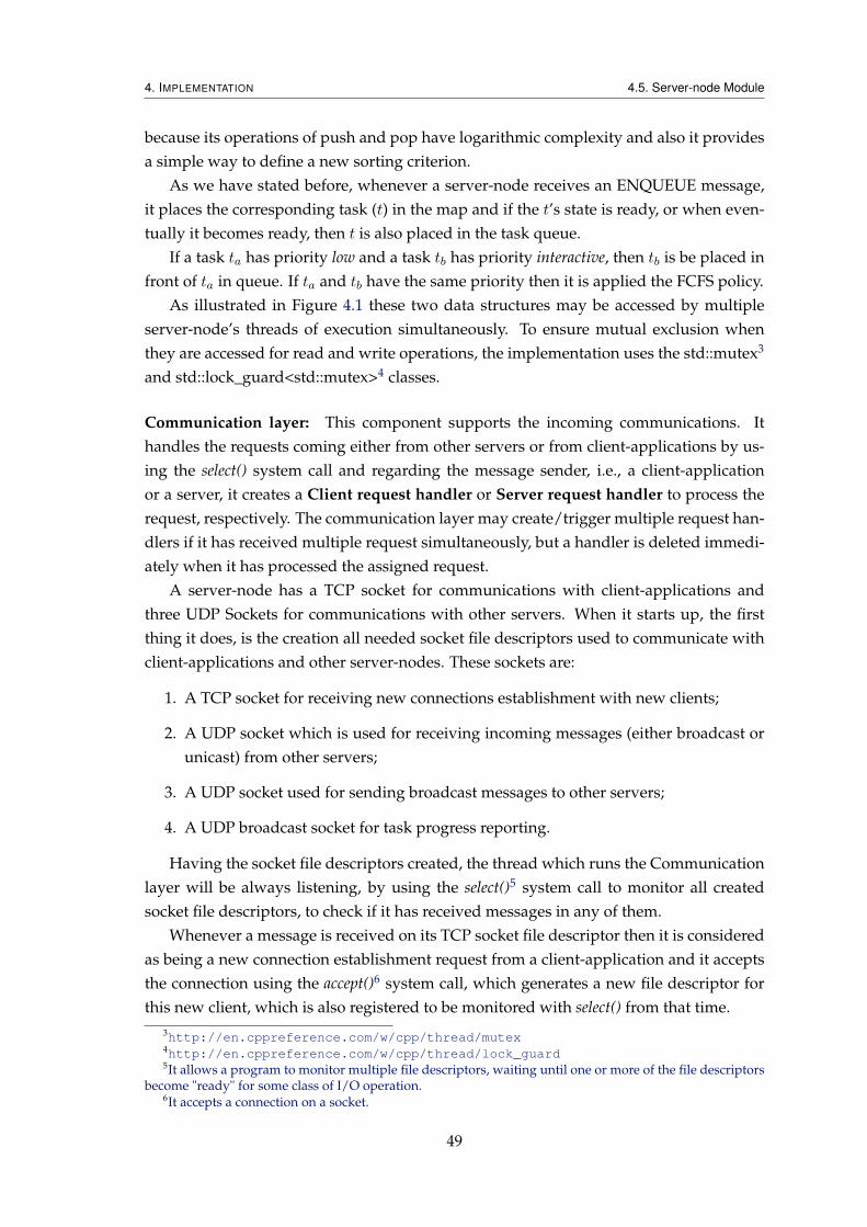
4. IMPLEMENTATION 4.5. Server-node Module
because its operations of push and pop have logarithmic complexity and also it providesa simple way to define a new sorting criterion.
As we have stated before, whenever a server-node receives an ENQUEUE message,it places the corresponding task (t) in the map and if the t’s state is ready, or when even-tually it becomes ready, then t is also placed in the task queue.
If a task ta has priority low and a task tb has priority interactive, then tb is be placed infront of ta in queue. If ta and tb have the same priority then it is applied the FCFS policy.
As illustrated in Figure 4.1 these two data structures may be accessed by multipleserver-node’s threads of execution simultaneously. To ensure mutual exclusion whenthey are accessed for read and write operations, the implementation uses the std::mutex3
and std::lock_guard<std::mutex>4 classes.
Communication layer: This component supports the incoming communications. Ithandles the requests coming either from other servers or from client-applications by us-ing the select() system call and regarding the message sender, i.e., a client-applicationor a server, it creates a Client request handler or Server request handler to process therequest, respectively. The communication layer may create/trigger multiple request han-dlers if it has received multiple request simultaneously, but a handler is deleted immedi-ately when it has processed the assigned request.
A server-node has a TCP socket for communications with client-applications andthree UDP Sockets for communications with other servers. When it starts up, the firstthing it does, is the creation all needed socket file descriptors used to communicate withclient-applications and other server-nodes. These sockets are:
1. A TCP socket for receiving new connections establishment with new clients;
2. A UDP socket which is used for receiving incoming messages (either broadcast orunicast) from other servers;
3. A UDP socket used for sending broadcast messages to other servers;
4. A UDP broadcast socket for task progress reporting.
Having the socket file descriptors created, the thread which runs the Communicationlayer will be always listening, by using the select()5 system call to monitor all createdsocket file descriptors, to check if it has received messages in any of them.
Whenever a message is received on its TCP socket file descriptor then it is consideredas being a new connection establishment request from a client-application and it acceptsthe connection using the accept()6 system call, which generates a new file descriptor forthis new client, which is also registered to be monitored with select() from that time.
3http://en.cppreference.com/w/cpp/thread/mutex4http://en.cppreference.com/w/cpp/thread/lock_guard5It allows a program to monitor multiple file descriptors, waiting until one or more of the file descriptors
become "ready" for some class of I/O operation.6It accepts a connection on a socket.
49

4. IMPLEMENTATION 4.5. Server-node Module
When it receives a message in one of registered file descriptors for client applicationthen it creates a thread to handle that client request, which can be the scheduling orcancelling of task, or task subscription request.
When it receives a message in one of its UDP file descriptors from another server,which can be a broadcast or unicast message, then it creates a thread to handle thatserver’s request. The kinds of messages which can arrive to its UDP file descriptors are,WHO_IS_MASTER, START_NEW_MASTER_ELECTION, ENQUEUE, TRY_DEQUEUE,STATE, GET_TASK, etc., that were previously described in Sections 3.6.1 and 3.6.2.
Task failure detector: This component is responsible for detecting the failures of tasksrunning remotely, i.e., the tasks running by the other servers. Every server-node has adedicated thread, which runs this component, for detecting the task execution failureperiodically (every 60 seconds) and when: there is at least one task running on a remotehost. This is to avoid the thread from being always wasting the host computing resourceswhen there is no task running on remote host to detect its failure. A task t runningremotely is considered as failed if the server-node has not received its progress for agiven time limit. In such case, this component reschedules t by adding it again to theTask queue.
If the Task executer is running a task t and it has to stop the t’ execution because itdetects that another node is also running t, then it may wake up the Task failure detectorto start checking if t does not fail.
Volunteer mode checker: This component is responsible for checking, periodically, whetherthe host is idle or not. Our implementation considers that a host becomes idle if its CPUload keeps being less than or equals 10% since last verification time. This checking isdone every 60 second intervals. It is run by a dedicated thread which only checks the CPUidleness if there is no task running locally. In other words, if a server-node is currentlyrunning a task then it cannot contribute with its computing resources to run another task.Taking this issue into account, it does not make sense to check if it is idle or not. To get thecurrent CPU load percentage we use the Windows Performance Data Helper functions7 for collecting host’s performance data. Although being our implementation portable,this feature has not yet been implemented for Unix environments. Currently, we are con-sidering that a server-node running on Unix can always try to dequeue a task even if thehost is not idle.
Task executer: This component is run by a thread and it is responsible for cooperat-ing with other servers in order to try dequeuing a ready task from Task queue. It runsthe distributed dequeuing algorithm (presented in Algorithm 3.2), which has a for loopwhere in each step it tries to get a task from the Task queue to execute. In each iterationof its for loop, it blocks on a condition variable until the following conditions are true: the
7http://msdn.microsoft.com/en-us/library/aa939698(v=winembedded.5).aspx
50

4. IMPLEMENTATION 4.5. Server-node Module
Listing 4.2: Example of the server configuration file.1 <?xml version="1.0" encoding="utf-8"?>2 <server>3 <reputation>10</reputation>4 <first_startup>true</first_startup>5 </server>
host CPU is idle, there is no other task running locally and the Task queue is not empty.The server-node’s threads which may signal this condition variable are: the Volunteermode checker component which decides whether the host CPU is idle or not, the Clientrequest handler which may generate a new task if a client-application has requested ascheduling and the Server request handler which may receive an ENQUEUE message orsome information that makes the state of a pending/dependent task to become Ready, forexample when a server-node receives the results of dependable task that has terminatedthe execution.
When a server-node receives a scheduling request from a client-application then itchecks the task’s priority. If it is interactive then the task should be executed locally if thereis no other running, even if the host is not idle. Otherwise, the system will eventuallyexecute it and should save the execution results on the database server.
Up to now, we consider a batch task as being one with priority low and interactive taskas being one with priority interactive, i.e., a task in which the user wants to get results assoon as possible.
Running task: It represents a task during the execution. The task execution is launchedby the Task executer as a child process and they communicate through the standard input(stdin) and standard output (stdout). The messages exchanged between them, follow thecommunication protocol defined in Section 3.5.
Progress reporter: This component is responsible for reporting the progress of a run-ning task, periodically (every 15 seconds), to other servers by broadcasting the PROGRESSmessage and to the client-applications which have subscribed interest in getting this taskprogress, by iterating the list of socket file descriptors of task’s subscribers, and for eachone it sends the PROGRESS message directly.
The component is run by a dedicated thread which waits on a condition variable untilTask executer starts running a task.
Master election: This component represents the master election algorithm which is runby a thread locally in the node whenever the system needs to elect a new master. Thethread is triggered/created to run the algorithm and deleted when the election termi-nates. As described in Section 3.6.1, the election algorithm has as input the node’s repu-tation loaded from a configuration file (provided in Listing 4.2). By default, every sever-node starts with the same reputation, which is later decremented whenever a node stops
51

4. IMPLEMENTATION 4.6. Execution Logging
and restarts. The first time a node joins the system, its reputation is not decremented, butthe content the element first_startup is set as false. In this way, the next time itrestarts for some reason (e.g., it has crashed), then it will check the content of that elementand decrement the value of reputation.
4.6 Execution Logging
Every server-node stores its execution log in a persistent logging file, for allowing thelater retrieving of historical data of its behaviour and statistical data. The same executionlog is also displayed on its console, in order to monitor its execution in real-time andanalyse the reasons of unwanted behaviours.
To achieve this, our implementation uses the Boost Log library8, which is simple to in-tegrate with an existing application and also extensible. Each line that is saved in the logfile has a severity associated, for better understanding about what happened. The formatof the log messages are shown below, where [YYYY-MM-DD HH:MI:SS] corresponds tothe date and time of day that the message was generated.
• [YYYY-MM-DD HH:MI:SS]: <normal> A normal severity message;
• [YYYY-MM-DD HH:MI:SS]: <error> An error severity message;
• [YYYY-MM-DD HH:MI:SS]: <debug> A debug severity message;
• [YYYY-MM-DD HH:MI:SS]: <info> An information severity message;
• [YYYY-MM-DD HH:MI:SS]: <warning> A warning severity message.
Listing 4.3 shows an excerpt of a server log file, where can be seen some informationthat is output by a server, namely its CPU load, TRY_DEQUEUE message, reception oftask’s states from other servers, etc.
In the next chapter we evaluate the system taking into consideration the results ob-tained from a simulation framework that we have developed.
8http://www.boost.org/doc/libs/1_55_0/libs/log/doc/html/index.html
52
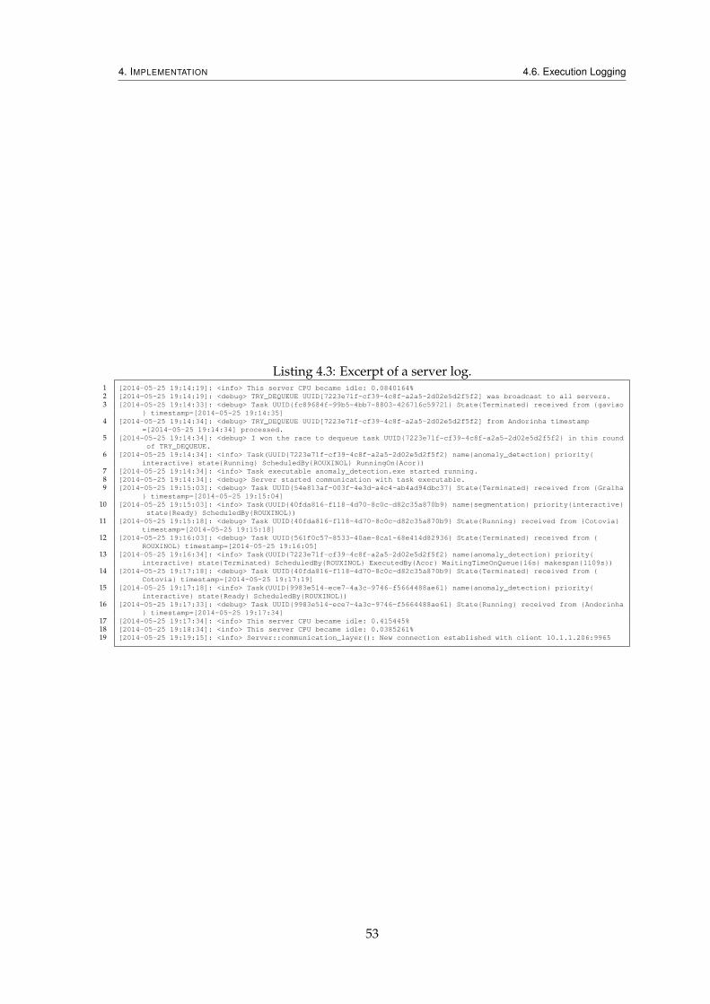
4. IMPLEMENTATION 4.6. Execution Logging
Listing 4.3: Excerpt of a server log.1 [2014-05-25 19:14:19]: <info> This server CPU became idle: 0.0840164%2 [2014-05-25 19:14:19]: <debug> TRY_DEQUEUE UUID[7223e71f-cf39-4c8f-a2a5-2d02e5d2f5f2] was broadcast to all servers.3 [2014-05-25 19:14:33]: <debug> Task UUID{fc89684f-99b5-4bb7-8803-426716c59721} State{Terminated} received from {gaviao
} timestamp=[2014-05-25 19:14:35]4 [2014-05-25 19:14:34]: <debug> TRY_DEQUEUE UUID[7223e71f-cf39-4c8f-a2a5-2d02e5d2f5f2] from Andorinha timestamp
=[2014-05-25 19:14:34] processed.5 [2014-05-25 19:14:34]: <debug> I won the race to dequeue task UUID{7223e71f-cf39-4c8f-a2a5-2d02e5d2f5f2} in this round
of TRY_DEQUEUE.6 [2014-05-25 19:14:34]: <info> Task(UUID{7223e71f-cf39-4c8f-a2a5-2d02e5d2f5f2} name{anomaly_detection} priority{
interactive} state{Running} ScheduledBy{ROUXINOL} RunningOn{Acor})7 [2014-05-25 19:14:34]: <info> Task executable anomaly_detection.exe started running.8 [2014-05-25 19:14:34]: <debug> Server started communication with task executable.9 [2014-05-25 19:15:03]: <debug> Task UUID{54e813af-003f-4e3d-a4c4-ab4ad94dbc37} State{Terminated} received from {Gralha
} timestamp=[2014-05-25 19:15:04]10 [2014-05-25 19:15:03]: <info> Task(UUID{40fda816-f118-4d70-8c0c-d82c35a870b9} name{segmentation} priority{interactive}
state{Ready} ScheduledBy{ROUXINOL})11 [2014-05-25 19:15:18]: <debug> Task UUID{40fda816-f118-4d70-8c0c-d82c35a870b9} State{Running} received from {Cotovia}
timestamp=[2014-05-25 19:15:18]12 [2014-05-25 19:16:03]: <debug> Task UUID{561f0c57-8533-40ae-8ca1-68e414d82936} State{Terminated} received from {
ROUXINOL} timestamp=[2014-05-25 19:16:05]13 [2014-05-25 19:16:34]: <info> Task(UUID{7223e71f-cf39-4c8f-a2a5-2d02e5d2f5f2} name{anomaly_detection} priority{
interactive} state{Terminated} ScheduledBy{ROUXINOL} ExecutedBy{Acor} WaitingTimeOnQueue{16s} makespan{1109s})14 [2014-05-25 19:17:18]: <debug> Task UUID{40fda816-f118-4d70-8c0c-d82c35a870b9} State{Terminated} received from {
Cotovia} timestamp=[2014-05-25 19:17:19]15 [2014-05-25 19:17:18]: <info> Task(UUID{9983e514-ece7-4a3c-9746-f5664488ae61} name{anomaly_detection} priority{
interactive} state{Ready} ScheduledBy{ROUXINOL})16 [2014-05-25 19:17:33]: <debug> Task UUID{9983e514-ece7-4a3c-9746-f5664488ae61} State{Running} received from {Andorinha
} timestamp=[2014-05-25 19:17:34]17 [2014-05-25 19:17:34]: <info> This server CPU became idle: 0.415445%18 [2014-05-25 19:18:34]: <info> This server CPU became idle: 0.0385261%19 [2014-05-25 19:19:15]: <info> Server::communication_layer(): New connection established with client 10.1.1.206:9965
53

4. IMPLEMENTATION 4.6. Execution Logging
54

5Evaluation
This chapter presents and evaluates the results obtained from several executions of thedeveloped prototype, considering different test configurations. Section 5.1 provides abrief presentation of functional requirements evaluation. In Section 5.2 we describe animplementation of a simulation framework that we have developed for automatic test-ing purposes and we evaluate the prototype taking into consideration the experimentalresults obtained from several tests. Finally, the Section 5.3 evaluates the satisfaction ofnon-functional requirements by our prototype.
5.1 Functional Evaluation
In Table 3.1 of Section 3.1, we have summarized the functional requirements that thesystem should meet. The majority of these requirements were fully satisfied, some ofthem were partially satisfied and just one was not, as shown in Table 5.1, where onecheck mark (X) means partially satisfied, two check marks (XX) means fully and nocheck mark means not satisfied.
5.2 Experimental Evaluation
In this section we present and evaluate the developed prototype, using a simulationframework for automatic tests. We also present an evaluation of non-functional require-ments that the system should meet, which were previously specified in Section 3.1.
55

5. EVALUATION 5.2. Experimental Evaluation
ID Satisfaction Comments
FR1 X It was partially satisfied because the system is able to exploit idle computing time ofworkstations but currently it only executes simulated tasks of PLMI2 application,instead of real tasks, since these were not available.
FR2 XX It was provided a way to represent dependencies among tasks, as defined in 4.4.FR3 XX The system is able to distinguish an interactive from batch task, as specified in
Section 4.5.FR4 XX Client applications can request the scheduling, cancellation and subscription of a
task, by following the protocols defined in Section 3.4.FR5 This requirement was not satisfied because it was not possible to implement any
User Interface for client applications due to time constraints. It was desirable tohave but not crucial.
Table 5.1: Functional requirements satisfaction.
Hostname CPU (model + speed) RAM Storage
acor Intel(R) Core(TM) i5-2400S 2.56 GHz 4 GB 931 GBandorinha Intel(R) Core(TM) i5-3570T 2.30 GHz 4 GB 456 GBcorredor Intel(R) Core(TM) i5-3570T 2.30 GHz 4 GB 465 GBcotovia Intel(R) Core(TM) i5-2400 3.10 GHz 4 GB 931 GBgaviao Intel(R) Core(TM) i5-3570T 2.30 GHz 4 GB 456 GBgralha Intel(R) Core(TM) i7-2600K 3.40 GHz 8 GB 175 GBgrifo Intel(R) Core(TM) i5-3570T 2.3 GHz 4 GB 500 GBpato AMD Athlon(tm) II X3 440 Processor 3.00 GHz 4 GB 156 GBrouxinol Intel(R) Core(TM) i5-3570T 2.30 GHz 4 GB 465 GB
Table 5.2: List of workstations used to test the system.
5.2.1 Computing Resources
To measure the system scalability and the ability for supporting the fault-tolerance, weused nine workstations within the Albatroz’s local network. Their characteristics arepresented in Table 5.2 and all of them have the same operating system type, which isWindows 64-bit.
5.2.2 Simulation Framework
To test the system, we developed four simulated tasks’ executables, as described below.The code for all tasks’ executables is portable for both Unix-like and Windows operatingsystem. Each one of them respects the communication protocol between a server-nodeand a running task that we have previously specified in Section 3.5.
import This task’s executable simulates the inspection data importing to the databaseserver.
georeferencing This task’s executable simulates the geo-referencing of the imported dataon database.
segmentation This executable simulates the classification of points of interest as ground,vegetation, road, building, etc.
56

5. EVALUATION 5.2. Experimental Evaluation
anomaly_detection This task’s executable simulates the classification of points of inter-est as an anomaly or not-an-anomaly, considering their distances to the power line.
The tasks’ executables were implemented in such way that they can be executed asthe following (command line-like):
$ ./task_exec_name [−p path_to_raw_files] [−i input1] ... [−i inputn] [−x parameters.xml] >
ouput1 ... outputn
task_exec_name The name of a task’s executable.
[-p path_to_raw_files] This option means that a location in the file system (or a location withinthe LAN) containing the raw data files was passed. This option is only needed for theimport task.
[-i input_nth] This option indicates that an integer number identifying an input dataset on databasewas passed. The number of input datasets to be passed to a task should be according to itsneed.
[-x parameters.xml] Indicates that an XML file with more task’s parameters was passed.
ouput1 ... outputn are the identifiers of output datasets generated by the task’s executable. Theseidentifiers are supposed to be obtained when the task’s executable generates datasets ondatabase, but currently they are randomly generated by the simulated tasks.
We developed a dedicated tester application for automatic simulation of client-applications, whereeach client-application requests a server-node to schedule those four tasks described above. Thepriority of each task is chosen randomly according to a uniform distribution in interval [1, 2], inwhich 1 means low and 2 means interactive priority, respectively.
Basically, the tester application creates between one and ten clients-applications by pickingup a random number generated with a uniform distribution in interval [1, 10]. Also, this tester iseasily expansible to support more server-nodes and client-applications.
We used nine workstations to work as the server-nodes (i.e., the server-node application wasinstalled in each one) and a client-application chooses to which server-node to request the execu-tion of its tasks randomly according to a uniform distribution in interval [1, 9].
5.2.3 Test Configurations
The dedicated tester application that was implemented, may launch a specified number client-applications, where each client-application requests the scheduling of one workflow containingfour tasks (illustrated in Figure 5.1) and the server-node to which a client-application requests thescheduling of its workflow is selected randomly, according to the number of servers used in eachtest configuration.
To show that the system is scalable with the increasing number of server-nodes we had to im-pose some restrictions on the test configuration, differently from that described in Section 5.2.2;i.e., in this case, some simulation parameters should not be chosen randomly, namely, the totaltask execution time and the number of client-applications. Indeed, we impose each task to takeexactly 2 minutes to complete its execution, and for all tests, were scheduled 5, 10 and 15 work-flows, which correspond to 20, 40 and 60 tasks, respectively. Regarding task’s priority, we had touse the same seed for the uniform distribution, so that for every system execution tasks will have
57

5. EVALUATION 5.2. Experimental Evaluation
segmentation
import
anomaly_detection
georeferencing
B C
D E
A
F
Figure 5.1: Workflow used for testing purposes.
Number of server-nodes 5 workflows 10 workflows 15 workflows
1 52,03 100,76 149,752 18,76 44,19 54,373 14,79 26,34 45,064 12,76 20,97 35,315 11,63 19,30 28,126 10,00 16,57 24,187 9,59 15,10 20,768 9,55 13,50 18,689 9,23 13,16 18,08
Table 5.3: Average makespan in minutes by a workflow for each number of server-nodesin the system.
the same priority as in the first execution. The only simulation parameter which changes fromone test configuration to another is the number of server-nodes.
Although being the prototype developed in such a way that it only exploits the idle CPUcycles from workstations to execute tasks, we have to state that all tests were conducted withworkstations in fully dedicated mode to execute tasks, i.e., the server-node was the only userapplication running on each workstation.
5.2.4 Experimental Results
In this section we present the results which show that our system is efficient/scalable and resilientto server-nodes’ failures.
In Table 5.3 we present the results we have got with nine system executions, each one with adifferent number of server-nodes in the system and workflows. These results show that the aver-age makespan of a workflow – the time since the submission to the system until its termination –decreases with the increasing number of the server-nodes. For instance, with 9 server-nodes and10 workflows, in average a workflow took just 13,16 minutes to complete the execution, whilstwith 1 server-node it took 1 hour and 40,76 minutes.
In Figure 5.2, we show the relationship between the number of server-nodes and the averagecompletion time of a workflow, which uses the data previously presented in Table 5.3. This figure
58
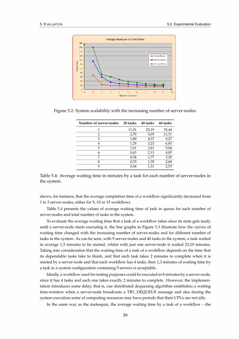
5. EVALUATION 5.2. Experimental Evaluation
Figure 5.2: System scalability with the increasing number of server-nodes.
Number of server-nodes 20 tasks 40 tasks 60 tasks
1 11,01 23,19 35,442 2,79 9,05 11,713 1,80 4,57 9,274 1,29 3,23 6,835 1,01 2,81 5,046 0,63 2,13 4,057 0,54 1,77 3,208 0,53 1,39 2,689 0,44 1,31 2,53
Table 5.4: Average waiting time in minutes by a task for each number of server-nodes inthe system.
shows, for instance, that the average completion time of a workflow significantly decreased from1 to 3 server-nodes, either for 5, 10 or 15 workflows.
Table 5.4 presents the values of average waiting time of task in queue for each number ofserver-nodes and total number of tasks in the system.
To evaluate the average waiting time that a task of a workflow takes since its state gets readyuntil a server-node starts executing it, the line graphs in Figure 5.3 illustrate how the curves ofwaiting time changed with the increasing number of server-nodes and for different number oftasks in the system. As can be seen, with 9 server-nodes and 40 tasks in the system, a task waitedin average 1,3 minutes to be started, whilst with just one server-node it waited 23,19 minutes.Taking into consideration that the waiting time of a task of a workflow depends on the time thatits dependable tasks take to finish, and that each task takes 2 minutes to complete when it isstarted by a server-node and that each workflow has 4 tasks, then 1,3 minutes of waiting time bya task in a system configuration containing 9 servers is acceptable.
Ideally, a workflow used for testing purposes could be executed in 8 minutes by a server-node,since it has 4 tasks and each one takes exactly 2 minutes to complete. However, the implemen-tation introduces some delay, that is, our distributed dequeuing algorithm establishes a waitingtime-window when a server-node broadcasts a TRY_DEQUEUE message and also during thesystem execution some of computing resources may have periods that their CPUs are not idle.
In the same way as the makespan, the average waiting time by a task of a workflow – the
59

5. EVALUATION 5.2. Experimental Evaluation
Figure 5.3: The average waiting time by a task in ready-to-run queue, according to thenumber of server-nodes in the system.
Number of server-nodes that failed Avg. waiting time of a task Avg. makespan of a workflow
8 out of 9 19,77 89,145 out of 9 3,35 22,812 out of 9 1,83 15,880 out of 9 1,31 13,16
Table 5.5: Average waiting time by a task and average makespan of a workflow, in min-utes, for each number of failed servers.
time since a task becomes ready until its execution is started by a server-node – also decreases asillustrated by three curves in Figure 5.3.
Note that the line graphs presented in Figure 5.2 and 5.3 have similar slopes. This happensbecause the makespan of a workflow is related with the waiting time of its tasks, that is, thegreater the waiting time higher is the makespan.
Fault Tolerance of Server-nodes
We have tested the fault-tolerance supporting of server-nodes when they were running tasks sev-eral times. For all tests the system was always able to detect their failures and reschedule the failedtasks. Moreover, to show that our system is resilient to the server-nodes failures, we have built4 test configurations, in which client-applications requested the scheduling of 10 workflows (40tasks) for a system with 9 server-nodes. Then, we intentionally caused 8, 5, 2 and 0 server-nodesto fail (i.e., cause them to leave the system) while they were running their first tasks, having thesystem started with 9 nodes. The remaining servers were able to detect the others’ failures andrescheduled the failed tasks. Therefore, the remaining server-nodes executed all 40 tasks thatwere scheduled, with success. The results of average waiting time by a task and makespan of aworkflow obtained from these system executions are shown in Table 5.5.
Fault Tolerance of Master Server
As we have presented previously, our system masks the master failure by electing a new oneaccording the election algorithm defined in Algorithm 3.1. We have tested the master failureseveral times, where the joining server-node was always able to detect this issue and trigger new
60

5. EVALUATION 5.3. Non-Functional Requirements Evaluation
ID Satisfaction Comments
NFR1 XX The system supports fault-tolerance of task execution, employing the reschedulemechanism and the failure of a server does not imply incorrect behaviour of theremaining, regarding the specifications provided in Sections 3.6.1.1 and 3.6.2.1.
NFR2 X The heterogeneity was partially met because the system was developed in sucha way that it works either for Unix-like and Windows operating systems, butfor Unix it is missing to implement the Volunteer mode checker component pre-sented in Section 4.5, and also it is missing some tests to ensure that communica-tion Unix ↔ Windows works.
NFR3 X Experimental results provided in Section 5.2.4, have shown that the developedprototype presents an acceptable total task execution time, but unfortunately wecannot compare these results with those of existing system because our resultswere obtained with simulated tasks. The real tasks of PLMI2 were not available.
NFR4 XX The performed tests have shown that a server-node has a low consumption ofworkstation resources, mainly the CPU usage.
Table 5.6: Non-functional requirements satisfaction.
election.
5.3 Non-Functional Requirements Evaluation
Table 5.6 presents whether a given non-functional requirement that was previously specified inTable 3.2 of Section 3.1, was met or not. The check marks have the same meaning as described inSection 5.1.
Summary
The results presented in this chapter show that the implemented system works as expected, interms of fault-tolerance supporting and scalability.
We have also shown how quickly the implemented prototype dispatches workflows by in-creasing the number of server-nodes and that it is resilient to the failures of server-nodes, even ifsome of them fail, since the system still having at least one server-node running.
61

5. EVALUATION 5.3. Non-Functional Requirements Evaluation
62

6Conclusions and Future Works
This thesis has studied a problem that emerged as a real need of Albatroz Engineering, with thepurpose of building a distributed task scheduling system able to schedule the execution of auto-matic tasks of a workflow of the company’s PLMI2 application, to be executed by the availableworkstations within the Local Area Network (LAN) and tailored to the company’s needs.
We have designed and implemented a new task scheduling system in the context of Vol-unteer Computing systems, which follows a distributed scheduling architecture, supports fault-tolerance of tasks execution by employing the rescheduling mechanism and takes into account thepriority of a task. The task scheduling policy follows the priority-based First Come First Served(FCFS).
The implementation of the prototype has addressed some of challenging issues raised by dis-tributed systems and Volunteer Computing, namely the dealing with hosts volatility and failures.
Furthermore, we have also defined three communication protocols between the system com-ponents:
• The protocol between a server-node and a task’s executable, which can be used to easilyadd new tasks to the system;
• The protocol between a client-application and a server-node, to allow the supporting ofnew client-applications;
• The protocol among the distributed server-nodes within the LAN, in order to achieve thedistributed task scheduling.
Our implementation relies mainly on two distributed algorithms, which respect a pre-establishedinteraction protocol among server-nodes, in order to be achieved the agreement in distributedscheduling of tasks.
The evaluation results have shown that the system prototype is scalable with the increasingnumber of server-nodes and that it is resilient to the failures of server-nodes. Also, the results haveshown that the system had in average an acceptable completion time of workflows dispatching
63

6. CONCLUSIONS AND FUTURE WORKS
(i.e., according to the expected), and that the average waiting time for the execution of a task tobe started by a server-node significantly decreases by adding more server-nodes to the system.
In order to extend the developed prototype, as a future work we recognize the need to:
• Improve our proposed distributed dequeuing algorithm to take into account the host CPUtype, where a server-node is running, in order to assign a task to the host with better prop-erties;
• Improve the system by adding a new scheduling policy to schedule tasks based on histor-ical behaviour of computing resources, since this mechanism can significantly lower theglobal tasks execution time [9];
• Improve the server-node to consider a host as being idle, not only when the CPU load islow, as it is currently implemented, but also the mouse and keyboard activities, i.e., whenthe user moves away from the workstation for a given time;
• Design and implement Graphical User Interfaces for client-application’s side, to inform theusers about the current system state and to allow them to request the scheduling of tasksexecution, cancelling the execution, etc.;
• Seamlessly integrate the developed prototype with PLMI2 platform.
64

Bibliography
[1] J. Gomes-Mota. About Albatroz Engineering - history, people, company data. URL: http://albatroz-eng.com/about_albatroz.php.
[2] J. Gomes-Mota. The history of Albatroz Engineering. URL: http://albatroz-eng.com/corporate/history.html.
[3] J. Gomes-Mota. Albatroz Engineering - Power Line Maintenance Inspection [PLMI].URL: http://albatroz-eng.com/solutions/power_line_maintenance_inspection.html.
[4] L. F. G. Sarmenta. “Volunteer Computing”. PhD thesis. Massachusetts Institute ofTechnology, 2001, p. 216. URL: http://dspace.mit.edu/handle/1721.1/16773.
[5] MersenneResearch. GIMPS. URL: http://www.mersenne.org/.
[6] Distributed.net. distributed.net. URL: http://www.distributed.net/.
[7] SETI@home. SETI@home. URL: http://setiathome.berkeley.edu/.
[8] D. P. Anderson, J. Cobb, E. Korpela, and M. Lebofsky. “SETI@home: An Experimentin Public-Resource Computing”. In: Communications of the ACM 45.11 (Nov. 2002),pp. 56–61. DOI: 10.1145/581571.581573.
[9] T. Estrada, O. Fuentes, and M. Taufer. “A Distributed Evolutionary Method to De-sign Scheduling Policies for Volunteer Computing”. In: Proceedings of the 2008 con-ference on Computing frontiers - CF ’08. New York, New York, USA: ACM Press,2008, pp. 40–49. ISBN: 9781605580777. DOI: 10.1145/1366230.1366282. URL:http://portal.acm.org/citation.cfm?doid=1366230.1366282.
[10] T. L. Casavant and J. O. N. G. G. Kuhl. “A Taxonomy of Scheduling in General-Purpose Distributed Computing Systems”. In: IEEE Transactions on Software Engi-neering 14.2 (1988), pp. 141–154. DOI: 10.1109/32.4634. URL: http://dl.acm.org/citation.cfm?id=630963.
65

BIBLIOGRAPHY
[11] L. F. Sarmenta. “Bayanihan: Web-Based Volunteer Computing Using Java”. In: Sec-ond International Conference on World-Wide Computing and its Applications. 1998, pp. 444–461. URL: http://citeseerx.ist.psu.edu/viewdoc/summary?doi=10.1.1.37.6643.
[12] S. Choi, H. Kim, E. Byun, and H. ChongSun. A Taxonomy of Desktop Grid SystemsFocusing on Scheduling. Tech. rep. Dept. of Computer Science & Engineering, KoreaUniversity, 2006, p. 17. URL: http://citeseerx.ist.psu.edu/viewdoc/summary?doi=10.1.1.75.5256.
[13] D. P. Anderson. “BOINC: A system for public-resource computing and storage”.In: 5th IEEE/ACM International Workshop on Grid Computing. 2004, pp. 4–10. URL:http://citeseerx.ist.psu.edu/viewdoc/summary?doi=10.1.1.123.
6649.
[14] C. Christophe and G. Fedak. Desktop Grid Computing. CRC Press, 2012, p. 388.ISBN: 9781439862155. URL: http://www.crcpress.com/product/isbn/9781439862148.
[15] HTCondor. HTCondor - Home. URL: http://research.cs.wisc.edu/htcondor/.
[16] Z. C. F. Scientific Computing, Copyright Nicolae. “A Desktop Grid Computing Ap-proach”. PhD thesis. URL: http://citeseerx.ist.psu.edu/viewdoc/summary?doi=10.1.1.139.1886.
[17] D. Zhou and V. Lo. “Wave Scheduler: Scheduling for Faster Turnaround Time inPeer-Based Desktop Grid Systems”. In: 11th Workshop on Job Scheduling Strategiesfor Parallel Processing. Springer, 2005, pp. 194–218. URL: http://citeseerx.ist.psu.edu/viewdoc/summary?doi=10.1.1.105.1922.
[18] Z. Zhao, F. Yang, and Y. Xu. “PPVC: A P2P volunteer computing system”. En-glish. In: 2009 2nd IEEE International Conference on Computer Science and Informa-tion Technology. Beijing: IEEE, Aug. 2009, pp. 51–55. ISBN: 978-1-4244-4519-6. DOI:10.1109/ICCSIT.2009.5234999. URL: http://www.computer.org/csdl/proceedings/iccsit/2009/4519/00/05234999-abs.html.
[19] A. A. Chien, B. Calder, S. Elbert, and K. Bhatia. “Entropia: Architecture and Perfor-mance of an Enterprise Desktop Grid System”. In: (2003). URL: http://citeseerx.ist.psu.edu/viewdoc/summary?doi=10.1.1.12.8273.
[20] P. Chauhan. “Decentralized Scheduling Algorithm for DAG Based Tasks on P2PGrid”. In: Journal of Engineering 2014 (2014), pp. 1–14. ISSN: 2314-4904. URL: http://www.readcube.com/articles/10.1155/2014/202843?locale=en.
[21] D. Moise, E. Moise, F. Pop, and V. Cristea. “Resource CoAllocation for SchedulingTasks with Dependencies, in Grid”. In: Proceedings of The Second International Work-shop on High Performance in Grid Middleware (HiPerGRID 2008). IEEE Romania, June2008, pp. 41–48. URL: http://arxiv.org/abs/1106.5309.
66
BIBLIOGRAPHY
[22] T. D. Braun, H. J. Siegel, A. A. Maciejewski, and Y. Hong. “Static resource allocationfor heterogeneous computing environments with tasks having dependencies , pri-orities , deadlines , and multiple versions”. In: J. Parallel Distrib. Comput. 68 (2008),pp. 1504–1516. DOI: 10.1016/j.jpdc.2008.06.006.
[23] G. Falzon and M. Li. “Enhancing genetic algorithms for dependent job schedulingin grid computing environments”. In: The Journal of Supercomputing 62.1 (Dec. 2011),pp. 290–314. ISSN: 0920-8542. URL: http://link.springer.com/10.1007/s11227-011-0721-2.
[24] D. Jakobovic and K. Marasovic. “Evolving priority scheduling heuristics with ge-netic programming”. In: Applied Soft Computing 12.9 (Sept. 2012), pp. 2781–2789.ISSN: 15684946. DOI: 10.1016/j.asoc.2012.03.065. URL: http://linkinghub.elsevier.com/retrieve/pii/S1568494612001780.
[25] A. Yu, Jia (The University of Melbourne and A. Buyya, Rajkumar (The University ofMelbourne. A taxonomy of scientific workflow systems for grid computing. New York,USA, 2005. DOI: 10.1145/1084805.1084814. URL: http://dl.acm.org/citation.cfm?doid=1084805.1084814.
[26] V. Pande. Folding@home. URL: http://folding.stanford.edu/.
[27] A. L. Perryman. FightAIDS@Home. URL: http://fightaidsathome.scripps.edu/.
[28] J. Barbosa and B. Moreira. “Dynamic Job Scheduling on Heterogeneous Clusters”.In: ISPDC ’09 Proceedings of the 2009 Eighth International Symposium on Parallel andDistributed Computing. 2009, pp. 3–10. DOI: 10.1109/ISPDC.2009.19.
[29] A. S. Tanenbaum and A. S. Woodhull. Operating Systems Design and Implementation.3rd. Prentice-Hall, Inc., Dec. 2005, p. 1099. ISBN: 0131429388. URL: http://dl.acm.org/citation.cfm?id=1076555.
[30] T. W. Doeppner. Operating Systems In Depth: Design and Programming. John Wiley& Sons, 2010, p. 444. ISBN: 978-0-471-68723-8. URL: http://eu.wiley.com/WileyCDA/WileyTitle/productCd-EHEP001803.html.
[31] A. Silberschatz, P. B. Galvin, and G. Gagne. Operating System Concepts with Java.7th. John Wiley & Sons, Inc., Nov. 2006, p. 966. ISBN: 0-471-76907-X. URL: http://codex.cs.yale.edu/avi/os-book/OS7/os7j/.
[32] Oracle. Monitoring and Managing the Scheduler. URL: http://docs.oracle.com/cd/B28359_01/server.111/b28310/schedadmin002.htm.
[33] Globus. GT 4.0 Pre WS GRAM Approach. URL: http : / / www . globus . org /toolkit/docs/4.0/execution/prewsgram/Pre_WS_GRAM_Approach.
html.
[34] Microsoft. Using Windows Compute Cluster Server 2003 Job Scheduler. URL: http://technet.microsoft.com/en-us/library/cc720125(v=ws.10).aspx.
67

BIBLIOGRAPHY
[35] V. Hamscher, U. Schwiegelshohn, A. Streit, and R. Yahyapour. “Evaluation of Job-Scheduling Strategies for Grid Computing”. In: Proceedings of the First IEEE/ACMInternational Workshop on Grid Computing. Springer-Verlag, 2000, pp. 191–202. URL:http://dl.acm.org/citation.cfm?id=645440.652831.
[36] M. Li and M. Baker. The Grid Core Technologies. John Wiley & Sons c©2005, 2005,pp. 243–254. ISBN: 9780470094174. URL: http://eu.wiley.com/WileyCDA/WileyTitle/productCd-0470094176.html.
[37] J. Cao, O. M. Kwong, X. Wang, and W. Cai. “A peer-to-peer approach to taskscheduling in computation grid”. In: International Journal of Grid and Utility Com-puting 1.1 (May 2005), pp. 13–21. ISSN: 1741-847X. DOI: 10.1504/IJGUC.2005.007056. URL: http://dl.acm.org/citation.cfm?id=1359318.1359320.
[38] M. R. A. GAREY and D. S. Johnson. Computers and Intractability: A Guide to the The-ory of NP-Completeness. 1979. ISBN: 0716710455. URL: http://dl.acm.org/citation.cfm?id=574848.
[39] D. G. Feitelson, L. Rudolph, and U. Schwiegelshohn. “Parallel Job Scheduling -A Status Report”. In: JSSPP’04 Proceedings of the 10th international conference on JobScheduling Strategies for Parallel Processing. Vol. 3277. Lecture Notes in Computer Sci-ence. Springer Berlin Heidelberg, 2005, p. 16. URL: http://www.springerlink.com/index/10.1007/b107134.
[40] E. Byun, S. Choi, M. Baik, J. Gil, C. Park, and C. Hwang. “MJSA: Markov job sched-uler based on availability in desktop grid computing environment”. In: Future Gen-eration Computer Systems 23.4 (May 2007), pp. 616–622. ISSN: 0167739X. URL: http://dx.doi.org/10.1016/j.future.2006.09.004.
[41] V. Kadappa, S. Ramachandram, and A. Govardhan. “Adaptive resource discov-ery models and Resource Selection in grids”. In: 2010 First International ConferenceOn Parallel, Distributed and Grid Computing (PDGC 2010). IEEE, Oct. 2010, pp. 95–100. ISBN: 978-1-4244-7675-6. DOI: 10.1109/PDGC.2010.5679878. URL: http://ieeexplore.ieee.org/lpdocs/epic03/wrapper.htm?arnumber=
5679878.
[42] D. Anderson, E. Korpela, and R. Walton. “High-Performance Task Distribution forVolunteer Computing”. In: First International Conference on e-Science and Grid Com-puting (e-Science’05). IEEE, Dec. 2005, pp. 196–203. URL: http://dl.acm.org/citation.cfm?id=1107836.1107874.
[43] Y. C. Lee, A. Y. Zomaya, and H. J. Siegel. “Robust task scheduling for volunteercomputing systems”. In: The Journal of Supercomputing 53.1 (Sept. 2009), pp. 163–181. ISSN: 0920-8542. URL: http://dl.acm.org/citation.cfm?id=1825310.1825317.
68

BIBLIOGRAPHY
[44] G. Falzon and M. Li. “Enhancing list scheduling heuristics for dependent job schedul-ing in grid computing environments”. In: The Journal of Supercomputing 59.1 (Mar.2010), pp. 104–130. ISSN: 0920-8542. DOI: 10.1007/s11227-010-0422-2. URL:http://link.springer.com/10.1007/s11227-010-0422-2.
[45] D. P. Anderson and J. M. Vii. Local Scheduling for Volunteer Computing. 2007. URL:http://citeseerx.ist.psu.edu/viewdoc/summary?doi=10.1.1.89.
4566.
[46] D. S. Milojicic, V. Kalogeraki, R. Lukose, K. Nagaraja, J. Pruyne, R. Bruno, S. Rollins,and Z. Xu. Peer-to-peer Computing. Tech. rep. URL: http://citeseerx.ist.psu.edu/viewdoc/summary?doi=10.1.1.9.8222.
[47] P. D. Beth Plale. “Key Concepts and Services of a Grid Information Service”. In:15th International Conference on Parallel and Distributed Computing Systems (PDCS).2002. URL: http://citeseerx.ist.psu.edu/viewdoc/summary?doi=10.1.1.19.209.
[48] J. Barbosa, C. Morais, R. Nobrega, and A. Monteiro. “Static scheduling of depen-dent parallel tasks on heterogeneous clusters”. In: Cluster Computing, 2005. IEEEInternational. Vol. 20005. Burlington, MA, 2005, pp. 1–8. DOI: 10.1109/CLUSTR.2005.347024. URL: http://ieeexplore.ieee.org/xpl/articleDetails.jsp?arnumber=4154152.
[49] G. Falzon and M. Li. “Evaluating Heuristics for Scheduling Dependent Jobs in GridComputing Environments”. In: International Journal of Grid and High PerformanceComputing 2.4 (Jan. 2010), pp. 65–80. ISSN: 1938-0259. URL: http://dl.acm.org/citation.cfm?id=2439421.2439427.
[50] J. Blythe, S. Jain, E. Deelman, Y. Gil, K. Vahi, A. Mandal, and K. Kennedy. “TaskScheduling Strategies for Workflow-based Applications in Grids”. In: CCGRID ’05Proceedings of the Fifth IEEE International Symposium on Cluster Computing and theGrid (CCGrid’05) - Volume 2. Washington, DC, USA: IEEE Computer Society, 2005,pp. 759–767. URL: http://dl.acm.org/citation.cfm?id=1169581.
[51] Y. C. Lee, R. Subrata, and A. Y. Zomaya. “On the Performance of a Dual-ObjectiveOptimization Model for Workflow Applications on Grid Platforms”. In: IEEE Trans-actions on Parallel and Distributed Systems 20.9 (2009), pp. 1273–1284. DOI: 10.1109/TPDS.2008.225.
[52] O. Sonmez, N. Yigitbasi, S. Abrishami, A. Iosup, and D. Epema. “Performance anal-ysis of dynamic workflow scheduling in multicluster grids”. In: HPDC ’10 Proceed-ings of the 19th ACM International Symposium on High Performance Distributed Com-puting. 2010, pp. 49–60. ISBN: 9781605589428. DOI: 10.1145/1851476.1851483.
[53] P. J. Leach, M. Mealling, and R. Salz. A Universally Unique IDentifier (UUID) URNNamespace. 2005. URL: http://tools.ietf.org/html/rfc4122.
69

BIBLIOGRAPHY
[54] C. Cachin, R. Guerraoui, and L. Rodrigues. Introduction to Reliable and Secure Dis-tributed Programming. Berlin, Heidelberg: Springer Berlin Heidelberg, 2011. ISBN:978-3-642-15259-7. DOI: 10.1007/978-3-642-15260-3. URL: http://link.springer.com/10.1007/978-3-642-15260-3.
[55] B. Stroustrup. C++11 FAQ. URL: http://www.stroustrup.com/C++11FAQ.html.
[56] L. Parziale, D. W. Liu, C. Matthews, N. Rosselot, C. Davis, J. Forrester, D. T. Britt,and I. Redbooks. TCP/IP Tutorial and Technical Overview. IBM Redbooks, 2006, p. 998.URL: http://www.redbooks.ibm.com/abstracts/gg243376.html.
[57] R. Sandberg, D. Goldberg, S. Kleiman, D. Walsh, and B. Lyon. “Design and Imple-mentation of the Sun Network Filesystem”. In: Summer ’85 USENIX. Sun Microsys-tems. Inc., 1985. URL: http://citeseerx.ist.psu.edu/viewdoc/summary?doi=10.1.1.14.473.
[58] SAS. The BSD UNIX Socket Library. 2001. URL: http://support.sas.com/documentation/onlinedoc/sasc/doc700/html/lr2/lr2bsd.htm.
[59] Microsoft. Windows Sockets 2 API. URL: http://msdn.microsoft.com/en-us/library/windows/desktop/ms740673(v=vs.85).aspx.
70

AAppendix
A.1 List of Acronyms
AT Automatic Task
CPU Central Processing Unit
DAG Directed Acyclic Graph
ECT Estimated Completion Time
FCFS First Come First Served
FIFO First In First Out
GIMPS Great Internet Mersenne PrimeSearch
GIS Grid Information Service
GPIS Grid Peer Information Service
GPS Global Positioning System
GUI Graphical User Interface
HEFT Heterogeneous Earliest Finish Time
IMU Inertial Measurement Unit
LAN Local Area Network
LiDAR Light Detection and Ranging
MT Manual Task
P2P Peer-to-Peer
PGS Peer-to-peer Grid Scheduling
PPVC A P2P Volunteer Computing System
PLMI Power Line Maintenance Inspection
PoI Point of Interest
SETI Search for ExtraterrestrialIntelligence
SJF Shortest Job First
SCV Sistema de Computação Voluntária
TA Tarefa Automática
TBA Task-Based Approach
TM Tarefa Manual
TCP Transmission Control Protocol
UDP User Datagram Protocol
UUID Universally Unique Identifier
VC Volunteer Computing
VCS Volunteer Computing System
WAN Wide Area Network
WBA Workflow-Based Approach
XML eXtensible Markup Language
71