a d d e n d u m - iowa
TRANSCRIPT
A d d e n d u m Iowa Department of Transportation Date of Letting: June 20, 2017
Office of Contracts Date of Addendum: June 15, 2017
B.O. Proposal ID Proposal Work Type County Project Number Addendum
001 07-0636-075 BRIDGE NEW ‐ PPCB Black Hawk NHSX-063-6(75)--3H-07 NHSX-063-6(87)--3H-07 NHSX-063-6(90)--3H-07 NHSX-063-6(92)--3H-07 NHSN-063-6(94)--2R-07 NHSX-063-6(96)--3H-07 NHSN-063-6(97)--2R-07
20JUN001A08
Change Proposal Line No. 2210: From: 2599-9999005 ACCESS, MANHOLE, SQUARE BASE, 48 IN. To: 2599-9999005 ACCESS, MANHOLE, CIRCULAR BASE, 48 IN. Change Proposal Line No. 2230: From: 2599-9999005 ACCESS, MANHOLE, SQUARE BASE, 96 IN To: 2599-9999005 ACCESS, MANHOLE, CIRCULAR BASE, 96 IN If the above changes are not made, they will be made as shown here.
Replace SP-150240b with the attached SP-150240c Replace SP-150243a with the attached SP-150243b Note: Product data sheets are attached at the end. PLAN: NHSX-063-6(96)--3H-07
Replace SHEETS NUMBER A.3, C.1 and O.1 with the attached SHEETS NUMBER A.3, C.1 and O.1:
SP-150240c (Replaces SP-150240b)
SPECIAL PROVISIONS FOR
GROUNDWATER SUPPRESSION SYSTEM
Black Hawk County NHSX-063-6(96)--3H-07
Effective Date March 21, 2017
THE STANDARD SPECIFICATIONS, SERIES 2015, ARE AMENDED BY THE FOLLOWING MODIFICATIONS AND ADDITIONS. THESE ARE SPECIAL PROVISIONS AND THEY SHALL PREVAIL OVER THOSE PUBLISHED IN THE STANDARD SPECIFICATIONS. 150240c.01 DESCRIPTION.
A. This specification covers the work for constructing the Groundwater Suppression System (GWSS). The work shall include construction of groundwater interceptor trenches, conveyance piping, access manholes, regulator manholes, and modifications to the existing Edward Street Lift Station Culvert. The casing installation of Canadian Railroad undercrossing is covered under Special Provisions for Auger Boring.
B. The final constructed GWSS shall be continuous, and shall be capable of transporting collected groundwater along the full length of the groundwater interceptor trench.
C. The Contractor shall construct the GWSS in accordance with this special provision and the details shown on the plans.
D. The Contractor shall install the temporary shoring and dewatering for the GWSS in accordance with Special Provisions for Temporary Shoring and Temporary Dewatering System, and the plans.
E. Design Criteria: The structural design of access and regulator manholes shall be using the following parameters.
1. Groundwater table: elevation 845 feet.
2. Equivalent fluid pressure above groundwater table: 60 pounds per cubic foot.
3. Equivalent fluid pressure below groundwater table: 95 pounds per cubic foot.
4. Uniform Lateral surcharge pressure: 2500 pounds per square foot (from nearby MSE wall).
5. Nominal bearing resistance: 7500 pounds per square foot.
SP-150240c, Page 2 of 12
F. Qualifications. 1. The Contractor shall have a minimum of 5 years of experience and a minimum five projects
of constructing sewer, water drainage, and/or water pipes. Each project shall be a minimum length of 1000 feet of pipe.
2. The Contractor’s superintendent shall have at least 5 years and 2000 feet of experience in constructing sewer, water drainage, and/or water pipes.
150240c.02 MATERIALS.
A. Materials Excavated from GWSS Construction Excavated material shall be classified as per Article 2552.02, A of the Standard Specifications.
B. Stabilization Material.
Stabilization material shall comply with stabilization (foundation) material as specified in Article 2552.02, F of the Standard Specifications.
C. Controlled Low Strength Material (CSLM).
CSLM shall comply with Article 2552.02, G, 3 of the Standard Specifications.
D. Sand Filter. Acceptable Sand Filter products include: 1. US Silica FilPro – grade No.2.
2. Standard Sand and Silica – grade 6/20.
3. Colorado Silica Sand – grade 8/16. 4. Fairmont Santrol - product 620. 5. Red Flint Sand and Gravel - Filter Sand Product 1.20-1.60.
E. Granular Backfill.
The Granular backfill material shall be as per Section 4133 of the Standard Specifications.
F. Manhole Bedding. Class I bedding material shall meet the requirements of Section 4118 of the Standard Specifications.
G. Pipe.
1. Use slotted pipes in groundwater interceptor trench:
a. The slotted pipes shall be 12 inch nominal diameter, schedule 80 PVC, and 0.05 inch slot opening with 0.25 inch spacing between slots, manufactured by Certain Teed PVC Well Casing, Charlotte Pipe and Foundry Company, Crestline Plastic Pipe Company, Johnson Well Screen, or Roscoe-Moss Company.
b. Pipe size shall comply with ASTM D1785. c. PVC plastic shall meet ASTM D 1784, Cell Classification 12454. d. Integral bell and spigot joints with elastomeric seals meeting ASTM D 3212 and ASTM F
477 shall be used.
2. Ductile Iron Pipe. a. Piping.
SP-150240c, Page 3 of 12
1) The conveyance pipes shall be ductile iron and have nominal diameter as specified in the plans.
2) Pressure class shall be 250 psi minimum working pressure, conforming to Table 5 and Table 7 for Type 5 trench in AWWA C151/A21.51.
b. Lining. Cement-mortar shall meet AWWA C104/A21.4 specifications.
c. Fittings. Push-on: AWWA C110/A21.10, AWWA C111/A21.11, and AWWA C153/A21.53 ductile iron, 250 pounds per square inch minimum working pressure. . American Cast Iron Pipe Co., Fastite Joint; U.S. Pipe and Foundry, Tyton Joint; or Clow Water System Co., Fastite Joint.
d. Joints. Push-on: 250 pounds per square inch minimum working pressure, AWWA C110/A21.10 and AWWA C111/A21.11. American Cast Iron Pipe Co., Fastite Joint; U.S. Pipe and Foundry, Tyton Joint; or Clow Water System Co., Fastite Joint.
e. Gaskets. 1) Push-on Mechanical Joints; Rubber shall conform to AWWA C111/A21.11. 2) Provide manufacturer’s standard gasket compatible with the pipe.
f. Joint Lubrication: shall meet the manufacturer’s standard.
H. Precast Concrete Manholes. Precast concrete manholes shall comply with storm sewer structure requirements in Section 2435 of the Standard Specifications, except:
1. The minimum 28 day precast concrete strength shall be 4000 pounds per square inch.
2. Reinforcing steel shall be uncoated ASTM A615, Grade 60.
3. Pipe connections to manholes shall be modular mechanical seal type connections
I. Cast-in-place Concrete Structural Component.
Cast-in-place concrete structural components including cast-in-place manhole base (if selected), end wall and pipe penetration closure collar at the existing culvert, shall comply with Section 2435 of the Standard Specifications, except the following:
1. The minimum 28 day concrete strength shall be 4000 pounds per square inch.
2. Limit the maximum water to cementitious material ratio to 0.40.
3. Reinforcing steel shall be uncoated ASTM A615, Grade 60.
4. Post installed adhesive Dowels: Adhesive for concrete doweling shall be approved by ICC
Evaluation Services Report for conforming to 2009 IBC requirements for doweling of steel reinforcing bars in cracked concrete. The adhesive shall be suitable for long-term loads as well as for seismic loads, meeting requirements of ASTM C881. The adhesive shall be two-components, insensitive to moisture and designed to be used in an adverse freeze/thaw environment.
5. Hydrophilic Waterstops: Hydrophilic waterstops shall be used at construction joints where new concrete is placed against existing concrete and as shown on the plans. The material shall be a nonbentonite hydrophilic rubber compound that will swell when in contact with water.
J. Assembly of Regulator Manholes.
1. Weir Wall.
SP-150240c, Page 4 of 12
Fabricate plates and associated framing using stainless steel meeting AISI Type 316 specifications.
2. Cast-In-Place Anchor Bolts. a. Headed type, unless otherwise shown on plans. b. AISI Type 316 stainless.
3. Post-Installed Concrete Anchors.
a. General. 1) Be AISI Type 316 stainless. 2) Have a current ICC-ES Report indicating acceptance per IBC 2012 for anchors at
structural applications in cracked concrete. 3) Be suitable for long-term loads.
b. Adhesive Anchors (Epoxy Anchors). 1) Adhesive anchors shall have a current ICC-ES Report that demonstrates compliance
with ICC-ES AC308 for cracked concrete. 2) Threaded Rods.
a) Be ASTM F593 stainless steel threaded rods with a diameter as shown on plans. b) Be of a length as required, to provide minimum depth of embedment. c) Be clean and free of grease, oil, or other deleterious material. d) For hollow-unit masonry, provide galvanized or stainless steel wire cloth screen
tube to fit threaded rod. 3) Adhesive.
a) Adhesive used shall be a two-component adhesive that is insensitive to moisture and designed to be used in adverse freeze/thaw environments.
b) Cure Temperature, Pot Life, and Workability: Adhesive shall be compatible for the intended use and anticipated environmental conditions.
c) Mixed Adhesive: The mixed adhesive shall have a nonsag light paste consistency with the ability to remain in a 1 inch diameter overhead drilled hole without runout.
d) Adhesive used shall meet the requirements of ASTM C881/C881M. 4) Packaging and Storage.
a) The adhesive used shall be a disposable, self-contained cartridge system capable of dispensing both components in proper mixing ratio and fitting into manually or pneumatically operated caulking gun.
b) Store adhesive cartridges and adhesive components on pallets or shelving in a covered storage area.
c) Container markings shall include the manufacturer’s name, product name, batch number, mix ratio by volume, product expiration date, ANSI hazard classification, and appropriate ANSI handling precautions.
d) Adhesive shall be disposed of when: (1) Its shelf life has expired. (2) It is stored in a manner not in accordance with manufacturer’s instructions.
5) Approved Adhesive Manufacturers and Products. a) Hilti, Inc., Tulsa, OK; HIT Doweling Anchor System, HIT RE 500 SD (ESR-2322). b) Simpson Strong-Tie Co., Inc., Pleasanton, CA; SET-XP Epoxy Adhesive Anchors
(ESR-2508). c) Powers Fasteners, Brewster NY, PE1000+ Adhesive anchoring system
(ESR-2583).
4. Adjustable Stem Guide for Regular Manhole Drain Valve. Stem Guides shall be constructed of ductile iron, grade 65-45-12. Stem guides fabricated by welding carbon steel shall not be permitted. Stem guides shall include a bronze bushing with an inside diameter 1/16 inch larger than the outside diameter of the extension stem and shall be retained with two stainless steel screws. The stem guide shall include an adjustable design for plumb alignment. The adjusting bolt and washer shall be type 316 stainless. Stem
SP-150240c, Page 5 of 12
guides shall be spaced so that the unsupported length between extension stems shall not exceed 6 feet.
5. Butterfly Drain Valve.
a. Butterfly Drain Valves shall be in full compliance with AWWA C504 and meet the following requirements: 1) Be suitable for throttling operations and infrequent operation after periods of
inactivity. 2) Have elastomer seats which are bonded or vulcanized to the body. The elastomer
seats shall have adhesive integrity of bond between seat and body assured by testing, with a minimum 75 pound pull in accordance with ASTM D429, Method B.
3) Be bubble-tight with rated pressure applied from either side. Valves shall be tested with pressure applied in both directions.
4) Have no travel stops for disc on interior of body. 5) Have self-adjusting V-type or O-ring shaft seals. 6) Have metal-to-metal thrust bearing surfaces isolated from flow stream. Provide
traveling nut or worm gear actuator with handwheel. Valve actuators shall meet the requirements of AWWA C504.
7) Have linings and coatings in accordance with AWWA, unless otherwise indicated on the plans or specified herein.
b. Type V500 Butterfly Valve Water Works Service 3 inches to 72 inches shall meet the following requirements 1) Be in full compliance with AWWA C504, Class 150B. 2) Be short body type, flanged ends. 3) Have cast-iron body, cast or ductile iron disc, Type 304 stainless steel shafts, Buna-N
rubber seat bonded or molded in body only, and stainless steel seating surface. 4) Have epoxy lining and coating in compliance with AWWA C550. 5) Approved manufacturers include the following:
a) Pratt; Model 2FII or Triton XR-70. b) DeZurik; AWWA Valve. c) Clow Valve; Stle 4500.
6. Valve Operator.
a. All valve operators shall meet the following requirements: 1) For AWWA valves, operator force shall not exceed requirements of the applicable
valve standard. The Contractor shall provide gear reduction operator when force exceeds requirements.
2) Operator shall be the self-locking type or be equipped with self-locking device. 3) Have a position indicator on quarter-turn valves. 4) Worm and gear operators one-piece design, worm-gears of gear bronze material.
Worm of hardened alloy steel with thread ground and polished. Traveling nut type operator’s threaded steel reach rod with internally threaded bronze or ductile iron nut.
b. Manhole valve operators shall meet the following requirements: 1) Manhole service operators on valves larger than 2 1/2 inches shall have a 2 inch
AWWA operating nut. Moving parts of valve and operator shall be enclosed in housing to prevent contact with the water.
2) Manhole service operators shall be grease packed and gasketed to withstand a submersion in water to 20 feet minimum.
3) Manhole valves shall have extension stems, bonnets, and valve boxes cast into manhole top slab.
7. Manhole Valve Accessories. a. Each manhole valve shall have two galvanized T-handled operating wrenches, 4 feet
long. b. Cast-Iron Valve Box shall be designed for traffic loads, sliding type, with minimum of 5
1/4 inch ID shaft.
SP-150240c, Page 6 of 12
1) Box shall be manufactured from cast iron with minimum depth of 9 inches. 2) Lid shall be manufactured from cast iron with minimum depth 3 inches, of a
nonlocking type, marked WATER or GAS as applicable. 3) Extensions shall be manufactured from cast iron. 4) Valves measuring 4 through 12 inches shall have a two piece box and lid, valves
larger than 12 inches shall have a three-piece box and lid with base sized for valve. 5) Valves with operating nuts shall have valve extension stems 3 feet or more below
finish grade. a) Approved manufacturers and products include the following:East Jordan Iron
Works; cast-iron valve boxes. b) Bingham & Taylor; cast-iron valve boxes. c) Castings Inc; cast-iron valve boxes.
8. Stainless Steel Pipe.
a. Piping. 1) Stainless steel piping shall have nominal diameter to match the butterfly valve as
specified in the plans. 2) Steel shall be schedule 40S: ASTM A778, “as-welded” grade, Type 316L, pickled and
passivated. b. Flanges.
Be of forged Stainless Steel, meeting ASTM A182/A182M, Grade F316L, ASME B16.5 Class 150 or Class 300, slip-on weld neck or raised face, and have weld slip-on flanges inside and outside.
c. Bolting. Forged Flanges shall be type 316 stainless steel, ASTM A320/A320M Grade B8M hex head bolts, ASTM A194/A194M Grade 8M hex head nuts and ASTM F436/F436M Type 3 alloy washers at nuts and bolt heads. Flanges shall achieve 40% to 60% of bolt minimum yield stress.
d. Gaskets. 1) Gaskets shall be used between the stainless steel flange and the butterfly valve. 2) Flanged, Water, and Hot Air Services shall be 1/8 inch thick, homogeneous black
rubber (EPDM), hardness 60 (Shore A), rated to 250°F, continuous and conforming to ASME B16.21 and ASTM D1330, Steam Grade.
K. Modular Mechanical Seal. 1. Modular mechanical seals shall be interconnected synthetic rubber links shaped and sized to
continuously fill the annular space between pipe and wall sleeve opening.
2. Fabrication. a. Interconnected rubber links shall be assembled with ASTM A276, Type 316 stainless
steel bolts and nuts. b. Pressure plates shall be reinforced nylon polymer.
3. Seals shall be sized according to manufacturer’s instructions for size of pipes shown to
provide a watertight seal between pipe and wall sleeve opening, and to withstand a hydrostatic head of 40 feet of water.
L. Additional Materials for Manholes.
1. Manhole Adjustment Rings shall comply with Article 4149.04, H of the Standard
Specifications.
2. Manhole Casting: Ring, frame and cover material shall comply with Article 4149.04, I, 1 and 2 of the Standard Specifications.
SP-150240c, Page 7 of 12
3. Steps shall comply with Article 4149.04, L of the Standard Specifications. 150240c.03 CONSTRUCTION.
A. Submittals. 1. The Contractor shall submit resumes showing required qualifications.
2. Work Plan.
a. The Contractor shall submit the work plan no later than 30 working days before beginning the Groundwater Suppression System construction. The Contractor shall submit the work plan to the Engineer for review and approval, and the GWSS construction shall not start until the Engineer approves the work plan.
b. The submitted work plan shall include the following: 1) Site Visit: The Contractor shall acknowledge that the job site has been visited to
verify the site conditions with regard to entrance, access, overhead lines, subsurface features, permitting, and collecting all information necessary to plan and execute the work.
2) List of Proposed Equipment: Include number and sizes of cranes; number and sizes of compaction equipment; cleaning equipment; and all relevant equipment necessary to complete the Groundwater Suppression System installation.
3) Details of Schedule for Construction Operations: Include a layout of the installation sequence.
3. Pipe laydown shop drawings.
4. Concrete Structures. a. Shop drawings.
1) Cast-in-place concrete component geometry, steel reinforcement sizes, lengths, bends and quantity.
2) Precast manhole structure showing general geometry, total depth, relative elevations and orientation of all connecting pipes and connection detail between precast segments. Shop drawing shall also include manhole cover, manhole invert and manhole steps.
b. Concrete mix design. 1) Concrete mix design shall contain proportions of materials and admixtures to be used
on Project, signed by mix design. Indicate location of the concrete mix to be used. 2) Submit documentation of average strength for each proposed mix design in
accordance with ACI301. Submit manufacturer’s certificate of compliance for Portland cement, supplemental cementitious material such as fly ash and slag cement, aggregates and admixtures.
c. Material Data. 1) Adhesive to be used for post-installed adhesive dowels. 2) Hydrophilic water stop at construction joint between new and existing concrete.
5. Product Data.
a. The manufacture’s product specification and catalog for the following items: 1) Hydrophilic waterstop. 2) Slotted PVC pipe. 3) Conveyance pipe.
b. Gradation report for the granular backfill, sand filter, and stabilization material. c. Name and location of the source of the granular backfill material.
B. General.
1. The Contractor shall carry out the work in accordance with the approved submittals.
SP-150240c, Page 8 of 12
Construction of the GWSS shall not commence until approval of the engineer has been obtain.
2. The Contractor shall review the construction sequence defined in the plans to properly
understand staging and sequencing requirements.
C. Excavation. 1. Excavation shall comply with Article 2552.03, A of the Standard Specifications.
2. Excavate to lines, grades, and dimensions shown and as necessary to accomplish work.
Excavate to within tolerance of plus or minus 0.1 foot, except where dimensions or grades are shown or specified as maximum or minimum. Allow for forms, working space, manhole bedding (if any), and any other construction items, wherever applicable. Trim to neat lines where concrete is to be deposited against earth.
3. Over excavation shall not be done without written authorization of Engineer.
D. Preparation of Excavation Bottom.
1. If unsuitable soils are encountered in trench bottom, the Contractor shall notify the Engineer
prior to over-excavation. Unsuitable material shall be as per definition specified in Article 2102.02, D, 2 of the Standard Specifications.
2. The Engineer will determine the need for over-excavation and trench foundation stabilization
prior to installation of pipes and structures.
3. If trench is over excavated, the Contractor shall place stabilization material over full width of trench in 6 inch lifts to the bottom of pipe zone. Each lift shall be compacted so as to provide a firm, unyielding support for the sand filter prior to placing succeeding lifts.
4. The Contractor shall ensure surface of excavation bottom is free of debris prior to placing any
pipe or structure.
E. Shoring. All work shall comply with Special Provisions for Temporary Shoring.
F. Dewatering.
All work shall comply with Special Provisions for Temporary Dewatering System.
G. Backfill for Groundwater Interceptor Trench and Conveyance Pipe.
1. Do not use power driven impact type compactors for compaction until at least 4 feet of material is placed over top of pipe.
2. Sand filter: Placement of sand filter material shall comply with Article 2552.03, E, 2 of the
Standard Specifications with the following stipulation: a. Pipe bedding placement requirements shall apply to sand filter placement of this project. b. Backfill material shall be as per plans and this special provision.
3. Granular backfill: Mechanically compact each lift to not less than 95% of Standard Proctor
Density prior to placing seceding lifts.
4. CLSM: Place CLSM for conveyance pipe segments specified in the plans. Secure pipe against displacement or flotation prior to placing CLSM.
SP-150240c, Page 9 of 12
H. Backfill around Manholes and Edward Street Lift Station Culvert. Backfill and compaction around manholes shall comply with Article 2435.03, A, 12 of the Standard Specifications, except:
1. Backfill around manhole below the existing grade shall be granular backfill material.
2. Backfill inside the abandoned potion of Edward Street Lift Station Culvert shall be CLSM,
within the limits as per the plans.
I. Buried Pipe Installation.
1. Joints. a. The Contractor shall provide concrete closure collar as shown in the plans. b. Concrete Encased or Embedded Pipe: Do not encase joints in concrete, unless
specifically shown. c. The Contractor shall provide flexible joints at all concrete structures:
1) Install a flexible joint 18 inches or less from face of structures; joint may be flush with face.
2) Install a second flexible joint within 18 inches of the first joint.
2. Placement of Buried Pipe. a. Keep trench dry until pipe laying and joining are completed. b. Exercise care when place the pipe into trench to prevent twisting or damage to pipe. c. Measure for grade at pipe invert, not at top of pipe. d. Excavate trench bottom and sides of ample dimensions to permit visual inspection and
testing of entire flange, valve, or connection. e. Prevent foreign material from entering pipe during placement. f. Close and block open end of last laid pipe section when placement operations are not in
progress and at close of day’s work. g. Lay pipe upgrade with bell ends pointing in direction of laying. h. Deflect pipe at joints for pipelines laid on a curve using unsymmetrical closure of spigot
into bell. If joint deflection of standard pipe lengths will not accommodate horizontal or vertical curves in alignment, provide: 1) Shorter pipe lengths. 2) Special mitered joints. 3) Standard or special fabricated bends.
i. After joint has been made, check pipe alignment and grade. j. Place sufficient pipe zone material to secure pipe from movement before next joint is
installed. k. Prevent uplift and floating of pipe prior to backfilling.
3. Placement of PVC Pipe.
a. Lay pipe snaking from one side of trench to other. b. Offset: As recommended by manufacturer for maximum temperature variation between
time of solvent welding and during operation. c. Shield ends to be joined from direct sunlight prior to and during the laying operation.
4. Tolerances.
a. Deflection from Horizontal Line, Except PVC: Maximum 2 inches. b. Deflection from Vertical Grade: Maximum 1/4 inch. c. Joint Deflection: Maximum of 75% of manufacturer’s recommendation. d. Horizontal position of pipe centerline on alignment around curves maximum variation of
1.75 feet from position shown. e. Pipe Cover: Minimum 3 feet, unless otherwise shown in the plans.
J. Valve Installation.
SP-150240c, Page 10 of 12
1. General. a. Install valves such that handles can operate from fully open to fully closed without
encountering obstructions. b. Install valves in location for easy access for routine operation and maintenance. c. Install valves in accordance with manufacturer’s recommendations.
2. Extension Stem for Operator: Where the depth of the valve operating nut is 3 feet or greater
below finish grade, the Contractor shall furnish an operating extension stem with 2 inch operating nut to bring operating nut to a point within 6 inches of finish grade.
K. Manhole Construction.
1. Subbase: For both case-in-place and precast manhole base, the Contractor shall install an 8
inch thick pad of Class I bedding material a minimum of 12 inches outside the footprint of the structure.
2. Installation of Manholes shall comply with Article 2435.03, A, 4 of the Standard
Specifications.
3. Install pipe flush with inside wall of structure.
4. Joint sealant shall comply with Article 2435.03, A, 6, b of the Standard Specifications.
5. Manhole invert is not required.
6. Manhole top sections shall comply with Article 2435.03, A, 8 of the Standard Specifications.
7. Manhole adjustment rings shall comply with Article 2435.03, A, 9 of the Standard Specifications.
8. Manhole casting shall comply with Article 2435.03, A, 10 of the Standard Specifications.
L. Cast-in-place Concrete Structures.
Cast-in-place structures shall be in compliance with Article 2435.03, B of the Standard Specifications.
M. Precast Concrete Structures.
Precast concrete structures shall be in compliance with Article 2435.03, C of the Standard Specifications.
N. Cleaning, Inspection, and Testing of Structures.
Cleaning, inspection, and testing shall be in compliance with Article 2435.03, F of the Standard Specifications, except that Sanitary Sewer Manhole Testing does not apply this project.
150240c.04 METHOD OF MEASUREMENT.
A. Excavation. Measurement for Excavation, in cubic yard, will be the quantity shown in the contract documents.
B. CLSM.
Measurement for CLSM, in cubic yard, will be the quantity shown in the contract documents.
C. Sand Filter. Measurement for Sand Filter, in cubic yard, will be the quantity shown in the contract documents.
D. Granular Backfill Material.
SP-150240c, Page 11 of 12
Measurement for Granular Backfill Material, in cubic yard, will be the quantity shown in the contract documents.
E. Groundwater Interceptor Trench. Measurement for Groundwater Interceptor Trench, in feet, will be the quantity shown in the contract documents.
F. Conveyance Pipe, 12 Inch.
Measurement for Conveyance Pipe, 12 Inch, in feet, will be the quantity shown in the contract documents.
G. Conveyance Pipe, 16 Inch. Measurement for Conveyance Pipe, 16 Inch, in feet, will be the quantity shown in the contract documents.
H. Access Manholes.
Each type and size of access manhole will be counted.
I. Regulator Manholes. Each type and size of regulator manhole will be counted.
J. Modification to the Existing Edward Street Lift Station Culvert. Each modification of the existing Edward Street Lift Station Culvert will be counted.
150240c.05 BASIS OF PAYMENT.
A. Excavation.
1. Payment for Excavation will be at the contract unit price per cubic yard.
2. Payment is full compensation for: All excavation, including both soil and rock, for the GWSS installation, and Preparation of Excavation Bottom, including over excavation, and furnishing and
placement of stabilization material. Removal and disposal of excavated material to a location outside of the project limits.
B. CLSM.
1. Payment for CLSM will be at the contract unit price per cubic yard.
2. Payment is full compensation for furnishing and placing CLSM outside of Edward Street Lift
Station Culvert area.
C. Sand Filter.
1. Payment for Sand Filter will be at the contract unit price per cubic yard.
2. Payment is full compensation for furnishing and placing sand filter.
D. Granular Backfill Material.
1. Payment for Granular Backfill Material will be at the contract unit price per cubic yard.
2. Payment is full compensation for furnishing and placing granular backfill material up to the existing ground.
SP-150240c, Page 12 of 12
E. Groundwater Interceptor Trench.
1. Payment for Groundwater Interceptor Trench will be at the contract unit price per linear foot.
2. Payment is full compensation for furnishing and installing slotted pipe.
F. Conveyance Pipe, 12 Inch. 1. Payment for Conveyance Pipe, 12 Inch, will be at the contract unit price per linear foot.
2. Payment is full compensation for furnishing and installing all conveyance pipes of the project,
including the conveyance pipes inside the auger bored casing.
G. Conveyance Pipe, 16 Inch.
1. Payment for Conveyance Pipe, 16 Inch, will be at the contract unit price per liner foot.
2. Payment is full compensation for furnishing and installing all conveyance pipes of the project, including the conveyance pipes inside the auger bored casing.
H. Access Manholes.
1. Payment will be at the contract unit price for each type and size of manhole.
2. Payment is compensation for furnishing and installing bedding, base, structural concrete, reinforcing steel, precast units, pipe connections, castings, and adjustment rings.
I. Regulator Manholes.
1. Payment will be at the contract unit price for each type and size of manhole.
2. Payment is compensation for furnishing and installing bedding, base, structural concrete,
reinforcing steel, precast units, pipe connections, castings and all assembly.
J. Modification to the Existing Edward Street Lift Station Culvert. 1. Per each.
2. Payment is full compensation for:
Demolition of the existing culvert, Furnishing and placing grout, waterstop, concrete, and reinforcing steel, Furnishing and placing CLSM in the culvert area, Coring or jack hammer the existing culvert, Pipe connections, and All other works associated with the modification as shown in the plans and this special
provision.
SP-150243b (Replaces SP-150243a)
SPECIAL PROVISIONS FOR
TEMPORARY DEWATERING SYSTEM
Black Hawk County NHSX-063-6(96)--3H-07
Effective Date June 20, 2017
THE STANDARD SPECIFICATIONS, SERIES 2015, ARE AMENDED BY THE FOLLOWING MODIFICATIONS AND ADDITIONS. THESE ARE SPECIAL PROVISIONS AND THEY SHALL PREVAIL OVER THOSE PUBLISHED IN THE STANDARD SPECIFICATIONS. 150243b.01 DESCRIPTION.
A. This section covers installation, operation and decommissioning of the temporary dewatering system. The Contractor shall furnish all labor, materials, equipment and means to construct the project entitled US 63 Groundwater Suppression Project Wells DW-1 through DW-22, as shown on the plans and described herein. The work includes, but is not limited to, the following:
1. Drill, install, and develop 25 temporary dewatering wells, including three contingency
wells.
2. Equip each temporary dewatering well with a submersible pump with capacities falling in three groups (100, 150, and 200 gallons per minute), and a control panel.
3. Equip each well with a control panel and level transmitter.
4. Furnish well head piping, valves and associated fittings as shown in the plans.
5. Furnish each well with a subsurface vault box.
6. Connect the well head piping to the header discharge pipe.
7. Furnish and install air release valve manholes, including all mechanical components.
8. Provide heat tracing and insulation for all piping and valves within dewatering well vault box and air release valve manhole.
9. Coordinate with utility, and design and install electrical system to power the temporary dewatering system.
SP-150243b, Page 2 of 39
10. Provide all instrumentation as indicated and run cable as necessary for operation of the dewatering wells.
11. Start up and test system.
12. Convert nine temporary dewatering wells into permanent groundwater monitoring wells for long term monitoring of groundwater levels. Abandon the other temporary dewatering wells.
13. Remove all temporary dewatering well related equipment, vault boxes, wellhead piping,
temporary header discharge pipe, valves and air release manholes and restore each location.
B. The above general outline of principal features does not in any way limit the responsibility of
the Contractor to perform all work and furnish the required materials, equipment, labor, and means as shown or required by the contract documents.
C. Materials, equipment, labor, etc., obviously a part of the work and necessary for the proper
operation and installation of same, although not specifically indicated in the contract documents, shall be provided as if called for in detail without additional cost to the Contracting Authority.
D. Performance Requirements.
1. The temporary dewatering system shall lower the groundwater table 1 to 2 feet below the
bottom of the excavation, as indicated in the plans. The temporary dewatering system shall be installed and in operation prior to excavation for groundwater suppression system installation.
2. The temporary dewatering system shall also be in operation before placing any proposed additional fill to the existing US 63, unless the proposed groundwater suppression system is installed and fully operational.
3. In addition to the temporary dewatering system shown in the plans, open pumping methods, such as sump pumps, are required to complete installation of the proposed groundwater suppression in the dry. The Contractor shall be prepared to provide additional open pumping methods as needed.
4. The power required to operate the temporary dewatering system shall be supplied from nearby transformers. Available transformers are listed in Appendix A of this Special Provision.
E. Qualifications: The Contractor shall meet the qualification requirements described in this
section in order to perform the work.
1. All temporary dewatering system work shall be performed by an experienced construction dewatering Contractor who has at least 5 years of experience and has completed at least three similar projects involving construction dewatering using predrainage methods consisting of deep wells in similar ground conditions. The project superintendent shall have at least 5 years of experience supervising construction dewatering operations.
2. In addition, only Well Certified Contractor and Well Plugging Contractor meeting certifications requirements in the Iowa Administrative Code (IAC), Environmental Protection Commission (567), Chapter 82, are allowed to perform the well services.
150243b.02 MATERIALS.
SP-150243b, Page 3 of 39
A. Well Drilling Mobilization and Cleanup. provide all materials and equipment required to accomplish the work as specified.
B. Drilling.
1. General: Acceptable drilling methods are: mud rotary, reverse circulation, and cable tool drilling. The Contractor shall provide drilling rig(s) capable of completing the dewatering wells as shown on the well construction details on the plans. All equipment shall be in good working condition prior to use in the work. The Contractor shall operate and maintain equipment in conformance with manufacturer's recommendations.
2. Drilling Equipment. a. The Contractor shall provide mud rotary drilling rig(s) capable of completing the
dewatering wells as shown on the well construction details shown on the plans. b a. The Contractor shall provide at least one complete hydraulic rotary drilling unit, all
tools, required accessories, power, lighting, bits, submersible pump, well screens, well casing, pit casing, cement, water for drilling, an air compressor for developing the well, an orifice weir or flowmeter for measuring discharge, and experienced personnel required to conduct efficient drilling operations in accordance with the requirements established in this special provision.
c b. The drilling unit shall be in good condition and capable of drilling a hole with a minimum diameter of 14 inches to accommodate a 10 inch casing, and shall be capable of drilling to a depth of approximately 60 feet below grade.
3. Drilling Fluid.
a. The Contractor shall provide all drilling fluids, water, and additives as required. The Contractor shall use potable water or degradable synthetic organic drilling fluid throughout the drilling. The drilling fluid shall be a polymeric additive or other suitable material, to be approved by the Engineer, compatible for use with water having an estimated total dissolved solids concentration of 100 to 3,000 mg/l, and chloride concentration up to approximately 2000 mg/l. The use of bentonite in conjunction with the organic drilling fluid is allowable but shall be minimized. The Contractor shall achieve consistent mud control and circulation to lift cuttings from the hole and prevent caving. The Contractor shall minimize the introduction of non-native clays, additives, and water into the formation during drilling and well development. The Contractor shall review the selected fluids and additives with the Engineer prior to drilling.
b. The water used for drilling shall be fresh water approved by the Engineer's representative.
4. Test and Sampling Equipment. a. The Contractor shall provide equipment for measuring drilling fluid properties. b. The Contractor shall provide sampling bags or containers.
C. Well Screen Assembly.
1. The Contractor shall provide the well screen(s) and all materials and equipment necessary to fabricate and install the well screen assembly as specified.
2. The well screen(s) shall be made of Schedule 40 PVC and be of the continuous-slot type as manufactured by Johnson, Certain-Teed, Western Well Screen, or Atlantic Screen and Manufacturing, Inc.
3. The well screen(s) shall adhere to the schedule for screen slot sizes designed for each well which appears in the plans.
SP-150243b, Page 4 of 39
4. All wells shall contain a flush-thread coupling and bottom cap.
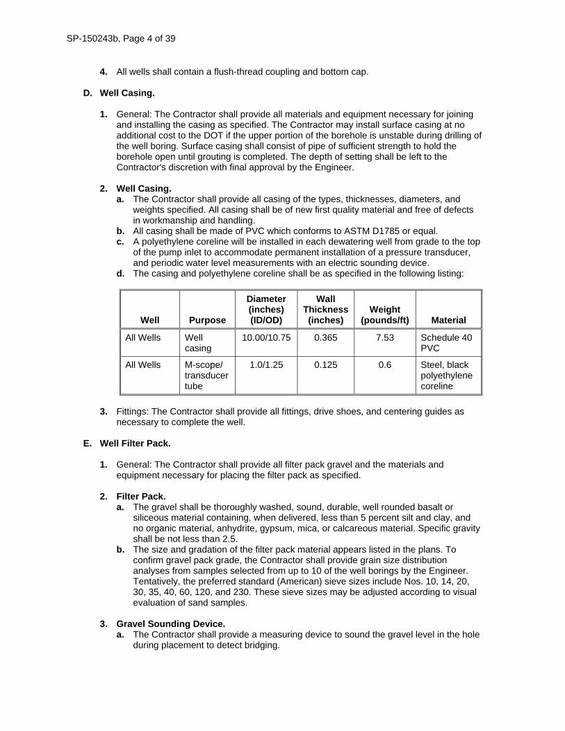
D. Well Casing. 1. General: The Contractor shall provide all materials and equipment necessary for joining
and installing the casing as specified. The Contractor may install surface casing at no additional cost to the DOT if the upper portion of the borehole is unstable during drilling of the well boring. Surface casing shall consist of pipe of sufficient strength to hold the borehole open until grouting is completed. The depth of setting shall be left to the Contractor's discretion with final approval by the Engineer.
2. Well Casing.
a. The Contractor shall provide all casing of the types, thicknesses, diameters, and weights specified. All casing shall be of new first quality material and free of defects in workmanship and handling.
b. All casing shall be made of PVC which conforms to ASTM D1785 or equal. c. A polyethylene coreline will be installed in each dewatering well from grade to the top
of the pump inlet to accommodate permanent installation of a pressure transducer, and periodic water level measurements with an electric sounding device.
d. The casing and polyethylene coreline shall be as specified in the following listing:
Well Purpose
Diameter (inches) (ID/OD)
Wall Thickness (inches)
Weight (pounds/ft) Material
All Wells Well casing
10.00/10.75 0.365 7.53 Schedule 40 PVC
All Wells M-scope/ transducer tube
1.0/1.25 0.125 0.6 Steel, black polyethylene coreline
3. Fittings: The Contractor shall provide all fittings, drive shoes, and centering guides as
necessary to complete the well.
E. Well Filter Pack. 1. General: The Contractor shall provide all filter pack gravel and the materials and
equipment necessary for placing the filter pack as specified.
2. Filter Pack. a. The gravel shall be thoroughly washed, sound, durable, well rounded basalt or
siliceous material containing, when delivered, less than 5 percent silt and clay, and no organic material, anhydrite, gypsum, mica, or calcareous material. Specific gravity shall be not less than 2.5.
b. The size and gradation of the filter pack material appears listed in the plans. To confirm gravel pack grade, the Contractor shall provide grain size distribution analyses from samples selected from up to 10 of the well borings by the Engineer. Tentatively, the preferred standard (American) sieve sizes include Nos. 10, 14, 20, 30, 35, 40, 60, 120, and 230. These sieve sizes may be adjusted according to visual evaluation of sand samples.
3. Gravel Sounding Device. a. The Contractor shall provide a measuring device to sound the gravel level in the hole
during placement to detect bridging.
SP-150243b, Page 5 of 39
b. Prior to installing gravel pack, the hole shall be sounded to the base of the under ream cavity to ensure borehole is open and free of obstructions.
F. Well Development.
1. Swabbing Equipment: The Contractor shall furnish and install the following swabbing
equipment for the dewatering wells, or equal. a. Double swabbing device for 10-inch diameter screens. The swabs shall be separated
by 2 feet of perforated pipe to accommodate air lift pumping while swabbing. Perforations shall occur at 90-degree angles around the pipe.
b. 4-inch diameter piping, to connect the swabbing pipe to the air compressor. c. Swivel joints or flexible connections on the piping to permit vertical and rotational
movement of the swabbing tool. d. An airlift (air-line and eductor pipe) pump (air compressor). e. Miscellaneous connecting pipe and fittings as required.
2. Airlift Development Equipment: Furnish an airlift (air-line and eductor pipe) pump (air
compressor) capable of providing the necessary pressure and flow to pump the wells at rates up to 200 gallons per minute.
3. Sand Content Measuring Device: Provide a sand content measuring device such as a centrifugal sand separator like a Rossum Sand Tester as manufactured by Roscoe Moss Company, Geotech Environmental, Inc., or CGM Mining Solutions, Inc., or equal. The measuring device shall be capable of measuring a minimum sand content of 5 parts per million.
G. Well Cement/Grout Seal. 1. General: The Contractor shall provide all grout and the materials and equipment
necessary for placement of the grout as specified, in accordance with the requirements of the IAC, Environmental Protection Commission (567), Chapter 49, article 49.9(3).
2. Portland cement shall conform to ASTM C150, Type I or II.
H. Submersible Pumps.
1. Definitions – Terminology pertaining to pumping unit performance and construction shall conform to the ratings and nomenclature of the Hydraulic Institute Standards and of AWWA E 101, American National Standard for Vertical Turbine Pumps-Line Shaft and Submersible Types.
2. Complete submersible pump, motor, all cable, and associated downhole components shall be provided as a complete functioning unit in compliance with AWWA E-101 and the applicable Hydraulic Institute Standards from the pump manufacturer. All components shall be manufactured, assembled and tested at the manufacturer's facility.
3. The submersible pump and motor shall be rated for continuous duty and shall be capable of pumping groundwater for dewatering over the specified flow range without surging, cavitation, or vibration. The pump shall not overload the motors for any point on the maximum speed pump performance characteristic curve throughout the entire pump operating range. The service factor for the motor shall not be applied when sizing the motor. To ensure vibration-free operation, all relative components of each pumping unit shall be statically and dynamically balanced. Excessive vibration shall be sufficient cause for rejection of the equipment. The mass of the unit and its distribution shall be such that resonance at normal operating speeds is avoided. The amplitude of vibration as measured at any point on the pumping unit shall not exceed the limits set forth in the
SP-150243b, Page 6 of 39
latest edition of the Hydraulic Institute Standards. All parts of the pump shall be designed to withstand the stresses that will be imposed upon them during their handling, shipping, erection, and operation. The completed unit, when assembled and operating, shall be free of cavitation, vibration, noise, and oil or water leaks over the range of operation.
4. The Contractor shall coordinate pump requirements with drive manufacturer and be responsible for pump and drive requirements.
5. Pump Manufacturers
a. Goulds. b. Grundfos.
6. Unless otherwise specified, materials shall comply with the following requirements.
Materials of construction shall be as follows: a. Strainer: Type 316 Stainless Steel. b. Pump Bowls: Cast Iron, Glass-lined. c. Bowl Wear Rings: Stainless Steel. d. Impellers: Stainless Steel. e. Impeller Wear Rings: Stainless Steel. f. Seal Housings: Stainless Steel. g. Bearing Housings: Silicon Carbide. h. Surface Plate: Fabricated Steel - ASTM A36. i. Pump Shaft: Type 410 or 416 Stainless Steel. j. Bowl Bearings: Bronze.
7. Strength: Castings, fabrications, machined parts and drives shall conform to the industry
standards for strength and durability and shall be rated for continuous duty over the entire operating range.
8. Cast iron: All cast iron used in pump construction shall be close-grained grey cast iron conforming to the requirements of ASTM Designation A48 CL30, or as specified.
9. Fabrications: Fabrications shall conform to the requirements of ASTM Designation A36
for fabricated steel.
10. Nameplates: The pump shall have a Type 316 stainless steel plate permanently attached to the discharge head into which the following information shall be impressed, engraved or embossed: Manufacturer's name, pump size, serial number, impeller diameter, capacity, head rating and speed. Nameplates shall also include information unique to each item of equipment and device to identify its function as described herein. Function nameplates shall be approximately 1 inch by 3 inches if made separately. Letters of function titles shall be not smaller than ¼ inch high.
11. Pump Construction. a. Bowls: The pump bowls shall be free of blow holes, sand holes or other detrimental
defects. b. Sand Collar: The Contractor shall provide a sand collar to prevent sand from entering
the suction bell bearing. c. Pump Shaft: Pump shaft shall be turned and ground. There shall be bronze bearings
above and below each impeller. The length of the top and bottom bearings shall be a minimum of three times the shaft diameter.
d. Impeller: The impeller shall be enclosed and statically balanced and fitted with wear rings.
e. Cap Seal: Pump shall have a discharge case cap to seal off end of pump shaft from any cascading abrasives entrained in the pumped liquid when power is turned off.
SP-150243b, Page 7 of 39
f. Strainer: The strainer will not restrict the flow of water with an open area in excess of four times the throat area of the suction case.
g. Surface Plate: The surface plate shall be made of steel designed to support the total weight of the pump/motor, discharge column full of water, and pump discharge elbow. Surface plate shall be drilled to accommodate the 3 inch pump column pipe, level probe conduit, pump power cord conduit and bolt holes.
h. Column Pipe: Column pipe shall be Schedule 40 black steel pipe, with coupling connections or threaded pipe. Pipe shall be ASTM A53, grade B or equivalent APL. The column pipe shall be provided in 5 foot lengths to set the intake strainer at the necessary depth below the surface plate. Welding of bearings to column is not acceptable. All flange bolts shall be 304 stainless steel and of suitable size to mate flanges.
i. Column Couplings: The upper end of bottom and intermediate column pipes shall be fitted with coupling of ASTM A48, Class 30 cast iron, ductile iron, or steel.
12. Motor. a. General: Oil-filled motor shall be filled with FDA approved food grade, high strength
dielectric mineral oil and have automatic pressure balancing between reservoir and top bearing. The motor shall also have a double mechanical seal located in the top of the motor where its shaft extends through the motor housing.
b. Power Cables. The electrical cable shall be marine submersible type consisting of three stranded conductors of the proper size to carry the full amperes of the motor at rated voltage. The conductors shall be insulated in accordance with IPCEA requirements. The cable shall be supported on the column pipe by means of cable clamps and stainless steel bands at 5 foot intervals. The cable shall terminate in a water proof junction box above the surface plate. Cable size shall be as required and shall be furnished by the pump and motor manufacturer. The cable shall have a plug in terminal to the motor. Motors shall be 460 volts, three-phase, 60 hz.
c. Supplements. Refer to Pump Data Sheets at the end of this section.
d. Accessories. 1) Equipment Identification Plate: 16 gauge stainless steel with ¼ inch die- stamped
equipment tag number securely mounted in a readily visible location. 2) Lifting Lugs: Equipment weighing over 100 pounds. 3) Anchor Bolts: Type 316 stainless steel, sized by equipment manufacturer. 4) Access Pipes: 2 inch I.D., black polyethylene M-scope tubes. 5) Safety Cable: Provide 3/8 inch 316L SST safety cable secured to pump housing
and flange with 3 l 6L SST shackles. e. Level Element/Transmitter, Submersible, Water.
1) General. a) Function: Measure and transmit signal proportional to level. b) Type: Totally submersible pressure sensor (loop powered). c) Parts: Sensor, interconnecting cable, other parts as noted.
2) Service. Fluid: Potable water, unless otherwise noted.
3) Performance. a) Process Range.
(1) As noted. (2) Provide fixed factory range such that noted process range is between
40% and 80% of fixed factory range. b) Accuracy: 0.10 % of full scale, unless otherwise noted. c) Temperature, Operating: -4°F to +140°F. d) Overpressure:
(1) Proof: At least 1.5 times full scale. (2) Burst: At least 2.0 times full scale.
SP-150243b, Page 8 of 39
e) Long Term Stability: +/- 0.10% full scale per year, typical. 4) Features.
a) Sensor. (1) Silicon pressure-sensing element. (2) Wetted parts as required for compatibility with process fluid or as noted,
NEMA 6/IP 68 rating (submersible). (3) Temperature compensation. (4) Dimensions, Nominal.
(a) Diameter: Less than 1 inch. (b) Length: 10 inches maximum.
(5) Loop powered, 9-30V dc. b) Interconnecting Cable.
(1) Length: As required. (2) Teflon sheathed, unless otherwise noted. (3) Kevlar strain relief cord. (4) Integral vent tube.
c) Sensor Termination Enclosure: Not required. Terminate in pump control panel located adjacent to well vault.
d) Accessories. (1) Aneroid Bellows: If noted. Bellows shall be suitable for
application. (2) Cable Hanger, Kellems Type Grip: Required, unless otherwise
noted. (3) Lightning Protection.
(a) Internal (protects against water lightning strike): Required, unless otherwise noted.
(b) External (protects 4 mA to 20 mA dc output): Required, unless otherwise noted.
5) Signal Interface: 4 mA to 20 mA dc output, for load impedance of 0 ohm to 750 ohms, minimum for 24V dc supply without load adjustment.
6) Manufacturers (provided they can furnish the noted options): Endress & Hauser, Waterpilot FMX167A (22mm diameter), Druck PTX1730, or KPSI Model 320.
13. Factory Finishing of Discharge Piping Interior/Exterior and Column Pipe Interior/Exterior. a. Surface Preparation: SP5, White metal blast cleaning. b. Paint Material: NSF Epoxy. c. Minimum Coats - Cover: Three coats, minimum dry film thickness per coat, 3 mil.
14. Source of Quality Control.
a. All tests shall be in accordance with AWWA E-101 and the Hydraulic Institute. b. Factory Inspections: Inspect for required construction, electrical connection, and
intended function. c. Functional Test: Perform manufacturer's standard motor test on equipment.
I. Electrical and Well Pump Control Panel.
1. General.
a. Materials manufactured within scope of Underwriters Laboratories shall conform to UL Standards and have an applied UL listing mark.
b. Products shall comply with all applicable provisions of NFPA 70. c. Like Items of Equipment: End products of one manufacturer in order to achieve
standardization. d. Equipment Finish: Manufacturer’s standard finish color, except where specific color is
indicated.
SP-150243b, Page 9 of 39
2. Conduits. a. PVC Coated Rigid Steel Conduit:
1) Meets requirements of ANSI C80.1 and UL6. 2) Material: Hot-dip galvanized, with PVC coating.
b. PVC Schedule 40 Conduit: 1) Meet requirements of NEMA TC 2 and UL 651. 2) UL listed for concrete encasement, underground direct burial, concealed or direct
sunlight exposure, and 90 degrees C insulated conductors. 3) Furnish without factory-formed bell.
3. Conductors.
a. Insulation for 600 volt rated conductors. 1) No. 8 AWG and Smaller: Type THHN/THWN. 2) No. 6 AWG and Larger: Type XHHW. 3) Flexible Cord and Cable: Type SO, 600 volts.
b. No. 16 AWG, Twisted, Shielded Pair, Instrumentation Cable: Single pair, designed for noise rejection for process control, computer, or data log applications meeting NEMA WC 57 requirements. 1) Outer Jacket: 45 mil nominal thickness. 2) Dimension: 0.31 inch nominal OD. 3) Stranded with 20 AWG, seven strand tinned copper drain wire. Note: Ground
shield in only one location. 4) Color Code: Pair conductors, black and red.
4. Combination Motor Starter.
a. Open style to be installed in separate well pump control panel. b. Rating: See Electrical drawings for motor starter ratings. c. Wiring: All external interface wired to numbered terminal blocks (NEMA type B
wiring). Provide four additional spare terminal blocks for connection of control wiring “passing through” starter.
d. Power Connections: Provide lugs for connecting two No. 6 AWG conductors per phase on line connections. Note that the power to individual panels are “daisy-chained” and therefore two lugs per phase required.
e. Short Circuit Rating: 42,000 amps RMS. f. Control Power Transformer: Fused on primary and secondary (120 Vac secondary).
Provide additional capacity for heat trace in vault associated with well pump.
5. Well Pump Control Panel. a. NEMA 4X aluminum. Hinged blank front, pad lockable. Interior hinged dead front
door with process meter, indicating lights, selector switch, and circuit breaker handle interlocked with door (door cannot be opened unless the circuit breaker is off). The interior of the panel shall contain the combination motor starter and any other additional components. Size as shown on the plans. Note that size on plan is minimum size only. Modify size to accommodate components provided.
b. Indicating lights and selector switch shall be NEMA oil-tight. Indicating lights shall be LED type.
c. Provide sufficient room to the right of the combination starter to allow installation of two No. 2 AWG conductors per phase. (The power to the panels will be “daisy chained”).
d. All conduit entries to panel shall be made at the bottom of the enclosure. Top mounted conduits are unacceptable.
e. Provide process meter to display well level and to provide automatic pump control to maintain well level set points entered on process meter. Process meter shall be similar to Precision Digital Model PD6000-6R5, Automation Direct Model DPM2, or Red Lion Model PAX. Provide meter with two form C relay contact outputs individually programmable. One contact shall be programmed as pump on-off and
SP-150243b, Page 10 of 39
the other contact shall be programmed as high level alarm to activate panel mounted strobe light. Provide meter with 4-20 mA input, integral 24VDC power to power two-wire level element, and individually programmable 4-20 mA output.
f. See control diagram in plans for additional requirements.
J. PVC Pipe. 1. Piping.
a. All header discharge pipe and dewatering well head piping shall be PVC schedule 80 and have nominal diameter as specified in the plans.
b. Materials in contact with water shall conform to NSF 61 acceptance. c. Schedule 80 PVC: Type I, Grade I or Class 12454-B conforming to ASTM D1784 and
ASTM D1785. Pipe shall be manufactured with titanium dioxide for ultraviolet protection.
d. Threaded Nipples: Schedule 80 PVC.
2. Fittings. Schedule 80: ASTM D2466 and ASTM D2467 for socket weld type and Schedule 80 ASTM D2464 for threaded type.
3. Joints.
Solvent socket weld except where connection to threaded valves and equipment may require future disassembly.
4. Flanges.
One-piece, molded hub type PVC flat face flange in accordance with Fittings above, ASME B16.1, Class 125 drilling
5. Bolting.
a. Flat Face Mating Flange and In Corrosive Areas: ASTM A193/A193M, Type 316 stainless steel Grade B8M hex head bolts, ASTM A194/A194M Grade 8M hex head nuts and ASTM F436 Type 3 alloy washers at nuts and bolt heads. Achieve 40% to 60% of bolt minimum yield stress.
b. With Raised Face Mating Flange: Carbon steel ASTM A307 Grade B square head bolts, ASTM A563 Grade A heavy hex head nuts and ASTM F436 hardened steel washers at nuts and bolt heads. Achieve 40% to 60% of bolt minimum yield stress.
6. Gaskets. Flat Face Mating Flange: Full faced 1/8 inch thick ethylene propylene (EPR) rubber, Durlon, 9200W RCA, Garlock Gylon 3510 or pipe manufacturer’s recommendation.
7. Solvent Cement.
Socket type joints shall be made employing solvent cement that meets or exceeds the requirements of ASTM D2564 and primer that meets or exceeds requirements of ASTM F656, chemically resistant to the fluid service and as recommended by pipe and fitting manufacturer.
8. Thread Lubricant.
Teflon Tape.
K. Pipe Supports
1. Saddle Supports, Pedestal Type. a. Minimum standard weight pipe stanchion, saddle, and anchoring flange. b. Nonadjustable Saddle: MSS SP, Type 37 with U-bolt. c. Adjustable Saddle: MSS SP 58, Type 38 without clamp.
SP-150243b, Page 11 of 39
2. Channel Type Support Systems. a. Channel Size: 12 gauge, 1 5/8 inch wide minimum steel. b. Members and Connections: Design for loads using one-half of manufacturer’s
allowable loads. c. Fasteners: Vinyl ester fiber, polyurethane base composite nuts and bolts, or
encapsulated steel fasteners. d. Manufacturers and Products.
1) B-Line; Strut System. 2) Unistrut. 3) Anvil; Power-Strut.
L. Pipe Penetrations through Air Release Valve Manhole, Dewatering Well Vault Box and
Discharge Point at Virden Creek Culvert Modular Mechanical Seal: As specified in Special Provisions for Groundwater Suppression System.
M. Gate Valves.
1. Gate Valve 2 Inches to 24 Inches.
Iron body, bronze mounted, flanged ends, solid wedge gate, nonrising bronze stem, Class 125 rated 125 psi SWP, 200 psi CWP for 2 inches through 12 inches and 100 psi SWP, 150 psi CWP for 14 inches through 24 inches.
2. Globe Valves 2 Inches to 10 Inches. Iron body, bronze mounted, flanged ends, bronze seat, outside screw and yoke, bolted bonnet, Class 125 rated 125 psi SWP/200 psi CWP, complies with MSS SP-85 Type 1.
3. Ball Valves 3 Inches and Smaller for General Water and Air Service. Two-piece, standard port, NPT threaded ends, bronze body and end piece, hard chrome-plated solid bronze or brass ball, RTFE seats and packing, blowout-proof stem, adjustable packing gland, zinc-coated steel hand lever operator with vinyl grip, rated 600-pound WOG, 150-pound SWP, complies with MSS SP-110.
4. Check Valves (at dewatering well), Type V604 Check Valve 2 1/2 Inches to 12 Inches. Flanged end, cast-iron body, bronze mounted swing type, solid bronze or cast-iron disc, bronze seat ring, rated 125-pound SWG, 200-pound WOG.
5. Air Release Valves, Type V744, 1/2 Inch to 2 Inches a. Suitable for water service, automatically exhaust small amounts of entrained air that
accumulates in a system. In CLOSED position, seat against resilient seat to prevent water leakage.
b. Rated 150 psi working pressure, cast-iron or ductile iron body and cover, stainless steel float and trim, NPT threaded inlet and outlet, built and tested to AWWA C512.
6. Check Valves (at temporary dewatering discharge points): Tideflex inline check valve.
N. Dewatering Well Vault Box.
1. Dewatering Well Vault shall be precast rectangular concrete vault as specified below.
2. Comply with ASTM C858.
3. Reinforcing Steel:
a. Deformed Bars: ASTM A615/A615M, Grade 60.
SP-150243b, Page 12 of 39
b. Welded Wire Fabric: ASTM A497/A497M.
4. Nominal Dimensions: As shown on plans.
5. Construction: Rigid type and behave monolithically.
6. Design Loads: As determined by ASTM C857.
7. Blockouts for penetrations shall be as shown on plans.
8. Sealant: Nonswelling preformed joint sealants to provide a lasting, watertight bond.
9. Mortar: Comply with ASTM C387/C387M, Type S or use Type I grout.
10. Sidewalk Doors. a. Load Capacity: 300 pounds per square foot with maximum deflection of 1/150th of
span. b. Access door leaf: 1/4 inch. c. Channel Frame: 1/4 inch-thick extruded aluminum trough frame with continuous
anchor flange around perimeter. Weld 1 1/2 inch diameter drain coupling, and drain pipe, to frame trough at front right corner, unless indicated otherwise on plans.
d. Door Hinges: Heavy-duty brass or stainless steel with stainless steel pins through-bolted to cover plate with tamper-proof stainless steel bolts flush with top of cover and to outside leg of channel frame with stainless steel bolts and locknuts.
e. Lifting Mechanism: Stainless steel compression lift springs enclosed in telescoping vertical housing or stainless steel torsion lift springs.
f. Hold-Open Arm: Locks automatically in open position. Disengages with slight pull on vinyl grip with one hand. Door can be easily closed with one hand by pulling forward and down on vinyl grip.
g. Snap Lock: Stainless steel snap lock mounted on bottom of door leaf with removable topside key wrench and inside fixed lever handle. Threaded plug for flush outside surface with key wrench removed.
O. Manholes for Air Release Valves.
Manholes for Air Release Valves shall be precast circular concrete manholes in accordance with Article 4149.04 of the Standard Specifications.
P. Concrete Anchors.
1. Cast-In-Place Anchor Bolts: Headed type, unless otherwise shown on plans. Material
Type: 316 SST.
2. Post-Installed Concrete Anchors: Material shall be 316 SST. Current ICC-ES Report indicating acceptance per IBC 2015 for anchors at structural applications in cracked concrete. Anchors shall be suitable for long-term loads. Use adhesive anchors for all applications except overhead anchorage. Use expansion anchors for overhead anchorage.
Q. Trench Backfill for PVC Pipe.
1. Pipe Bedding, Haunch Support and Primary and Secondary Backfill: Use Suitable Class
II Material in accordance with Article 2552.02, C.1 of the Standard Specifications. Maximum particle size shall not exceed 0.75 inch.
2. Final Trench Backfill.
SP-150243b, Page 13 of 39
a. Use Suitable Backfill Material in accordance with Article 2552.02, A, 1, a of the Standard Specifications.
b. For pipe sections crossing US-63, between temporary dewatering wells DW-1 and DW-22, and between DW-13 and the temporary discharge point at Virden Creek Enclosure, use Suitable Class II Material in accordance with Article 2552.02, C, 1 of the Standard Specifications.
R. Heat Tracing and Insulation.
1. Heat Tracing.
a. System Design Requirements 1) Heating load shall be calculated based upon a 50°F delta, 20 mph wind if pipes
are located outdoors, insulation as specified, and shall include a 10% safety factor.
2) Heat loss calculations shall be based on Institute of Electrical and Electronics Engineers (IEEE) 515, Equation 1, Page 19.
b. Electrical Heating Tape 1) Cable: Self-limiting, parallel circuit construction consisting of continuous inner
core of variable resistance conductive heating material between two parallel copper bus wires. Provide tinned copper braid for PVC, FRP, and stainless steel pipe applications.
2) UL Listing: Listed as self-limiting pipe tracing material for pipe freeze protection application in ordinary conditions.
3) Maximum Maintenance Temperature: 150°F. 4) Maximum Intermittent Temperature: 185°F. 5) Service Voltage: As indicated by branch circuits provided for heat tracing on the
plans. 6) Manufacturers and Products:
a) Raychem; BTV-CR. b) Thermon; BSX. c) Nelson; CL1-J1 or L1-J1.
c. Connection System 1) Rating: NEMA 250, Type 4 and Factory Mutual approved. 2) Operating Monitor Light: Furnish with each circuit power connection kit to indicate
when heat tracing is energized. 3) Manufacturers and Products.
a) Power Connection Kit. (1) Raychem; JBS-100. (2) Thermon; PCA-1-SR or DP-L. (3) Nelson; PLT-BC.
b) Splice Kit. (1) Raychem; S-150. (2) Thermon; PCS-1-SR. (3) Nelson; PLT-BS.
c) Tee Kit. (1) Raychem; T-100. (2) Thermon; DS-S. (3) Nelson; PLT-BY.
d) End Seal Kit. (1) Raychem; E-150. (2) Thermon; DE-S. (3) Nelson; LT-ME.
e) Lighted End Seal Kit. (1) Raychem; E-100-L. (2) Thermon; DLS. (3) Nelson; LT-L.
SP-150243b, Page 14 of 39
d. Securing Tape 1) Plastic Piping Systems.
a) Type: Aluminum foil coated adhesive tape. b) Manufacturers and Products.
(1) Raychem; AT-180. (2) Thermon; AL-20P. (3) Nelson; AT-50.
2) Metallic Piping Systems. a) Type: Glass or polyester cloth pressure sensitive tape. b) Manufacturers and Products.
(1) Raychem; GS54 or GT66. (2) Thermon; PF-1. (3) Nelson; GT-6 or GT-60.
e. Pipe Mounted Thermostat. 1) Type: Fixed, nonadjustable, set at 40°F. 2) Sensor: Fluid-filled with 3 foot capillary. 3) Enclosure: Glass-filled nylon, NEMA 250, Type 4X weatherproof with gasketed
lid. 4) Switch: SP-ST, UL listed, rated 22 amps, 120 to 240V ac.
f. Ambient Thermostat. 1) Type: Adjustable setting (15°F to 140°F). 2) Sensor: Fluid-filled probe. 3) Enclosure: Epoxy-coated NEMA 250, Type 4X aluminum enclosure with exposed
hardware of stainless steel. 4) Switch: SP-DT, UL or FM listed, rated 22 amps, 125 to 250V ac.
2. Insulation.
a. Fiberglass. 1) Material: UL rated, preformed, sectional bonded fiberglass per ASTM C585 with
factory applied, Kraft paper with aluminum foil vapor barrier jacket with pressure-sensitive, self-sealing lap.
2) Insulation Temperature Rating: 0°F to 850°F. 3) Conductivity in accordance with ASHRAE 90.1 and maximum numerical value of
0.23 Btu-in./hr-square foot °F at 75°F. 4) Jacketing per ASTM C1136 with minimum water vapor transmission for jacket of
0.02 perm-inch per ASTM E96/E96M. Furnish with no jacket if field finish system specified.
5) Joints: Matching pressure-sensitive butt strips for sealing circumferential joints. 6) Flame Spread Rating: Less than 25 per ASTM E84. 7) Smoke Developed Index: Less than 50 per ASTM E84.
b. Insulation at Pipe Hangers and Supports. Nonmetallic Pipe: High-density insert, thickness equal to adjoining insulation of Type 3 or other rigid insulation or manufactured pre-insulated pipe hanger and insulation shield. Extend insert beyond shield.
c. Insulation Finish Systems 1) Aluminum Roll Jacketing: For straight run piping, wrought aluminum Alloy 3003,
5005, 1100, or 3105 to ASTM B209 with H-14 temper, in accordance with ASTM C1729, minimum 0.016 inch thickness, with smooth mill finish.
2) Vapor Barrier: Provide factory applied vapor barrier, heat and pressure bonded to inner surface of aluminum jacketing.
3) Fitting Covers: Material as for aluminum roll jacketing, premolded, one or two piece covers, which includes elbows, tee/valves, end caps, mechanical line couplings, and specialty fittings.
S. Temporary Piezometer.
SP-150243b, Page 15 of 39
1. Riser pipe for piezometers shall consist of schedule 40 or thicker PVC pipe with flush threaded couplings. All PVC pipe shall have a nominal diameter of 2 inches. A PVC cap for the riser shall be provided. Sensing tips shall consist of 2 inch ID factory-slotted PVC threaded pipe, with 0.02 inch size openings, 60 inches in length.
2. A valve box assembly or steel casing with protective cover shall be provided for piezometers (PZ). Each protective cover shall be 2 inches larger in inside diameter than the rod or riser pipe within, or a minimum of 4 inches, whichever is greater. The valve box shall have a minimum depth below ground surface of 1.5 feet. The valve box shall have a bolting cover.
T. Well Abandonment. Well plugging material shall satisfy the requirements in the Iowa Administrative Code (IAC), Environmental Protection Commission (567), Chapter 39.
U. Site Restoration.
The Contractor shall backfill trenches with Suitable Class II or Class III Backfill Material in accordance with Article 2552.02, C of the Standard Specifications.
150243b.03 CONSTRUCTION.
A. Submittal
1. Qualifications: The Contractor shall submit the resumes of the personnel and the Contractor that will perform the work and submit qualifications for the Contractor and Contractor’s personnel that meet the requirements of Section 1.F, “Qualification”. In addition, the Contractor shall submit required certifications.
2. The Contractor shall submit detailed work plan prior to mobilization. At a minimum, the work plan shall include the following items. a. Proposed well, vault box, and air release valve manhole location plan and layout. b. Proposed header discharge pipe layout and profile. c. Overall construction sequence of temporary dewatering system. d. Drilling and well installation sequence. e. Any proposed earthwork associated with access and installation of temporary
dewatering system. f. Well abandonment plan and detail. g. Well conversion plan and detail for wells that will be converted to permanent
groundwater monitoring wells. h. Site restoration plan.
3. Valve Box and Air Release Valve Manhole: The Contractor shall provide shop drawings
for precast structures showing general geometry, total depth, relative elevations and orientation of all connecting pipes and connection detail between precast segments. Shop drawings shall also include details of cover, invert and steps.
4. Well Screen Assembly: The Contractor shall provide specification sheets for well screen and riser.
5. Well Casing: The Contractor shall provide shop drawings and/or catalog cuts for well
casing for review and approval.
6. Well Filter Pack. a. The Contractor shall submit grain size analyses for filter pack gravel for review and
approval. b. The Contractor shall submit a 5-pound sample for each of the proposed filter pack
material for approval prior to delivery of filter pack to the site.
SP-150243b, Page 16 of 39
7. Well Development. a. The Contractor shall submit a detailed description and supplementary information on
proposed methods of development other than those mentioned in this special provision.
b. The Contractor shall provide a list of at least two references where the Contractor's proposed method of development has been successfully applied to similar type screened dewatering wells.
8. Submersible pumps: The Contractor shall submit the following for review and approval prior to incorporation of the work: a. All new pumping equipment shall be tested at the factory. The manufacturer shall
provide a factory certified pump curve of the actual pump intended for installation. b. Make, model, weight, and horsepower of each equipment assembly. c. Complete catalog information, descriptive literature, specifications, and identification
of materials of construction. d. Performance data curves showing total dynamic head, flowrate, brake horsepower
demand, shutoff head, NPSH and pump efficiency over the entire operating range of the pump, from shutoff to maximum capacity. Indicate separately the head, capacity, horsepower demand, overall efficiency, and minimum submergence required at the guarantee point.
e. Pump maximum downthrust or upthrust in pounds. f. Detailed structural, mechanical and electrical drawings showing the equipment
dimensions, size, and locations of connections and weights of associated equipment. g. Power and control wiring diagrams, including terminals and numbers. h. Complete motor nameplate data, as defined by National Electrical Manufacturer's
Association (NEMA), MG 1, Motors and Generators, motor manufacturer, and including any motor modifications.
i. Motor data, including the manufacturer; the minimum guaranteed efficiency and power factor at full load, % load, and Yi load; locked rotor current in amps; full load current in amps; the motor speed in rpm; service factor; and mounting details.
j. Thrust bearing life. k. Type of thrust bearing and guide bearing. l. Assembly and Installation Drawings. After the above equipment submittals have been
approved, the Contractor shall submit complete fabrication, assembly, pump column, and installation drawings, together with detailed specifications and data covering materials of construction, weight of the pump, power drive assembly, parts, devices, wiring diagrams, and other accessories forming a part of the equipment furnished, for approval. Drawings, specifications, and other data required to be submitted shall include, but shall not be limited to, the following: 1) Materials of pump construction including shafts, bearings, impellers, castings,
pump base, stuffing boxes, and shaft guards. 2) Electric motor data including size, make, type designations, wiring diagram of
thermal protection, description and rating of motor moisture sensing system, and mounting details.
m. Factory, Functional and Performance Test Reports and Logs. n. Manufacturer's Certification of Compliance that the factory finish system is identical
to the requirements specified herein. o. Special shipping, storage and protection, and handling instructions. p. Manufacturer's printed installation instructions. q. Manufacturer's Certificate of Proper Installation. r. Suggested spare parts list to maintain the equipment in service for a period of 1 year
and 5 years. Include a list of special tools required for checking, testing, parts replacement, and maintenance with current price information.
s. List of special tools, materials, and supplies furnished with equipment for use prior to and during startup and for future maintenance.
SP-150243b, Page 17 of 39
9. Electrical and Well Pump Control Panel: The Contractor shall submit shop drawings for the following for review and approval prior to incorporation of the work: a. Conduits. b. Conductors. c. Combination motor starters including circuit breaker handle interlocked with dead
front door. d. Well pump control panels. e. Process meters. f. Indicating lights and selector switches. g. Alarm horn. h. Level element.
10. Monitoring Results of Temporary Piezometers: The Contractor shall submit readings
within 24 hours after the readings are taken.
B. Well Drilling Mobilization and Cleanup. 1. General.
a. The Contractor shall install temporary dewatering wells DW-1 through DW-22 at the locations shown in the plans.
b. Bidders are advised to carefully inspect the existing facilities before preparing their proposals.
c. Set up well drilling equipment in the areas designated by the Engineer. Accomplish all required work in accordance with applicable portions of this Special Provision.
2. Onsite Utilities: The Contractor is responsible for finding locally or providing potable water for drilling.
3. Contamination Precautions: The Contractor shall avoid contamination of the project area. Do not dump waste oil, rubbish, or other waste materials on the ground.
4. Cleanup of Construction Areas.
a. Upon completion and acceptance of the wells, the Contractor shall remove from the site the drill rig and equipment, complete, and all debris, unused materials, temporary construction buildings, and other miscellaneous items resulting from or used in the operations; replace or repair any facility which has been damaged during the construction work; and restore the site as nearly as possible to its original condition.
b. The Contractor is responsible for disposing of all drilling fluids.
C. Drilling.
1. General. a. The Contractor shall notify the Engineer one week prior to starting drilling. b. The Contractor shall provide at all times a thoroughly experienced, competent, and
certified driller during all operations at the drill site. c. The borehole shall be drilled so as to permit the installation of the casing and
screen(s) straight and plumb to the tolerances specified in this Special Provision. d. The Contractor shall drill and construct the 10 inch diameter dewatering wells as
follows: 1) The Contractor will install 10 inch diameter dewatering wells penetrating through
soil only or soil and bedrock. These wells will require a minimum nominal drill-hole diameter of 14 inches to the bottom of dewatering well elevations shown on the plans.
2) Well construction details are shown on the plans. Well construction intervals on the plans are based on evaluation of local geology. Actual settings may require adjustment in the field.
SP-150243b, Page 18 of 39
3) During the drilling, the Contractor shall collect ditch samples of drill cuttings every 5 feet for visual soil classification and generate drill logs.
4) The use of mud circulation pits is not allowed. The Contractor shall provide the necessary equipment, such as frac tanks, for mud circulation operation.
e. Use drilling fluids and additives specifically approved by the Engineer shall be used. The Contractor shall achieve consistent mud control and circulation to lift cuttings from the borehole and prevent caving. The Contractor shall minimize the introduction of non-native clays, additives, and water into the formation during drilling and well development.
2. Abandoned Hole. a. If the Contractor fails to complete the test hole to the total depth as specified by the
Engineer, or fails test requirements as specified, or if the casing or screen is broken or collapses, the well will not be considered satisfactory and the well will be abandoned and plugged by the Contractor at the Contractor’s own expense, according to the Iowa Administrative Code (IAC), Environmental Protection Commission (567), Chapter 39.
b. The Contractor may, at their own expense, salvage any casing installed in the abandoned hole.
c. The Contractor shall then move to another designated location approved by the Engineer and drill a second well in accordance with this Special Provision.
3. Compliance with Governmental Regulations: The Contractor shall construct the well in strict conformance with all laws, rules, regulations, and standards related to the construction of wells in the State of Iowa and County of Black Hawk.
4. Protection of Water Quality: The Contractor shall take all necessary precautions to prevent contaminated water, gasoline, or other deleterious substances from entering the well, either through the opening or by seepage through the ground surface. The Contractor shall maintain these precautions during and after construction of the well until accepted by the Iowa DOT.
5. Driller's Log and Other Logs.
a. Lithologic and drilling rate logs shall be maintained by the driller, recording the type of material encountered in the well borings, drilling times, depth of the hole, and thickness of the geologic unit. The Contractor shall prepare logs for every well boring. A record of daily activities shall be kept by the Contractor and shall be furnished to the Engineer's representative at the completion of the Contract. The Engineer will approve the manner in which the logs are kept. All logs shall be available to the Engineer for their inspection at all times during the life of the Contract.
b. The driller's log and time drilling log shall be turned over to the Engineer at the conclusion of the project.
6. Disposal of Cuttings and Water.
a. The Contractor is responsible for removing drill cuttings from the site. b. Disposal of drilling and development fluids is the responsibility of the Contractor.
7. Standby Time.
a. During the progress of well construction and sampling operations under this Special Provision, it may be necessary for the Iowa DOT to perform work of a nature that will require the services of the drilling crew and drilling equipment, or work that may require the crew and equipment to stand idle during normal working hours. In such an event, the Engineer shall order the Contractor to furnish assistance or to cease operations, and will state the anticipated extent or duration thereof. The Contractor shall promptly furnish such assistance, or cease operations, and shall receive reimbursement therefore as set forth in the Bid Schedule.
SP-150243b, Page 19 of 39
b. Idle time of the drilling crew and equipment, during normal working hours, not ordered in writing by the Engineer shall not be reimbursable under this Contract.
c. Payment for standby time shall be granted only for delays caused by the Iowa DOT. No standby will be paid for any delays caused by driller's error, repairs to equipment, or for any delay due to the Contractor's inability to procure, provide, or maintain the necessary equipment, materials, or supplies to enable the job to continue without delays. Periods of down time caused by inclement weather shall not be charged as standby time. Work stoppage for the 24 hour minimum setting time of cement grout shall not be charged as standby time.
D. Well Screen Assembly.
1. The Contractor shall install the well screen assemblies and fittings in conformance with
the well screen manufacturer's recommendations.
2. After setting the well screen assembly, the Contractor shall measure from the ground surface to the bottom of the screen to assure a depth consistent with the schedule listed in the Plans. Further, the depth of the under ream cavity outside the screen shall be sounded to total depth before adding well filter pack.
E. Well Casing.
1. The Contractor shall install specified casing in hole plumb and straight.
2. All casing shall be installed by a method appropriate to the attached well construction
drawing, as selected by the Contractor and reviewed by the Engineer.
3. Casing lengths featured in the Plans are tentative; final casing lengths shall be determined in the field by the Engineer.
4. Casing lengths shall be joined watertight by a method appropriate to the material used, as selected by the Contractor, so that the resulting joint shall have the same structural integrity as the casing itself.
5. If threaded and coupled joints are used, couplings shall be API or equivalent, made up so that when tight, all threads will be buried in the lip of the coupling.
F. Well Filter Pack.
1. General: If high viscosity drilling fluid has been used in drilling, it shall be thinned with
water prior to placement of gravel.
2. Placing Gravel: The gravel shall be introduced at a metered uniform rate in a manner that will allow even placement of the gravel. Every precaution shall be taken to ensure placement of the gravel pack continuously from the bottom of the well to a point 10 feet above the well screen without separation or bridging of the materials as they are introduced into the well. During placement of the gravel, the top of the gravel shall be continuously sounded to measure its rate of rise and to determine if bridging is occurring. At the discretion of the Engineer, gravel may be added to top off the packs in the dewatering wells which may have undergone significant settlement during development.
G. Well Development.
1. The total development time for each well shall run 8 hours. The Engineer shall be the
sole judge to the termination of development on each well, and may alter development time.
SP-150243b, Page 20 of 39
2. The Contractor shall provide a combination of two methods of mechanical development, which shall include 1) swabbing with a double swab or surge block, 2) airlift pumping, or 3) other method to be approved by the Engineer. Also, some polyphosphate treatment may be applied to loosen clay minerals around the borehole.
3. Swabbing and Airlift Pumping.
a. The Contractor shall swab the screens by vigorously moving the swabbing tool up and down the well while simultaneously airlift pumping.
b. Development shall start at the bottom of the well screen and proceed upward. One 3 foot section of well screen will be developed at a time. Discharge from the well will run clear and free of fines before proceeding up the well to the next section of screen.
c. If the well screen sump or tailpipe fills with fines prior to completion of swabbing, the swabbing equipment shall be removed and the well cleaned to the bottom before resuming swabbing.
d. After swabbing and airlift pumping, the well shall be sounded and cleaned to the bottom by airlift pumping, bailing, or other equal method.
e. The Contractor shall operate the swabbing equipment continuously at such rates of discharge and for such periods of time as determined by the Engineer. The Engineer will determine when swabbing is complete.
4. Airlift Development. a. The Contractor shall develop all of the wells by using the airlift pump with an air-line
capable of reaching the bottom of the well and using the well casing as the eductor pipe. A smaller diameter eductor pipe may also be needed to increase uphole velocities.
b. The equipment shall be assembled and operated so that the air-line is capable of reaching the bottom of the well and may be placed inside of the swabbing tool or a smaller diameter eductor pipe. The bottom of the air-line and eductor pipe shall be capable of being moved the entire length of the well screen.
c. After the specified period of airlift development, if the well has filled with fines, the air-line shall be lowered to the bottom of the well and operated so a sufficient uphole velocity is achieved to remove the fines.
d. The Contractor shall operate the airlift development equipment continuously at such rates of discharge and for such periods of time as determined by the Engineer. The well shall be developed until the water is free from sand, silt, and turbidities as observed by the Engineer. The Engineer will determine when development is complete.
5. Overpumping Development. a. Development by overpumping shall follow airlift pumping. b. The Contractor shall provide a vertical turbine pump that can be pumped at rates up
to 200 gallons per minute for overpumping development. The suction flange for the development pump shall be set at 2 feet above the screen to ensure pump bowls are not dewatered at elevated, development pumping rates.
c. A 1/2 inch diameter black polyethylene pipe shall be attached to the pump column, extending from the top of the uppermost pump bowl to 1 foot above the top of the well casing. This pipe will provide an access port for a water level indicator or pressure transducer for collecting water level elevations during development and specific capacity testing. This access piping can be reused when the permanent pump is reinstalled.
d. During overpumping redevelopment, the wells shall be surged by turning the pump on and off over a short time period. This type of development shall continue until discharge runs clear and free of sediment. After surging, the well shall be pumped at a rate that is approximately 120% to 150% of its operating rate (pump design flow rate) as shown in the Plans. Overpumping shall continue for at least 4 hours, and
SP-150243b, Page 21 of 39
until discharge is free of turbidity. The Engineer will determine when development is complete.
e. The Contractor shall be responsible for disposing of discharge effluent during over pumping. Typically, development effluent can be discharged to the ground surface adjacent to the site.
6. Development Water Containment and Disposal. a. The method of containment shall completely contain swabbing or development water
without affecting the effectiveness of the development method. b. Containment shall minimize contact of the water with workers, Engineer, other
people, pets, or animals. c. Disposal of the development water from swabbing and airlift pumping is the
responsibility of the Contractor.
H. Well Grout Seal.
1. Neat Cement Grout. a. Neat cement grout is required and shall consist of cement and water with not more
than 6 gallons of water per 1 cubic foot of cement. b. Sufficient annular opening shall be provided to permit a minimum 2 inches of grout
around the protective casing, including couplings, if used.
2. Additives. a. The use of special cements, bentonite to reduce shrinkage or other admixtures
(ASTM C494) to reduce permeability, increase fluidity and/or control set time, and the composition of the resultant slurry shall be reviewed by the Engineer.
b. Consistency and method of mixing shall be reviewed by the Engineer prior to grouting.
3. Placing. The method of grout placement shall be reviewed by the Engineer. If grouting below the water table, no method will be permitted that does not force grout from the bottom of the space to be grouted to the surface. The grouting shall be done continuously and in such a manner as will ensure the entire filling of the annular space in one operation. When grouting, the bottom of the tremie pipe will be set 6 inches above the top of the filter pack and withdrawn in increments as grout fills the annular space. No drilling operations will be permitted until the grout has cured. Curing time shall be a minimum of 24 hours.
I. Submersible Pumps.
1. Installation.
a. The Contractor shall install submersible pumps in accordance with manufacturer's printed instructions and plans.
b. The Contractor shall provide level sensor to pump setting. c. Suction and discharge piping shall be connected without imposing strain to pump
flanges. d. Anchor Bolts shall be placed accurately using equipment templates.
2. Field Finishing.
The Contractor shall touch up paint as required.
3. Field Quality Control. a. The Contractor shall conduct functional tests on each pump as follows:
1) Alignment: Test complete assemblies for correct rotation, proper alignment and connection, and quiet operation.
2) Vibration Test.
SP-150243b, Page 22 of 39
a) Test with unit installed and in normal operation, and discharging to the connected piping systems at rates over all operating speeds as approved by Engineer, and with actual building structures and foundations provided shall not develop vibration exceeding the 80% of the limits specified in HIS 9.6.4.
b) If unit exhibits vibration in excess of limits specified, adjust or modify as necessary. Unit that cannot be adjusted or modified to conform as specified shall be replaced.
3) Flow Output: Measured by plant instrumentation. 4) Test for continuous 3 hour period.
b. Performance Test: In accordance with Hydraulic Institute Standards.
4. Manufacturer’s Services. A Manufacturer's Representative shall be present on site or at a classroom designated by the Contracting Authority, for minimum person-days listed below, travel time excluded: a. 1 person-days for installation assistance and inspection. b. 1 person-days for functional and performance testing and completion of
Manufacturer's Certificate of Proper Installation. c. 2 person-days for post-startup training of Iowa DOT personnel. Training shall not
commence until an accepted detailed lesson plan for each training activity has been reviewed by Iowa DOT.
5. Supplements.
The supplements listed below, following "End of Section," are a part of this Specification. a. Pump Data Sheets. b. Induction Motor Data Sheet.
J. Air Release Manhole and Dewatering Well Vault Box.
The Contractor shall perform installation in accordance with Section 2435 of the Standard Specifications.
K. Pipe Penetrations through Air Release Valve Manhole, Dewatering Well Vault Box and
Discharge Point at Virden Creek Culvert.
1. The Contractor shall form or core circular opening and install pipe with modular mechanical seal in accordance with the manufacturer recommendations.
2. At each of the temporary dewatering discharge points: a. Core at the same tapping locations proposed for the permanent storm sewer. b. Divert flow in the Virden Creek Enclosure as necessary to accomplish the work.
Obtain approval of the diversion plan from the Engineer. c. Install pipe flush with inside wall of the Virden Creek Enclosure structure. d. Install Tideflex inline check valve on the temporary discharge header pipe for
backflow prevention from Virden Creek Enclosure.
L. Valves Installation.
1. The Contractor shall install valves so handles operate from fully open to fully closed without encountering obstructions.
2. The Contractor shall install valves in locations specified in the plans for easy access for routine operation and maintenance.
3. The Contractor shall install valves in accordance with manufacturer’s recommendations.
M. Trench Excavation and Backfill for Header Discharge Pipe and Other Below-Grade
Conduits.
SP-150243b, Page 23 of 39
Shall be performed in accordance with Section 2552 of the Standard Specifications, except:
1. Do not allow material to free fall into the pipe zone until after at least 2 feet of material has been provided over top of pipe.
2. Do not use power driven impact type compactors for compaction until at least 4 feet of material is placed over top of pipe.
N. Buried Pipe Installation.
1. Placement General.
a. Keep trench dry until pipe laying and joining are completed. b. Exercise care when lowering pipe into trench to prevent twisting or damage to pipe. c. Measure for grade at pipe invert, not at top of pipe. d. Excavate trench bottom and sides of ample dimensions to permit visual inspection
and testing of entire flange, valve, or connection. e. Prevent foreign material from entering pipe during placement. f. Close and block open end of last laid pipe section when placement operations are
not in progress and at close of day’s work. g. Lay pipe upgrade with bell ends pointing in direction of laying. h. Deflect pipe at joints for pipelines laid on a curve using unsymmetrical closure of
spigot into bell. If joint deflection of standard pipe lengths will not accommodate horizontal or vertical curves in alignment, provide: 1) Shorter pipe lengths. 2) Special mitered joints. 3) Standard or special fabricated bends.
i. After joint has been made, check pipe alignment and grade. j. Place sufficient pipe zone material to secure pipe from movement before next joint is
installed. k. Prevent uplift and floating of pipe prior to backfilling.
2. PVC Pipe Placement.
a. Lay pipe snaking from one side of trench to other. b. Offset: As recommended by manufacturer for maximum temperature variation
between time of solvent welding and during operation. c. Do not lay pipe when temperature is below 40°F, or above 90°F when exposed to
direct sunlight. d. Shield ends to be joined from direct sunlight prior to and during the laying operation.
O. Electrical and Well Pump Control Panel.
1. General.
a. Workmanship shall comply with all applicable provisions of NECA 5055. b. Install materials and equipment in hazardous areas in a manner acceptable to
regulatory authority having jurisdiction for the class, division, and group of hazardous area indicated.
c. Ground equipment, enclosures, and complete conduit system securely in accordance with applicable sections of NFPA 70.
2. Motor Starter. Field adjust trip settings of motor starter magnetic circuit breakers in accordance with manufacturer's instructions.
3. Conduits and Fittings.
a. General. 1) Do not install crushed or deformed raceways.
SP-150243b, Page 24 of 39
2) Avoid trapped raceways in damp and wet locations. 3) Prevent plaster, dirt, or trash from lodging in raceways, boxes, fittings, and
equipment during the course of construction. Clear clogged raceways of obstructions.
4) Secure conduits entering cabinets, pull boxes or outlet boxes with galvanized knockouts and bushings, on both sides of box wall.
b. PVC Coated Rigid Steel Conduits. All exposed conduits shall be PVC coated rigid steel. When transition from below grade to above grade, use PVC coated rigid steel from a minimum 12 inches below grade.
c. PVC Conduits. Use only in direct buried applications. Minimum depth 18 inches. May be routed with well pumps discharge piping.
4. Conductors.
a. Conduit system shall be complete prior to drawing conductors. b. Lubricate prior to drawing into conduit. Lubrication type shall be as approved by
conductor manufacturer. c. Identification:
1) Where two or more conduits run to a single outlet box, color code each circuit as a guide in making connections.
2) Carry colors continuously throughout the system if more than one multiwire branch circuit is carried through a single raceway.
3) Connect circuit conductors of same color to same underground feeder conductor throughout installation.
4) Colors. a) Neutral Wire: White. b) Ground Wire: Green.
5. Protection Following Installation.
a. Protect materials and equipment from corrosion, physical damage, and the effects of moisture on insulation.
b. Cap conduit runs during construction with manufactured seals.
P. Pipe Heat Tracing and Insulation.
1. General. a. The Contractor shall install all trace heating in accordance with the manufacturer’s
instructions and recommended practices. b. The Contractor shall provide insulation as specified over all pipe heat tracing. c. Metallic structures or materials used for support of heating cable or on which it is
installed in accordance with applicable codes shall be grounded. d. Wiring between power connection points of heat tracing cable branch lines shall be
provided by heat tracing system supplier. e. The Contractor shall provide end of circuit pilot lights on heat tracing circuits for
buried piping.
2. Electrical Heating Tape. a. The Contractor shall determine required length of electrical heating tape by
considering length of circuit, number and type of fittings and fixtures, design heating load, and heating tape output.
b. Where design heating load exceeds heating tape capacity, install by spiraling. c. The Contractor shall derate heating tape capacity when installed on plastic piping. d. The Contractor shall install trace heating on services as follows:
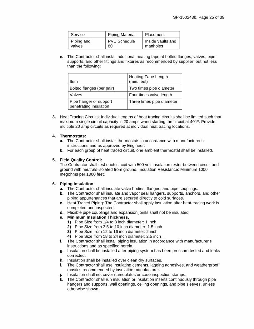
SP-150243b, Page 25 of 39
Service Piping Material Placement
Piping and valves
PVC Schedule 80
Inside vaults and manholes
e. The Contractor shall install additional heating tape at bolted flanges, valves, pipe
supports, and other fittings and fixtures as recommended by supplier, but not less than the following:
Item Heating Tape Length (min. feet)
Bolted flanges (per pair) Two times pipe diameter
Valves Four times valve length
Pipe hanger or support penetrating insulation
Three times pipe diameter
3. Heat Tracing Circuits: Individual lengths of heat tracing circuits shall be limited such that
maximum single circuit capacity is 20 amps when starting the circuit at 40°F. Provide multiple 20 amp circuits as required at individual heat tracing locations.
4. Thermostats: a. The Contractor shall install thermostats in accordance with manufacturer’s
instructions and as approved by Engineer. b. For each group of heat traced circuit, one ambient thermostat shall be installed.
5. Field Quality Control:
The Contractor shall test each circuit with 500 volt insulation tester between circuit and ground with neutrals isolated from ground. Insulation Resistance: Minimum 1000 megohms per 1000 feet.
6. Piping Insulation
a. The Contractor shall insulate valve bodies, flanges, and pipe couplings. b. The Contractor shall insulate and vapor seal hangers, supports, anchors, and other
piping appurtenances that are secured directly to cold surfaces. c. Heat Traced Piping: The Contractor shall apply insulation after heat-tracing work is
completed and inspected. d. Flexible pipe couplings and expansion joints shall not be insulated e. Minimum Insulation Thickness.
1) Pipe Size from 1/4 to 3 inch diameter: 1 inch 2) Pipe Size from 3.5 to 10 inch diameter: 1.5 inch 3) Pipe Size from 12 to 16 inch diameter: 2 inch 4) Pipe Size from 18 to 24 inch diameter: 2.5 inch
f. The Contractor shall install piping insulation in accordance with manufacturer’s instructions and as specified herein.
g. Insulation shall be installed after piping system has been pressure tested and leaks corrected.
h. Insulation shall be installed over clean dry surfaces. i. The Contractor shall use insulating cements, lagging adhesives, and weatherproof
mastics recommended by insulation manufacturer. j. Insulation shall not cover nameplates or code inspection stamps. k. The Contractor shall run insulation or insulation inserts continuously through pipe
hangers and supports, wall openings, ceiling openings, and pipe sleeves, unless otherwise shown.
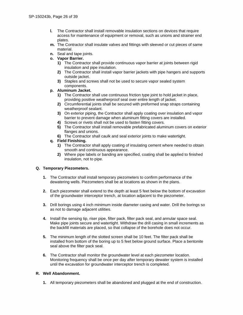
SP-150243b, Page 26 of 39
l. The Contractor shall install removable insulation sections on devices that require access for maintenance of equipment or removal, such as unions and strainer end plates.
m. The Contractor shall insulate valves and fittings with sleeved or cut pieces of same material.
n. Seal and tape joints. o. Vapor Barrier.
1) The Contractor shall provide continuous vapor barrier at joints between rigid insulation and pipe insulation.
2) The Contractor shall install vapor barrier jackets with pipe hangers and supports outside jacket.
3) Staples and screws shall not be used to secure vapor sealed system components.
p. Aluminum Jacket. 1) The Contractor shall use continuous friction type joint to hold jacket in place,
providing positive weatherproof seal over entire length of jacket. 2) Circumferential joints shall be secured with preformed snap straps containing
weatherproof sealant. 3) On exterior piping, the Contractor shall apply coating over insulation and vapor
barrier to prevent damage when aluminum fitting covers are installed. 4) Screws or rivets shall not be used to fasten fitting covers. 5) The Contractor shall install removable prefabricated aluminum covers on exterior
flanges and unions. 6) The Contractor shall caulk and seal exterior joints to make watertight.
q. Field Finishing. 1) The Contractor shall apply coating of insulating cement where needed to obtain
smooth and continuous appearance. 2) Where pipe labels or banding are specified, coating shall be applied to finished
insulation, not to pipe.
Q. Temporary Piezometers. 1. The Contractor shall install temporary piezometers to confirm performance of the
dewatering wells. Piezometers shall be at locations as shown in the plans.
2. Each piezometer shall extend to the depth at least 5 feet below the bottom of excavation of the groundwater interceptor trench, at location adjacent to the piezometer.
3. Drill borings using 4 inch minimum inside diameter casing and water. Drill the borings so as not to damage adjacent utilities.
4. Install the sensing tip, riser pipe, filter pack, filter pack seal, and annular space seal. Make pipe joints secure and watertight. Withdraw the drill casing in small increments as the backfill materials are placed, so that collapse of the borehole does not occur.
5. The minimum length of the slotted screen shall be 10 feet. The filter pack shall be installed from bottom of the boring up to 5 feet below ground surface. Place a bentonite seal above the filter pack seal.
6. The Contractor shall monitor the groundwater level at each piezometer location. Monitoring frequency shall be once per day after temporary dewater system is installed until the excavation for groundwater interceptor trench is completed.
R. Well Abandonment.
1. All temporary piezometers shall be abandoned and plugged at the end of construction.
SP-150243b, Page 27 of 39
2. Wells that are not converted to permanent groundwater monitoring well shall be abandoned and plugged at the end of construction.
3. Well plugging shall be performed in accordance with the Iowa Administrative Code (IAC), Environmental Protection Commission (567), Chapter 39.
S. Site Restoration.
1. The Contractor shall remove all temporary dewatering related equipment, vault boxes of
temporary piezometers and abandoned dewatering wells, well header piping, temporary header discharge pipe, valves and air release manholes and restore each location. It should be noted that it may not be possible to remove the temporary header discharge pipe sections crossing US-63, between temporary dewatering wells DW-1 and DW-22, and DW-13 and temporary dewatering discharge point at Virden Creek Enclosure near STA 82+00, and these pipe sections shall be plug and fill with CLSM for abandonment in accordance with requirements in Article, 2503.03, F of the Standard Specifications.
2. Valve boxes of the dewatering wells that are converted into permanent groundwater monitoring well shall remain in place.
3. The Contractor shall support the ground and protect existing structures and utilities
during removal of the temporary dewatering system.
4. The Contractor shall backfill all trenches with suitable Class II or Class III backfill material in accordance with Article 2552.02, C of the Standard Specifications. Backfill shall be placed in lifts not exceeding 6 inches. Compact backfill Class II backfill material in accordance to Article 2552.03, E.5.c and Class III backfill material in accordance to Article 2552.03, E.5.d of the Standard Specifications.
150243b.04 METHOD OF MEASUREMENT.
A. Temporary Dewatering Well Drilling in Soil.
Measurement for Temporary Dewatering Well Drilling in Soil will be by linear feet of drilling in soil.
B. Temporary Dewatering Well Drilling in Rock. Measurement for Temporary Dewatering Well Drilling in Rock will be by linear feet of drilling in rock.
C. Temporary Dewatering Well.
Each size of temporary dewatering well will be counted.
D. Air Release Valve Manhole. Each air release valve manhole will be counted.
E. Header Discharge Pipe.
Measurement for Header Discharge Pipe will be lump sum.
F. Electricity Wiring for Temporary Dewatering System. Measurement for Electricity Wiring for Temporary Dewatering System will be lump sum.
G. Temporary Dewatering Discharge Point. Each Temporary Dewatering Discharge Point will be counted.
H. Temporary Piezometer.
Each Temporary Piezometer will be counted.
SP-150243b, Page 28 of 39
I. Operation of Temporary Dewatering System. Measurement for Operation of Temporary Dewatering System will be lump sum.
150243b.05 BASIS OF PAYMENT.
A. Temporary Dewatering Well Drilling in Soil. 1. Payment for Temporary Dewatering Well Drilling in Soil will be at the contract unit price
per linear foot.
2. Payment is full compensation for perform drilling in soil and disposal of soil cuttings.
B. Temporary Dewatering Well Drilling in Rock. 1. Payment for Temporary Dewatering Well Drilling in Rock will be at the contract unit price
per linear foot.
2. Payment is full compensation for performing drilling in rock and disposal of cuttings.
C. Temporary Dewatering Well. 1. Payment will be at the contract unit price for each size of well.
2. Payment is full compensation for:
Furnishing and installing well screen assembly and well casing. Furnishing and placing well filter pack. Performing well development. Furnishing and placing well cement/grout seal. Furnishing, installing and removal of submersible pumps. Furnishing, installing and removal of well pump control panel and its concrete pad. Furnishing, installing and removal of dewatering well vault box and mechanical
assembly inside each vault box (including pipe support, service saddles, valves, heat tracing and insulation, and pipe fittings).
Furnishing, installing and removal of pipe penetrations through vault box. Furnishing, installing and removal of pipe between vault box and header discharge
pipe. Excavation, temporary support (as needed), backfill and fill for vault box and concrete
pad installation. Supplying the electricity to operate the temporary dewatering wells. Performing well abandonment and plugging, or conversion into permanent
groundwater monitoring well (as per the plans). Site restoration at the temporary dewatering wells and vault box locations.
D. Air Release Valve Manhole.
1. Payment will be at the contract unit price for each air release valve manhole.
2. Payment is full compensation for:
Excavation, temporary support (if needed), and backfill for air release valve manhole installation.
Furnishing, installing and removal of air release valve manhole. Furnishing, installing and removal of air release valve. Furnishing, installing and removal of pipe penetrations through manhole. Site restoration at the air release valve manhole locations.
SP-150243b, Page 29 of 39
E. Header Discharge Pipe.
1. Payment for Header Discharge Pipe will be at the contract unit price per lump sum.
2. Payment is full compensation for: Earthwork for working platform. Excavation, temporary shoring (if needed) and backfill for header discharge pipe
installation. Furnishing, installing and removal of header discharge pipe and associated fittings. Plugging and filling with CLSM for abandonment the temporary header discharge
pipe sections crossing US-63, between temporary dewatering wells DW-1 and DW-22, and DW-13 and temporary dewatering discharge point at Virden Creek Enclosure near STA 82+00.
Site restoration along the heading discharge pipe.
F. Electricity Wiring for Temporary Dewatering System. 1. Payment for Electrical Wiring for Temporary Dewatering System will be at the contract
unit price per lump sum.
2. Payment is full compensation for furnishing, installing and removal of conduits, conductors, and combination motor starter, utility meters and circuit breakers.
G. Temporary Dewatering Discharge Point.
1. Payment will be at the contract unit price for each pipe penetration through discharge
point at Virden Creek Culvert.
2. Payment is full compensation for: Excavation and backfill associated with pipe penetration work Furnishing and installing pipe penetration through Virden Creek Enclosure Furnishing and installing Tideflex inline check valve
H. Temporary Piezometer.
1. Payment will be at the contract unit price for each temporary piezometer.
2. Payment is full compensation for Installing, monitoring, and abandonment of temporary
piezometers.
I. Operation of Temporary Dewatering System. 1. Payment will be at the contract unit price per lump sum.
2. Payment is full compensation for:
Supplying the electricity to operate the temporary dewatering system. Operating the temporary dewatering system for the period as per the plans.
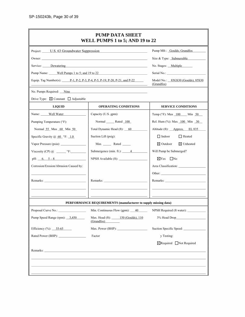
SP-150243b, Page 30 of 39
PUMP DATA SHEET WELL PUMPS 1 to 5; AND 19 to 22
Project: U.S. 63 Groundwater Suppression Pump Mfr.: Goulds; Grundfos
Owner: Size & Type: Submersible
Service: Dewatering No. Stages: Multiple
Pump Name: Well Pumps 1 to 5; and 19 to 22 Serial No.:
Equip. Tag Number(s): P-1, P-2, P-3, P-4, P-5, P-19, P-20, P-21, and P-22
Model No.: 85GS30 (Goulds), 85S30 (Grundfos)
No. Pumps Required: Nine
Drive Type: Constant Adjustable
LIQUID OPERATING CONDITIONS SERVICE CONDITIONS
Name: Well Water Capacity (U.S. gpm): Temp (F): Max 100 Min 50
Pumping Temperature (F): Normal Rated 100 Rel. Hum (%): Max 100 Min 30
Normal 55 Max 60 Min 50 Total Dynamic Head (ft): 60 Altitude (ft): Approx. EL 835
Specific Gravity @ 60 F: 1.0 Suction Lift (psig): Indoor Heated
Vapor Pressure (psia): Max Rated Outdoor Unheated
Viscosity (CP) @ F: Submergence (min. ft.): 4 Will Pump be Submerged?
pH: 6. 5 – 8 NPSH Available (ft): Yes No
Corrosion/Erosion/Abrasion Caused by: Area Classification:
Other:
Remarks: Remarks: Remarks:
PERFORMANCE REQUIREMENTS (manufacturer to supply missing data)
Proposal Curve No.: Min. Continuous Flow (gpm): 40 NPSH Required (ft water):
Pump Speed Range (rpm): 3,450 Max. Head (ft): 150 (Goulds), 110 (Grundfos)
3% Head Drop
Efficiency (%): 55-65 Max. Power (BHP): Suction Specific Speed:
Rated Power (BHP): Factor y Testing:
Required Not Required
Remarks:
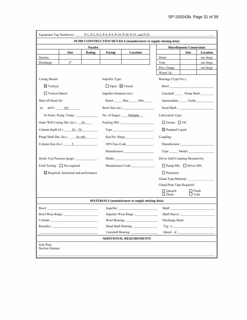
SP-150243b, Page 31 of 39
Equipment Tag Number(s): P-1, P-2, P-3, P-4, P-5, P-19, P-20, P-21, and P-22
PUMP CONSTRUCTION DETAILS (manufacturer to supply missing data)
Nozzles Miscellaneous Connections
Size Rating Facing Location Size Location
Suction - Drain see dwgs Discharge 2" Vent see dwgs Pres. Gauge see dwgs Warm Up
Casing Mount: Impeller Type: Bearings (Type/No.):
Vertical Open Closed Bowl
Vertical Barrel Impeller Diameter (in.): Lineshaft Pump Shaft
Shut-off Head (ft): Rated Max Min Intermediate Guide
At 60F: 185 Bowl Size (in.) Head Shaft:
At Norm. Pump. Temp.: No. of Stages: Multiple Lubrication Type:
Outer Well Casing Dia. (in.): 10 Packing Mfr: Grease Oil
Column depth (ft.) 26 – 36 Type Pumped Liquid
Pump Shaft Dia. (In.): by mfr. Size/No. Rings Coupling:
Column Size (In.): 3 API Class Code Manufacturer
Manufacturer Type Model
Hydro Test Pressure (psig): Model Driver Half-Coupling Mounted by:
Field Testing: Not required Manufacturer Code Pump Mfr. Driver Mfr.
Required, functional and performance Purchaser
Gland Type/Material:
Gland Plate Taps Required:
Quench Flush Drain Vent
MATERIALS (manufacturer to supply missing data)
Bowl: Impeller: Shaft:
Bowl Wear Rings: Impeller Wear Rings: Shaft Sleeve:
Column: Bowl Bearing: Discharge Head:
Remarks: Head Shaft Bearing: Typ e
Lineshaft Bearing: Materi al
ADDITIONAL REQUIREMENTS
Sole Plate Suction Strainer
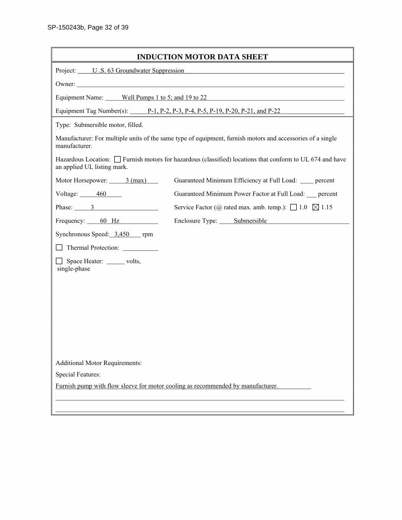
SP-150243b, Page 32 of 39
INDUCTION MOTOR DATA SHEET
Project: U .S. 63 Groundwater Suppression
Owner:
Equipment Name: Well Pumps 1 to 5; and 19 to 22
Equipment Tag Number(s): P-1, P-2, P-3, P-4, P-5, P-19, P-20, P-21, and P-22
Type: Submersible motor, filled.
Manufacturer: For multiple units of the same type of equipment, furnish motors and accessories of a single manufacturer.
Hazardous Location: Furnish motors for hazardous (classified) locations that conform to UL 674 and have an applied UL listing mark.
Motor Horsepower: 3 (max) Guaranteed Minimum Efficiency at Full Load: percent
Voltage: 460 Guaranteed Minimum Power Factor at Full Load: ___ percent
Phase: 3 Service Factor (@ rated max. amb. temp.): 1.0 1.15
Frequency: 60 Hz Enclosure Type: Submersible
Synchronous Speed: 3,450 rpm
Thermal Protection:
Space Heater: volts, single-phase
Additional Motor Requirements:
Special Features:
Furnish pump with flow sleeve for motor cooling as recommended by manufacturer.
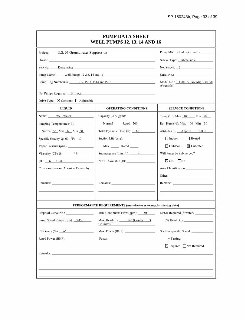
SP-150243b, Page 33 of 39
PUMP DATA SHEET WELL PUMPS 12, 13, 14 AND 16
Project: U.S. 63 Groundwater Suppression Pump Mfr.: Goulds, Grundfos
Owner: Size & Type: Submersible
Service: Dewatering No. Stages: 2
Pump Name: Well Pumps 12 ,13, 14 and 16 Serial No.:
Equip. Tag Number(s): P-12, P-13, P-14 and P-16 Model No.: 160L05 (Goulds), 230S50 (Grundfos)
No. Pumps Required: F our
Drive Type: Constant Adjustable
LIQUID OPERATING CONDITIONS SERVICE CONDITIONS
Name: Well Water Capacity (U.S. gpm): Temp (F): Max 100 Min 50
Pumping Temperature (F): Normal Rated 200 Rel. Hum (%): Max 100 Min 30
Normal 55 Max 60 Min 50 Total Dynamic Head (ft): 60 Altitude (ft): Approx. EL 835
Specific Gravity @ 60 F: 1.0 Suction Lift (psig): Indoor Heated
Vapor Pressure (psia): Max Rated Outdoor Unheated
Viscosity (CP) @ F: Submergence (min. ft.): 4 Will Pump be Submerged?
pH: 6. 5 – 8 NPSH Available (ft): Yes No
Corrosion/Erosion/Abrasion Caused by: Area Classification:
Other:
Remarks: Remarks: Remarks:
PERFORMANCE REQUIREMENTS (manufacturer to supply missing data)
Proposal Curve No.: Min. Continuous Flow (gpm): 50 NPSH Required (ft water):
Pump Speed Range (rpm): 3,450 Max. Head (ft): 145 (Goulds), 103 Grundfos
3% Head Drop
Efficiency (%): 65 Max. Power (BHP): Suction Specific Speed:
Rated Power (BHP): Factor y Testing:
Required Not Required
Remarks:
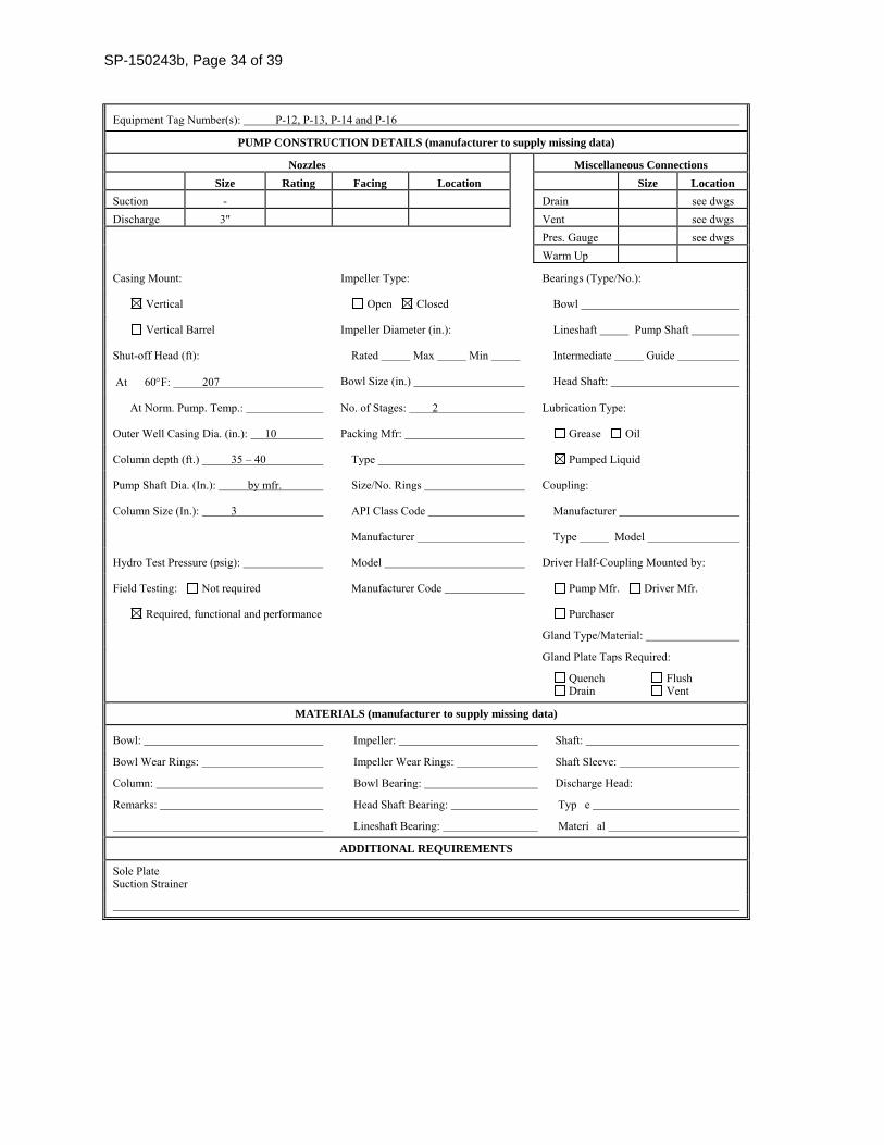
SP-150243b, Page 34 of 39
Equipment Tag Number(s): P-12, P-13, P-14 and P-16
PUMP CONSTRUCTION DETAILS (manufacturer to supply missing data)
Nozzles Miscellaneous Connections
Size Rating Facing Location Size Location
Suction - Drain see dwgs Discharge 3" Vent see dwgs Pres. Gauge see dwgs Warm Up
Casing Mount: Impeller Type: Bearings (Type/No.):
Vertical Open Closed Bowl
Vertical Barrel Impeller Diameter (in.): Lineshaft Pump Shaft
Shut-off Head (ft): Rated Max Min Intermediate Guide
At 60F: 207 Bowl Size (in.) Head Shaft:
At Norm. Pump. Temp.: No. of Stages: 2 Lubrication Type:
Outer Well Casing Dia. (in.): 10 Packing Mfr: Grease Oil
Column depth (ft.) 35 – 40 Type Pumped Liquid
Pump Shaft Dia. (In.): by mfr. Size/No. Rings Coupling:
Column Size (In.): 3 API Class Code Manufacturer
Manufacturer Type Model
Hydro Test Pressure (psig): Model Driver Half-Coupling Mounted by:
Field Testing: Not required Manufacturer Code Pump Mfr. Driver Mfr.
Required, functional and performance Purchaser
Gland Type/Material:
Gland Plate Taps Required:
Quench Flush Drain Vent
MATERIALS (manufacturer to supply missing data)
Bowl: Impeller: Shaft:
Bowl Wear Rings: Impeller Wear Rings: Shaft Sleeve:
Column: Bowl Bearing: Discharge Head:
Remarks: Head Shaft Bearing: Typ e
Lineshaft Bearing: Materi al
ADDITIONAL REQUIREMENTS
Sole Plate Suction Strainer
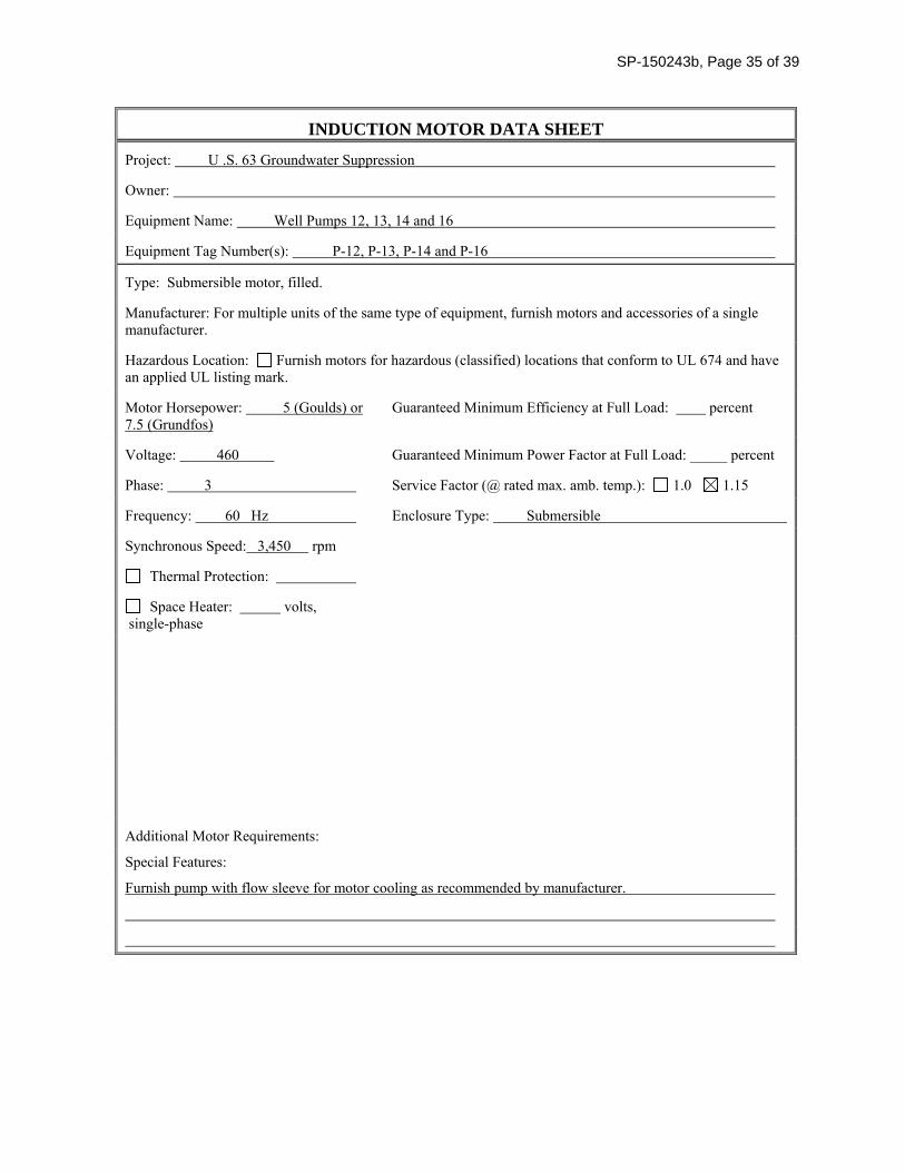
SP-150243b, Page 35 of 39
INDUCTION MOTOR DATA SHEET
Project: U .S. 63 Groundwater Suppression
Owner:
Equipment Name: Well Pumps 12, 13, 14 and 16
Equipment Tag Number(s): P-12, P-13, P-14 and P-16
Type: Submersible motor, filled.
Manufacturer: For multiple units of the same type of equipment, furnish motors and accessories of a single manufacturer.
Hazardous Location: Furnish motors for hazardous (classified) locations that conform to UL 674 and have an applied UL listing mark.
Motor Horsepower: 5 (Goulds) or 7.5 (Grundfos)
Guaranteed Minimum Efficiency at Full Load: percent
Voltage: 460 Guaranteed Minimum Power Factor at Full Load: _____ percent
Phase: 3 Service Factor (@ rated max. amb. temp.): 1.0 1.15
Frequency: 60 Hz Enclosure Type: Submersible
Synchronous Speed: 3,450 rpm
Thermal Protection:
Space Heater: volts, single-phase
Additional Motor Requirements:
Special Features:
Furnish pump with flow sleeve for motor cooling as recommended by manufacturer.
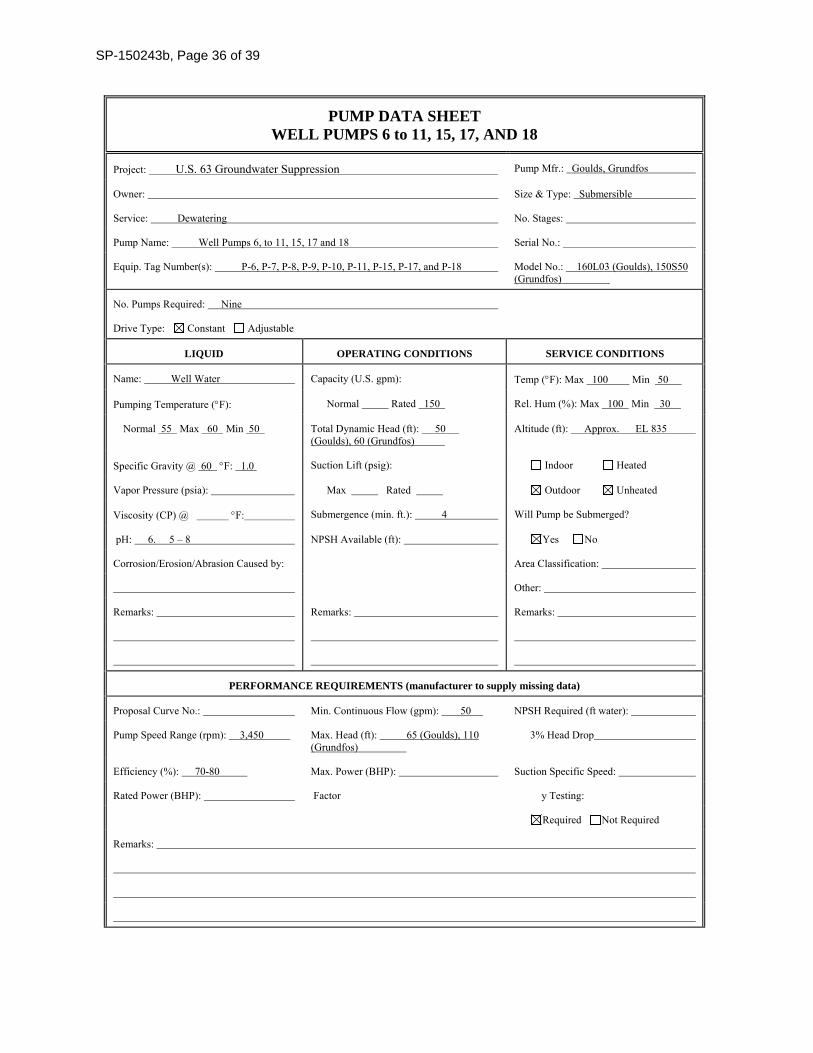
SP-150243b, Page 36 of 39
PUMP DATA SHEET WELL PUMPS 6 to 11, 15, 17, AND 18
Project: U.S. 63 Groundwater Suppression Pump Mfr.: Goulds, Grundfos
Owner: Size & Type: Submersible
Service: Dewatering No. Stages:
Pump Name: Well Pumps 6, to 11, 15, 17 and 18 Serial No.:
Equip. Tag Number(s): P-6, P-7, P-8, P-9, P-10, P-11, P-15, P-17, and P-18 Model No.: 160L03 (Goulds), 150S50 (Grundfos)
No. Pumps Required: Nine
Drive Type: Constant Adjustable
LIQUID OPERATING CONDITIONS SERVICE CONDITIONS
Name: Well Water Capacity (U.S. gpm): Temp (F): Max 100 Min 50
Pumping Temperature (F): Normal Rated 150 Rel. Hum (%): Max 100 Min 30
Normal 55 Max 60 Min 50 Total Dynamic Head (ft): 50 (Goulds), 60 (Grundfos)
Altitude (ft): Approx. EL 835
Specific Gravity @ 60 F: 1.0 Suction Lift (psig): Indoor Heated
Vapor Pressure (psia): Max Rated Outdoor Unheated
Viscosity (CP) @ F: Submergence (min. ft.): 4 Will Pump be Submerged?
pH: 6. 5 – 8 NPSH Available (ft): Yes No
Corrosion/Erosion/Abrasion Caused by: Area Classification:
Other:
Remarks: Remarks: Remarks:
PERFORMANCE REQUIREMENTS (manufacturer to supply missing data)
Proposal Curve No.: Min. Continuous Flow (gpm): 50 NPSH Required (ft water):
Pump Speed Range (rpm): 3,450 Max. Head (ft): 65 (Goulds), 110 (Grundfos)
3% Head Drop
Efficiency (%): 70-80 Max. Power (BHP): Suction Specific Speed:
Rated Power (BHP): Factor y Testing:
Required Not Required
Remarks:
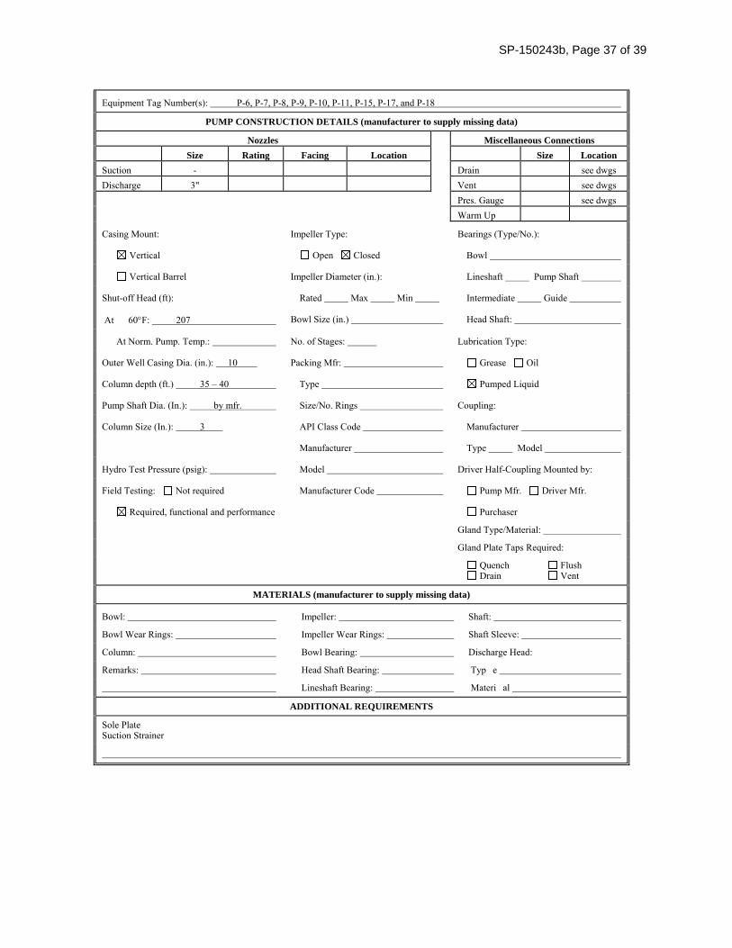
SP-150243b, Page 37 of 39
Equipment Tag Number(s): P-6, P-7, P-8, P-9, P-10, P-11, P-15, P-17, and P-18
PUMP CONSTRUCTION DETAILS (manufacturer to supply missing data)
Nozzles Miscellaneous Connections
Size Rating Facing Location Size Location
Suction - Drain see dwgs Discharge 3" Vent see dwgs Pres. Gauge see dwgs Warm Up
Casing Mount: Impeller Type: Bearings (Type/No.):
Vertical Open Closed Bowl
Vertical Barrel Impeller Diameter (in.): Lineshaft Pump Shaft
Shut-off Head (ft): Rated Max Min Intermediate Guide
At 60F: 207 Bowl Size (in.) Head Shaft:
At Norm. Pump. Temp.: No. of Stages: Lubrication Type:
Outer Well Casing Dia. (in.): 10 Packing Mfr: Grease Oil
Column depth (ft.) 35 – 40 Type Pumped Liquid
Pump Shaft Dia. (In.): by mfr. Size/No. Rings Coupling:
Column Size (In.): 3 API Class Code Manufacturer
Manufacturer Type Model
Hydro Test Pressure (psig): Model Driver Half-Coupling Mounted by:
Field Testing: Not required Manufacturer Code Pump Mfr. Driver Mfr.
Required, functional and performance Purchaser
Gland Type/Material:
Gland Plate Taps Required:
Quench Flush Drain Vent
MATERIALS (manufacturer to supply missing data)
Bowl: Impeller: Shaft:
Bowl Wear Rings: Impeller Wear Rings: Shaft Sleeve:
Column: Bowl Bearing: Discharge Head:
Remarks: Head Shaft Bearing: Typ e
Lineshaft Bearing: Materi al
ADDITIONAL REQUIREMENTS
Sole Plate Suction Strainer
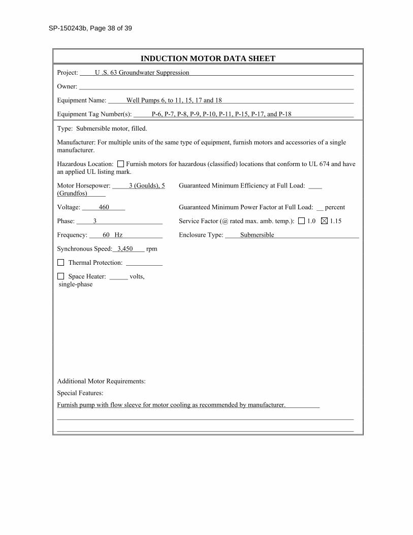
SP-150243b, Page 38 of 39
INDUCTION MOTOR DATA SHEET
Project: U .S. 63 Groundwater Suppression
Owner:
Equipment Name: Well Pumps 6, to 11, 15, 17 and 18
Equipment Tag Number(s): P-6, P-7, P-8, P-9, P-10, P-11, P-15, P-17, and P-18
Type: Submersible motor, filled.
Manufacturer: For multiple units of the same type of equipment, furnish motors and accessories of a single manufacturer.
Hazardous Location: Furnish motors for hazardous (classified) locations that conform to UL 674 and have an applied UL listing mark.
Motor Horsepower: 3 (Goulds), 5 (Grundfos)
Guaranteed Minimum Efficiency at Full Load:
Voltage: 460 Guaranteed Minimum Power Factor at Full Load: __ percent
Phase: 3 Service Factor (@ rated max. amb. temp.): 1.0 1.15
Frequency: 60 Hz Enclosure Type: Submersible
Synchronous Speed: 3,450 rpm
Thermal Protection:
Space Heater: volts, single-phase
Additional Motor Requirements:
Special Features:
Furnish pump with flow sleeve for motor cooling as recommended by manufacturer.
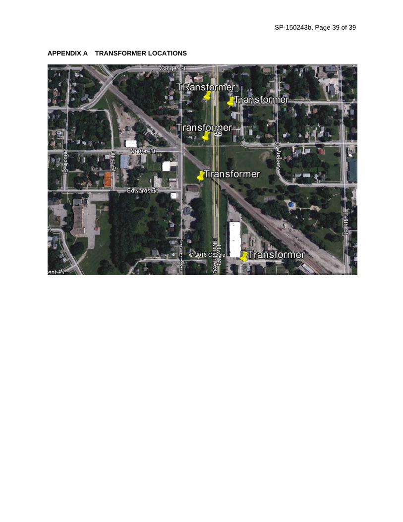
SP-150243b, Page 39 of 39
APPENDIX A TRANSFORMER LOCATIONS
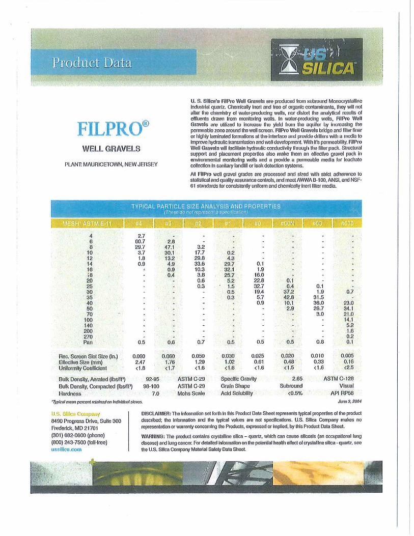
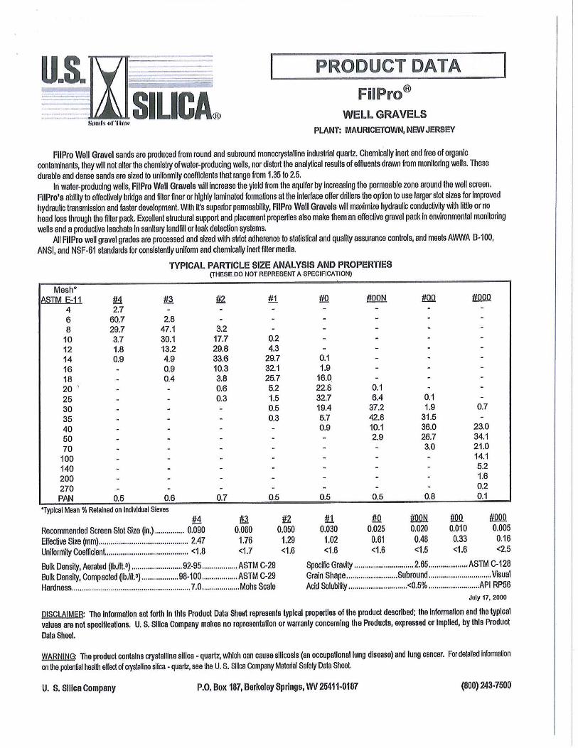
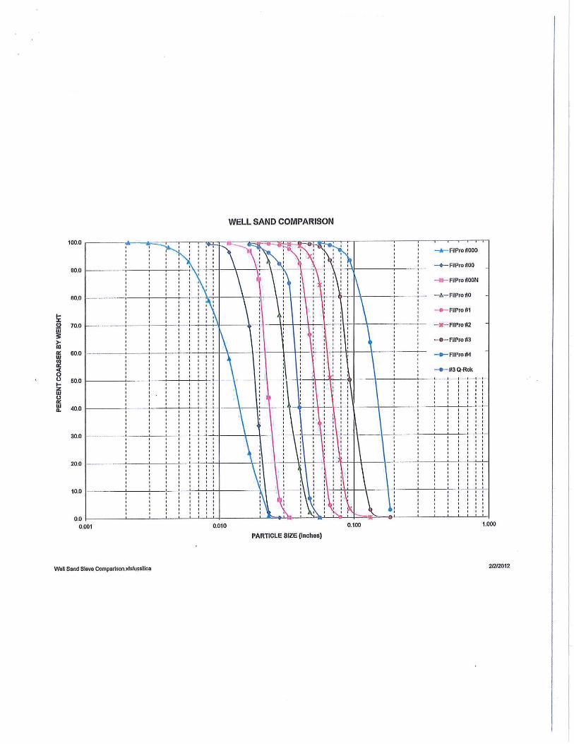
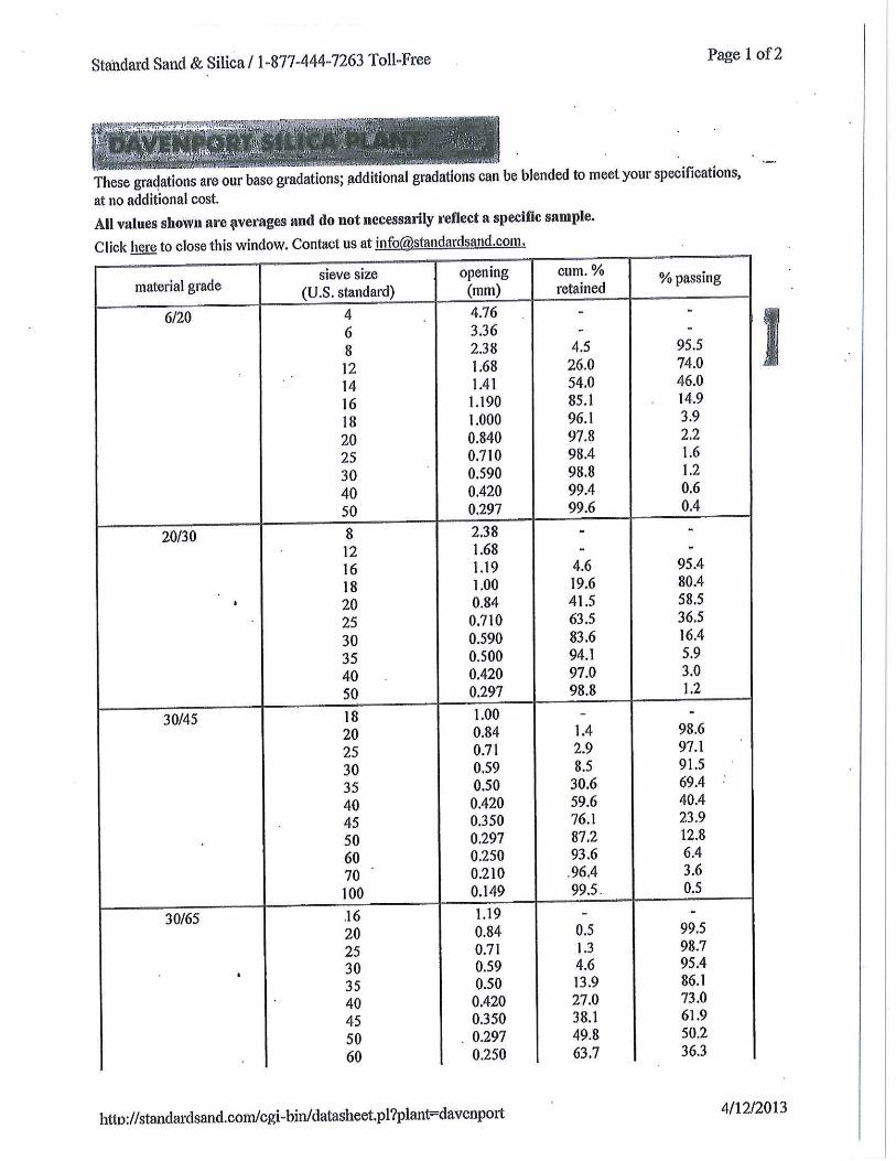
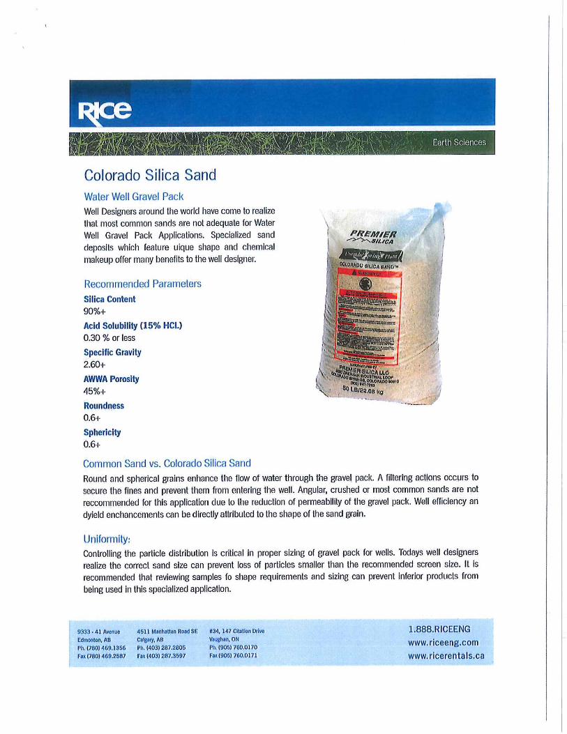
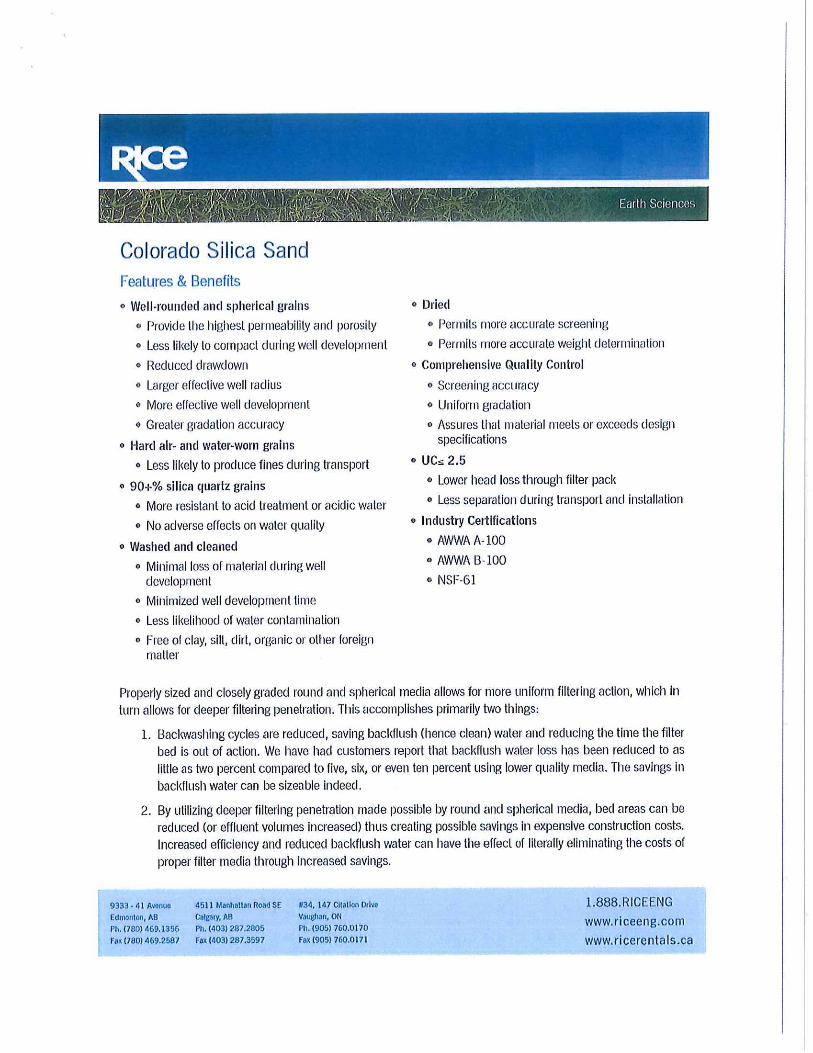
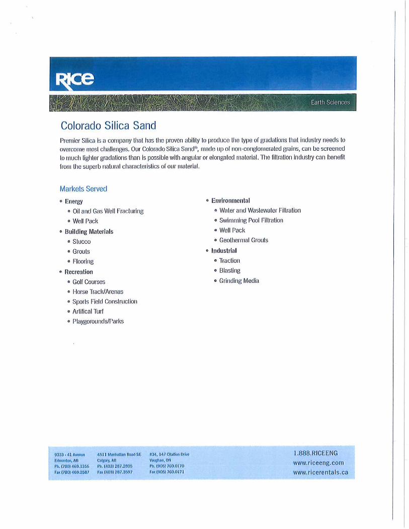
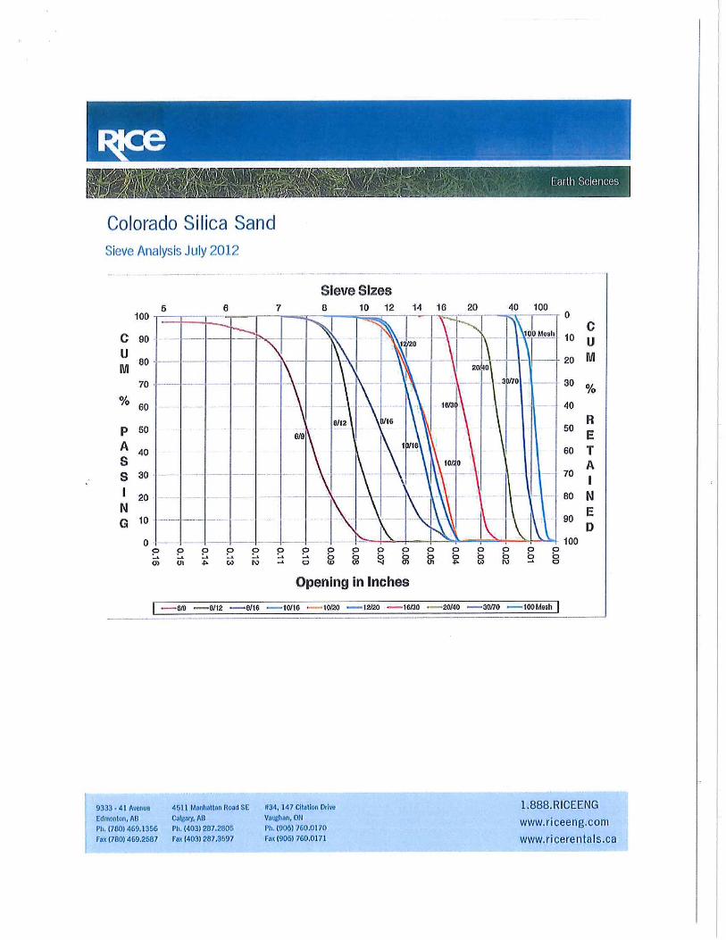
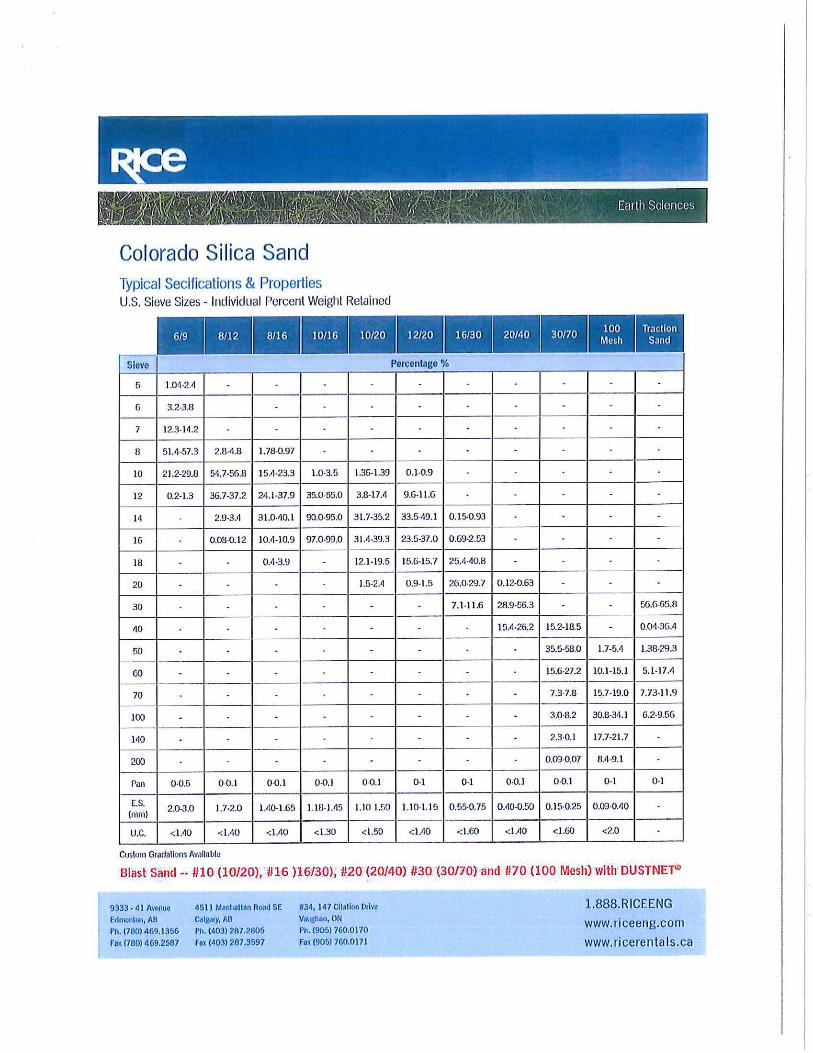
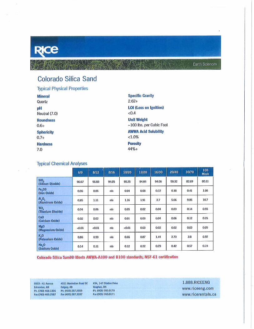
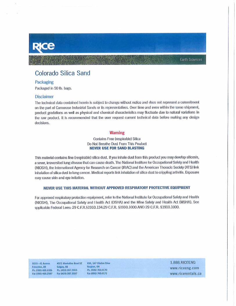
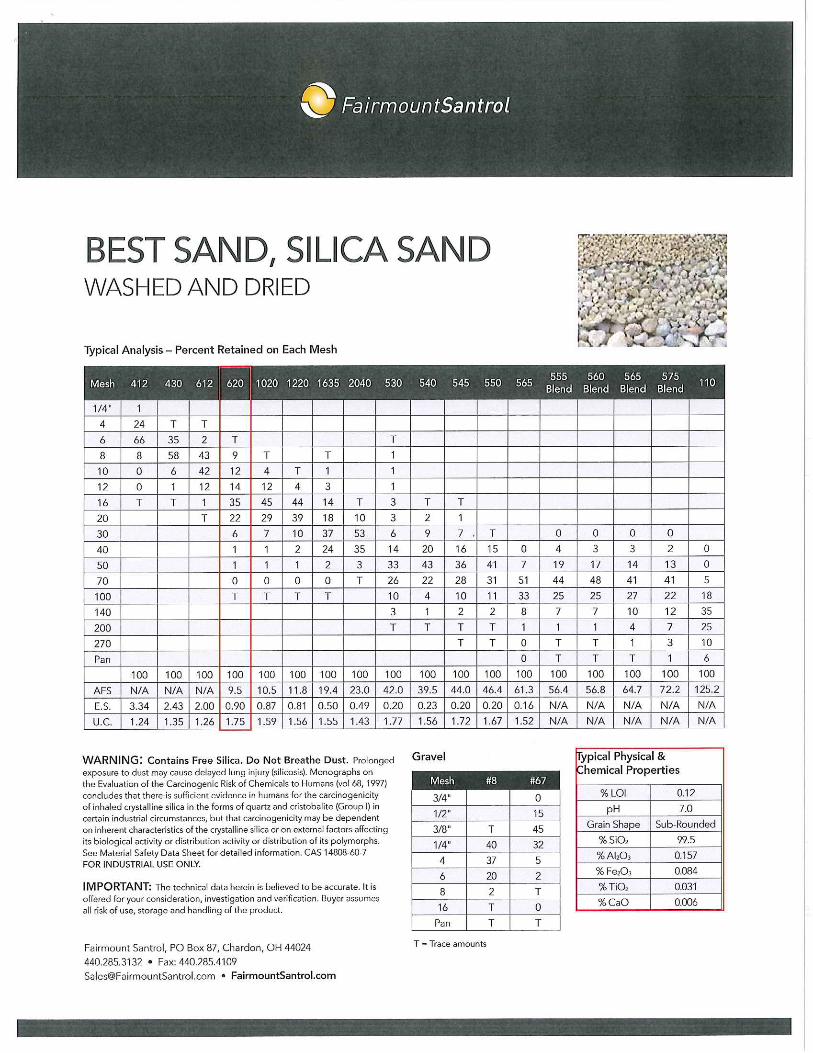
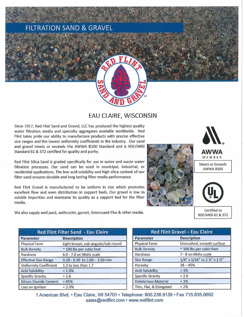
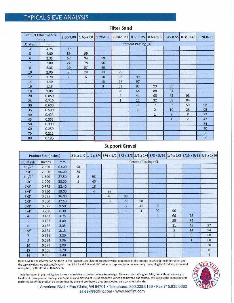
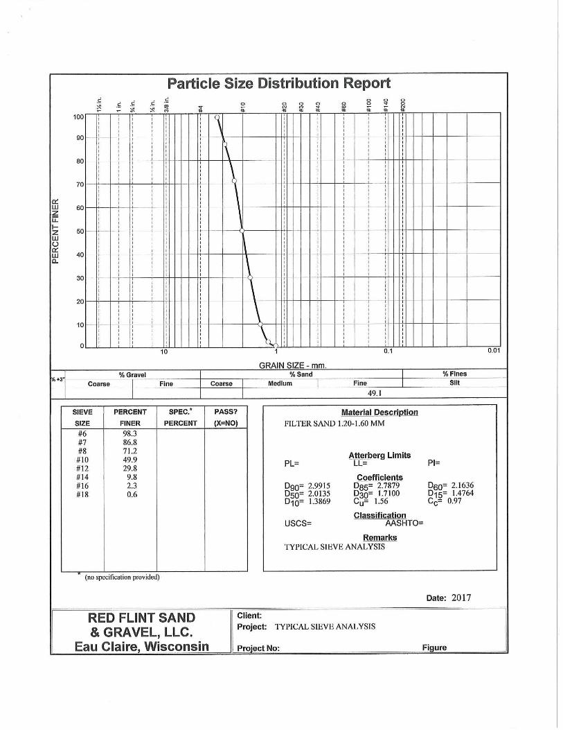
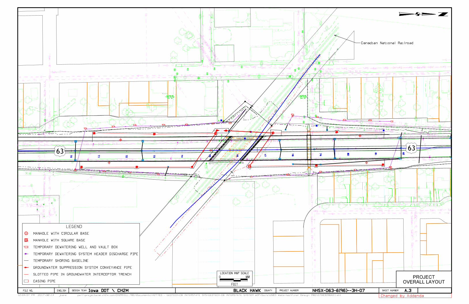
jkane12:04:37 PM pw:\\projectwise.ch2m.com:CH2MHILL_TBG\Documents\427763 - GEOTECH-CB INTERSTATE SYS\GEOTECH-CB INTERSTATE SYSTEM WIP\Soils\US63 Waterloo\Final Design (96)\07063096A01.sht
DESIGN TEAM PROJECT NUMBER SHEET NUMBER COUNTY
2017\06\14
ENGLISHFILE NO.
TP
TP
VIRDEN CREEK ENCLOSURE
San.
San. 8"
8"
San. San.San.
San.
24"24"24"24" San.
30"
24"
10"
10"
8"
San.
San.
San.
San.
24"
San. 8"
15"
San.
24"
San.
San.
San.
San.
San.
San.
8"
10"
12"
12"
12"
12"
8"
W
WW
WW
W6"
6"
6"6"
6"
W6"W6"
G
G
GG
G
G
2"
4"
4"
4"4" 4"
4" G
G
GG
1‚"
1‚"
8"Tile
15"Tile15"Tile15"Tile
12"Tile12"Tile
15"Tile15"Tile
15"Tile
8"Tile8"Tile 15"Tile 8"Tile 8"Tile8"Tile
VIRDEN CREEK ENCLOSURE
VIR
DEN CREEK ENCLOSURE
St
St
St
15"St
42"St
42"St (A
bandoned)
VIR
DEN CREEK ENCLOSURE
WW
W W W W
W W W
WW6" 6"W
15054822.82
UTILITY ELEVATIONBOTTOM BASIN
15075823.41
UTILITY ELEVATIONBOTTOM BASIN
15080824.88
UTILITY ELEVATIONBOTTOM BASIN
15052829.17
CONCRETE OR A/C SLABNE COR CONC CUL TOP
15053829.20
CONCRETE OR A/C SLABSE COR CONC CUL TOP
15055829.63
PROFILE SHOTTOP CULVERT HEADED TO PUMP HOUSE
15056829.70
PROFILE SHOTTOP CULVERT HEADED TO PUMP HOUSE
600832.54
BRIDGE SWC SW WING(DIST. 2 JAN 9_17 SURVEY)
602832.58
BRIDGE SWC SE WING(DIST. 2 JAN 9_17 SURVEY)
605832.58
BRIDGE NWC NE WING(DIST. 2 JAN 9_17 SURVEY)
607832.59
BRIDGE NEC NW WING(DIST. 2 JAN 9_17 SURVEY)
601832.59
BRIDGE SEC SW WING(DIST. 2 JAN 9_17 SURVEY)
603832.63
BRIDGE SEC SE WING(DIST. 2 JAN 9_17 SURVEY)
606832.81
BRIDGE NWC NW WING(DIST. 2 JAN 9_17 SURVEY)
604832.85
BRIDGE NEC NE WING(DIST. 2 JAN 9_17 SURVEY)
837.71
837.72
837.72
837.73
837.73
837.74
837.75
837.75
837.75
837.75
837.76
837.76
837.76
841.95
841.96
842.02
842.09 842.09
842.64
843.20
843.20
843.24
843.28
843.57
843.59 843.61
843.61
843.63
843.63
843.64
843.65843.66
843.66
843.67
843.68
843.68
843.69
843.69
843.72843.72
843.80
843.98
844.04
844.06
844.15
844.18
844.23
844.28
844.33
844.36
844.45
844.81
844.93
844.93
844.95
844.95
PIPE CULVERT
844.96
845.05
845.28
PIPE CULVERT
845.53 845.55
845.93
846.74847.08
847.15
15006847.23
CULVERTEAST EDGE VIRDEN CREEK CUL
847.37
847.54
15005847.58
CULVERTEAST EDGE VIRDEN CREEK CUL
847.61
847.65847.66
847.71 847.72
15004847.80
CULVERTEAST EDGE VIRDEN CREEK CUL
847.85
847.87
847.87
847.88
847.94
847.95
847.97
848.02
15003848.07
CULVERTEAST EDGE VIRDEN CREEK CUL
848.08
848.15
15002848.40
CULVERTEAST EDGE VIRDEN CREEK BOX CULV
15001848.75
CULVERTEAST EDGE VIRDEN CREEK BOX CUL
851.00
851.07
851.17
15050851.52
BUILDING OR FOUNDATIONNE COR BUILD FOOTING
15051851.63
BUILDING OR FOUNDATIONSE COR BUILD FOOTING
Sec. 23
T-89N R-13W
WATERLOO
Sec. 23
T-89N R-13W
WATERLOO
70
75
80
81
8279
78
77
7671
72
73
74
Iowa DOT \ CH2M BLACK HAWK NHSX-063-6(96)--3H-07
100
FEET
O
LOCATION MAP SCALE
A.3
OVERALL LAYOUT
PROJECT
Canadian National Railroad
LEGEND
TEMPORARY SHORING BASELINE
MANHOLE WITH CIRCULAR BASE
MANHOLE WITH SQUARE BASE
TEMPORARY DEWATERING SYSTEM HEADER DISCHARGE PIPE
GROUNDWATER SUPPRESSION SYSTEM CONVEYANCE PIPE
SLOTTED PIPE IN GROUNDWATER INTERCEPTOR TRENCH
CASING PIPE
TEMPORARY DEWATERING WELL AND VAULT BOX
Changed by Addenda
6363
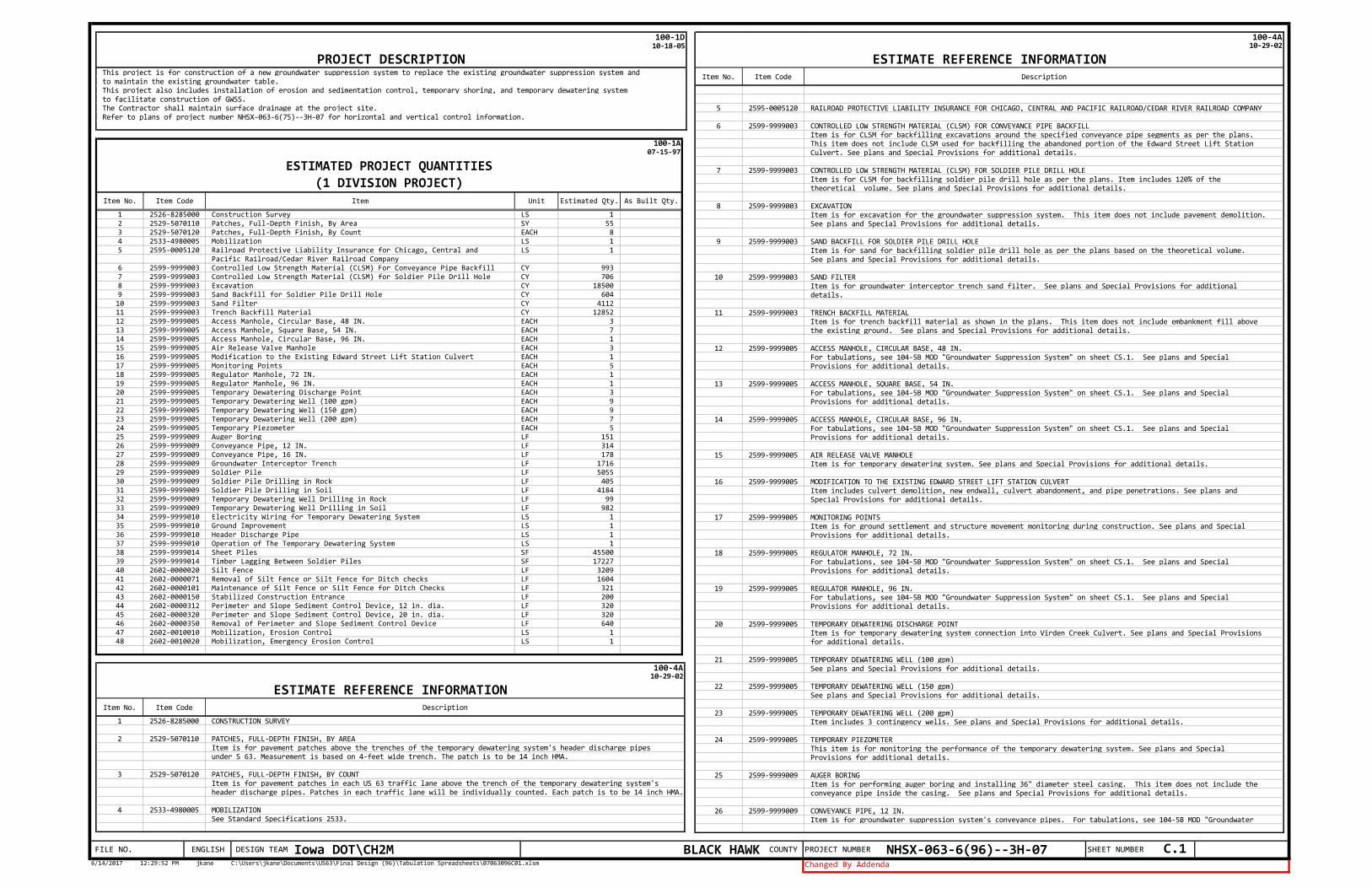
COUNTY PROJECT NUMBER NHSX-063-6(96)--3H-07 SHEET NUMBER C.1FILE NO. ENGLISH DESIGN TEAM Iowa DOT\CH2M BLACK HAWK6/14/2017 12:29:52 PM jkane C:\Users\jkane\Documents\US63\Final Design (96)\Tabulation Spreadsheets\07063096C01.xlsm Changed By Addenda
100-1D10-18-05
This project is for construction of a new groundwater suppression system to replace the existing groundwater suppression system andto maintain the existing groundwater table.This project also includes installation of erosion and sedimentation control, temporary shoring, and temporary dewatering systemto facilitate construction of GWSS.The Contractor shall maintain surface drainage at the project site.Refer to plans of project number NHSX-063-6(75)--3H-07 for horizontal and vertical control information.
PROJECT DESCRIPTION
1 2526-8285000 Construction Survey LS 12 2529-5070110 Patches, Full-Depth Finish, By Area SY 553 2529-5070120 Patches, Full-Depth Finish, By Count EACH 84 2533-4980005 Mobilization LS 15 2595-0005120 Railroad Protective Liability Insurance for Chicago, Central and LS 1
Pacific Railroad/Cedar River Railroad Company6 2599-9999003 Controlled Low Strength Material (CLSM) For Conveyance Pipe Backfill CY 9937 2599-9999003 Controlled Low Strength Material (CLSM) for Soldier Pile Drill Hole CY 7068 2599-9999003 Excavation CY 185009 2599-9999003 Sand Backfill for Soldier Pile Drill Hole CY 60410 2599-9999003 Sand Filter CY 411211 2599-9999003 Trench Backfill Material CY 1285212 2599-9999005 Access Manhole, Circular Base, 48 IN. EACH 313 2599-9999005 Access Manhole, Square Base, 54 IN. EACH 714 2599-9999005 Access Manhole, Circular Base, 96 IN. EACH 115 2599-9999005 Air Release Valve Manhole EACH 316 2599-9999005 Modification to the Existing Edward Street Lift Station Culvert EACH 117 2599-9999005 Monitoring Points EACH 518 2599-9999005 Regulator Manhole, 72 IN. EACH 119 2599-9999005 Regulator Manhole, 96 IN. EACH 120 2599-9999005 Temporary Dewatering Discharge Point EACH 321 2599-9999005 Temporary Dewatering Well (100 gpm) EACH 922 2599-9999005 Temporary Dewatering Well (150 gpm) EACH 923 2599-9999005 Temporary Dewatering Well (200 gpm) EACH 724 2599-9999005 Temporary Piezometer EACH 525 2599-9999009 Auger Boring LF 15126 2599-9999009 Conveyance Pipe, 12 IN. LF 31427 2599-9999009 Conveyance Pipe, 16 IN. LF 17828 2599-9999009 Groundwater Interceptor Trench LF 171629 2599-9999009 Soldier Pile LF 505530 2599-9999009 Soldier Pile Drilling in Rock LF 40531 2599-9999009 Soldier Pile Drilling in Soil LF 418432 2599-9999009 Temporary Dewatering Well Drilling in Rock LF 9933 2599-9999009 Temporary Dewatering Well Drilling in Soil LF 98234 2599-9999010 Electricity Wiring for Temporary Dewatering System LS 135 2599-9999010 Ground Improvement LS 136 2599-9999010 Header Discharge Pipe LS 137 2599-9999010 Operation of The Temporary Dewatering System LS 138 2599-9999014 Sheet Piles SF 4550039 2599-9999014 Timber Lagging Between Soldier Piles SF 1722740 2602-0000020 Silt Fence LF 320941 2602-0000071 Removal of Silt Fence or Silt Fence for Ditch checks LF 160442 2602-0000101 Maintenance of Silt Fence or Silt Fence for Ditch Checks LF 32143 2602-0000150 Stabilized Construction Entrance LF 20044 2602-0000312 Perimeter and Slope Sediment Control Device, 12 in. dia. LF 32045 2602-0000320 Perimeter and Slope Sediment Control Device, 20 in. dia. LF 32046 2602-0000350 Removal of Perimeter and Slope Sediment Control Device LF 64047 2602-0010010 Mobilization, Erosion Control LS 148 2602-0010020 Mobilization, Emergency Erosion Control LS 1
100-1A07-15-97
ESTIMATED PROJECT QUANTITIES(1 DIVISION PROJECT)
Item No. Item Code Item Unit Estimated Qty. As Built Qty.
1 2526-8285000 CONSTRUCTION SURVEY
2 2529-5070110 PATCHES, FULL-DEPTH FINISH, BY AREAItem is for pavement patches above the trenches of the temporary dewatering system's header discharge pipesunder S 63. Measurement is based on 4-feet wide trench. The patch is to be 14 inch HMA.
3 2529-5070120 PATCHES, FULL-DEPTH FINISH, BY COUNT Item is for pavement patches in each US 63 traffic lane above the trench of the temporary dewatering system's header discharge pipes. Patches in each traffic lane will be individually counted. Each patch is to be 14 inch HMA.
4 2533-4980005 MOBILIZATIONSee Standard Specifications 2533.
100-4A10-29-02
ESTIMATE REFERENCE INFORMATIONItem No. Item Code Description
5 2595-0005120 RAILROAD PROTECTIVE LIABILITY INSURANCE FOR CHICAGO, CENTRAL AND PACIFIC RAILROAD/CEDAR RIVER RAILROAD COMPANY
6 2599-9999003 CONTROLLED LOW STRENGTH MATERIAL (CLSM) FOR CONVEYANCE PIPE BACKFILLItem is for CLSM for backfilling excavations around the specified conveyance pipe segments as per the plans.This item does not include CLSM used for backfilling the abandoned portion of the Edward Street Lift StationCulvert. See plans and Special Provisions for additional details.
7 2599-9999003 CONTROLLED LOW STRENGTH MATERIAL (CLSM) FOR SOLDIER PILE DRILL HOLEItem is for CLSM for backfilling soldier pile drill hole as per the plans. Item includes 120% of the theoretical volume. See plans and Special Provisions for additional details.
8 2599-9999003 EXCAVATIONItem is for excavation for the groundwater suppression system. This item does not include pavement demolition.See plans and Special Provisions for additional details.
9 2599-9999003 SAND BACKFILL FOR SOLDIER PILE DRILL HOLEItem is for sand for backfilling soldier pile drill hole as per the plans based on the theoretical volume. See plans and Special Provisions for additional details.
10 2599-9999003 SAND FILTERItem is for groundwater interceptor trench sand filter. See plans and Special Provisions for additionaldetails.
11 2599-9999003 TRENCH BACKFILL MATERIALItem is for trench backfill material as shown in the plans. This item does not include embankment fill abovethe existing ground. See plans and Special Provisions for additional details.
12 2599-9999005 ACCESS MANHOLE, CIRCULAR BASE, 48 IN.For tabulations, see 104-5B MOD "Groundwater Suppression System" on sheet CS.1. See plans and SpecialProvisions for additional details.
13 2599-9999005 ACCESS MANHOLE, SQUARE BASE, 54 IN.For tabulations, see 104-5B MOD "Groundwater Suppression System" on sheet CS.1. See plans and SpecialProvisions for additional details.
14 2599-9999005 ACCESS MANHOLE, CIRCULAR BASE, 96 IN.For tabulations, see 104-5B MOD "Groundwater Suppression System" on sheet CS.1. See plans and SpecialProvisions for additional details.
15 2599-9999005 AIR RELEASE VALVE MANHOLEItem is for temporary dewatering system. See plans and Special Provisions for additional details.
16 2599-9999005 MODIFICATION TO THE EXISTING EDWARD STREET LIFT STATION CULVERTItem includes culvert demolition, new endwall, culvert abandonment, and pipe penetrations. See plans and Special Provisions for additional details.
17 2599-9999005 MONITORING POINTSItem is for ground settlement and structure movement monitoring during construction. See plans and Special Provisions for additional details.
18 2599-9999005 REGULATOR MANHOLE, 72 IN.For tabulations, see 104-5B MOD "Groundwater Suppression System" on sheet CS.1. See plans and SpecialProvisions for additional details.
19 2599-9999005 REGULATOR MANHOLE, 96 IN.For tabulations, see 104-5B MOD "Groundwater Suppression System" on sheet CS.1. See plans and SpecialProvisions for additional details.
20 2599-9999005 TEMPORARY DEWATERING DISCHARGE POINTItem is for temporary dewatering system connection into Virden Creek Culvert. See plans and Special Provisions for additional details.
21 2599-9999005 TEMPORARY DEWATERING WELL (100 gpm)See plans and Special Provisions for additional details.
22 2599-9999005 TEMPORARY DEWATERING WELL (150 gpm)See plans and Special Provisions for additional details.
23 2599-9999005 TEMPORARY DEWATERING WELL (200 gpm)Item includes 3 contingency wells. See plans and Special Provisions for additional details.
24 2599-9999005 TEMPORARY PIEZOMETERThis item is for monitoring the performance of the temporary dewatering system. See plans and SpecialProvisions for additional details.
25 2599-9999009 AUGER BORINGItem is for performing auger boring and installing 36" diameter steel casing. This item does not include theconveyance pipe inside the casing. See plans and Special Provisions for additional details.
26 2599-9999009 CONVEYANCE PIPE, 12 IN.Item is for groundwater suppression system's conveyance pipes. For tabulations, see 104-5B MOD "Groundwater
100-4A10-29-02
ESTIMATE REFERENCE INFORMATIONItem No. Item Code Description
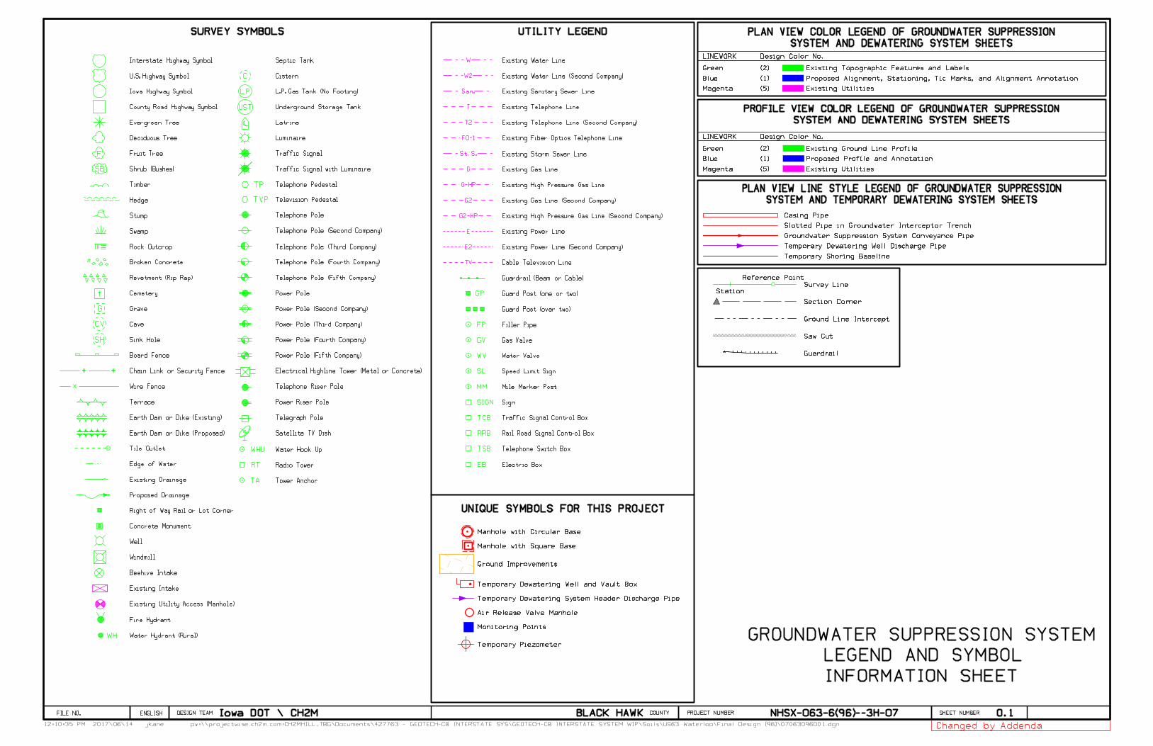
UNIQUE SYMBOLS FOR THIS PROJECT
O.1
INFORMATION SHEET
LEGEND AND SYMBOL
Existing Utilities
Existing Ground Line Profile
Existing Utilities
Existing Topographic Features and Labels
Proposed Alignment, Stationing, Tic Marks, and Alignment Annotation
Proposed Profile and Annotation
(5) Magenta
(1) Blue
(5)
(1) Blue
(2) Green
Station
Section Corner
Reference Point
Survey Line
Ground Line Intercept
Saw Cut
Magenta
Guardrail
LINEWORK Design Color No.
LINEWORK Design Color No.
GROUNDWATER SUPPRESSION SYSTEM
(2) Green
Slotted Pipe in Groundwater Interceptor Trench
Groundwater Suppression System Conveyance Pipe
Casing Pipe
Manhole with Circular Base
Temporary Dewatering Well Discharge Pipe
Temporary Shoring Baseline
Ground Improvements
SYSTEM AND TEMPORARY DEWATERING SYSTEM SHEETS
PLAN VIEW LINE STYLE LEGEND OF GROUNDWATER SUPPRESSION
SYSTEM AND DEWATERING SYSTEM SHEETS
PROFILE VIEW COLOR LEGEND OF GROUNDWATER SUPPRESSION
SYSTEM AND DEWATERING SYSTEM SHEETS
PLAN VIEW COLOR LEGEND OF GROUNDWATER SUPPRESSION
Air Release Valve Manhole
Temporary Dewatering Well and Vault Box
SURVEY SYMBOLS
Cave
TP
TVP
WHU
WH
W
San.
T
T2
St. S.
G
W2
E
E2
TV
G2
G-HP
G2-HP
FO-1
GV
WV
FP
EB
TSB
UTILITY LEGEND
Gas Valve
Water Valve
Speed Limit Sign
Mile Marker Post
Sign
Filler Pipe
Electric Box
Traffic Signal Control Box
Rail Road Signal Control Box
Telephone Switch Box
Guardrail (Beam or Cable)
Guard Post (one or two)
Guard Post (over two)
Existing Water Line
Existing Sanitary Sewer Line
Existing Storm Sewer Line
Existing Telephone Line
Existing Gas Line
Existing Telephone Line (Second Company)
Existing Water Line (Second Company)
Existing Fiber Optics Telephone Line
Existing Power Line
Existing Power Line (Second Company)
Cable Television Line
Existing Gas Line (Second Company)
Existing High Pressure Gas Line
Existing High Pressure Gas Line (Second Company)Telephone Pole
Telephone Pedestal
Telephone Riser Pole
Power Riser Pole
Electrical Highline Tower (Metal or Concrete)
Luminaire
Septic Tank
Cistern
Television Pedestal
Satellite TV Dish
Traffic Signal with Luminaire
Traffic Signal
L.P. Gas Tank (No Footing)
Underground Storage Tank
Power Pole (Third Company)
Latrine
Telegraph Pole
Power Pole
Telephone Pole (Second Company)
Telephone Pole (Third Company)
Power Pole (Second Company)
Telephone Pole (Fourth Company)
Telephone Pole (Fifth Company)
Power Pole (Fourth Company)
Power Pole (Fifth Company)
Radio Tower
Tower Anchor
Water Hook Up
Swamp
Evergreen Tree
Timber
Cemetery
Board Fence
Fruit Tree
Grave
Interstate Highway Symbol
U.S. Highway Symbol
Iowa Highway Symbol
County Road Highway Symbol
Rock Outcrop
Stump
Hedge
Shrub (Bushes)
Broken Concrete
Earth Dam or Dike (Existing)
Earth Dam or Dike (Proposed)
Terrace
Sink Hole
Tile Outlet
Deciduous Tree
Revetment (Rip Rap)
Chain Link or Security Fence
Wire Fence
Beehive Intake
Windmill
Fire Hydrant
Water Hydrant (Rural)
Existing Intake
Right of Way Rail or Lot Corner
Edge of Water
Concrete Monument
Existing Utility Access (Manhole)
Existing Drainage
Proposed Drainage
Well
SL
MM
SIGN
GP
TCB
RRB
A
SB
CV
SH
G
F
C
LP
UST
RT
TA
Monitoring Points
Temporary Dewatering System Header Discharge Pipe
Temporary Piezometer
Manhole with Square Base
Changed by Addendajkane12:10:35 PM pw:\\projectwise.ch2m.com:CH2MHILL_TBG\Documents\427763 - GEOTECH-CB INTERSTATE SYS\GEOTECH-CB INTERSTATE SYSTEM WIP\Soils\US63 Waterloo\Final Design (96)\07063096O01.dgn
DESIGN TEAM PROJECT NUMBER SHEET NUMBER COUNTY
2017\06\14
ENGLISHFILE NO. Iowa DOT \ CH2M NHSX-063-6(96)--3H-07BLACK HAWK