a custom vibration test fixture using a subwooferthe construction of automobile subwoofers is...
TRANSCRIPT
Proceedings of The 2011 IAJC-ASEE International Conference ISBN 978-1-60643-379-9
Paper 068, ENT 205
A Custom Vibration Test Fixture Using a Subwoofer
Dale H. Litwhiler
Penn State University
Abstract
There are many engineering applications for a source of controlled vibrational excitation.
Popular applications include fatigue testing of mechanical components and ruggedness and
survivability testing of electronic assemblies for harsh environments. Other applications
include vibrational energy harvesting device testing, and accelerometer testing and
calibration. There exist several piezoelectric- based energy harvesting devices that are
designed to capture random and/or single frequency vibrational energy. Testing of these
devices requires a source of controllable vibration. The static characteristics of micro
electro-mechanical system (MEMS) accelerometers can often be tested using the earth’s
gravity or centrifuge apparatus. Testing the dynamic characteristics, however, requires the
application of known vibrational acceleration inputs. Single frequency acceleration inputs
are very useful to characterize the performance of accelerometers. The applied frequency
can also be swept to determine the frequency response performance of the device under test.
Commercial vibration systems, often called shakers or shaker tables, typically use an
electromagnetic voice coil assembly to move the test fixture. Voice coils can also be found
in common audio loudspeakers. The construction of automobile subwoofers is particularly
rugged. A very useful vibration test fixture can be created by modifying a subwoofer to
include a table area to which a reference accelerometer and the component under test can be
mounted. This paper describes the design, construction and application of a subwoofer-based
vibration testing system in an undergraduate engineering technology education environment.
Some experimental results from testing of energy harvesting devices and low-g MEMS
accelerometers are also described. System component selection, performance and future
enhancements are also presented and discussed.
Introduction
As part of an investigation into vibrational energy harvesting devices, the need arose for a
controllable source of vibration. Initially, some salvaged automobile sound system speakers
were evaluated for their performance as transducers for creating the controlled vibrations.
From this evaluation, it was determined that with the proper speaker and driving signal, a
useful, inexpensive vibration test system could be created. Therefore, a custom vibration
system using a car stereo subwoofer as the transducer was designed, built and implemented
in an undergraduate engineering technology laboratory.

Proceedings of The 2011 IAJC-ASEE International Conference ISBN 978-1-60643-379-9
Figure 1 shows the custom vibration system equipment diagram. Car audio subwoofer
speakers are robust acoustic transducers with performance capabilities well suited for low
frequency vibration excitation. An area to which test specimens can be mounted was glued
onto the speaker cone. The excitation signal is produced by a laboratory function generator.
A unity gain power amplifier is used to provide the current required to drive the low
impedance of the subwoofer. A wideband accelerometer is used as the reference acceleration
measurement device. An oscilloscope is used to measure and display the accelerometer
output signal.
Figure 1. Vibration system equipment diagram
System Construction
The shaker table was fabricated using an automobile audio subwoofer speaker as the
transducer element. The frequency response range of a subwoofer is appropriate for the
desired range of the vibration table. A subwoofer was chosen for its large size and rugged
construction. The suitability of the speaker cone area for accepting the intended
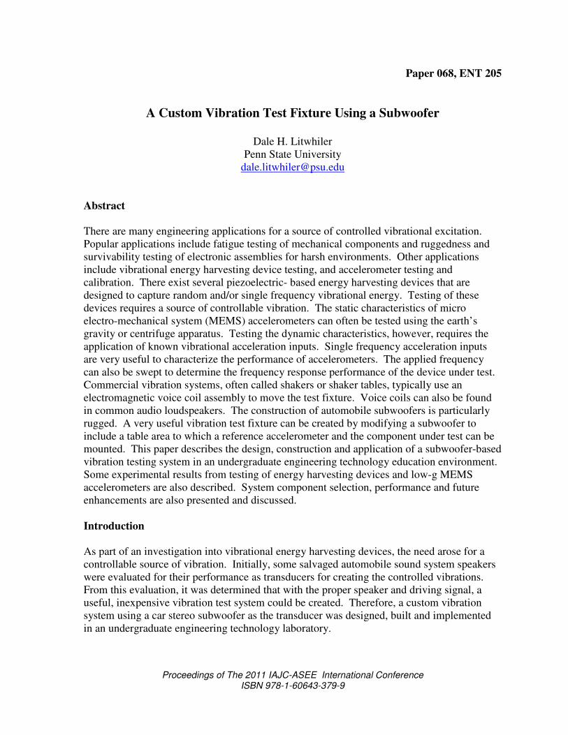
modifications was also an important consideration. In particular, the Pioneer® model TS-
SW841D, 8-inch subwoofer was selected. Some key specifications of the chosen subwoofer
are given in Table 1.[1] Figure 2 shows the subwoofer before modification.
Table 1. Pioneer subwoofer specifications
Music Power, Max 500W
Nominal Power Handling 120W
Frequency Response 30 – 1500 Hz
Nominal Impedance 4Ω
Dimensions 8-7/8” x 3”
The subwoofer was modified to create a flat shaker table surface. First, a short length (about
1 inch) of 3-inch diameter PVC pipe was bonded directly to the speaker cone material with
Goop® adhesive. Goop adhesive bonds well to PVC and the speaker cone material. The
PVC spacer helps to raise the test surface above the recessed cone area and also provides
separation from the influence of the speaker’s very strong magnet. A 0.25 inch thick disk of
Proceedings of The 2011 IAJC-ASEE International Conference ISBN 978-1-60643-379-9
Figure 2. Pioneer Subwoofer
Delrin® acetal resin was used as the shaker table mounting surface. The disk is fastened to
the PVC pipe using eight machine screws arranged in a bolt circle around the edge. The
Delrin disk provides an interchangeable and replaceable surface with excellent stiffness and
machining properties. The device to be tested is mounted to the shaker table using machine
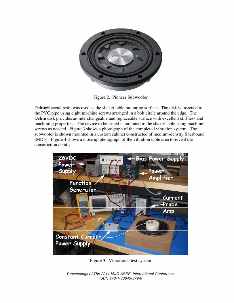
screws as needed. Figure 3 shows a photograph of the completed vibration system. The
subwoofer is shown mounted in a custom cabinet constructed of medium-density fiberboard
(MDF). Figure 4 shows a close up photograph of the vibration table area to reveal the
construction details.
Figure 3. Vibrational test system

Proceedings of The 2011 IAJC-ASEE International Conference ISBN 978-1-60643-379-9
Figure 4. Subwoofer shaker table detail
The vibration amplitude of the shaker table is measured by a calibrated reference
accelerometer. The PCB Piezotronics model 333B30 accelerometer was chosen for this
application due to its low cost, sensitivity and small size and mass. The 333B30 can be seen
mounted to the shaker table surface in Figure 4. Table 2 shows an excerpt from the 333B30
datasheet.[2]
Table 2. 333B30 accelerometer specifications
PARAMETER ENGLISH SI
Sensitivity(± 10 %) 100 mV/g 10.2 mV/(m/s²)
Measurement Range ± 50 g pk ± 490 m/s² pk
Frequency Range(± 5 %) 0.5 to 3000 Hz 0.5 to 3000 Hz
Resonant Frequency ≥ 40 kHz ≥ 40 kHz
Excitation Voltage 18 to 30 VDC 18 to 30 VDC
Constant Current Excitation 2 to 20 mA 2 to 20 mA
Output Bias Voltage 7 to 12 VDC 7 to 12 VDC
The accelerometer requires a constant current power supply with a compliance voltage
between 18 and 30 VDC. The accelerometer then produces an output DC level of 7 – 12
VDC. The dynamic acceleration output signal is superimposed on the DC bias output. The
power supply was also custom-designed and built in the engineering technology laboratory.
Figure 5 shows the schematic diagram of the constant current power supply.

Proceedings of The 2011 IAJC-ASEE International Conference ISBN 978-1-60643-379-9
1N4002
Red LED
1N5306 (2.2mA)
10µF BNC
To Scope
BNCTo
Accelerometer
DC Power
Supply
Figure 5. Constant current power supply schematic
As shown in Figure 5, the current regulator diode, 1N5306, provides the required constant
current bias for the accelerometer. In operation, the DC input voltage is set to 26VDC while
the DC output voltage is monitored with a DVM. The DC output voltage typically settles at
about 10.9VDC. When the DC output voltage settles, the accelerometer is ready for use.
The 10µF capacitor allows only the AC part of the accelerometer output to pass to the
oscilloscope input. The user can also access the combined DC and AC output of the
accelerometer at the port which is normally connected to the DVM as shown.
The magnitude and frequency of vibration is controlled by a function generator. The
function generator is set to produce a sine wave output with zero offset. A power amplifier is
needed to provide the current drive required by the low impedance of the subwoofer. The
vibration system will find application at frequencies below the audio band therefore a DC-
coupled amplifier was desired. The Feedback® model TK2941B unity voltage gain power
amplifier was used. The amplifier was part of an educational sensors package already in use
in the engineering technology laboratories.
System Performance
To characterize the performance of the subwoofer vibration system, the frequency response
of the table acceleration versus speaker input voltage was measured. The input voltage was
held nearly constant at about 400 mVrms for each frequency tested. Figure 6 shows a plot of
the measured frequency response. The data shows a distinctive resonant peak near 45Hz.
Therefore, care must be taken when applying signals with frequency components around
45Hz. The frequency response also indicates that the system has a useful in excess of 180
Hz.

Proceedings of The 2011 IAJC-ASEE International Conference ISBN 978-1-60643-379-9
0.00
0.50
1.00
1.50
2.00
2.50
3.00
0 50 100 150 200
g /v
olt
Frequency (Hz)
Figure 6. Vibration table acceleration frequency response
The input impedance frequency response was also measured. A Tekronix® active current
probe was used to measure the subwoofer input current. The speaker input voltage was
measured using a standard voltage probe. Again, the input voltage was held nearly constant
at 400 mVrms. The frequency response of the magnitude ratio of measured speaker input
voltage to input current (input impedance) is shown in Figure 7. The input impedance data
indicates a distinct, high-Q, electrical resonance near 42Hz.
0.00
2.00
4.00
6.00
8.00
10.00
12.00
14.00
0.00 50.00 100.00 150.00 200.00
Imp
edan
ce (
Oh
ms)
Frequency (Hz)
Figure 7. Subwoofer input impedance frequency response

Proceedings of The 2011 IAJC-ASEE International Conference ISBN 978-1-60643-379-9
Example Applications
Energy Harvesting
The Joule-Thief TM
JTRA-e5mini energy harvesting module manufactured by AdaptivEnergy
is a random vibrational energy capturing and storage device. It finds application in vehicular
vibration powered sensor systems. The JTRA-e5mini contains a tuned cantilever spring-
mass system with an integral piezoelectric generator. To investigate the performance of this
device, the evaluation kit was used. As shown in Figure 8, the evaluation kit contains a
micro-power wireless communication board, USB communication dongle and application
software. The evaluation kit allows the user to remotely monitor and chart the average power
output of the JTRA-e5mini.[3]
Figure 8. Joule-Thief TM
JTRA-e5mini Evaluation Kit
The Joule Thief JTRA-e5mini energy harvesting unit was mounted to the subwoofer shaker
table using a top clamping bar arrangement as shown in Figure 9. The performance of the
energy harvester was evaluated for several levels of sinusoidal vibration at about 15 Hz. The
output of the reference accelerometer was measured using a digital oscilloscope to determine
the vibration level. Figure 10 shows a plot of the data obtained from this test.

Proceedings of The 2011 IAJC-ASEE International Conference ISBN 978-1-60643-379-9
Figure 9. Joule Thief JTRA-e5mini mounted to shaker table.
0
0.01
0.02
0.03
0.04
0.05
0.06
0.07
0.08
0.09
0.1
0 0.05 0.1 0.15 0.2 0.25 0.3 0.35 0.4 0.45
Av
era
ge
Po
wer
(m
W)
Acceleration (g rms)
Figure 10. Joule Thief JTRA-e5mini evaluation data plot
MEMS Accelerometers
A custom centrifuge system for the evaluation of the static performance of MEMS low-g
accelerometers has been presented in [4]. To evaluate the dynamic performance, the
accelerometers were mounted to the subwoofer shaker table. The output for each
accelerometer was compared with that of the reference accelerometer. The Freescale
MMA2201D (±40g) and MMA2260D (±1.5g) MEMS accelerometers were tested. Figure 11
shows the test setup for the MEMS devices.

Proceedings of The 2011 IAJC-ASEE International Conference ISBN 978-1-60643-379-9
Figure 11. MEMS accelerometer test setup
The MMA2201D has a nominal sensitivity of 50mV per g. The acceleration output signal is
superimposed on a zero-g bias voltage of 2.5V when powered from 5V. The frequency
response of the MMA2201D versus the reference accelerometer is shown in Figure 12. The
MMA2201D was found to have a very flat frequency response with excellent bandwidth.
0.00
0.10
0.20
0.30
0.40
0.50
0.60
0.70
0.80
0.90
1.00
0 50 100 150 200
Rat
io o
f M
MA
220
1 t
o r
efer
ence
ac
cele
rom
eter
ou
tput
Frequency (Hz)
Figure 12. Frequency response data for MMA2201D
The MMA2260D has a nominal sensitivity of 1.2V per g. The acceleration output signal is
superimposed on a zero-g bias voltage of 2.5V when powered from 5V. The frequency
response of the MMA2260D versus the reference accelerometer is shown in Figure 13. The

Proceedings of The 2011 IAJC-ASEE International Conference ISBN 978-1-60643-379-9
MMA2260D was found to have a bandwidth of about 50Hz which is the nominal value given
in the manufacturers datasheet.
1.00
10.00
10 100
Rati
o o
f M
MA
22
60
D t
o R
efer
ence
Acc
eler
om
eter
Ou
tpu
t
Frequency (Hz)
Figure 13. Frequency response data for MMA2260D
Future Work
Work continues with making the vibration test system more useable by students with less
supervision. This includes developing LabView software to create the subwoofer input
signals from a USB sound card device. This software will allow for the creation of complex
waveforms and vibration profiles.
Some nonlinear vibrational behavior was observed at lower frequencies, especially those
below 10Hz. Work is continuing to test various methods of correcting the nonlinear behavior
to obtain more repeatable acceleration waveforms.
Conclusions
A vibration test apparatus using a modified subwoofer speaker was designed and fabricated.
The modifications were quite simple and inexpensive. The vibration system was
characterized and found to have very acceptable performance. The system was used to
evaluate the performance of an energy harvesting device. MEMS accelerometers were also
tested using the system with excellent results.
Acknowledgments
Proceedings of The 2011 IAJC-ASEE International Conference ISBN 978-1-60643-379-9
The author would like to thank Jordan Waite for his help in developing hardware and
software for this project. Jordan is a third-year student in the electro-mechanical engineering
technology program at Penn State Berks.
References
[1] Pioneer Electronics TS-SW841D subwoofer datasheet available:
http://www.pioneerelectronics.com/PUSA/Products/CarAudioVideo/Subwoofers/Shal
low/TS-SW841D?tab=B
[2] PCB Piezotronics 333B30 accelerometer datasheet available:
http://www.pcb.com/spec_sheet.asp?model=333B30&item_id=9183
[3] AdaptivEnergy JTRA-e5mini datasheet
available:http://www.adaptivenergy.com/docs/WP_AE_01_RandomVibeWSN.pdf
[4] Litwhiler, D. H., “MEMS Accelerometer Investigation in an Undergraduate
Engineering Technology Instrumentation Laboratory,” Proceedings of the American
Society for Engineering Education Annual Conference and Exposition, 2010.
Biography
DALE H. LITWHILER is an Associate Professor at Penn State, Berks Campus in Reading,
PA. He received his B.S. from Penn State University, his M.S. from Syracuse University,
and his Ph.D. from Lehigh University, all in electrical engineering. Prior to beginning his
academic career, he worked with IBM Federal Systems and Lockheed Martin Commercial
Space Systems as a hardware and software design engineer.