a coupled geomechanical, acoustic, transport and sorption …...
TRANSCRIPT

A Coupled Geomechanical, Acoustic, Transport and Sorption Study of Caprock Integrity in
Carbon Dioxide (CO2) Sequestration
DE-FE-23223
Manika Prasad, CSMCo-I: Bill Carey (LANL), Ronny Pini (Imperial College)
Post-Docs & Students: LANL: L. Frash; CSM: N. Joewondo, K. Livo, A. Hasanov, Y. Zhang
U.S. Department of EnergyNational Energy Technology Laboratory
Mastering the Subsurface Through Technology Innovation, Partnerships and Collaboration:Carbon Storage and Oil and Natural Gas Technologies Review Meeting
August 1-3, 2017

2
Presentation Outline
• Objectives and motivation• Experimental Updates
– NMR experiments– Adsorption measurements– Permeability and acoustics measurements;
simulations
• Accomplishments to date• Future work

3
Hypothesis and ObjectivesHypothesis:
• Mechanical damage to shales does not necessarily lead to high permeability and substantial leak rates
Objectives:• Determine the behavior of intact and fractured caprocks when
exposed to supercritical CO2 at elevated pressures
• Quantify adsorption, strain and acoustic properties of shales with sorbed CO2
• Provide framework for monitoring, verification and accounting (MVA) efforts of CO2 sequestration and its effect on caprock

4
Motivation
• Quantification of hydrophilic and hydrophobic pores of shales
Preferential sorption of fluids depends on polarity of surfaces
S. Kumar

TECHNICAL STATUS
5

I: NMR EXPERIMENTS Kurt Livo, Ph.D. cand
6

NMR CO2 Injection
7(Machining courtesy of the Colorado School of Trades)
• NMR Measurements– 2 MHz– 0.05 Tesla– Laplace non-negative least
square (NNLS) fitting inversion
• Pressure Vessel Design– 9 Electrical inlet lines– 2 Fluid flow lines– 5000 psi tested pressure– 10000 psi rated pressure– 1 in. core capability
NMR Investigation of CO2 injection

CO2 Berea Core Injection
• CO2 injection at 900 psi• Measurements occurred for 3.5
days• Depressurization measurements for
16 hours
• Mineralization verified with micro-CT images
8
Torlon Pressure Vessel
Berea core
Berea chip for CT
NMR Investigation of CO2 injection
CO2DI H2O

FLUID-PRESSURE RESPONSEI: NMR EXPERIMENTS
9

T2 Pressure Variations in Bulk Fluids
10
Large changes in T2-relaxation with pressure in both fluidsT2 relaxation changes are irreversible in DI water and reversible in mineral oil
30000 30000
DI-Water Mineral Oil
NMR Investigation of CO2 injection

CO2 INJECTION RESPONSEI: NMR EXPERIMENTS
11

Berea Sst Saturated with CO2
12
NMR Investigation of CO2 injection
• T2 relaxation time changes from 360 ms to 18 ms• T2 signal amplitude reduces as CO2 enters solution

Bulk Water with CO2 Injection
13
NMR Investigation of CO2 injection
• T2 relaxation time changes from 1.8 sec to 0.2 sec • T2 signal amplitude does not reduces much
Large pore range
Small pore range

POSSIBLE EXPLANATIONSI: NMR EXPERIMENTS
14

Mineralization Effects?
15
NMR Investigation of CO2 injection
CT Image before CO2 exposure CT Images after CO2 exposure
(Courtesy of Mandy Schindler)

T2 Relaxation with varying pH
16
NMR Investigation of CO2 injection
pH variation of the fluid phase does not effect NMR response and cannot account for the large spectra shift due to CO2 in solution

Solubility of CO2 in water
17Pruess, 2005

Viscosity Change
18
Viscosities change: [(1 - x) H2O + x CO2]
McBride-Wright et a., 2014

II: LOW PRESSURE SORPTIONNerine Joewondo, M.S. cand
19

Utica Shales: N2 adsorption
20
Low Pressure Nitrogen Adsorption
Nitrogen adsorption isotherms PSD of Utica samples
TOC: 2-3.2 wt. %Pore Size Distribution (PSD) from Density Functional Method (DFT) (radius > 0.7 nm)
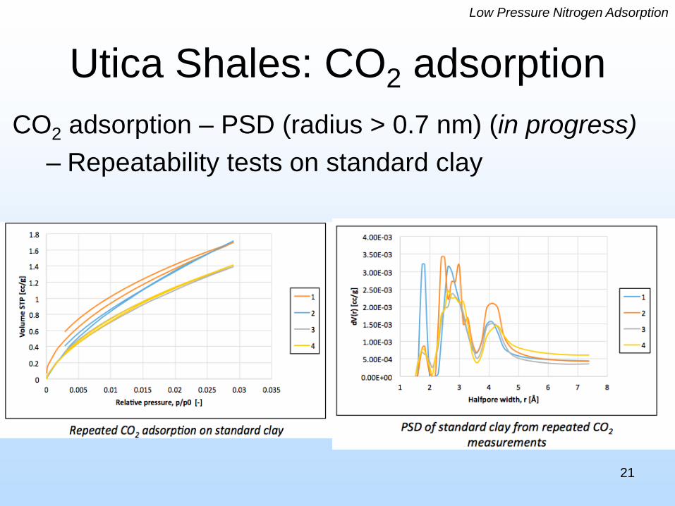
Utica Shales: CO2 adsorption
21
Low Pressure Nitrogen Adsorption
CO2 adsorption – PSD (radius > 0.7 nm) (in progress)– Repeatability tests on standard clay

III: PERMEABILITY AND ACOUSTICS
22

Experimental Apparatus
23
Permeability and Velocity Test

Experimental Apparatus
24
Permeability and Velocity Test
1.5”

Experimental Procedure
25

Transport and Poroelastic Properties
26

Permeability vs. Confining Pressure
27
Permeability and Velocity Test

Velocity vs. Confining Pressure
28
Permeability and Velocity Test
Saturated waterCO2
dry

Accomplishments to Date
INSTRUMENT CONSTRUCTION:– Constructed pressure and flooding setup for NMR and CT
imaging with capability for simultaneous acoustic or conductivity measurements
– Constructed pressure setup for supercritical sorption experiments with capability for simultaneous acoustic or conductivity measurements
EXPERIMENTS:– NMR relaxations with pressure in fluids & rocks + fluids– Permeability and acoustic measurements with pressure– CO2 sorption with various fluids (N2, CO2, H2O+ CO2) - with
acoustics – in progress 29

Synergy Opportunities
– Calibrate NMR signals with changes in the fluid versus changes in the rock due to rock – fluid interactions. Relevance: CO2 operations BUT oil & gas operations too
– Calibrate seismic models with partial saturation due to mineralogy – dependent preferential sorption of CO2and water. Relevance: Indirect fluid monitoring operations
– Joint acoustic – permeability changes with CO2 before and after shearing. Relevance: caprock changes with stress changes
30

APPENDIX
31

Future Work
32
• Simultaneous high PT sorption with acoustic & resistivity; Calibrate seismic models with partial saturation with mineralogy – dependent preferential sorption of CO2 and water.
• Theoretical models of physical process in shales; multilayer adsorption; Compare permeability of CO2, N2, and H2O in fractured shale
• Compile and compare permeability, acoustics, resistivity, and sorption data• Distinguish between adsorption effects on relaxivity and fluid pressure
effects; Quantifying adsorbed volume, diffusion coefficients, and acoustic measurements during pressurization; make T1-T2 maps
• Calibrate NMR signals with changes in the fluid versus changes in the rock due to rock – fluid interactions.
• Joint acoustic – permeability changes with CO2 before and after shearing.

33
Background• Carbon capture and storage in deep geological settings
• Caprock seals and prevents buoyant migration of CO2
– Permeability of caprock ~ Nanodarcy– Permeability of tight-gas shales ~ Nano to Microdarcy
• CO2 injection changes the state of stress in reservoir rocks and in caprocks
• Could faults or fractures develop in caprocks that allow CO2 transport and escape?

Accomplished to Date
34
Completed:
• Experimental Setup
• Subcritical Adsorption on various fluids
• High pressure adsorption with CO2 on a shale and a clay sample
• Acoustic tests during sorption
• NMR experiment during CO2 injection
Ongoing:
• Acoustic Tests
• Equation of state calculations
• High pressure and temperature tests
• Triaxial tests for strength and fracture permeability