a controller for the littledog quadruped walking on rough
TRANSCRIPT

A Controller for the LittleDog Quadruped Walking on Rough Terrain
John R. Rebula, Peter D. Neuhaus, Brian V. Bonnlander, Matthew J. Johnson, Jerry E. PrattFlorida Institute for Human and Machine Cognition, Pensacola, Florida 32502, USAhttp://www.ihmc.us/research/projects/LearningLocomotion/ ([email protected])
Abstract— We present a controller for a quadrupedal robotstatically walking on known rough terrain. The controller hasboth deliberative and reactive components for task specificcontrol issues, such as impassable terrain and unmodeled footslippage. The controller architecture supports multiple gaits,and we present both a stable omnidirectional gait and a fasterdirectional gait. The robot successfully negotiates obstacles upto 7.5 cm (≈40% leg length) tall and navigates over rockyterrain.
I. INTRODUCTION
This paper describes the design and implementation detailsof a controller for the Boston Dynamics LittleDog quadrupedrobot walking over rough terrain. The LittleDog (Fig. 1)has 12 actuated degrees of freedom with high gain servomotors powering each joint. In order to focus on the con-troller and not be distracted by the complex problem ofaccurately sensing the robot and environment, we employa Vicon motion capture system comprised of six camerasfixed around the experimental area and a computer to processimages. The LittleDog has 22 reflective balls attached tothe body and legs. The motion capture system detects thesemarkers and determines the robot pose and joint angles fromknown models. In addition, the LittleDog also has an inertialmeasurement unit which provides measurements of linearacceleration and angular velocities which are accurate overshort time periods. This data is then fused with the motioncapture data, which accounts for drift and integration errors.Predefined terrain boards can also be placed into the areawith motion capture markers to identify the location. One ofthe terrain boards is shown in Fig. 2. Each terrain board has acorresponding high resolution model, which when combined
Fig. 1. The BDI LittleDog robot. Each leg has three actuated degreesof freedom, two at the hip (θhip,x, θhip,y), and the knee joint θknee.The whole system therefore has 18 degrees of freedom, three per leg plus(x,y,z,roll,pitch,yaw) of the body.
Fig. 2. An example terrain board (left) with a rendering of its correspondingmodel
with the motion capture data, provides an accurate model ofthe robot and its environment updated at 100Hz. The task isto successfully navigate across the rough terrain to reach anarbitrarily specified goal.
A. Control Issues
• Impassable Terrain: A robot traversing over roughterrain may encounter an obstacle that is kinematicallyimpossible for the robot to traverse. This situationcreates a search problem over possible paths over theterrain that requires a deliberative path planner to exploitterrain knowledge.
• Foot Slippage: One implication of rough terrain is themagnification of error in foot contact models. Smallfoot slips, even on locally flat terrain, can lead to afoot falling off of an edge of the terrain, resulting inunexpected stances and a possible loss of stability.
• Accidental Collision: Rough terrain can obstruct aleg’s path while swinging from one location to another.In addition, even with fixed foot positions, shiftingthe body center of mass can result in a leg segmentcontacting the terrain accidentally. Such collisions mustbe sensed and accounted for in a controller.
• Modeling Errors: Stability of a statically walkingquadruped is very sensitive to the center of mass loca-tion, and therefore normally requires an accurate modelof the robot. Due to variation during the LittleDog cali-bration procedure it was desirable to design a controllerrobust to model error.
• Sensor Errors: The motion capture system occasion-ally fails to locate some of the markers, resulting inmomentary loss of robot position information on theterrain. Although filtering the motion capture outputmitigates this problem, a failure at a critical time suchas foot placement planning can lead to robot instabilityif the algorithm depends too heavily on the assumption

of perfect sensing.
B. Previous Work
Due to the difficulties involved with legged robots,quadrupedal locomotion on rough terrain has mostly beenstudied in simulation. For example, the task of searchingthrough known terrain with impassable zones lends itselfto formulation as a search problem, so this problem isoften treated only in simulation with simplified models as in[19]. Oomichi and colleagues have worked on determiningsuitability of terrain for legged locomotion as part of ahierarchical controller [18]; their path and gait planningalgorithm validation was again performed in simulation.Another approach avoids the issue of sensing the environ-ment and path planning by writing controllers that adaptin real time to the given terrain. Prajoux and Martins [24]discussed a controller that adapts to foot slippage using forcecontrol in simulation. Estremera and de Santos approachedquadrupedal rough terrain navigation by combining gaitsthat maintain constant body movement with gaits that breakthe movement phases into separate body movement and legmovement phases [7]. The algorithm was validated using arotationally symmetric robot on level terrain with softwaredefined “forbidden zones” and the hybrid gait was derivedassuming pitch and roll remained close to zero. Our robot isasymmetric and overcoming the terrain requires significantpitch and roll so the algorithm was not directly applicable.Their more recent work [8] presents a gait that does functionon modestly uneven terrain (6.5 cm step compared to 48 cmextended leg length), but the terrain is composed of simplesteps.
C. Proposed Solution
We present a controller that combines aspects of delibera-tive and reactive controllers to address the issues with roughterrain quadrupedal locomotion outlined in section I-A. Themain loop of the controller is a deliberative algorithm thatplans the next foot step and determines the motion of thelegs and body to achieve the step while maintaining stability.This deliberative layer addresses the problem of impassableterrain but neglects foot slippage, accidental collision, andmodeling and sensor errors. Reactive modules were createdto address specific problems that arose from these issues.
II. DELIBERATIVE MODULES
Considering the issue of impassable terrain and the factthat we have fairly accurate sensor information, we felta deliberative layer was appropriate as the basis of ourcontroller.
A. State Machine
The deliberative controller was implemented as a statemachine, depicted in Fig. 3. The first phase is Gait Selection,which chooses the next leg to swing. The second phase is anoptional body shift with all four feet on the ground, whichwe refer to as a Quad Shift. The Quad Shift phase movesthe body to position the center of gravity (COG) inside
Fig. 3. A partial state machine of a single swing leg cycle. The algorithmstarts by deciding which leg to swing in gait generation. The body is thenshifted on all four legs during Quad Shift to position the COG inside thesupport triangle of the non swing feet. The robot then executes the swingwhile possibly shifting the body.
the upcoming support polygon to ensure stability. The thirdphase is the Swing, which swings the leg and may involvea simultaneous body shift. This simple three phase modelallowed us to achieve several gaits. The only knowledgeshared between these states is the swing leg identified inthe gait generation phase.
B. Stance List Control
We use the concept of a stance to define the configurationof the robot at any point in time. The stance is composedof body position and orientation and the location of all fourfeet. Any state that results in motion will output a series ofwaypoint stances that start with the current stance and endwith the final desired stance of the state. Stances are thengenerated between these waypoints, smoothly transitioningfrom one to the next such that playback at 100Hz generatesthe desired position trajectories. These stances are thenplayed back by performing inverse kinematics and passingthe resulting desired joint angles to a low level servo motorcontroller each control cycle. The transition to the next stateoccurs when all stances in the current stance list have beenplayed. The reactive modules discussed in III then modifythe stances as they are replayed.
C. Gait Selection
For terrain that allows a fairly straight path, we use thestandard gait identified by Muybridge [17]. This gait issufficient to provide reasonably fast movement on flat terrainand adapts well to variation in mildly rough terrain. However,as the terrain becomes increasingly complex, it is likely thata straight path may not be possible. For this terrain we usean omnidirectional gait selection algorithm that chooses thenext leg to swing based on three simple heuristics.
start with all legsIF direction has not changed
THEN remove the previous swing legIF lifting a leg leaves an insufficient
support polygonTHEN remove it
CONSIDER the remaining legsCHOOSE the leg which can move
furthest in the desired direction

D. Quad Shift Phase
The Quad Shift phase ensures stability of the initialsupport triangle of the upcoming swing phase by shiftingthe body center. In practice, it is useful to minimize the timespent in the Quad Shift phase since no leg is swinging. To dothis the body shifts the COG along the shortest path acrossthe trot line, defined as as the line segment connecting thetwo support legs not diagonal to the swing leg, allowing fora stability margin as shown in Fig. 4. Using a fixed gaitthis algorithm results in a shift only on hind leg swings,as the COG is already inside the support polygon after thehind swing. As the terrain becomes increasingly difficult,speed becomes less of an issue than stability and kinematicreachability. For this type of terrain the desired shift positionis the centroid of the upcoming support polygon as shownin Fig. 5; this sacrifices speed to maximize stability foromnidirectional walking.
E. Swing Phase
The swing phase determines a trajectory for the swing legto take and possibly a shift as well. Since the swing phasemust generate the swing foot position, it must classify theterrain as passable or impassable. Therefore, the terrain eval-uator is presented in this section along with the submodulesthat generate the shift and swing trajectory.
1) Terrain Evaluation: A terrain scorer classifies potentialfoot placement at a given point on the terrain as acceptableor unacceptable. The scorer checks small grids around thepoint and compares the heights to the height at the point.It then rejects the point if it is on too large of a slope, too
Fig. 4. The Fast Quad Shift algorithm. This ensures the smallest QuadShift movement and minimizes the time spent in the quad shift phase.
Fig. 5. The Stable Quad Shift algorithm. This requires a longer quad shifttime but results in a more stable stance and puts the robot in a good positionto move in any direction.
close to the top edge or the base of a cliff, or inside of ahole. The grid sizes for each check and the height differencethresholds are parameterized and have been tuned to provideacceptable classifications for the LittleDog robot. For runtime efficiency, the scorer precomputes these points on afine (0.5mm) grid at startup and stores them in a table. Animage of the scored terrain is shown in Fig. 6.
2) Shift Generation: Part of our task is to maximizespeed while traversing the rough terrain. Our initial terrainselections were a single step and some fairly uniform heightrocks. While these required some care in foot placement, theypermitted a continuous standard gait with the body staying inconstant motion while traversing the terrain. Since the terrainallowed reasonably straight traversal without large directionchanges, we maximized our speed by making use of therobot’s full body range to extend its reach during the swingphase. The swing shift algorithm is
IF hind leg:THEN shift half way to the
midpoint of the frontstability boundary
IF front leg:THEN shift to the midpoint of
the front stability boundary
The resulting behavior stretches the body forward during theswing phase to obtain a further reach as shown in Fig. 7.Notice that a front leg swing shift will shift directly to the
Fig. 6. An example of the terrain scorer run on the tilted roughterrain board. The painting resolution is [5mm]. The blue points representacceptable foot locations; the red points represent unacceptable locations.
Fig. 7. The swing shift for a front leg swing phase.

Fig. 8. An example set of points considered for the current foot target.The red ball is the initial candidate, the blue and black balls are subsequentcandidate points. The green balls represent current foot locations. The bluesquares on the terrain represent acceptable foot locations.
front stability boundary of the support triangle – a marginallystable position. This allows the robot to fall onto the frontleg, a characteristic of quadrupeds that the controller takesadvantage of to maximize forward movement.
The shift generator also determines the desired pitch andheight of the stance so that the swing leg can clear the terrainand reach the target location. The initial target pitch of thebody is zero degrees. The target body height is an average ofthe lowest body height such that no knee joint angle is lessthan a minimum threshold, and the highest body height suchthat no leg is over extended. When adjusting the pitch andheight from these targets, the terrain in front of the swing legis scanned to determine the highest point. A check is thenperformed to determine if there is enough clearance basedon the target pitch and height for the swing leg to step overand onto the highest point. If there is insufficient clearance,the pitch of the robot is adjusted up to a maximum allowedpitch. If there is still insufficient clearance, the height of therobot is adjusted up to the maximum allowed without overstretching a leg.
3) Foot Swing Generation: The swing generator deter-mines the desired trajectory of the swing foot. We attemptto place the foot at the furthest possible position in thedirection of travel for the current height. The initial estimateassumes level terrain and uses trigonometry to determine themaximum reach. We enumerate possible foot locations in agrid running backwards from the maximum reach estimate,choosing the first acceptable foot location found. An exampleswing enumeration is shown in Fig. 8. A foot location isconsidered acceptable if it is kinematically reachable, onacceptable terrain, and does not result in the swing legcontacting the terrain. In the case that no point is consideredacceptable, the maximum reach point is chosen. Once thetarget point is found the swing generator creates a set ofwaypoints for the swing leg to pass through. A typical pathis depicted in Fig. 9. These waypoints are set based onterrain, and for rough terrain the step height is set to themaximum kinematically reachable value. On rough terrain,the robot’s stability is very sensitive to errors in properlylocating the swing foot on the terrain. Errors caused by issuessuch as those described in section I-A integrate over the
Fig. 9. The swing leg foot trajectory. The trajectory consists of threesegments. The first is a straight line upwards. The second is a parabolawith an apex at the desired step height. The final segment is a straight linedown to the end point.
swing leading up to the final foot placement. To addressthis we replan the final foot placement when we begin tolower the foot. This new trajectory is based on the currentobserved stance and yields a swing trajectory that can moreaccurately place the foot.
III. REACTIVE MODULES
Due to the control issues outlined in section I-A, thedeliberative algorithm alone fails under certain conditions.These failure modes were identified and addressed by spe-cific modules with control components combining aspects ofreactive and deliberative schemes appropriate to the problemthey address.
A. Pitch and Roll Controller
During stance list playback, foot slippage can cause dis-crepancies between the current stance of the robot and thecurrent desired stance in the list. These foot location errorstranslate into pitch and roll errors, and the pitch and rollcontroller reactively cancels these errors by adjusting eachsupport leg’s extension.
B. Hind Leg Tip Detector
The shift generator is designed to maintain the center ofmass inside the support polygon of the upcoming swing, butdue to modeling errors the Fast Quad Shift algorithm doesnot always succeed. In the case of front leg swings, this is notdisastrous because the robot falls forwards onto the swing legwhile attempting to shift forwards, effectively catching itself.In the case of a rear swing leg, particularly when the body ispitched up to overcome an obstacle, the robot can tip backonto the rising swing leg and roll over. We solve this problemreactively by monitoring the pitch and roll dynamics duringthe lifting phase of hind leg swings to determine if the robotis tipping back. If this condition is detected, the stances thathave been executed since the start of the swing are replayedbackwards, thus putting the leg back on the ground. Once theleg is back in its starting position, the body is repositioned bymoving the center of mass closer to the centroid of the stancefeet polygon and the swing is recalculated and executed.

Fig. 10. A time lapse of the robot traversing rough terrain. The robot was given a target destination on the far rock terrain board and began facing thedesired direction. Images are evenly spaced in time, total run time is 47 sec.
Fig. 11. A graph of the terrain height and the center of mass trajectory. The rectangles represent the position and attitude of the robot body as it traversesthe terrain from left to right, corresponding to the images in Fig. 10
Fig. 12. An overhead graph of the body center of gravity and footstep positions. The red, green, blue, and black points represent the front left, frontright, hind right, and hind left steps, respectively.
Fig. 13. A measure of static stability SSM throughout the run. The stability is measured as the shortest distance of the horizontally projected COG fromthe edge of a support polygon. Notice the stability margin periodically drops below zero at the end of each front leg swing.
Fig. 14. A graph of the filtered forward velocity x of the robot body center throughout the run.
C. Soft Force Control
With a high gain position control scheme, small errorscan cause the robot to punch into the ground and destabilizeitself or stop the foot before touching down on the terrain.We use a compliant foot placement algorithm to guaranteeboth that the foot is on the ground before the transition tothe next phase and that the placement is smooth enoughto avoid accidentally shifting the body. We switch fromposition control of the leg to a pseudo-force control when thefoot is close to touching the ground, and generate a desiredtrajectory from the current foot location to the target point onthe ground. When in pseudo-force control mode, a desiredcurrent (torque) is given to the knee joint such that the footmoves down with a constant desired force. The desired pathof the foot is parameterized by the knee joint so as the footmoves down and the knee joint changes, the desired positionof the foot can be determined. From the desired position ofthe foot, the desired values for the two hip joints can becalculated. The swing state is over when the velocity of theknee joint is close to zero or the leg is fully extended.
IV. LOW LEVEL CONTROL
The main controller runs on an offboard computer at100Hz with a wireless connection to the robot. Stances aregenerated by the deliberative modules for playback on therobot, and are then modified by the reactive control modulesto account for accumulated error. Every control tick thecontroller performs inverse kinematics on the desired stanceto produce desired joint positions. These positions are thentransmitted to the onboard computer on the robot, whichperforms low level PD control on the individual joints of therobot at 500Hz. Gains of Kp = 30Nm
rad and Kd = 0.6Nmsrad
were used on in the low level controller.
V. RESULTS
The robot was run using the Fast Quad Shift algorithmwith a standard gait generator. A time lapse of the robotnavigating rough terrain is shown in Fig. 10. A correspondingprofile view of the center of mass position in relation tothe terrain is depicted in Fig. 12. The static stability marginSSM [16] for this run, which is defined as the distance ofthe center of mass of the robot projected onto the supporttriangle to the nearest edge of the support triangle is shown inFig. 13. Notice the stability margin periodically drops belowzero at the end of each front leg swing.
VI. CONCLUSIONS AND FUTURE WORK
A. Conclusions
This paper describes a controller for the LittleDog robotwalking on rough terrain. We identified several controlissues and presented a controller that combines deliberativeand reactive modules to address these issues. The basis ofthe controller is a deliberative algorithm that chooses footlocations and generates a body shift and swing motion.Reactive modules were added to address specific problemsarising from foot slippage and other unmodeled errors. Thesemonitor critical events such as hind foot liftoff and foot
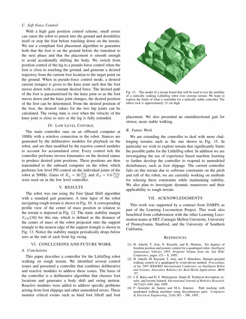
Fig. 15. The model of a terrain board that will be used to test the mobilityof a statically walking LittleDog robot over extreme terrain. We hope toexplore the limits of what is reachable for a statically stable controller. Thetallest rock is approximately 15 cm high.
placement. We also presented an omnidirectional gait forslower, more stable walking.
B. Future Work
We are extending the controller to deal with more chal-lenging terrains such as the one shown in Fig. 15. Inparticular we wish to explore terrain that significantly limitsthe possible paths for the LittleDog robot. In addition we areinvestigating the use of experience based machine learningto further develop the controller to respond to unmodeleddisturbances, such as foot slippage. The current controllerfails on this terrain due to software constraints on the pitchand roll of the robot; we are currently working on methodsfor relaxing these constraints while maintaining stability.We also plan to investigate dynamic maneuvers and theirapplicability to rough terrain.
VII. ACKNOWLEDGMENTS
This work was supported by a contract from DARPA aspart of the Learning Locomotion Project. This work alsobenefitted from collaboration with the other Learning Loco-motion teams at MIT, Carnegie Mellon University, Universityof Pennsylvania, Stanford, and the University of SouthernCalifornia.
REFERENCES
[1] H. Adachi, T. Arai, N. Koyachi, and K. Homma. Six degrees offreedom position and posture control for a quadruped robot. IntelligentAutonomous Vehicles 1995. Postprint Volume from the 2nd IFACConference, pages 133 – 8, 1995.
[2] H. Adachi, M. Koyachi, T. Arai, and Y. Shinohara. Human-operatedwalking control of a quadruped by event-driven method. Proceedingsof the 1997 IEEE/RSJ International Conference on Intelligent Robotand Systems. Innovative Robotics for Real-World Applications. IROS’97.
[3] J. E. Bares and D. S. Wettergreen. Dante II: Technical description, re-sults, and lessons learned. International Journal of Robotics Research,18(7):621–649, July 1999.
[4] P. Gonzalez de Santos and M.A. Jimenez. Path tracking withquadruped walking machines using discontinuous gaits. Computers& Electrical Engineering, 21(6):383 – 396, 1995.

[5] P.G. de Santos and M.A. Jimenez. Generation of discontinuous gaitsfor quadruped walking vehicles. Journal of Robotic Systems, 12(9):599– 611, Sept. 1995.
[6] C. Eldershaw and M. Yim. Motion planning of legged vehicles in anunstructured environment. In Proceedings of the IEEE InternationalConference on Robotics and Automation, 2001.
[7] Joaquin Estremera and Pablo Gonzalez De Santos. Free gaits forquadruped robots over irregular terrain. International Journal ofRobotics Research, 21(2):115 – 130, 2002.
[8] Joaquin Estremera and Pablo Gonzalez de Santos. Generating contin-uous free crab gaits for quadruped robots on irregular terrain. IEEETransactions on Robotics, 21(6):1067 – 1076, 2005.
[9] B. Hengst, D. Ibbotson, Son Bao Pham, and C. Sammut. Omnidirec-tional locomotion for quadruped robots. RoboCup 2001: Robot Soccer.World Cup V (Lecture Notes in Artificial Intelligence Vol.2377), pages368 – 73, 2002.
[10] I. Hiroshi and K. Masayoshi. Local obstacle recognition for aquadruped robot by distance sensors. Proceedings. 2003 IEEE In-ternational Conference on Robotics, Intelligent Systems and SignalProcessing.
[11] Min-Hsiung Hung, Fan-Tien Cheng, Hao-Lun Lee, and D.E. Orin.Increasing the stability margin of multilegged vehicles through bodysway. Journal of the Chinese Institute of Engineers, 28(1):39 – 54,2005.
[12] M.A. Jimnez and P.G. de Santos. Terrain-adaptive gait for walkingmachines. International Journal of Robotics Research, 16(3):320 –39, 1997.
[13] S. Kelly and R. Murray. Geometric phases and robotic locomotion,1995.
[14] H. Kimura, Y. Fukuoka, K. Konaga, Y. Hada, and K. Takase. Towards3d adaptive dynamic walking of a quadruped robot on irregularterrain by using neural system model. Proceedings 2001 IEEE/RSJInternational Conference on Intelligent Robots and Systems.
[15] S. Ma, T. Tomiyama, and H. Wada. Omnidirectional static walking ofa quadruped robot. IEEE Transactions on Robotics, 21(2):152 – 61,2005.
[16] R.B. McGhee and G.I. Iswandhi. Adaptive locomotion of a multi-legged robot over rough terrain. IEEE Transactions on Systems, Manand Cybernetics, SMC-9(4):176 – 82, 1979/04/.
[17] E. Muybridge. Animals in Motion. Dover, 1957.[18] Takeo Oomichi, Yasutaka Fuke, and Tatsunori Hayashi. Navigation of
a quadruped robot in uneven terrain with multiple foot sensors. IEEEInternational Conference on Multisensor Fusion and Integration forIntelligent Systems, pages 191 – 198, 1994.
[19] Prabir K. Pal and K. Jayarajan. Generation of free gait–a graph searchapproach. IEEE Transactions on Robotics and Automation, 7(3):299– 305, 1991.
[20] Sung-Ho Park and Gwang-Jo Chung. Quasi-static obstacle crossingof an animal type four-legged walking machine. Robotica, 18(5):519– 533, 2000.
[21] Ma Peisun and Ma Lie. A study of turning gait control for quadrupedwalking vehicle. Journal of Shanghai Jiaotong University, 29(5):87 –92, Sept. 1995.
[22] S. Peng, C.P. Lam, and G.R. Cole. A biologically inspired four leggedwalking robot. 2003 IEEE International Conference on Robotics andAutomation (Cat. No.03CH37422), vol.2:2024 – 30, 2003.
[23] L. Pettersson, K. Jansson, H. Rehbinder, and J. Wikander. Behavior-based control of a four legged walking robot. MECHATRONICS’98. Proceedings of the 6th UK Mechatronics Forum InternationalConference, pages 361 – 6, 1998.
[24] R. Prajoux and L. de S.F. Martins. A walk supervisor architecturefor autonomous four-legged robots embedding real-time decision-making. Proceedings of the 1996 IEEE/RSJ International Conferenceon Intelligent Robots and Systems. IROS 96.
[25] M. H. Raibert. Legged Robots That Balance. MIT Press, 1986.[26] Reid Simmons, Eric Krotkov, Lonnie Chrisman, Fabio Cozman,
Richard Goodwin, Martial Hebert, Lalitesh Katragadda, Sven Koenig,G. Krishnaswamy, Y. Shinoda, William Red L. Whittaker, andP. Klarer. Experience with rover navigation for lunar-like terrains. InProceedings of the 1995 Conference on Intelligent Robots and Systems(IROS ’95), pages 441 – 446, 1995.
[27] W. Wettergreen. Robotic walking in natural terrain. PhD thesis,Carnegie Mellon University, 1995.
[28] Jung-Ming Yang and Jong-Hwan Kim. A fault tolerant gait for ahexapod robot over uneven terrain. IEEE Transactions on Systems,Man and Cybernetics, Part B (Cybernetics), 30(1):172 – 80, 2000.