a contribution to the study of thermal load of …
TRANSCRIPT

Journal of Mechanical Engineering & Modern Technology www.jmemt.jarap.org
Volume 1 Issue 1, 30 June 2018 PP. 1-8
1 | Page 30 June 2018 www.jmemt.jarap.org
A CONTRIBUTION TO THE STUDY OF THERMAL LOAD OF
TRUCKS POWERTRAIN SUSPENSION SYSTEM DUE TO VIBRATIONS
Miroslav D. DEMIC *1 & Djordje M. DILIGENSKI
2
1 Engineering Academy of Serbia, Belgrade, Serbia. 2 University of Belgrade, Vinča Institute of Nuclear Sciences, Centre for I.C. Engines and Vehicles, Belgrade, Serbia. * Corresponding author; E-mail: [email protected] ; Tel.: +381642415367
Key words
vehicle,
vibration parameters,
degradation,
thermal load powertrain mounting system
Abstract
Dynamic simulation, based on modelling, has a significant role during to the process of
vehicle development. It is especially important in the first design stages, when relevant
parameters are to be defined. Powertrain mounting system is exposed to thermal loads
which can lead to its damage and degradation of characteristics. Therefore, this paper
attempts to analyse a conversion of mechanical work into heat energy by use of a method
of dynamic simulation. Bearing in mind the most frequent application of classic -
mechanical and hydraulic powertrain suspension in modern trucks, this paper will
present analyses of thermal load of a vehicle manufactured by the domestic
manufacturer FAP. The issue of heat dissipation from the powertrain mounting system
has not been taken into consideration. The experimental verification of the results will be
done in next investigations.
1. INTRODUCTION
As it is known, the vibration and noise from the powertrain of
the vehicle are transmitted to the vehicle structure. In order to reduce
this effect to a satisfactory measure, the powertrain is to be elastically
linked to the vehicle structure. In the opposite direction, the same
system absorbs vibration excitations coming from the road, and
passing through the vehicle suspension system to the powertrain.
Kinetic energy of the powertrain, which is a result of vibration, causes
a mechanical work in powertrain mounts which is transformed into
thermal energy [1].
In practice, in the stage of vehicle development, powertrain
mounting system are chosen from the condition of damping of
vehicle vibrations, but in order to avoid the negative impact on the
function, thermal loads should be taken into consideration [2, 3]. The
goal is to convert, as much as possible, the mechanical work received
from the ground and powertrain into thermal energy which will be
transferred to the environment and thus provide the cooling of
powertrain mounting system. Wrong selection of mount
characteristics, from the standpoint of thermal loads, can cause rapid
degradation of its properties during service life. Excessive amount of
heat energy, eventually kept "inside" the mounts, would cause rapid
deterioration of sealing elements and loss of function of the damping
element.
Tests have shown that the mechanical work is partly converted
into the heat which is transferred to the mounts, and the remaining
amount of heat delivery is transferred to the environment, thus cooling
the powertrain mounting system. Mathematically, it can be displayed
by the formula [3-7]:
t f eA Q Q Q (1)
where:
– A - mechanical work (equal to the quantity of heat),
Miroslav D. DEMIĆ & Djordje M. DILIGENSKI./ Journal of Mechanical Engineering and Modern Technology (JMEMT)
2 | Page 30 June 2018 www.jmemt.jarap.org
– Qt - quantity of heat transferred to the mount body,
– Qf - quantity of heat transferred to the working fluid (in the
case that it exists), and
– Qe - quantity of heat transferred to the environment.
The work of the force in the mount is of relevance because it
enables the analysis of its transformation into heat energy. The work
of force in the mount is experimentally measurable, but it is hard to
measure the amount of heat released from the mount [1, 2]. This
phenomenon is complex and difficult to measure in test conditions
because it is known that a part of the generated energy is distributed
to the mount elements, working fluid (in case it exists), etc. In
addition, the nature of heat transfer from the mount to the
environment is very complex. Heat transfer is carried out by
convection, as dominant, also by conduction and radiation [2].
From the point of maximal cooling, proper selection of mounts
requires a comprehensive analysis of the transformation of mechanical
energy into heat. Method of transformation of mechanical energy into
heat is largely determined by the mount design. It is not possible
to influence directly on the conduction of heat and radiation from the
mount. It is necessary to increase the influence of the heat transfer by
convection from the mounts to the surrounding environment, as
dominant appearance. The idea is to utilize convection flow of air
around the mount with the least complexity of the structure. In
practice, this solution is rarely used, but can be applied. Making some
kind of air deflectors on the elements of the body should increase the
effect of convective heat transfer to the environment.
Note that the objective of this study was not to analyse
the cooling of the powertrain mounts, but only thermal load to
which it is exposed. Therefore, it was deemed expedient to analyse the
heat which is obtained by converting mechanical work into heat
energy per time unit. Mechanical work in powertrain mounting
system was calculated by use of mechanical powertrain model, which
will be discussed below.
This research does not take into account thermal load caused
by the engine combustion process, which is transmitted to the mounts,
because this load does not arise from vibration. To be more specific,
only thermal stresses that result from mechanical work of elasto-
damping forces in mounts were analysed.
As it is known, conventional mounts consist of rubber-metal
elements, with the damping effect coming from the tire hysteresis, and
further having hydraulic damping of the oil flow.
It is well known that vibrations of the power train are
investigated in detail [8,14]. However, there are very rare cases of
research of the power train mounts thermal loads. Classic power train
mounts consist of metal-rubber elements, with damping coming from
rubber hysteresis and additional hydraulic damping from the oil
streaming through them. Considering the presence of classic –
mechanical and hydraulic power train mounting systems in modern
trucks, analysis of power train mounting thermal loads of a FAP 1213
vehicle [8] was conducted. Bearing in mind that cooling of the
powertrain mounts is very complicated, the experimental verification
of the thermal powertrain mounts will be done in next investigation.
2. MODEL OF POWERTRAIN
In the literature, depending on the task to be solved, we can
find different models of mechanical powertrains. From [9,10-15] it is
well known that during the analysis of the problem of transferring
dynamic loads from the powertrain to the freight vehicle frame,
vibration of cab and cargo box may be neglected. To be more precise,
the analysis shall include only the vibration motion of the vehicle
powertrain and related
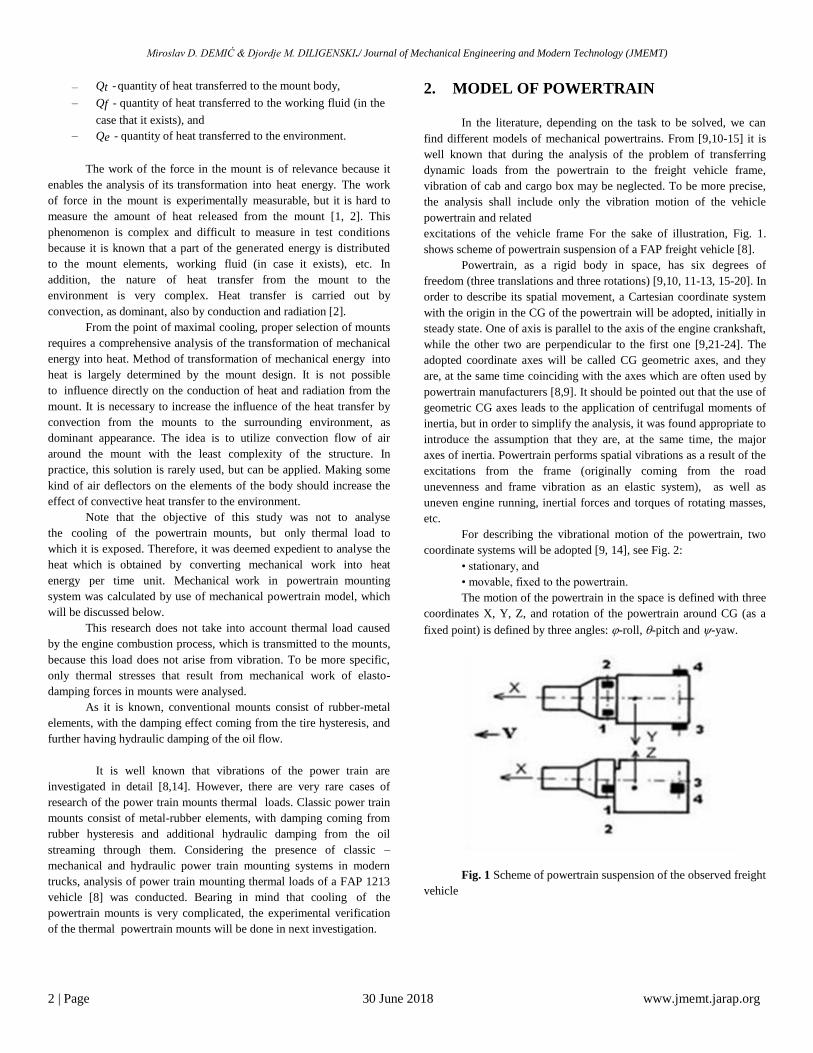
excitations of the vehicle frame For the sake of illustration, Fig. 1.
shows scheme of powertrain suspension of a FAP freight vehicle [8].
Powertrain, as a rigid body in space, has six degrees of
freedom (three translations and three rotations) [9,10, 11-13, 15-20]. In
order to describe its spatial movement, a Cartesian coordinate system
with the origin in the CG of the powertrain will be adopted, initially in
steady state. One of axis is parallel to the axis of the engine crankshaft,
while the other two are perpendicular to the first one [9,21-24]. The
adopted coordinate axes will be called CG geometric axes, and they
are, at the same time coinciding with the axes which are often used by
powertrain manufacturers [8,9]. It should be pointed out that the use of
geometric CG axes leads to the application of centrifugal moments of
inertia, but in order to simplify the analysis, it was found appropriate to
introduce the assumption that they are, at the same time, the major
axes of inertia. Powertrain performs spatial vibrations as a result of the
excitations from the frame (originally coming from the road
unevenness and frame vibration as an elastic system), as well as
uneven engine running, inertial forces and torques of rotating masses,
etc.
For describing the vibrational motion of the powertrain, two
coordinate systems will be adopted [9, 14], see Fig. 2:
• stationary, and
• movable, fixed to the powertrain.
The motion of the powertrain in the space is defined with three
coordinates X, Y, Z, and rotation of the powertrain around CG (as a
fixed point) is defined by three angles: -roll, -pitch and -yaw.
Fig. 1 Scheme of powertrain suspension of the observed freight
vehicle

Miroslav D. DEMIĆ & Djordje M. DILIGENSKI./ Journal of Mechanical Engineering and Modern Technology (JMEMT)
3 | Page 30 June 2018 www.jmemt.jarap.org
Fig. 2 Coordinate systems introduced to describe motion of the
powertrain
Newton-Euler equations are applied to describe spatial motion
of the powertrain [11].
..
C iM X X (2)
..
C iM Y Y (3)
..
C iM Z Z (4)
𝐼𝑢𝜔 𝑢 − 𝐼𝑢𝑣𝜔 𝑣 − 𝐼𝑢𝑤 𝜔 𝑤 + 𝐼𝑤𝜔𝑤 − 𝐼𝑢𝑤 𝜔𝑢 − 𝐼𝑣𝑤𝜔𝑣 𝜔𝑣 −
𝐼𝑣𝜔𝑣 − 𝐼𝑢𝑣𝜔𝑢 − 𝐼𝑣𝑤𝜔𝑤 𝜔𝑤 = 𝑀𝑢𝐹𝑖 (5)
𝐼𝑣𝜔 𝑣 − 𝐼𝑢𝑣𝜔 𝑢 − 𝐼𝑢𝑤 𝜔 𝑤 + 𝐼𝑢𝜔𝑢 − 𝐼𝑢𝑣𝜔𝑣 − 𝐼𝑢𝑤 𝜔𝑣 𝜔𝑤 −
𝐼𝑤𝜔𝑤 − 𝐼𝑢𝑣𝜔𝑢 − 𝐼𝑣𝑤𝜔𝑣 𝜔𝑢 = 𝑀𝑣𝐹𝑖 (6)
𝐼𝑤𝜔 𝑤 − 𝐼𝑢𝑣𝜔 𝑢 − 𝐼𝑣𝑤𝜔 𝑣 + 𝐼𝑣𝜔𝑣 − 𝐼𝑢𝑣𝜔𝑢 − 𝐼𝑣𝑤𝜔𝑤 𝜔𝑢 −
𝐼𝑢𝜔𝑢 − 𝐼𝑢𝑣𝜔𝑣 − 𝐼𝑢𝑣𝜔𝑤 𝜔𝑣 = 𝑀𝑤𝐹𝑖 (7)
where:
M - powertrain mass,
– 𝑋 𝐶 , 𝑌 𝐶 , 𝑍𝐶 –projections of powertrain accelerations on axes
of the moving coordinate systems,
– 𝑋𝑖 , 𝑌𝑖 , 𝑍𝑖 – projection of excitation forces and reactions of
respective powertrain mounts,
– Iu, Iv, Iw, Iuv, Iuw, Ivw – moments of inertia for the respective
coordinate axes,
– 𝜔𝑢 , 𝜔𝑣 , 𝜔𝑤 , 𝜔 𝑢 , 𝜔 𝑣 ,𝜔 𝑤 -the angular velocities and
accelerations for axes u, v and w,
– Mu , Mv, Mw – projections of torques of the excitations,
engine torque, and mounts of the powertrain for axes u, v
and w.
For the sake of simplification, it will be assumed that the
angular motions of the powertrain are small [14] what may enable the
application of the relations [9, 11, 18, 21-23]:
𝜔𝑢 = 𝜑 𝜔𝑣 = 𝜃 𝜔𝑤 = 𝜓 In order to calculate forces in the mounts, it is necessary to
define their deformations and deformation velocities. Bearing in mind
the adopted coordinate systems, motion of any point on the
powertrain is given in the equation in a matrix form [9-11]:
r=rC+LrA (8)
where:
𝑟𝐶 = 𝑋𝑌𝑍 (9)
𝑟𝐴 =
𝑎𝑖
𝑏𝑖
𝑐𝑖
(10)
𝐿 = 𝑐2𝑐3−𝑐2𝑠3
𝑠2
𝑠1𝑠2𝑐3−𝑠1𝑠2𝑠3−𝑠1𝑐2
𝑠1𝑠3 − 𝑐1𝑠2𝑐3
𝑐1𝑠2𝑠3𝑐1𝑐2
(11)
In the expression (11) s and c are cosine and sinus of the
respective angles, respectively.
For small angles the following expression can be written:
𝐿 = 1
−𝜓𝜃
𝜓1
−𝜑 −𝜃𝜑1
(12)
Similarly, and bearing in mind the low vibration of a vehicle,
the expression can be written:
r0=rc0+L0rB (13)
𝑟𝑐0 =
𝑋0
𝑌0
𝑍0
(14)
𝑟𝐵 =
𝑎𝐵𝑖
𝑏𝐵𝑖
𝑐𝐵𝑖
(15)
𝐿0 =
1−𝜓0
𝜃0
𝜓0
1−𝜑0
−𝜃0
𝜑0
1
(16)
where XO, YO and ZO - coordinates relative to the origin of the movable
coordinate system of the vehicle frame.
Since the dimensions of the mounts are small relative to the
powertrain, the following can be written:

Miroslav D. DEMIĆ & Djordje M. DILIGENSKI./ Journal of Mechanical Engineering and Modern Technology (JMEMT)
4 | Page 30 June 2018 www.jmemt.jarap.org
𝑟𝐴 ≈ 𝑟𝐵 → 𝑟𝑖 =
𝑎𝑖
𝑏𝑖
𝑐𝑖
(17)
Deformation of the i-th mount is defined by the following
matrix equation [9, 11]:
∆𝑖= 𝑟 − 𝑟0 = 𝑟𝑐 − 𝑟𝑐0 + 𝐿 − 𝐿0 𝑟𝑖 (18)
Substituting the corresponding expressions and rearranging
leads to the expressions:
ΔX𝑖 = 𝑋 − 𝑋0 + 𝑏𝑖 𝜓 − 𝜓0 − 𝑐𝑖 𝜃 − 𝜃0 (19)
ΔY𝑖 = 𝑌 − 𝑌0 + 𝑎𝑖 𝜓 − 𝜓0 + 𝑐𝑖 − 0 (20)
ΔZ𝑖 = 𝑍 − 𝑍0 − 𝑎𝑖 − 0 − 𝑏𝑖 − 0 (21)
Mount deformation velocities can be obtained by
differentiating the previous expressions:
Δ𝑋 𝑖 = 𝑋 − 𝑋 0 + 𝑏𝑖 𝜓 − 𝜓 0 − 𝑐𝑖 𝜃 − 𝜃 0 (22)
Δ𝑌 𝑖 = 𝑌 − 𝑌 0 + 𝑎𝑖 𝜓 − 𝜓 0 + 𝑐𝑖 𝜑 − 𝜑 0 (23)
Δ𝑍 𝑖 = 𝑍 − 𝑍 0 − 𝑎𝑖 𝜃 − 𝜃 0 − 𝑏𝑖 𝜑 − 𝜑 0 (24)
In the literature [19, 20] there are many mathematical models
of powertrain mounts, which are essentially more or less complicated.
Bearing in mind the objective of this study was a comparative
analysis of thermal loads in mounts, it was estimated to be acceptable
to apply more simplified expressions for approximation of forces in
the mounts.
Forces in elastic mounts are assumed in the form [9]:
𝐹𝑐𝑖 = 𝑐𝑖1Δ𝑖 + 𝑐𝑖2∆2 + 𝑐𝑖3∆
3 (25)
where:
- ci, ci1, ci2 and ci3 – stiffness coefficients, and
- i – relative deformation of the mount.
Damping forces in the mounts are assumed in the form [9]:
𝐹𝑎𝑖 = 𝑘𝑖1Δ + 𝑘𝑖2Δ2 𝑠𝑖𝑔𝑛 Δ (26)
where:
- ki1, ki2 –damping coefficients,
- ∆ - relative velocity of the mount deformation, and
- sign - respective mathematical function.
Powertrain vibrations also depend on the unbalance of the
running engine (torques and inertial forces).
In the specific case of a four-stroke four-cylinder in-line
diesel engine was used with a crankshaft whose kranks lie in the same
plane (the angle 180). Forces occur in the reciprocating mechanisms
[24] that drive the piston (gas forces and inertial forces of the piston
group), and centrifugal and tangential forces acting on the movable
bearing of the crank shaft knee. When balancing the inertial forces of
the piston group mass (in the ideal case, if a force is developed into
Fourier series), the inertial forces of the second and higher orders stay
unbalanced. It is noted that in case when there are differences in the
masses of the piston groups for each cylinder, there are also
unbalanced forces of the first order (in this considered case, the
masses have been equal to each other).
Assuming that harmonics of a higher order can be ignored,
the unbalanced inertial force of the observed engine can be expressed
in the form [14, 24]:
Fin=4mr 2 cos 2t (27)
where:
- mr – reduced mass of the piston group,
- r – radius of the crankshaft crank,
- - angular velocity of the engine crankshaft,
- - crankshaft radius and connecting rod ratio, and
- t – time.
Using basic knowledge of the vector theory and postulates of
statics, and taking into account Figs 2 and 3, the torque resulting from
the inertial force is defined by the equation (8) [9]:
𝑀𝐹𝑖𝑛 =
𝑢0 𝑎𝐸
−𝐹𝑖𝑛𝑠𝑖𝑛𝛾 𝑣0 𝑏𝐸
𝛾
𝑤0 𝑐𝐸
𝐹𝑖𝑛𝑐𝑜𝑠𝛾 (28)
wherein the expressions in (9) are harmonized with the Fig. 3.
Centrifugal force is partially balanced the counter-weights, or
by use of other methods, of which there will be no more to say, but
readers are advised to see [24].
Tangential force causes engine torque, which, due to its
variation has a variable value (unevenness is partially reduced by the
engine flywheel) [24].
In the absence of precise information, it will be assumed that
the torque acting on the powertrain can be described by expression [9]:
M=-Mei0im (0.95+0.1rnd) (29)
where:
- Me – engine torque,
- i0 – driving axle ratio,
- rnd – random numbers uniformly distributed in the interval
[0,1].
The vibration of powertrain impacts the vibration of the
vehicle frame, which is of random nature [9,14]. Bearing in mind that

Miroslav D. DEMIĆ & Djordje M. DILIGENSKI./ Journal of Mechanical Engineering and Modern Technology (JMEMT)
5 | Page 30 June 2018 www.jmemt.jarap.org
the complexity of the vehicle spatial model exceeds the needs of this
study, it is estimated to be appropriate in this specific case not to use
the frame vibration excitations based on the vehicle model, but to use
already adopted broadband excitation functions in the following form:
excitation = max (rnd- 0.5) (30)
where:
– max = 0.01 m, rad
– rnd- has the same meaning as mentioned in description of
the engine torque.
Projections of the generalized forces include all the
components of forces and torques of the corresponding mount in the
direction of the observed axes (for mounts 1 to 4), the engine inertial
forces and torques and unbalanced inertial forces, as well as the active
suspension force which, does not have the corresponding torque due to
the assumption that it acts in the powertrain C.G.
Bearing in mind the expressions (1-27), differential equations
of motion of the powertrain can be written in the form:
𝑀𝑢 = 𝑋𝑖 (31)
𝐼𝑢𝜑 = 𝑀𝐹𝑢 (32)
𝑀𝑣 = 𝑌𝑖 (33)
𝐼𝑣𝜃 = 𝑀𝐹𝑣 (34)
𝑀𝑤 = 𝑍𝑖 (35)
𝐼𝑤𝜓 = 𝑀𝐹𝑤 (36)
Fig. 3 Inertial force and engine torque
where:
Fin – resulting inertial force of piston group,
Me – engine torque,
E – acting point of the resulting force and its coordinates
related to the moving coordinate system,
- engine inclination (in the observed case 0).
3. THERMAL LOAD OF MOUNTING
SYSTEM
Due to the relative motion of sprung and unsprung masses,
mechanical work is being done in mounts, which is equivalent to the
amount of produced heat, Q [2]. Mechanical work (the amount of heat)
is defined by the expression [2-7]:
0 0
s T
m rel m relA F t dz F t z dt , (37)
where:
• mF t - is elasto-damping force in the mount,
• relz – is deformation of the mount, eqns (19 - 21),
• relz - relative velocity of deformation (time derivatives of
displacements) given by eqns (22-24) and
• t – is time.
Mechanical power, P t , that is equivalent to heat flux, is
the first derivative of mechanical work with respect to time:
( )dA
P tdt
(38)
Average power, avP , is given by expression [10]:
0
1( )
T
av
AP P t dt
T T , (39)
where T is the monitoring period. Average power turns into heat, with
dominant convection [10]:
P S , (40)
where:
• - is heat transfer coefficient,
• S - convection area and
• - is temperature difference between the mounts and
surrounding air.
As already noted, the analysis of heat transfer from the
mount has not been carried out in the paper, because the values of i
and iS are not known, and it requires very extensive experimental
studies to determine these values, which will certainly be the subject of
special attention in the future.

Miroslav D. DEMIĆ & Djordje M. DILIGENSKI./ Journal of Mechanical Engineering and Modern Technology (JMEMT)
6 | Page 30 June 2018 www.jmemt.jarap.org
Since all four power train unit mounts had the same
characteristics, the analysis of collective thermal loads was conducted.
4. NUMERICAL SIMULATION AND
ANALYSIS OF RESULTS
On the basis of the expressions (1-40), it can be seen that the
differential equations describing the spatial vibration of the vehicle
powertrain are non-linear and should be solved numerically, by use of
the method Runge-Kutta, and by use of a software developed by the
authors, in Pascal. The integration was carried out with the time
increment of 0.0001 s, in 524288 points. This enabled reliable analysis
in the domain 0.019-5000 Hz [25]. It is obvious that the domain is
much broader than range of excitations from the running engine and
the entire vehicle powertrain. Integration of differential equations is
carried out in case of using conventional and hydraulic mounts.
The parameters of the observed vehicle and its powertrain
given in Tab. 1, and the coordinates of the connection points (mounts)
in Tab. 2.
Table 1. Characteristic parameters of the vehicle FAP 1213 and its
powertrain
Maximal engine power, kW 100
Maximal engine speed, min-1 2600
Maximal engine torque, Nm 428
Engine speed at max. engine torque, min-1 1300
Vehicle mass, kg 12000
Powertrain mass, kg 1680
Moments of inertia Ix/Iy/Iz, kgm2 85/35/72
Driving axle gear ratio, - 3.83
Transmission ratio in direct gear, - 1
Table 2. Engine mounts coordinates
Mount
position
a, m b, m c, m
Mount 1 0.5 0.4 0.1
Mount 2 0.5 -0.4 0.1
Mount 3 -0.5 0.4 0.1
Mount 4 -0.5 -0.4 0.1
Mechanical and hydraulic mounts have identical stiffness in
the direction of the axes X, Y and Z, which are determined by the tests
performed in FAP [8], as shown in Table 3.
Table 3. Stiffness of the applied conventional and hydraulic mounts
ci1, N/m
ci2, N/m2 ci3, N/m3
X 1200000 250000 60000
Y 1200000 250000 60000
Z 1200000 250000 60000
In the absence of accurate data, damping characteristics of the
mounts are approximately defined on the basis of the support stiffness
and mass carried by those [11], and are given in Tab. 4.
Table 4. Assumed damping characteristics of the mounts
ki1 (mechanical/
hydraulic), Ns/m
ki2 (mechanical/
hydraulic), Ns2/m2
X 620/62000 1/100
Y 620/62000 1/100
Z 620/62000 1/100
In this paper it is assumed that the frame has six identical
excitations in the time domain (eq. 30). For the illustration, vertical
vibration excitations of the powertrain, derived from the frame
vibration are shown in Fig. 4. It is obvious that the excitations are very
dynamic, and so large thermal load of the powertrain mounts should be
expected.
.
Fig. 4 Illustration of the frame excitation

Miroslav D. DEMIĆ & Djordje M. DILIGENSKI./ Journal of Mechanical Engineering and Modern Technology (JMEMT)
7 | Page 30 June 2018 www.jmemt.jarap.org
Results of the dynamic simulation are shown in the time
domain. To illustrate, Fig. 4 gives the variation of displacements in
case of use of hydraulic mounts. Analysis of the data concerning
classical and hydraulic mounts, partially shown in Fig. 5, in the time
domain, shows that the type of the applied mounts affects the character
and the amplitude of the monitored displacement of the powertrain.
Fig. 5 Powertrain displacements in case of hydraulic mounts
Summarized thermal loads (for all forces and torques
components and for all four mounts) are calculated using the Eqs (2-
40) and the results are shown in Figs 6 and 7, wherein the values in
Fig. 6 for the amount of heat are given in the log scale.
Fig. 6 Quantity of heat (mechanical work) depending on the type of
mount
Fig. 7 Heat flux depending on the type of mounts
Table 5. Statistical data on heat flux
Mounts Min,
W
Max, W Mean
value,
W
Effective
value,
W
Classical 2.494
102
2.973
108
2.271
107
3.
438 107
Hydraulic 2.570
102
1347
1010
1.038
109
1.
609 109
The analysis of Fig. 6 shows that mechanical mounts suffer from
approximately 45 times lower thermal loads then the hydraulic (for
52 s, classical about 1.19x10⁹ J, and hydraulic about 53.69x10⁹ J).
This is understandable bearing in mind that hydraulic mounts, in
addition to hysteresis in the rubber, have the additional fluid flow
within the mount. Fig. 6 shows that the amount of heat increases with
time and that in the absence of cooling, they would experience a
degradation of the shape and characteristics.
Fig. 7 shows how the heat flux depends on the time. It is obvious that
it changes stochastically over time, so for the sake of the analysis, it is
necessary to calculate some characteristic statistical values given in
Tab. 5 [25,26].
Analysis of the data from Tab. 5 shows that the heat flux is much
higher in hydraulic, that in the conventional suspension of powertrain.
This indicates a greater possibility of degradation of characteristics of
hydraulic mounts compared to the classical. Therefore they are bigger
in size than the classical. It should be pointed out that such high
values of thermal flow are a result of rigorous excitations of vehicle
frame that were used in the simulation. In practice, they are
significantly milder, and consequently the real thermal load of the

Miroslav D. DEMIĆ & Djordje M. DILIGENSKI./ Journal of Mechanical Engineering and Modern Technology (JMEMT)
8 | Page 30 June 2018 www.jmemt.jarap.org
powertrain mounts. However, the research is carried out to determine
the ratio of the thermal load of classic and hydraulic supports, with by
use of models, so the obtained results can be adopted only as an
orientation, which is acceptable in the initial design phase of the
truck. It should be mentioned that hydraulic mounts have significantly
better performance when vibrations of the powertrain are in question
[9].
5. CONCLUSIONS
The research shows that mechanical models can perform analyses of
the impact of powertrain supports features on their thermal loads.
Analyses showed that the hydraulic supports are significantly more
exposed to heat load than the conventional. Bearing in mind the
thermal loads, as well as a more complex structure, the less frequent
application of hydraulic supports at the freight vehicles powertrain is
expected. In order to verify the obtained results the experimental
research should be carried out in the future.
Based on the research results the following conclusions can made:
The proposed model of powertrain can be used for the simulation of
thermal load of freight vehicle powertrain mounts,
The hydraulic mounts of powertrain are subjected to a significantly
greater thermal load than the conventional, and
Bearing in mind the extent of the existing thermal loads, as well as a
more complex design, the application of hydraulic powertrain mounts
is understandably less frequent in freight vehicles powertrain
suspension.
Nomenclature
z- vertical vibration, [m]
A – work, [ J]
Iu, Iv, Iw - moment of inertia, [ kgm2]
f – frequency, [Hz],
t – time, [s],
Q - quantity of heat, [J ]
Fm -force in the shock absorber, [N]
Greek symbols:
- roll, [rad]
- pitch, [rad]
ψ- yaw of the powertrain, [rad]
x – reference for x-axis, y – reference
for y-axis, and z – reference for z-axis
REFERENCES
[1] Demić, M., Diligenski, Đ. (2016) Numerical simulation of shock
absorbers heat load for semi-active suspension system, Therm
Sci, 20, 5: 1725-1739, doi 10.2298/TSCI150624005D
[2] Mitschke, M. (1997) Kraftfahrzeugkonstruktion, Teil D. TU
Braunschweig, Forlesung, Germany,
[3] Atkins, P. (2010) The Laws of Thermodynamics (A Very Short
Introduction), Oxford, UK
[4] Bojić, M. (2011) Thermodynamics (in Serbian). University of
Kragujevac, Mechanical Engineering Faculty
[5] Ilić, G., et al (1996) Thermodynamics II, Basics of heat transfer
(in Serbian), University of Niš, Mechanical Engineering Faculty
[6] Moran, M.J., et al (2010) Fundamentals of Engineering
Thermodynamics, John Wiley and Sons
[7] Fermi, E. (2011) Thermodynamics, Dover Books on Physics
[8] FAP Informations (2017) (in Serbian), Priboj, Serbia
[9] Demić M. (1990) A contribution to the optimization of the
position and the characteristics of passenger cars powertrain
mounts, Int J of Vehicle Des, 1: 87-103
[10] Mitschke M. (1972) Dynamik der Kraftfahrzeuge (in German),
Springer Verlag, Germany
[11] Pars, L. (1971) A Treatise on Analytic Dynamics, Heinemann,
London, UK
[12] Rotenberg R. (1972) Motor Vehicle Suspension (in Russian),
Mashinostroenie, Moscow, Russia
[13] Simić D. (1988) Motor Vehicle Dynamics (in Serbian), Naučna
knjiga, Belgrade, Serbia
[14] Simić, D., Demić, M. (1992) Mounting of the power train
(monograph), MVM, Kragujevac, Serbia
[15] Shanguan, W.B., et al (2016) Design method of automotive
powertrain mounting system based on vibration and noise
limitations of vehicle level, Mech Syst Signal Pr, 677-695
[16] Demić M. (1997) Identification of Vibration Parameters for
Motor Vehicles, Vehicle Syst Dyn, 27: 65-88
[17] Demić M. (1997) The Optimization of Vibratory Systems of
Motor Vehicles (monograph, in Serbian) – Mechanical
Engineering Faculty, Kragujevac, Serbia
[18] Frolov K.V., Furman F.A., (1980) Applied theory of vibration
protection systems (in Russian), Mashinostroenie, Moscow,
Russia
[19] Ravi, K. et al (2016) Study of Engine Mountings: A Review,
The International Journal of Science & Technoledge, 4 10: 38-46
[20] Kadam V.V., Kulkarni N. (2016) Modelling & Analysis of
Engine Mount System for Vibration Reduction, International
Journal of Latest Trends in Engineering and Technology, 7 3:
53-60
[21] Genta A. (2003) Motor Vehicle Dynamics, Politecnika di
Torino, Torino, Italy
[22] Gillespie T.D. (1992) Fundamentals of Vehicle Dynamics, SAE
[23] Miliken W., Miliken D. (19959 Race Car Dynamics, SAE
[24] Mahalec, I., et al. (2015) Z., Engine Constructions (in Croatian),
FSB Zagreb, Croatia
[25] Bendat J.S., Piersol A.G. (2000) Random Data-Analysis and
measurement procedures, John Wiley and Sons Inc., London,
UK
[26] Demić, M., (2003) ANALSIGDEM: Software for signal
analysis. Available online at
www.ptt.yu/korisnici/i/m/imizm034/