a constraint-aided conceptual design environment for autodesk
TRANSCRIPT

A Constraint-Aided Conceptual Design Environment forAutodesk Inventor ?
Alan Holland, Barry O’Callaghan, and Barry O’Sullivan
Cork Constraint Computation CentreDepartment of Computer Science, University College Cork, Ireland{a.holland|b.ocallaghan|b.osullivan }@4c.ucc.ie
Abstract. Engineering conceptual design can be defined as that phase of theproduct development process during which the designer takes a specification fora product to be designed and generates many broad solutions for it. It is wellrecognized that few computational tools exist that are capable of supporting thedesigner work through the conceptual phase of design. However, significant re-cent developments have been made in solid modeling and 3D computer-aideddesign. The use of such tools has become a critical element in the more sophisti-cated product development processes to be found in modern industry. This paperpresents a prototype constraint-based computer-aided design (CAD) technologythat can be used to support designers working in the early stages of design. Thetechnology has been developed as an add-in application for Autodesk Inventor, a3D solid-modeling environment. The add-in has, at its core, a constraint filteringsystem based on generalised arc-consistency processing and backtrack search.We present our current prototype and a detailed demonstration of its functional-ity. Finally, we describe our current work on a number of additional features forthe next prototype, which will be deployed in an industrial context.
1 IntroductionEngineering conceptual design can be regarded as that phase of the engineering designprocess during which the designer takes a specification for a product to be designedand generates many broad solutions for it. Each of these broad solutions is generallyreferred to as ascheme[7]. It is generally accepted that conceptual design is one of themost critical phases of the product development process. It has been reported that morethan 75% of a product’s total cost is dictated by decisions made during the conceptualphase of design and that poor conceptual design can never be compensated for at thedetailed design stage [10].
To support interactive conceptual design a number of issues must be considered.Firstly, the conceptual design process is initiated by a statement describing the desiredproperties of the required product. This statement may not be complete and may bemodified during design. Secondly, conceptual design is a process in which synthesis ofa scheme is a fundamental activity. However, the designer should have the freedom to
? This research is funded by Enterprise Ireland, through their Research Innovation Fund (GrantNumber RIF-2001-317). The software used for the project, Autodesk Inventor, has been spon-sored by cadcoevolution.com, an Irish CAD provider.

approach the process in anyway he wishes. Thirdly, in so far as it is possible, design-ers should be alerted to any inconsistencies that exist in their designs. Designers mayseek explanations for such inconsistencies, or justifications for why certain options arenot available to them. Alternatively, designers may wish to be given an explanation de-tailing how a particular scheme has come about. Fourthly, automated evaluation andcomparison of multiple schemes, throughout the design process, is necessary to focusthe designer on promising alternatives. Finally, designers prefer to use tools which arefamiliar to them and, therefore, any additional tools that a designer is expected to usemust have a “look-and-feel” similar to those they already use. It was these considera-tions that set the agenda for the work reported here.
This paper presents a prototype constraint-based computer-aided design (CAD)technology that can be used to support designers working in the early stages of de-sign. We present the current status of our prototype and a detailed demonstration of itsfunctionality. We report on some industrial experiences and describe our current workon a number of additional features for the next prototype, which will be deployed inan industrial context. The CAD technology has, at its core, a constraint filtering systembased on generalised arc-consistency processing [3] and backtrack search. Using thetechnology, the designer can be assisted in developing and evaluating a set of schemeswhich satisfy the various constraints that are imposed on the design. Explanations andjustifications can be generated to aid the designer’s understanding of the state of the de-sign problem. Arbitrary constraints can be asserted or retracted by the designer whichpermits the incorporation of new requirements into the design specification and give thedesigner freedom to approach the process as he wishes.
The remainder of the paper is organized as follows. Section 2 presents an overviewof the relevant literature. Section 3 presents an overview of the theory of conceptualdesign upon which the work presented in this paper is based. Section 4 presents anoverview of the current prototype of our CAD technology for supporting conceptualdesign. Section 5 outlines our plans for future development and deployment. In Sec-tion 6 a number of concluding remarks are made.
2 Related ResearchIn the design literature three phases of design are generally identified: conceptual de-sign, embodiment design and detailed design [16]. During conceptual design the de-signer searches for a set of broad solutions to a design problem, each of which satisfiesthe fundamental requirements of the desired product. The embodiment phase of de-sign is traditionally regarded as the phase during which an initial physical design isdeveloped. This initial physical design involves the determination of component ar-rangements, initial forms and other part characteristics. The detailed phase of design istraditionally regarded as the phase during which the final physical design is developed.
Constraint-based applications for design have been more commonly applied to thepost-conceptual phases of design [11, 12, 21]. The use of constraint processing tech-niques for supporting configuration design has also been widely reported in the litera-ture [13, 19].
Modern approaches to product development, such as Concurrent Engineering [4],attempt to maximize the degree to which design activities are performed in parallel.Researchers in the constraint processing community have developed constraint-based

technologies that support integrated approaches to product development [5]. Constraint-based approaches to managing conflict in collaborative design systems have also beenreported [2, 9, 11]. Using constraints to co-ordinate distributed agents in engineeringdesign has also been reported [17].
Constraint-based approaches to supporting conceptual design have been reportedin the literature for quite a number of years [8, 18, 20]. However, most of this researchdoes not address the synthesis problem; the vast majority has focused on constraintpropagation and consistency management relating to more numerical design decisions.For example, “Concept Modeler” is based on a set of graph processing algorithms thatuse bipartite matching and strong component identification for solving systems of equa-tions [20]. The Concept Modeler system allows the designer to construct models of aproduct using iconic abstractions of machine elements.
Based on the earlier work on Concept Modeler, a system called “Design Sheet” hasbeen developed [18]. This system is essentially an environment for facilitating flexibletrade-off studies during conceptual design. It integrates constraint management tech-niques, symbolic mathematics and robust equation solving capabilities with a flexibleenvironment for developing models and specifying tradeoff studies. The Design Sheetsystem permits a designer to build a model of a design by entering a set of algebraicconstraints. The designer can then use Design Sheet to change the set of independentvariables in the algebraic model and perform trade-off studies, optimization and sensi-tivity analysis.
While not a constraint-based system, the Conceptual Understanding and Prototyp-ing Environment (CUP) is an approach to supporting conceptual design that unites ideasfrom traditional mechanical design with 3D layouts and knowledge engineering [1]. Ofall of the systems reviewed here, CUP is most similar to the approach that we haveadopted. However, our technology is entirely constraint-based which gives us the op-portunity to exploit the semantics of constraints and use inference as a core techniquefor navigating the design search space, providing explanations and an immediate declar-ative approach to modeling the evolving schemes that the designer wishes to explore.
3 The ApproachIn this section we will give an overview of the approach to conceptual design that hasmotivated the design of the CAD system which we will present in Section 4. The modelof conceptual design adopted here is based on the well accepted observation that duringthis phase of design a designer works from an informal set of requirements that theproduct must satisfy and generates alternative schemes which satisfy them.
Central to the process of scheme generation is an understanding of function and howit can be provided. The process involves the development of a functional decompositionwhich provides the basis for a realization of physical elements that form a scheme.In addition to determining which physical elements comprise a scheme, the relationsbetween them must also be specified to a sufficient extent to permit the evaluation andcomparison of alternative schemes.
In the remainder of this section a brief overview of some of the most importantaspects of our approach to conceptual design will be presented. For a more completediscussion of the theory the reader is encouraged to refer to the more detailed literatureavailable [14, 15].

3.1 The Design Specification
The conceptual design process is initiated by the recognition of a need or customerrequirement. This need is analyzed and translated into a statement which defines thefunctionality that the product should provide (referred to asfunctional requirements)and thephysicalrequirements that the product must satisfy. This statement is known asadesign specification.
A design specification will contain both abstract functional requirements as wellas concrete physical requirements. The functional requirements define the “purpose”of the desired product at as high a level of abstraction as possible. In addition, twoclasses of physical requirement can be identified: product requirements and life-cyclerequirements. These requirements can be eithercategorical requirementsthat defineconstraints between attributes of the product or its life-cycle, or they can bepreferencesrelated to subsets of these attributes.
Essentially, the design specification comprises a set of constraints which must besatisfied and a set of objective functions with respect to which the desired product mustbe Pareto optimal [14].
3.2 Conceptual Design Knowledge
In order to successfully synthesize alternative schemes that meet the requirements de-fined in the design specification, the designer needs considerable knowledge of howfunction can be provided by physical means. This knowledge exists in a variety offorms; a designer may not only know of particular components, sub-assemblies andtechnologies that can provide particular functionality, but may be aware of abstractconcepts which could also be used. For example, a designer may know that an elec-tric light-bulb can generate heat or, alternatively, that heat can be generated by rubbingtwo surfaces together. The latter concept is more abstract that the former. In order toeffectively support the designer during conceptual design, these alternative types of de-sign knowledge need to be modeled in a formal way. However, a CAD system whichsupports conceptual design must also be capable of dealing with the designer’s “off-the-cuff” ideas and store them for future use if they are deemed useful.
Reasoning about FunctionWe employ afunction-means mapapproach to cataloginghow function can be provided by means [6, 14]. In a function-means map two differenttypes of means can be identified:design principlesanddesign entities. A design prin-ciple is a means which is defined in terms of a set of functions that must be providedin order to provide some higher-level functionality. Design principles are abstractionsof known approaches to providing function. By utilizing a design principle the designercan decompose higher-level functions without committing to a physical solution tooearly in the design process. The functions that are required by a design principle collec-tively replace the function being embodied by that principle. The functions which definea design principle will, generally, have a number ofcontext relationsdefined betweenthem. These context relations describe how the parts in the scheme, which provide thesefunctions, should be configured so that the design principle is used in a valid way. Forexample, in Figure 1,principle 1comprises two functions,f1 andf2, between which acontext relationr1 is defined.

Note that a design principle is not just a model of a known physical design solution,but is an abstraction which can be used to encourage creativity and analogical reason-ing during design. An example of this was presented above when defining an abstractconcept for generating heat by rubbing two surfaces together.
A design entity, on the other hand, is a physical, tangible means for providing func-tion such as a component or sub-assembly. A design entity is defined by a set of param-eters and the constraints that exist between these parameters. For example, an electronicresistor would be modeled as a design entity which is defined by three parameters, re-sistance, voltage and current, between which Ohm’s Law would hold.
Embodiment of Function As the designer develops a scheme for a product every func-tion in the scheme is embodied by a means. Each means that is available to the designerhas an associatedset of behaviors. Eachbehavioris defined as a set of functions that themeans can be used to provide simultaneously. Each behavior associated with a designprinciple will contain only one function to reflect the fact that it is used to decompose asingle function. However, a behavior associated with a design entity may contain manyfunctions to reflect the fact the there are many combinations of functions that the entitycan provide at the same time. For example, the bulb design entity mentioned earlier maybe able to fulfill the functionsprovide lightandgenerate heatsimultaneously. However,when a design entity is incorporated into a scheme it is not necessary that every functionin this behavior be used in the scheme.
Fig. 1: An example of scheme configuration.

3.3 Scheme Configuration using Interfaces
Generally, the first means that a designer will select will be a design principle. Thisdesign principle will substitute the required (parent) functionality with a set of childfunctions. Ultimately the designer will embody all leaf-node functions in the functionaldecomposition with design entities. During this embodiment process, the context rela-tions from the design principles used in the scheme will be used as a basis for definingthe interfaces (constraints) between the design entities used in the scheme.
For example, in Figure 1 an example scheme structure is illustrated. The top-levelfunction in this scheme isf0. This function is embodied using a design principle calledprinciple 1. This design principle introduces two functions,f1 and f2 to replace thefunctionf0. A context relation,r1, is specified between these functions. The functionf1is embodied by a design principle,principle 2, which introduces two further functions,f3 andf4 into the scheme. A context relation,r2, is specified between these functions.The functionf3 is embodied with the design entityent 1, the functionf4 is embodiedwith the design entityent 2and the functionf2 is embodied with the design entityent3. However, between which design entities should the context relationsr1 and r2 beconsidered?
The context relationr2 must exist between the entities that derive from the functionsf3 andf4. The design entitiesent 1andent 2are used to embody these functions. Thus,the context relationr2 must be considered between these entities. Since, the designentitiesent 1andent 2are the means used to provide the functionsf3 and f4, theseentities can be regarded as beingdirectlyused to provide these functions.
The context relationr1 is a little more complex. This context relation must existbetween the entities that derive from the functionsf1 and f2. The design entityent 3is used to embody the functionf2. Thus this entity can be regarded as beingdirectlyused for the functionf2. The functionf1 is provided by the design principleprinciple 2,whose child functions are in turn embodied by the design entitiesent 1andent 2. Thus,these design entities can be regarded as beingindirectly used to provide the functionf1. Therefore, the context relationr1 must be considered between the combination ofdesign entitiesent 1andent 2on the one hand, andent 3on the other hand.
The precise nature of these interfaces cannot be known with certainty until the de-signer embodies functions with design entities; this is because the link between func-tions and design entities is generally not known with certainty during the developmentof the functional decomposition for the scheme. Until the precise nature of a particu-lar interface is known, they are modeled as constraints between design entities whichcan be used to reason about the product structure; for example, interfaces may repre-sent simple spatial relationships which can inform an evaluation related to the relativeposition of parts in a product.
The types of interfaces that may be used to synthesize a product structure will bespecific to the engineering domain within which the designer is working. Indeed, theseinterfaces may also be specific to the particular company to which the designer belongsin order to ensure the configurability of the product.

4 An Overview of the Current PrototypeIn this section we present the key features of our current prototype CAD technologyfor supporting conceptual design, which we call ConCAD Expert. The technology isseamlessly integrated with Autodesk Inventor1. This particular CAD system has beenchosen for a number of reasons. In particular, as well as being one of the most popular3D solid modeling design environments, Inventor has an architecture similar to mosttools of its kind, but has a very rich API through which we can integrate with the hostCAD system.
Our technology has been designed to interface to the Inventor (version 5.3) CADsystem as an add-in application that can be invoked by the designer at any point. At itscore is an interactive constraint filtering system based on generalised arc-consistency [3]and backtrack search. The system is fully interactive, monitoring the consistency ofdesigner decisions and providing feedback when an inconsistency has been detectedor the designer has requested justifications or explanations from the system. It wasdeveloped using C#, and uses the Autodesk Inventor 5.3 COM API. An XML databasehas been developed to store the parts available to the CAD system. The XML schemathat has been used, represents a part file and the various attributes of each part. We nowpresent many of the features of our prototype in the form of a “walk-through”.
Once the conceptual design tool has been invoked, the designer can use a FunctionalView panel (see left-hand side of Figure 2) to define the functionality and physicalconstraints that the desired product must satisfy.
Fig. 2: Beginning a conceptual design session using a design principle.
Once the ConCAD Expert add-in has been invoked the designer can begin to de-velop his concept by developing a functional decomposition and mapping functions
1 See:http://www.autodesk.com/inventor

onto parts which will be loaded into Inventor automatically. In Figure 2 the designerbegins to design an engine by incorporating a pre-defined design principle for an inter-nal combustion engine. The result of this action can be seen in Figure 3, where eachof the functional elements of an engine can be seen in the Functional View pane. Notethat this is an abstract description. Each of the elements in the Functional View panerelates to a design element which is represented as a function. No parts have yet beenselected at this point. However, the designer is free to select parts if desired, or canextend the functional description of each element further by incorporating additionaldesign principles into the scheme. Furthermore, the designer can define context rela-tions (constraints) between elements of the functional description, in addition to thosethat form part of the definition of the engine design principle, if desired. These willdefine how each of the elements must relate each other in the part model.
At the moment, the designer can select design principles from a predefined database,or can manually define them on-the-fly. Obviously, we would like the conceptual designsystem to store any new descriptions for use in future projects. At the moment, this mustbe done by manually including them in the database. However, in the next version ofthe system the identification and storage of design principles will be done automatically.In this way the CAD system will acquire the design principles for a particular designdomain over time.
Fig. 3: Viewing recommended means.

At any point in time the designer can view which means in the CAD database arerecommended for use in the designer’s scheme. Recommended means must not onlysatisfy the functional requirements defined in the functional decomposition, but mustalso be consistent with the physical constraints defined explicitly by the designer andimplicitly by any other means used in the scheme.
In Figure 3 the designer has asked the CAD system to recommend means for thecarburettor element in the functional decomposition. As can be seen on the middle-leftside of the figure, five alternative means have been found for this element from whichthe designer is free to choose. In this example, all means that can provide the requiredfunctionality for this element are recommended; otherwise they would have been dis-played in theOther Meansbox. A means is no longer recommended if it satisfies thefunctional constraints, but violates one or more physical constraints.
However, for the purposes of explanation lets assume that before the designer selectsone of these means he defines an additional constraint in the CAD system. An interfaceused to do this is shown in Figure 4. The designer is free to define constraints on anycharacteristic of the scheme. In this figure, the designer has defined the constraint thatensures that the mass of the means that will be used to provide the functionality of thecarburettor will have a mass that is no more than a given maximum value.
Fig. 4: Specifying additional constraints.
The consequence of this constraint is that some of the means which could havebeen used as a carburettor have been removed and placed in a list ofOther Means,which contains those means that are no longer recommended for this situation. Thisscenario is depicted in the lower left of Figure 5.
Also presented in this figure is a window showing the attributes of a particular meansselected by the designer. In this figure the designer has clicked on the recommended

part,Carb2.1.iam. Note in the attributes window that the mass of the part satisfies theconstraint that the maximum mass of the carburettor be no more than 150g.
Fig. 5: The effect of the designer’s constraint.
As the designer makes decisions and interacts with the CAD system, a CSP modeldescribing the characteristics of the desired product is being developed. Part of the con-straint model that the designer has developed at this point in our example is presentedin Figure 6.
In this figure we can, firstly, see at the top the set of constant definitions. Secondly,we can see the set of variables in our design and their corresponding domains. Finally,we have the set of constraints defined by the design specification for the product, anyadditional constraints defined by the designer or constraints added to the model whichare implied by the designer’s decisions.
To illustrate the consequences of constraint addition and domain filtering in ourprototype, Figure 7 shows the effect of adding an overall cost constraint to the model.This constraint was entered using the interface presented in Figure 4. We can see fromFigure 7 that the list of of recommended means has been reduced further through in-

Fig. 6: The CSP can be viewed at any stage during the design process.
ference, which in the prototype is based on generalized consistency processing. In thisfigure the designer has asked for an explanation for why theCarb1.0.iamis no longerrecommended by selecting it from the list. An explanation is given in Figure 8 whichspecifies the constraints with which the part is inconsistent. Explanations are currentlygenerated directly from the inference algorithm used in the prototype.
Figure 9 presents the extended CSP model of our scheme which includes the designer-specified cost constraint (shown last in the figure). Note how the domains of the moreexpensive parts were heavily reduced whereas the smaller cheaper parts such as themountwere unaffected.
As the designer develops the functional decomposition he can also select parts forproviding the necessary functionality. There is no restriction placed on the order that thedesigner develops a scheme. Figure 10 shows the CAD system interface after the de-signer has begun to select parts. The constraint model that the CAD system contains atthis point not only includes constraints on the functional decomposition and each part,but also constraints on the way parts can be configured. These interface constraints de-rived from the constraints that the designer specified while developing the functionaldecomposition for the product, as well as the various design principles that were em-ployed. As the designer develops the scheme further, inference on these constraints willassist the designer make consistent decisions on a valid configuration of these parts.
The designer does not need to fully specify the entire design at this point since thatis a detailed design task. All that is required is that the designer specify the scheme to anextent which permits it to be evaluated against the constraints in the design specificationand compared against any alternative schemes that have been developed.

Fig. 7: A constraint was added setting the total Cost below a certain threshold. The Carb1.0.iamassembly violated this constraint because it was too expensive.
Fig. 8: An explanation showing the cost constraint that the the Carb1.0.iam assembly has violated.
5 Next Steps
The CAD technology presented here is being developed for industrial deployment. Inanticipation of the release of the tool, we are currently developing the next generationof the CAD system which will have a number of additional capabilities. Some of theseare discussed below.
In the current prototype the designer either manually enters the entire functionalspecification for an artifact, or uses predefined principles. We are currently working onan approach which helps capture new design principles and modifications of existingones, and store them in the database for future use. In this way, not only will the CADsystem be capable of learning from the designer, but will also alleviate a company fromhaving to completely specify a design knowledge-base before the CAD technology isuseful. The approach we are adopting is designer-driven. The designer decides whatconstitutes a sufficiently detailed abstract description of a principle. The system facili-tates the designer by storing his concepts, whatever they may be. This feature is critical
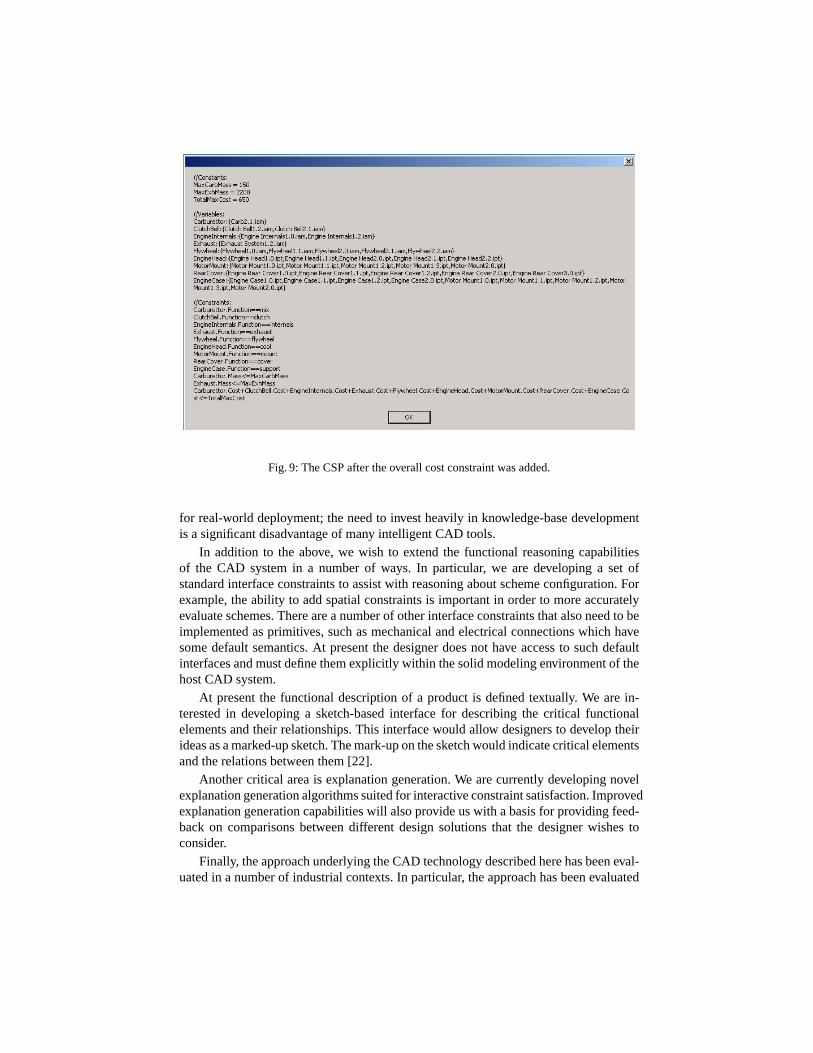
Fig. 9: The CSP after the overall cost constraint was added.
for real-world deployment; the need to invest heavily in knowledge-base developmentis a significant disadvantage of many intelligent CAD tools.
In addition to the above, we wish to extend the functional reasoning capabilitiesof the CAD system in a number of ways. In particular, we are developing a set ofstandard interface constraints to assist with reasoning about scheme configuration. Forexample, the ability to add spatial constraints is important in order to more accuratelyevaluate schemes. There are a number of other interface constraints that also need to beimplemented as primitives, such as mechanical and electrical connections which havesome default semantics. At present the designer does not have access to such defaultinterfaces and must define them explicitly within the solid modeling environment of thehost CAD system.
At present the functional description of a product is defined textually. We are in-terested in developing a sketch-based interface for describing the critical functionalelements and their relationships. This interface would allow designers to develop theirideas as a marked-up sketch. The mark-up on the sketch would indicate critical elementsand the relations between them [22].
Another critical area is explanation generation. We are currently developing novelexplanation generation algorithms suited for interactive constraint satisfaction. Improvedexplanation generation capabilities will also provide us with a basis for providing feed-back on comparisons between different design solutions that the designer wishes toconsider.
Finally, the approach underlying the CAD technology described here has been eval-uated in a number of industrial contexts. In particular, the approach has been evaluated
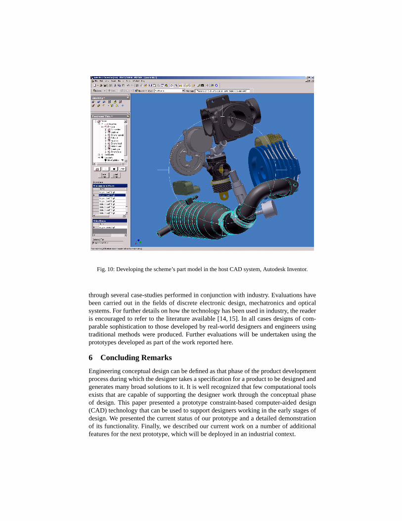
Fig. 10: Developing the scheme’s part model in the host CAD system, Autodesk Inventor.
through several case-studies performed in conjunction with industry. Evaluations havebeen carried out in the fields of discrete electronic design, mechatronics and opticalsystems. For further details on how the technology has been used in industry, the readeris encouraged to refer to the literature available [14, 15]. In all cases designs of com-parable sophistication to those developed by real-world designers and engineers usingtraditional methods were produced. Further evaluations will be undertaken using theprototypes developed as part of the work reported here.
6 Concluding Remarks
Engineering conceptual design can be defined as that phase of the product developmentprocess during which the designer takes a specification for a product to be designed andgenerates many broad solutions to it. It is well recognized that few computational toolsexists that are capable of supporting the designer work through the conceptual phaseof design. This paper presented a prototype constraint-based computer-aided design(CAD) technology that can be used to support designers working in the early stages ofdesign. We presented the current status of our prototype and a detailed demonstrationof its functionality. Finally, we described our current work on a number of additionalfeatures for the next prototype, which will be deployed in an industrial context.

References1. L. Anthony, W.C. Regli, J.E. John, and S.V. Lombeyda. CUP: A computer-aided conceptual
design environment for assembly modeling. Technical Report DU-MCS-01005, Departmentof Mathematics and Computer Science, Drexel University, June 2001.
2. D. Bahler, C. Dupont, and J. Bowen. An axiomatic approach that supports negotiated res-olution of design conflicts in Concurrent Engineering. InArtificial Intelligence in Design,pages 363–379, 1994. Kluwer Academic Press, Netherlands.
3. C. Bessiere and J.-C. Regin. Arc consistency for general constraint networks: preliminaryresults. InProceedings IJCAI’97, pages 398–404, 1997.
4. W.P. Birmingham and A. Ward. What is Concurrent Engineering?Artificial Intelligencefor Engineering Design, Analysis and Manufacturing, 9:67–68, 1995. Guest Editorial in aSpecial Issue on Concurrent Engineering.
5. J. Bowen and D. Bahler. Frames, quantification, perspectives and negotiation in constraintnetworks in life-cycle engineering.Artificial Intelligence in Engineering, 7:199–226, 1992.
6. J. Buur.A Theoretical Approach to Mechatronics Design. PhD thesis, Technical Universityof Denmark, Lyngby, 1990.
7. M.J. French.Engineering Design: The Conceptual Stage. Heinemann, London, 1971.8. M.D. Gross, S.M. Ervin, J.A. Anderson, and A. Fleisher. Constraints: Knowledge represen-
tation in design.Design Studies, 9(3):133–143, July 1988.9. D. Haroud, S. Boulanger, E. Gelle, and I. Smith. Management of conflict for preliminary
engineering design tasks.Artificial Intelligence for Engineering Design, Analysis and Man-ufacturing, 9:313–323, 1995.
10. W. Hsu and B. Liu. Conceptual design: Issues and challenges.Computer-Aided Design,32(14):849–850, 2000.
11. C. Lottaz, I.F.C. Smith, Y. Robert-Nicoud, and B.V. Faltings. Constraint-based support fornegotiation in collaborative design.Artificial Intelligence in Engineering, 14:261–280, 2000.
12. C. Lottaz, R. Stalker, and I. Smith. Constraint solving and preference activation for inter-active design.Artificial Intelligence for Engineering Design, Analysis and Manufacturing,12:13–27, 1998.
13. S. Mittal and B. Falkenhainer. Dynamic constraint satisfaction problems. InAAAI 90, pages25–32, July–August 1990.
14. B. O’Sullivan.Constraint-Aided Conceptual Design. PhD thesis, Department of ComputerScience, University College Cork, Ireland, July 1999. (Also published by Professional En-gineering Publishing, 2001, ISBN: 1-86058-335-0).
15. B. O’Sullivan. Interactive Constraint-Aided Conceptual Design.Journal of Artificial Intel-ligence for Engineering Design, Analysis and Manufacturing, 16(4):303–328, 2002.
16. G. Pahl and W. Beitz.Engineering Design: A systematic approach. Springer, 1995.17. C. Petrie, H. Jeon, and M.R. Cutkosky. Combining constraint propagation and backtracking
for distributed engineering. InWorkshop on Non-Standard Constraint Processing, ECAI 96,pages 84–94, August 1996.
18. S. Y. Reddy, K. W. Fertig, and D. E. Smith. Constraint management methodology for concep-tual design tradeoff studies. InProceedings of the 1996 ASME Design Engineering TechnicalConferences and Computers in Engineering Conference, August 1996. Irvine, California.
19. D. Sabin and R. Weigel. Product configuration frameworks – a survey.IEEE IntelligentSystems and their applications, 13(4):42–49, July–August 1998.
20. D. Serrano.Constraint Management in Conceptual Design. PhD thesis, MIT, 1987.21. S. Shimizu and M. Numao. Constraint-based design for 3D shapes.Artificial Intelligence,
91:51–69, 1997.22. T. Stahovich, R. Davis, and H. Shrobe. Generating multiple new designs from a sketch.
Artificial Intelligence, 104(1–2):211–264, 1998.