a configure-to-order core spacecraft (bus) design for ... · xss-11 iris lm100 bus ... heritage and...
TRANSCRIPT
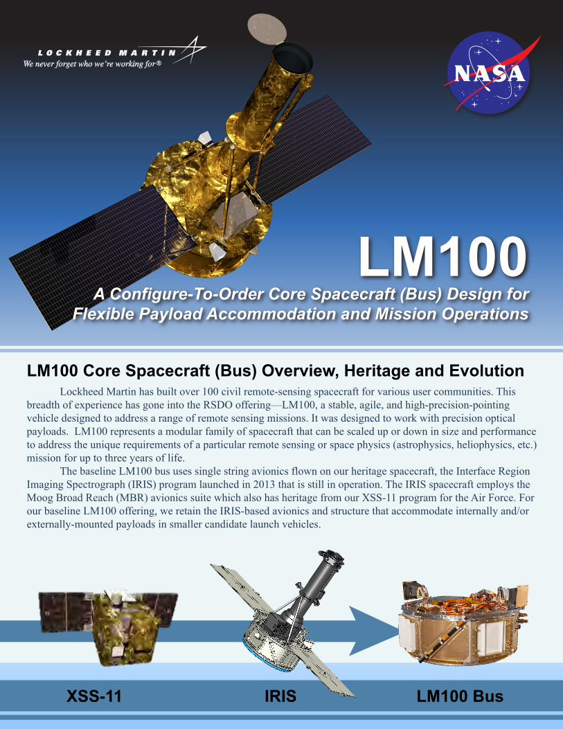
LM100A Configure-To-Order Core Spacecraft (Bus) Design for
Flexible Payload Accommodation and Mission Operations
XSS-11 IRIS LM100 Bus
LM100 Core Spacecraft (Bus) Overview, Heritage and Evolution Lockheed Martin has built over 100 civil remote-sensing spacecraft for various user communities. This breadth of experience has gone into the RSDO offering—LM100, a stable, agile, and high-precision-pointing vehicle designed to address a range of remote sensing missions. It was designed to work with precision optical payloads. LM100 represents a modular family of spacecraft that can be scaled up or down in size and performance to address the unique requirements of a particular remote sensing or space physics (astrophysics, heliophysics, etc.) mission for up to three years of life. The baseline LM100 bus uses single string avionics flown on our heritage spacecraft, the Interface Region Imaging Spectrograph (IRIS) program launched in 2013 that is still in operation. The IRIS spacecraft employs the Moog Broad Reach (MBR) avionics suite which also has heritage from our XSS-11 program for the Air Force. For our baseline LM100 offering, we retain the IRIS-based avionics and structure that accommodate internally and/or externally-mounted payloads in smaller candidate launch vehicles.

LM100 Platform Capabilities The LM100 is a 95 kg bus that is capable of accepting a range of remote sensing payloads. With the baseline complement of two solar arrays, the bus is capable of providing an orbit average payload power of 155 W. With larger arrays, this can be increased to 373 W. The 3-axis stabilized bus can support payloads of up to 152 kg and maintains a pointing capability of 200 arc-sec per axis with 40 arc-sec knowledge (3-σ), and slew rates of 0.25 deg/sec. The Command and Data Handling subsystem uses the Moog Broad Reach Integrated Avionics Unit which has very successful flight heritage on the IRIS, XSS-11, TACSAT2, and AMS missions. It satisfies all requirements for Commanding, Telemetry, Data Handling, Electrical Power Controls, Payload Storage as well as the Flight Computers that host our Flight Software. It provides Spacewire, LVDS, 1553, RS422, and analog interfaces for payloads. The baseline configuration provides 48 Gbit SDRAM for store and forward payload data.
Mission-Specific Configure-to-Order
LM100 Configure-To-Order BusMeeting a Wide Range of Mission Needs
LM100 BUSBASELINE (RSDO)
Legend: Configure-to-Order ModificationsScalable Modifications
LM100 is configurable and offers a wide range of mission-specific modifications (available at extra cost) for reconfiguring or scaling the core capabilities to meet mission specific requirements, as shown in the figure below. Components such as the global positioning system (GPS) receivers, propulsion, and wide-band communications options, are available in varying mission-unique configurations. The particular configuration required will be determined in response to mission-specific requests for offers.
In the baseline configuration, data is downlinked through an X-band transmitter at 15 Mbps which is scalable up to 50 Mbps. Command and control is handled through an S-band transponder with uplink rates of 2 to 128 kbps, and downlink rates of 4 kbps to 5 Mbps . The LM100 bus structure uses a monolithic machined 6061-T6 Aluminum spacecraft structure consisting of eight bays. The forward, aft, and inner panels are honeycomb construction with aluminum face sheets. Bus equipment is housed in the eight outer bays. Four reaction wheels are housed in the outer bays close to the spacecraft center of gravity. Electronics equipment are mounted to closeout panels that are also the exterior radiators for each bay. In the baseline configuration, the payload is bolted directly to the forward structure of the bus. Payloads can also be mounted through rigid or isolating struts to mount points on the nadir deck. In the bus structure inner octagonal cylinder, an additional section, 97,000-cm3 is available for payload boxes.
Structural Configuration
CommunicationsWide-Band Communications -
X-Band, Ka-Band
StructureCustom Payload I/F
MechanismsSolar Array Gimbals
HGA Gimbals
Command & Data Handling
Custom P/L interface & Mission Sized Memory
Flight SoftwarePayload-Specific Module
Updates
PropulsionCenter Mounted Tank and 0.2 lb Thrusters
StructureLM100
ThermalPassive w/
Heaters
Propulsion(Not In
Baseline)
MechanismsIRIS Solar Array
Deployment Mechanism
Command & Data Handling
Integrated Avionics Unit
Flight SoftwareIRIS Flight Software
Highly Modular
Electrical PowerTwo Wing IRIS Solar Array
Li-Ion Battery
CommunicationsS-Band TransponderX-Band Transmitter
Omni Antennas
Guidance, Navigation & Control• 2-Star Trackers• 6-Sun Sensors• 4-Reaction Wheels
• 3-Torque Rods• 1-Magnetometer
Thermal ModsCustom Radiators
Heat Pipes
GN&C High-Precision ModsHigh-Precision Star Trackers
High-Precision Inertial Reference Unit
GN&C LEO KnowledgeGPS ReceiversGPS Antennas
Electrical PowerCustom Solar Array Designs
(Fixed and Articulating)
Structure• Monolithic machined aluminum frame with aluminum face sheet and honeycomb core panels, and eight machined aluminum radiatorsCommand and Data Handling (C&DH)• Centralized RAD750 processor control supported by 1553B and RS-422 serial connections• Autonomous processor fault protection• Payload data interfaces—LVDS, 1553B, RS-422, Spacewire• Integral Solid State Memory sized to meet mission-specific* storage needsFlight Software• Flight-proven package with heritage back to XSS-11 and IRIS• LMSSC GN&C flight software autocoded from Simulink as application layer of the MBR Bus manager softwareElectrical Power• Two-panel solar array using GaAs triple-junction cells• Lithium-Ion battery of varying capacity • Unregulated 28V busGuidance, Navigation and Control (GN&C)• Zero momentum 3-axis stabilized gyro-less baseline design• Mission-specific* sensors based on precision requirementsCommunications• S-band transponder for command and telemetry (2 to 128 kbps U/L, 4 kbps to 5 Mbps downlink) through omni antennas• X-band transmitter for science data (15 – 50 Mbps D/L) through omni antenna• Mission-specific* wideband systems for data downlink (Ka-Band)Propulsion• Mission-specific* blow-down hydrazine monopropellant system availableThermal• Passive design with redundant heater systems controlled by on-board computer• Dedicated radiators with direct unit mounting and embedded heat pipes available for mission-specific* needsMechanisms• Hold-down and deployment mechanisms• Heritage solar array and antenna gimbals available for mission-specific* applicationsLaunch Vehicle Compatibility• Baseline launch compatibility: Pegasus LV Compatible with Minotaur I, Minotaur IV, Taurus XL, Taurus 2, Athena IIc, Falcon 9, and Atlas V
*Mission-specific modifications available at extra cost
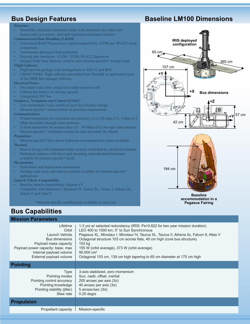
Bus Design Features Baseline LM100 Dimensions
Bus CapabilitiesMission Parameters
Pointing
Propulsion
+X
+Y107 cm
65 cm
365 cm
+Y
+Z
57 cm
42 cm
194 cm
Baseline accommodation in a
Pegasus Fairing
IRIS deployedconfiguration
Bus dimensions
LifetimeOrbit
Launch VehicleBus dimensions
Payload mass capacityPayload power capacity: base, max
Internal payload volumeExternal payload volume
1-3 yrs w/ selected redundancy (IRIS: Ps>0.822 for two year mission duration)LEO 400 to 1000 km, 0° to Sun SynchronousPegasus XL, Minotaur I, Minotaur IV, Taurus XL, Taurus II, Athena IIc, Falcon 9, Atlas VOctagonal structure 103 cm across flats, 40 cm high (core bus structure)152 kg155 W (orbit average), 373 W (orbit average)90,000 cm3
Octagonal 103 cm, 139 cm high tapering to 65 cm diameter at 175 cm high
TypePointing modes
Pointing control accuracyPointing knowledge
Pointing stability (jitter)Slew rate
3-axis stabilized, zero momentumSun, nadir, offset, inertial200 arcsec per axis (3σ)40 arcsec per axis (3σ)5 arcsec/sec (3σ)0.25 deg/s
Propellant capacity Mission-specific
Rapid Spacecraft Development Office (RSDO)NASA Goddard Space Flight CenterMail Code 401.1Greenbelt, MD 20771 USAPhone: 301-286-1289Email to: [email protected]
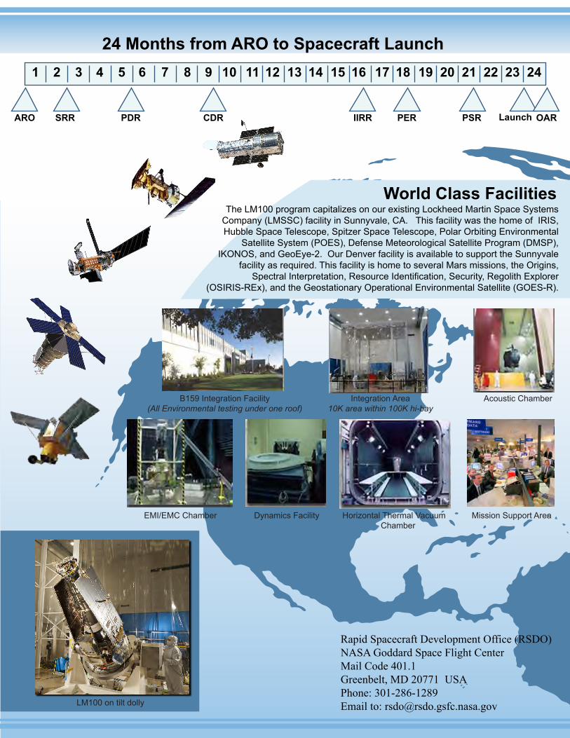
The LM100 program capitalizes on our existing Lockheed Martin Space Systems Company (LMSSC) facility in Sunnyvale, CA. This facility was the home of IRIS, Hubble Space Telescope, Spitzer Space Telescope, Polar Orbiting Environmental
Satellite System (POES), Defense Meteorological Satellite Program (DMSP), IKONOS, and GeoEye-2. Our Denver facility is available to support the Sunnyvale
facility as required. This facility is home to several Mars missions, the Origins, Spectral Interpretation, Resource Identification, Security, Regolith Explorer
(OSIRIS-REx), and the Geostationary Operational Environmental Satellite (GOES-R).
World Class Facilities
24 Months from ARO to Spacecraft Launch1 2 3 4 5 6 7 8 9 10 11 12 13 14 15 16 17 18 19 20 21 22 23 24
LM100 on tilt dolly
EMI/EMC Chamber
B159 Integration Facility(All Environmental testing under one roof)
Integration Area10K area within 100K hi-bay
Acoustic Chamber
Dynamics Facility Horizontal Thermal Vacuum Chamber
Mission Support Area
ARO SRR PDR CDR IIRR PER PSR Launch OAR