a computer module used to calculate the ... computer module used to calculate the horizontal control...
TRANSCRIPT

A COMPUTER MODULE USED TOCALCULATE THE HORIZONTAL CONTROL
SURFACE SIZE OF A CONCEPTUALAIRCRAFT DESIGN
National Aeronautics and Space AdministrationContract Number NCC 2-236
August 1990
Principal Investigator:
Student Assistant:
Dotal R. S_ndlin
Aeronautical Engineering Department
California Polytechnic State University
Stephen Mark SwansonAeronautical Engineering Department
California Polytechnic State University
C_,LrlJI_ATi ]'4 ,H,-_;iTL_NTAL Ci.jNTPc]t_ %U_F&C[-
kC jl lforl_i,:_ : _lvL_chnic .:-,t,if_: jniv.) L?-': k Gj / o 0
https://ntrs.nasa.gov/search.jsp?R=19900017199 2018-05-28T22:57:30+00:00Z

ABSTRACT
A COMPUTER MODULE USED TO CALCULATE THE HORIZONTAL
CONTROL SURFACE SIZE OF A CONCEPTUAL AIRCRAFT DESIGN
Stephen Mark Swanson
January 1990
This paper discusses the creation of a computer module used to calculate the size of
the horizontal control surfaces of a conceptual aircraft design. The control surface size is
determined by first calculating the size needed to rotate the aircraft during takeoff, and,
second, by determining if the calculated size is large enough to maintain stability of the
aircraft throughout any specified mission. The tail size needed to rotate during takeoff is
calculated from a summation of forces about the main landing gear of the aircraft. The
stability of the aircraft is determined from a summation of forces about the center of
gravity during different phases of the aircraft's flight. Included in the horizontal control
surface analysis are: downwash effects on an aft tail, upwash effects on a forward canard,
and effects due to flight in close proximity to the ground.
Comparisons of production aircraft with numerical models show good accuracy for
control surface sizing. A modified canard design verified the accuracy of the module for
canard configurations.
Added to this stability and control module is a subroutine that determines one of thrce
design variables for a stable vectored thrust aircraft. These include forward thrust nozzle
position, aft thrust nozzle angle, and forward thrust split.
PRECEDENG PAGE BLA_,,_,:,-',NOT FILMED
iv

TABLE OF CONTENTS
Page
LIST OF FIGURES
LIST OF TABLES
LIST OF SYMBOLS
CHAPTER
1. Introduction
2. Center of Gravity
3. Horizontal Control Surface Sizing
4. Forward and Aft Center of Gravity Limits
5. Aircraft Stability
6. Aerodynamic Effects
7. Module Verification
8. Vectored Thrust Analysis
9. Additional Aerodynamic Calculations
10. Conclusions and Recommendations
REFERENCES
APPENDIX
A. Module Inputs
B. Sample Output
C. Production Aircraft Layouts
D. Program Listing
vi
vii
ix
1
3
7
14
19
23
31
38
44
54
56
57
62
65
69

LIST OF FIGURES
Figure
1. Aft C.G. limits Relative to Main Landing Gear
2. Summation of Moments about the Main Landing Gear
3. Aft Horizontal Tail Angle of Attack
4. Forward Canard Angle of Attack
5. Summation of Moments about the Center of Gravity
6. Fuselage Stability Coefficient (Kf) vs. Position of Wing
Root Quarter-Chord (Croot/4)
7. Effective Wing Aspect Ratio And Span - Low Speeds
8. Upwash Effects Forward of The Wing (1 - dE/dot) vs.Forward Position in Percent Wing Quarter-Chord (x/cmo t) as
a Function of Wing Aspect Ratio (AR)
9. Ratio of Lift-Curve Slopes in and out of Ground Effect (aJa) vs.
Height Above Ground in Semi-Spans (dg/b/2) as aFunction of the Aspect Ratio (AR)
10. Effective Span of Wing in Presence of Ground
11. Effective Span of Flaps in Presence of Ground
12. Horizontal Tail Size (Sht) vs. Main Landing
Gear Position (Xmg)
13. Forward and Aft C.G. Limits (Xcg fore and Xcg .at) vs.
Main Landing Gear Position (Xmg)
14. Thrust Vector Components and Positions
15. Forward Thrust Vector Position (XT1) vs. Thrust Split (TSPLIT)
for Various Aft Thrust Angles ('}'2)
16. Calculation of Wing Aerodynamic Center by MomentsAbout the Root Quarter-Chord, point A
Page
5
7
11
12
14
21
24
26
28
3O
3O
36
37
39
43
45
vi

Figure
17.NumericalandGraphicalAerodynamicCenterComparisons
18.CurvesUsedin DeterminingtheK 1CoefficientstoCalculatetheStick-FreeEffects. BR, l/A, Ce/C
19.CurveUsedin DeterminingtheK 1CoefficienttoCalculatetheStick-FreeEffects. t/c
20.CurvesUsedin DeterminingtheK2CoefficientstoCalculatetheStick-FreeEffects. BR, l/A, Ce/C
21.CurveUsedin DeterminingtheK2 CoefficienttoCalculatetheStick-FreeEffects. t/c
22.ControlSurfaceEfficiencyFactor('_)vs.PercentElevatorChord(Ce/C)
23.F-16AGeometricLayout
24.SaabJ-37ViggenGeometricLayout
25. Boeing727-200GeometricLayout
26.Boeing727-200AerodynamicData
Page
48
51
51
52
52
53
66
66
67
68
vii

LISTOFTABLES
Table
1.F-16A ProductionandComputerModelComparison
2. Boeing727-200ProductionandComputerModelComparison
3. SaabJ-37ViggenProductionandComputerModelComparison
Page
33
34
35
viii

LIST OF SYMBOLS
a
a
acn
aht
A
AR
AReff
AC
ACSYNT
B
b
bcN
BDMAX
beff
bHT
BODL
BR
b,,
bl
b 2
- Height of aft horizontal tail above trailing vortex core (feet)
- Wing lift-curve slope (per degree)
- Canard lift-curve slope (per degree)
- Tail lift-curve slope (per degree)
- Position of wing quarter-chord at fuselage centerline (feet)
- Aspect Ratio
- Effective aspect ratio in ground effects
- Aerodynamic Center
- AirCraft SYNThesis program
- Angle between C.G. and main landing gear (degrees)
- Wing span (feet)
- Canard span (feet)
- Maximum fuselage width (feet)
- Effective wing span in ground effect (feet)
- Aft horizontal tail span (feet)
- Fuselage length (feet)
- Balance Ratio, BR = ((%/cf) 2- (t/2 of)e) lp2
- Wing trailing edge vortex span (feet)
- Change in hinge moment with respect to angle of attack
- Change in hinge moment with respect to change in elevator angle
ix

C
c/4
Croot
c B
cC
Cf
C.G.
CI
CL
Cla
CLa
CL_HT
CL_cN
C.M. a
CM A
CMcg
CMmg
CMTH
CMwb
D
dCm/dC 1
dCm]dC1 CN
- Wing Mean Aerodynamic Chord (feet)
- Wing quarter-chord point of the Mean Aerodynamic Chord
- Wing root chord (feet)
- Elevator balance chord (feet)
- Elevator mean aerodynamic chord (feet)
- Elevator flap chord (feet)
- Center of Gravity
- 2-dimensional lift coefficient of the wing
- 3-dimensional lift coefficient of the wing
- 2-dimensional wing lift-curve slope
- 3-dimensional wing lift-curve slope
- 3-dimensional tail lift-curve slope
- 3-dimensional canard lift-curve slope
- Pitching moment coefficient change due to change in angle of attack
- Moment coefficient about point A
- Moment coefficient about the Center of Gravity
- Moment coefficient about the main hmding gear
- Contribution of thrust to the pitching moment
- Wing-Body pitching moment
- Aircraft drag
- Total pitching moment-curve slope
- Pitching moment-curve slope contribution of the canard
dCm/dClf
dCm/dC1 aT
dCm/dCl TH
dCm/dCl wing
dE/d(_
de/d_up
dS/d(_
dg
dL
dy
e
H
HFrr
h_rr
iCN
iHr
iw
Kf
LCN
Left
LHT
Lw
- Pitching moment-curve slope contribution of the fuselage
- Pitching moment-curve slope contribution of the tail
- Pitching moment-curve slope contribution of the thrust of the engine(s)
- Pitching moment-curve slope contribution of the wing
- Change in downwash angle with respect to change in angle of attack
- Change in upwash angle with respect to change in angle of attack
- Change in elevator angle due to change in angle of attack
- Height of control surface root quarter-chord above the ground
- Incremental lift force associated with a slice of wing section
- Incremental distance along wing Mean Aerodynamic Chord
- Oswald efficiency factor
- Free elevator factor
- Height of wing above the ground
- Height of aft horizontal tail above ground
- Height of aft horizontal tail above wing chord plane
- Canard incidence angle (degrees)
- Tail incidence angle (degrees)
- Wing incidence angle (degrees)
- Fuselage coefficient
- Canard lift (pounds force)
- Effective length from wing to horizontal tail (feet)
- Tail lift (pounds force)
- Wing Body lift (pounds force)
xi

M A
MAC
Moo
N
No
R
S
SCN
S_
SM
T
T1
T 2
t/c
V
W
XA
Xac
Xac cn
Xac ht
Xac wb
Xc6
KeG aft
- Moment about point A
- Mean Aerodynamic Chord
- Free stream Mach number
- Number of engines
- Neutral Point
- Reaction force of aircraft on the ground (pounds force)
- Wing surface area (sq. feet)
- Canard surface area (sq. feet)
- Tail surface area (sq. feet)
- Static Margin (percent wing chord)
- Total engine thrust (pounds force)
- Thrust of forward thrust vector (pounds force)
- Thrust of aft thrust vector (pounds force)
- Elevator thickness-to-chord ratio
- Aircraft acceleration
- Aircraft gross weight (pounds force)
- Distance from quarter-chord of wing center to aerodynamic center (feet)
- Wing aerodynamic center (percent wing chord)
- Canard aerodynamic center (percent canard chord)
- Tail aerodynamic center (percent tail chord)
- Aerodynamic center of wing-body combination (percent wing chord)
- Distance from nose to aircraft C.G. (feet)
- Aft C.G. limit (feet)
xii

XCG for
X_
XLE root
Xmg
XT1
XT2
7v
Zing
zrl
0t
O_w
_e
8emax
ACLf
Aeg
_g
EV
- Forward C.G. limit (feet)
- Leading edge of wing Mean Aerodynamic Chord from nose (feet)
- Leading edge of wing root from nose (feet)
- Distance from C.G. to main gear (feet)
- Distance from forward thrust vector to C.G. (% fuselage length)
- Distance from aft thrust vector to C.G. (% fuselage length)
- Vertical distance from drag center to main gear (feet)
- Vertical height from main gear to C.G. (feet)
- Vertical thrust line from forward thrust vector to C.G. (feet)
- Vertical thrust line from ",fit thrust vector to C.G. (feet)
- Aircraft angle of attack (degrees)
- Wing angle of attack (degrees)
- Elevator deflection for t',_e off rotation (degrees)
- Maximum elevator deflection for landing (degrees)
- Change in lift coefficient due to flaps
- Change in downwash due to ground effects (degrees)
- Downwash angle of wing on aft horizontal tail (degrees)
- Downwash angle in ground effect (degrees)
- Downwash angle in the wing vortex core (degrees)
xfii

eup - Upwashangleof wing on forwardcanard(degrees)
A - Wing sweepangle(degrees)
T1 - Forwardthrustvectorangle(degrees)
V2 - Aft thrust vector angle (degrees)
- Wing taper ratio
"qCN- Canard efficiency
nHT- Tail efficiency
F - Wing dihedral angle (degrees)
- Control effectiveness factor
xiv

CHAPTER 1
Introduction
In the aircraft conceptual design process, there are five major areas in which the
designer allots most of his or her time and effort. These include aircraft layout,
aerodynamics, weights, propulsion, and performance. In each of these areas the designer
goes through a design process that includes a large and complex series of decisions and
calculations to determine the design parameters of the aircraft. After initial parameters
have been determined, the design is compared to any specified requirements, appropriate
changes are made, and then another series of decisions and calculations is completed to
refine the design. This cycle is repeated until the aircraft design created meets the specified
requirements.
Once the conceptual design has become refined, the designer turns to more detailed
areas in the aircraft design process. One of these areas is that of stability and control.
where the sizes of the control surfaces on the aircraft are determined, the stability of the
aircraft is determined, and where a more refined estimate of aircraft components weight
and position is completed. Once again, as in the conceptual design areas, the detailed
design areas involve a cycle of calculations and decisions in order to create a more refined
aircraft design.
NASA Ames Research Center has created a computer program which does the
calculation part of the conceptual design series. This design program, called ACSYNT
(AirCraft SYNThesis design program), helps the designer in the five areas of the
conceptual design. This includes geometric layout, aerodynamic analysis, weight
calculations, propulsion estimates, and performance analysis. This program allows the
designer to concentrate more on the decisions and less on the complex calculations.

,.)
To enhance the conceptual design process of the ACSYNT design program, the
decision was made to create a module to perform calculations necessary for a longitudinal
stability and control analysis. By performing more analysis of the aircraft's design at an
earlier stage, a more refined product is created during the conceptual design, reducing the
amount of effort required to finalize the aircraft design.
This paper discusses the development of the stability and control module. This
module will be used in conjunction with the ACSYNT design program to enhance the
conceptual design process. The module is used to determine the aircraft's center of gravity
by positioning the different components of the aircraft at positions specified by the
designer. It is used to determine the shift in center of gravity due to fuel and weapons
usage during the aircraft's mission. Finally, it is used to calculate the horizontal control
surface size needed to maintain controllability during take off, mission completion, and
landing. The module is used to determine the horizontal control surface size of an aircraft
which uses either a conventional aft tail, a forward canard, or both.
In order to determine the stability of the aircraft, there are several aerodynamic
parameters that the module must determine. These include the shift in the aerodynamic
center of the wing with respect to Mach number, and the lift curve slope of the canard if
one is being used (lift curve slopes for the wing and aft mounted tail are calculated using
ACSYNT's aerodynamics module). Also, the downwash of the wing on the tail, the
upwash of the wing on the canard, and ground effects are determined using the module.
Also included in this module is an analysis that uses the stability conditions during
landing to calculate three vectored thrust design parameters. The analysis includes the
position of the forward thrust vector, the angle of the aft thrust vector, and the amount of
thrust split between the forward thrust vector and the total thrust. This allows the designer
to create a vertical landing aircraft design which is stable during transition from forward
flight to hover.

CHAPTER 2
Center of Gravity
One of the more important parameters used in stability calculations is the center of
gravity (C.G.). The C.G. is the equilibrium point where the weights of the different
components act as one force at one point. It is a reference point in the aircraft's design in
calculating both the horizontal control surface size, and in determining the stability of the
aircraft design.
Determination of the C.G. is derived from the definition, finding the one point where
all the weights act as one force. This is done by summing all the weights and moments of
the aircraft components about the nose of the aircraft, and dividing the two as shown in
Equation 1.
C°G. _
y_ Moments (1)
Weights
The C.G. position is determined in units of length from the nose. The C.G. provides
a reference point for the summation of aerodynamic moments of the aircraft.
Since ACSYNT is a conceptual design program, there is little information calculated
in ACSYNT about the positions of the different aircraft components. The program
calculates only the positions of the engine(s), wing, vertical tail, aft tail, and forward
canard. Positions for all other components are selected by the designer and input into the
stability program.
The component positions that ACSYNT does calculate are determined in the
following manner. The position of the engine is determined from the value of the length
and position of the engine pod supplied through ACSYNT's geometry module. This can
be modified in the stability module by the designer through adding or subtracting a fraction

of the pod length. The locations of the wing, horizontal tail, vertical tail, and canard are
determined from values of the quarter-chord (C/4) points for each aerodynamic surface as
supplied by ACSYNT. The stability module allows the designer to vary these positions
by adding or subtracting a fracdon of the mean aerodynamic chord (MAC).
All other component positions are left as the designers choice, allowing placement of
the components at any point along the fuselage. The component positions are calculated
using multiplying factors input by the designer. Equation 2 shows an example of this
process where the C.G. of the fuselage is calculated as a function of the fuselage length
(BODL), and a multiplying factor (Xffus). Designer input multiplying factors allow for a
more flexible design process, giving the designer more freedom in the internal layout of
the aircraft. If the designer does not desire to specify any or all of the component
positions, default positions inside the module are used.
Xcg _ = Xfru s * BODL (2)
When determining the stability of the aircraft, it is important to calculate the shift in
C.G. throughout the flight as fuel is used and/or weapons deployed. If the C.G. travels
too far forward or aft during the flight, it can put the aircraft in an unstable condition,
ma.king it impossible to fly.
The ACSYNT program allows the designer to divide the aircraft mission into a
maximum of 12 different phases. The designer specifies for each phase the altitude, range,
Math number, and engine thrust setting of the aircraft. The designer can also specify if
any weapons are to be deployed at the end of a phase. For each phase, ACSYNT
determines the lift, drag, and fuel usage. It can also determine the optimum altitude, and
optimum Mach number. ACSYNT then determines a new aircraft weight for the next
phase of flight by subtracting out the weight of the fuel used and weights of any weapons
deployed.

5
To determinetheshift in theC.G.positionat theendof eachphase,the weightsum
andmomentsumarecalculatedusingtheweightsfor eachphase.To furtherenhancethe
capabilitiesof thestabilitymodule,modificationsweremadeto includetheweightof any
externaltanks. Whenthe amountof fuel usedbecomesgreaterthen theamountof fuel
storedin theexternaltanks,themoduleremovestheexternaltankweights,removingthem
from futureC.G.calculations.
OncetheC.G.hadbeendeterminedandtheC.G.rangecalculated,thepositionof the
C.G. with respectto the point of groundcontactof the main gear is evaluated. The
positionof the point of groundcontactis importantwhendeterminingof thehorizontal
control surfacesize necessaryfor take-off rotation. From U.S. Navy _tircraftdesign
specificationsl, theC.G. shouldbe locatedat least15degreesforward of the maingear,
asshown in Figure 1. This assuresthe aircraft will not accidentally tip over during
groundhandlingoperations,andthatenoughweight rests on thenose gearto maintain
positive nose wheel steeringof the aircraft. The stability module comparesthe C.G.
Figure1" Aft C.G.LimitsRelativetoMainLandingGear
1 Curry,NormanS.; Aircraft Landing Gear Design: Principles and Practice.s,AIAA Education Series; American Institute of Aeronautics and Astronautics, Inc.370 L'Enfant Promenade, S.W., Washington D.C., 20024; 1988; 43 - 50.

6
position calculated for each phase of flight to the position of the main gear. If the 15
degree requirement is not satisfied, the module moves the point of contact aft a fraction of
the fuselage length (0.01 * BODL). It recalculates the C.G. until the requirement is
satisfied. Comparison between the C.G. and the point of contact during all phases of
flight assures the aircraft will meet the requirements if an inflight emergency were to
require landing prior to mission completion.

CHAPTER 3
Horizontal Control Surface Sizing
There are two different methods used in determining the size of the horizontal control
surface. The first method determines the size of the surface necessary to rotate the aircraft
during takeoff. The second method, discussed in a later section, determines if the control
surface size calculated by the first method is large enough to satisfy the forward and aft
C.G. limits of the aircraft. When both methods are satisfied, the aircraft will have a
horizontal control surface large enough to maintain positive longitudinal control.
The first method sizes the horizontal control surface by a summation of moments and
forces about the point of ground contact of the main landing gear on the aircraft, as shown
in Figure 2. The forces on the aircraft at takeoff rotation include: wing lift, horizontal
Xmg- Xaccn
I_z-n L
w
(Zing- ZTI)I
Xmg- XacD
Figure 2:
Xacht- Xmg
Summation of Moments about the Main Landing Gear
control surface lift, wing-body pitching moment, aircraft drag, aircraft weight, and engine
thrust. Also included is the aircraft acceleration. The moment arms for each of these are
taken with respect to their positions from the point of ground contact. This point is used
since the aircraft needs to rotate about the point of contact during takeoff. The wing lift is
positioned at the aerodynamic center (AC). It is modified to include ground effects, which
7

discussedin a later section.The aircraft'sdrag andaccelerationare placedalong the
aircraftcenterline(ACSYNTcalculatesthedragof theentireaircraftandusesthatin all its
calculations. This includesthedrag of the wing, fuselage,and tail surfaces. The total
drag force asdefined by ACSYNT is therefore put at the aircraft's centerline). The
maximumtakeoff weight,asdeterminedby ACSYNT's weightmodule,is locatedat the
C.G. The horizontalcontrol surfacelift, alsomodified for groundeffect, is placedat its
AC. In ACSYNT, theACsof all lifting surfacesarethequarter-chordpoint of themean
aerodynamicchord(MAC). Thewing-bodypitchingmomentis positionedaboutthepoint
of groundcontact. For the takeoff analysis,a conventionaltakeoff is assumed.This
meansthat the forward and aft thrust vectors (T1 andT_) point in the aft direction.
Therefore the only momentscreated by the thrust vectors are due to the vertical
displacements(Zrt and7-q.2) of the two vectors.
The horizontal positions of the wing lift, aircraft weight, and horizontal control
surface lift depend on whether the horizontal control surface used for pitch control is a
conventional aft tail or a forward canard. For an aft tail configuration, the wing lift is
placed forward of the C.G. and the point of ground contact, and the horizontal tail lift is
placed at its AC in the rear of the aircraft. For a canard configuration, the wing lift is
placed behind the C.G., and the canard lift is placed at its AC in the front of the aircraft.
This leads to two different equations for the summation of moments about the point of
contact of the aircraft. A third equation is derived for the case of both a canard and a
horizontal tail. In this case, the canard is assumed to be used only for trim. 2 Its size and
shape are specified by the designer, who then uses the stability module to size the aft
2 The ACSYNT program in its Aerodynamics and Geometry modules is unable to handlecases where there exists both a horizontal tail and a canard on the same aircraft. Having
the designer input the canard size and shape, allows the designer to evaluate those caseswhere both exist.

9
horizontal tail. This uses the same equation as the case with a horizontal tail, but includes
a term for the moment created by the lift of the canard acting at its AC.
Examining first the case for which there exists a horizontal tail only, the equation for
the summation of moments created by the aerodynamic forces about the point of ground
contact 3 is seen in Equation 3. This is modified to account for any vertical thrust offset as
specified by the designer.
Mrng = -CMwbqSc- [Z g-ZT,]T1-[Zmg-ZTtT2W
+ [Xmg- Xac]Lwb + [Zmg- ZD]D + --_/Zmgg
-[Xmg-Xc_]W
-(3)
In this equation, the lift of the wing (Lwb) is replaced with the classic definition
Lwo= CLo _gOtwq S(4)
where the subscript g represents changes due to ground effect which is discussed in the
section titled "Aerodynamic Calculations".
From Newton's equation of motion F = ma, the aircraft acceleration component is
replaced by the forces in the horizontal direction. These forces include thrust, drag, and
the reaction force of the aircraft acting on the runway. This replaces the acceleration term
for the aircraft with
W _/= T- D- I.tR (5)g
3 Roskam, Jan.; Airplane Flight Dynamics and Automatic Flight Controls, Part 1;Published by the author; 519 Boulder, Lawrence KA; Second Printing, 1982; 3/3-375

10
Fromthesummationof forcesin theverticaldirection,it ispossibleto solvefor the
reactionforceof theaircraftactingon theground.
R= W - Lwb- Lht(6)
In order to solve for the minimum tail size needed to rotate the aircraft, the forces
about the point of ground contact must be balanced. To achieve this condition, Mmg in
Equation 3, is set equal to zero.
combination of Equations 3, 4,
The horizontal tail lift (LHT), is solved using the
5, and 6, as seen in Equation 7. Equation 7 is used to
calculate the necessary tail lift in terms of the different aerodynamic forces.
Lht =
L l + L 2 - L 4 - L 6 + L 7 - L 8
A
(7)
where
L 1 = - CMwbq S c
L8 = [Zt_ D
[ -xm -. zm ]= Xacht
It is important to note that the lift required by the horizontal tail to rotate about the point of
ground contact is negative in value (that is pointing down), which requires a negativc
horizontal tail angle of attack. From the classic equation for lift, the horizontal tail lift is
expressed in Equation 8.

11
Lh t = CLotht g (Or w + iht- i w + I; Be) q Sht - CLoth t Eg q Slat(8)
Where the angle of attack of the tail as shown in Figure 3. Rearranging Equation 8,
WindFigure 3: Aft Horizontal Tail Angle of Attack
creates Equation 9. Equation 9 is used to solve for the horizontal control surface size at
take off rotation, while in ground effect.
Sht =Lht (9)
CLaht g (Otw + iht- iw + "_fie) q - Cl-_ht eg q
For the case where there exists both an aft horizontal tail and a forward canard, the
assumption is made that the canard is used only for trim, and not for longitudinal control
purposes. With the size of the canard defined by the designer, the stability module is
used to determine the size of the aft horizontal tail. Modifying Equation 7 to include the
moment created by the canzu'd lift placed at its AC, leads to Equation 10.
where
Lht =L l + L 2 - L 4 - L 6 + L 7 - L 8 + L 9
A
(10)
L9 = [Xmg- Xaccn + P Zmg] CLt_tcn g (O_w Cup + ion- iw)

12
The canardangleof attackis shownin Figure4, wherethesubscript"up" indicatesthe
effectsof upwashdueto thewing.
The casefor which thereexistsonly a canardon the aircraft, a slightly different
equationis deriveddueto the different directions themomentsact aboutthe point of
groundcontact. TheC.G.of theaircraft is now put forwardof thewing AC, which gives
anegativemomentcreatedby thewinglift aboutthepointof contact. Sincethecanardis
placedforwardof theC.G.,themomentcreatedby its lift needsto haveapositivevalueto
balancethemomentequation.Equation11is derivedfrom the summationof moments
Wind
Otcn = Otw +Eup+ ion - iw
Figure 4: Forward Canard Angle of Attack
about the point of ground contact with a forward canard and any thrust offset.
Mmg -CMwbqS C- [Zrng-ZTI]T1- [Zmg-ZTtT2
W
+ + g
IXmg- Xc_W
IXmg- Xaccl Lcn
(11)
Combining Equation 11 with Equations 4, 5, and 6, gives a solution for the canard lift
_ L1 _ L2+ L4+ L6+ LT+ Ls (12)Lcr I _-
A

13
where L 1 through L 6, and L 8 are defined in the same terms as used in Equation 7, and
where L 7 and A are defined as
L7--[Xacwb-Xmg-_ Zmg] Lwb
Zing]Finally, using the classic equation for the canard lift, the canard surface _u'ea is
calculated using
Scn
L_n (13)
CLot g (O_w+ £up + ion- i,_,+ _ 8_) q
The above set of equations are used to determine the size of the horizontal control
surface used for longitudinal control. These equations work for either an aft mounted
horizontal tail, or a forward mounted canard. The next procedure is developed to insure
that the horizontal stabilizer and control surface are large enough to permit an acceptable
amount of C.G. travel while maintaining aircraft stability.

CHAPTER 4
Forward and Aft Center of Gravity Limits
Using the preceding methods, it is possible to determine the minimum horizontal
control surface size for take off rotation, and the C.G. range for the specified mission.
Longitudinal controllability is now determined by calculating the forward and aft C.G.
limits. These limits are then compared to the C.G. range determined. Then if necessary.
the control surface size is increased to encompass the C.G. range within the forward and
"aft limits.
First the forward C.G. limit is determined. This is calculated for the worst possible
case of flight, that is with the aircraft in the landing configuration. This includes effects
due to high-lift at low-speed while in ground effect. Using the minimum horizontal
control surface area calculated earlier, the equation for the summation of moments about
the aircraft's C.G. is determined from Figure 5. This results in Equation 14. The forces
Xcg- XaccnLc-n
I
ZT1
I
_t _ Xacht- XcgXcg - Xac "..--D
CMwbk,7_-
Keg- XT1 T2- Xcg_
"1"2
Figure 5: Summation of Moments about the Center of Gravity
acting on the aircraft in the landing configuration are: the maximum wing lift, wing-body
pitching moment with flaps extended, aircraft drag, horizontal control surface lift, and
forces due to thrust offset. The wing lift is positioned at the AC. The wing-body
14

15
pitching moment is placed about the C.G. As was done earlier, the aircraft's drag is
placed along the centerline of the aircraft (this force then falls out of the equation when
assuming that the C.G. lies along the centerline). The horizontal control surface lift is
placed at its respective AC, and the thrust offset forces are positioned according to the
designer's inputs.
CMcg CL xcg- Xac-- c CMw_-_bw-_+i._-i_+_<)_._(_,_×c_)_c _"_(14)
( }s_(_-×_c_ (w,ZT,+T_ZT_)N+ CLet_ (_w+13up+iCN-iw+'_Se S c rlCN + qSc
To find a solution for the forward C.G. position, the moment coefficient about the
C.G. is set equal to zero, and Equation 14 is rearranged for determination of X g. The
final solution is shown in Equation 15. By setting the moment coefficient to zero, a
solution is calculated for the most forward C.G. position where the horizontal control
surface is just able to maintain the aircraft in a level attitude with maximum elevator
deflection.
(_w-EEL Xac + c CMwb + CLo_rr + iHT-iw + 17 z___k. Xaclrr nlfT
Xcgfore =o
+
C_ N (O{W + Ettp
A
_ScN Xac+ iCN- iw + t O_l -_ _ qCN -
(T1 ZT1 + T2 ZT2} NqS
(15)
where
A
,5= CL + CLlrr(O_w- E+iHT- iw+'rSe}-_--TlHT
+ Ck_ (Otw + Cup + iCN- iw + "t:Be) SCN--g--rlcN

16
In Equation 15, the C L is the maximum lift coefficient, and 8 is the maximum elevator
deflection.
Once the forward C.G. limit is determined, it is compared to the different C.G.
positions calculated for each of the mission phases of the aircraft. If any of these positions
fall forward of the calculated limit, the horizontal control surface size is increased an
incremental amount (5 square feet), and the forward limit is recalculated. This process is
repeated until all the mission C.G. positions fall aft of the forward e.G. limit.
The second comparison for the horizontal control surface size is the calculation of the
aft C.G. limit. The aft C.G. limit is that point where the moments about the C.G. no
longer change with angle of attack. This is written as
dCM cg _ 0 (16)
dot
This aft limit is also known as the neutral point (N 0) of the aircraft. If the C.G. moves
behind this point, the change in moment with respect to angle of attack becomes negative
which makes the aircraft unstable. The N o of the aircraft is determined starting with the
equation for the moment about the aircraft's C.G., Equation 14. Differentiating this
equation with respect to angle of attack results in Equation 17. This includes contributions
dot dot ]
SCN+ CLac_qCN T (x cg - dotup -Ta--a/
(17)

17
of the wing, horizontal tail, and forward canard. The fuselage and thrust vector
contributions are small with respect to the other effects, and are therefore removed from
the differentiation.
The neutral point is determined using the equation derived from the following
procedure. Equating CMa tO zero, and rearranging Equation 17 in terms of Xcg results in
Equation 18. In this equation, the N O is given in percent wing MAC. In order to compare
N o =
Xacwb +xacttr Cl_£t S qHr 1---+I:dot dot]
A (18)
+
C l-axe, S CN ( dc d8
Xacc_ CLet S rlcN /1- +*-dot up dot
A
where
C Lot. r S HI"
A = 1+ Ct_ S filet1 ---+'r + qCN 1 --- +'t
dot Ct_ S dotup dotl
it to the C.G. range determined earlier, the aft C.G. limit must be calculated in units of
length from the nose of the aircraft. The equation used for this calculation is shown ira
Equation 19.
Xcg aft = X LE + MAC N 0(19)
Once the aft C.G. limit is determined, it is compared to the C.G. range. If any the
C.G. positions do not fall forward of the aft limit, then the horizontal control surface is

18
increasedin sizean incrementalamount(5 sq. ft.). The C.G. limit is reevaluated,and
comparedto the C.G. positions. This is repeateduntil the forward and aft limits
encompassall theC.G.positions,andtheaircraftbecomesstablethroughoutall phasesof
themission.
Thehorizontalcontrol surfacesizeis now the minimum sizenecessaryto maintain
aircraft control during takeoff rotation and low speedlanding flight. It is also large
enoughto insurecontrollability, sincethemoduleassurestheC.G. will remain in limits.
Thefinal stepin sizingthehorizontalcontrolsurfaceis todetermineif it is largeenoughto
insureaircraftstabilityduringflight.

CHAPTER 5
Aircraft Stability
In order to determine if the conceptual aircraft design is statically stable in flight, the
pitching moment curve slope (dCMcg/dCL) or the static margin (SM) must be determined.
The aircraft is stable if it has a negative value for the dCM/dC L, the larger the negative
value, the more stable the aircraft. The equation used in solving for the dCM/dC L is
developed from a summation of moments about the C.G., and is nondimensionalized by
dividing by the dynamic pressure, the reference wing area, and the reterence chord length.
(Note that the drag does not appear since it is placed at the C.G. of the aircraft due to the
limitations of the ACSYNT program in its calculations of total aircraft drag.)
CMcg = EL Xcg-c Xac CMwb - Cl__,_r (CZw- E + iHT- iw + • _) SHTs (X:,_,__- X_g) rl_rr
(20)
+ CL_:s {O_w + Cup + iON- iw + T Be} SCNs (Xcg-cXaccN) 'lqCN + {TI ZTlq +ST2cZ1"2} N
which is modified by taking the derivative with respect to the lift coefficient.
dCM Xcg -Xac dfMwb CLxzt, rr SHT (Xac,rr- Xcg}lqHT(1 __0_E__)dCL = c - dCL CL_ S c dR
+ CLc_:sCL_ SCNs (xcg -cXaccN) 1]CN ( 1 - d-_-upde) + (T1 ZTIwc+ T2 ZT2} N
(2l)
19

20
Eachsectionin theequationrepresentsthecontributionof thedifferentaircraftcomponents
suchasthewing, fuselage,aft andforward horizontalcontrol surface,andenginethrust.
The contributionof eachcomponentis calculatedseparately,andtheresultssummedto
determinethetotalaircraftstabilitycoefficient.
Thewing contributionis solvedusing4
Xcg - Xac (22)dCm _dCL wing C
This solution assumes small angles of attack. The contribution of the wing is stabilizing
when the C.G. is forward of the AC, and destabilizing when it is aft.
The contribution of the fuselage and nacelles, dCNwb]dCL, is estimated using the
equation 5
dCMwb _ Kf BDMAX 2 BODL (23)
dCL S c CLa
where the fuselage stability coefficient Kf, is determined from Figure 6. Kf is given as a
function of the position of the wing root quarter-chord.
The contribution of an aft mounted horizontal control surface is solved using _
dCm _ - aHT SHT Xac,n - Xcg de ) (24)dCL HI" - _ S c T]H T {l - _-
4 Perkins, C.D. and Hage, R.E., Airplane Performance, Stability and Control, J. Wiley
and Sons, 1949. 216-218
5 ibid., 229.
6 ibid., 219-220.

21
which includes effects due to downwashof the wing on the tail. In this solution,
stick-freeeffectsareincludedbymultiplyingthehorizontalcontrolsurfacecontributionby
a factor called the freeelevator factor (Fe),determinationof which is discussedin the
chapteron "AdditionalAerodynamicCalculations".
Theeffectof aforwardcanardon thestabilityof theaircraftiscalculatedusing
_ aCNSeN XCNrlCN (1-de) (25)dCLCN a S c _ up
The upwash of the wing on the canard, and the lift curve slope of the canard are calculated
in the section "Additional Aerodynamic Calculations". The stick-free effects are included
in the canard calculations only if there is no aft horizontal tail on the aircraft. If both a
canard and an aft mounted tail exist, then it is assumed the canard is used for trim only.
The stick-free effects for the canard are calculated in the same manner as the stick-free
effects for the horizontal tail.
0.05
Kf
0.04
0.03 ...........
0.02
0.01 .....
0 0 10
Figure 6:
20 30 40
Croo¢4 (% fuselage length)
Fuselage Stability Coefficient (Kf)VS.
.............i................!........
E
t
50 (,0
Position of Wing Root Quarter-Chord (C rooJ4)(Reproduced from Reference 4)

99_m
The contribution of engine thrust is calculated using Equation 26, which assumes that
the lift equals the weight of the aircraft.
dCMm- {TIZTI+T2ZT2}NdCL W c
(26)
Where the contribution of the thrust is due to offset of the thrust vectors from the aircraft
centerline. This solution allows the designer to include effects for multi-engine aircraft
where not all engines are located the same height from the centerline, and engines with
more then one exhaust nozzle creating multiple thrust vectors.
A second measure of aircraft stability is the SM. This is simply the distance the N_ is
aft of the C.G. at any given time during flight. It is an indication of how easy or hard it is
for the aircraft to rotate about the lateral axis. The larger the distance between the N 0 ,rod
the C.G., the larger the SM, and the harder it is tor the aircraft to be rotated. Conversely,
the smaller the SM, the easier it is to rotate the aircraft. The SM is calculated from
X_g XLE (27)SM= N o
C
which gives the distance of the C.G. in front of the N 0 in percent MAC. Accepted values
for the SM for stable aircraft range from 10% MAC for a transport, to 5% MAC for a
fighter (from reference 5). All the aircraft stability and control parameters have now been
determined. There are however a few aerodynamic effects that influence the aircraft which
need to be determined.

CHAPTER 6
Aerodynamic Effects
In calculating the size of the horizontal control surface needed to maintain stability,
certain aerodynamic characteristics that affect the solution need to be determined. Three
important characteristics are included in the stability module. These include the downwash
of the wing on an aft horizontal tail, the upwash of the wing on a forward canard, and
ground effects.
Following a method outlined in reference I, the downwash of the wing on an aft
mounted horizontal tail is calculated 7. This method gives the downwash angle at the tail as
a function of the effective wing aspect ratio (AReff), the effective wing span (beff), and the
tail height above or below the trailing wing vortex. This method assumes a large wing
span to horizontal tail span ratio (b/bht > 1.5), wing trailing edge vortex separation, and
subsonic flow.
First ARcf f and bcf f are determined. These are determined from Figure 7, dependent
on the angle-of-attack and geometry of the wing. Once the ARef f and the bcf f have been
determined, the downwash angle is calculated. Equations 28, 29, and 30 are used to solve
for the span of the vortex core (bv) at the horizontal tail quarter-chord.
b v = bef f -
, [ 2 Lefft 112
(28)
7 Hoak, D.E. et al; USAF Stability and Control Datcom; Wright Patterson AFB Ohio,45433; Revised 1970; sect. 4.4.1
23

24
i
z
l
.6 I
IAngle of attack
cro = a for zero lift
_C = _ at stall
Lm_
A¢/4 = Sweepback at wmquarter chord
_. = Wins taper _tzo
A,f r = Effective wingaspect rallo
betf = Errective wnn 8 span
.8
i
1.0
.8
m b_rrb
.6.
0 I .4
Ii i
1.0 .4I
II
Ii
I/X-O
I
i I P t_
.6
i
X.= 1.0
I'i
I
I
1.0
i
/
i ,
'ii q
i i
Figure 7: Effective Wing Aspect Ratio and Span- Low Speeds
(Reproduced From Reference 1)

25
where Left is the distance from the wing tip trailing edge to the horizontal tail quarter-chord
and _ru is a dummy variable. The following are used in solving for bv.
and
by, = [0.78 + 0.10{k-0.4)+ 0.003Ac/4]beff (29)
0.56 ARef f (30)= CL
Equation 31 is used to solve for the height of the horizontal tail above or below the trailing
wing vortex core (a). This is a function of the tail height above the wing chord line (hr_T),
and the effective distance from the wing vortex separation to horizontal tail.
( 0.41CL] - _--_tan(F). (31)
Finally, the ratio of the downwash at the tail to the downwash at the vortex core is
calculated using
1 (32)
l + fL /2tbvJ
where the downwash at the vortex core is determined from
1.62 C L (33)Ev --
rt AR
where the AR for this equation is the actual wing AR, and not effective.
The upwash effects of the wing acting on a forward canard are determined as a
function of wing AR, wing root chord (Croot), and the distance the canard is ahead of the

26
wingquarter-chord.TheupwasheffectsaredeterminedusingFigure88. This solutionis
accurateonly for Machnumberslessthenone,andassuchcurrentlylimits theanalysisto
subsonicmissions.
i
2.0
1.8
1.6
1.4
%
f +I
.......... _6 8
z"..e".,+ ]/I JP" ! i i
" _ i i _"
1.2 _
E _
1.0 ' '0.0 0.4 0.8 1.2 1.6 2.0
x//C root
Figure 8: Upwash Effects in Front of the Wing(1 - d e/dot)VS.
Forward Position in Percent Wing Quarter-Chord (x/c root)as a Function of Wing Aspect Ratio (AR)
Since principal sizing of the horizontal control surface is computed at takeoff or
landing, it is important to include ground effects. Ground effects can adversely affect the
horizontal control surface size by decreasing the downwash or upwash angles on the
horizontal control surface. This decreases the overall angle of attack of the surface, which
then increases the control surface size needed to generate the required amount of lift.
There are three areas which are influenced by ground effect. The first two are the lift of
8 McCormick, B.W., Aerodynamics, Aeronautics, and Flight Dynamics, J. Wiley and
Sons, 1979. pg. 520.

27
thewing andthelift of thehorizontalcontrolsurface.Thethird is thedownwashangleof
thewing onthehorizontalcontrolsurface.
As discussedearlier,when sizing the horizontalcontrol surface,it is necessaryto
calculatethe lift producedby the wing and the lift required of the horizontal control
surface. Oncethesehavebeendetermined,it is a simplematterof modifying them to
includegroundeffects. Groundeffectsincreasetheclosertheaircraftis to theground.To
getmaximumeffectof thegroundon thehorizontalcontrol surfacesize,theheightof the
aircraftabovethegroundis reducedto aminimum. Theminimumpossibleheightoccurs
whentheaircraft is restingon thegroundwith landinggearextended.This heightis used
alongwith Figure9 to calculatetheratioof lift-curve slopesin andoutof groundeffect9.
Oncethechangein the lift curveslopeis determined,the wing lift in groundeffect is
calculatedusing
= OtwqSLwb CLot g(34)
the horizontal tail lift is determined using
Lht= CLoth t g(O_w+ iht -i_+ _ Be)q S ht- CLothtEg q S ht(35)
and the canard lift is found using
Lcn = CLetcn g(_W+ Eup + icn- iw+'t 6e) q Scn(36)
In determining how ground effects influence the downwash angle, the method used
calculates the change in downwash as a function of several wing and horizontal tail
9 Perkins, C.D. and Hage, R.E.; Aim lane P_rf0rm_tnce, Stability and Control;
J. Wiley and Sons, 1949; 257.

28
geometric and aerodynamic parameters 1°. These include effective wing span, wing aspect
ratio, wing taper ratio, wing height above ground, and horizontal tail height above
ground. These also include the wing lift coefficient, and the change in wing lift coefficient
due to flaps. The effective span of the wing is determined as a function of the wing lift,
1.20
1.16
I ......
t\
1.12 1 ,_
a ' i
1.08
1.04
li i...... il ......
\ A.I i i_,.4! i i iN_..6 I ] i
1.000.0 0.2 0.4 0.6 0.8 1.0 1.2 1.4 1.6 1.8
b/2
Figure 9: Ratio of Lift Curve Slopes in andout of Ground Effects (aria)
VS.
Height above Ground in Semi-Spans (dg/b/2)as a Function of Aspect Ratio (AR)
the change in wing lift due to flaps, and the effective wing and flap span ratios, as
calculated using Equation 37. Once the effective span is calculated, the change in
downwash is determined using Equation 38, where H is the wing height above the
10 Hoak, D.E. et al; USAF Stability and Control Datcom; Wright Patterson AFB Ohio,45433; Revised 1970; sect. 4.7.1

29
ground,andHm- is theheightof the horizontaltail aboveground.
changein downwashangleis goodfor Machnumberslessthanone.
This solutionfor the
bef f =
Ct_ + ACLf
AC L_Ct_+
bw bf
(37)
where
bw= b
and where
b
The ratios bw'/b, and bf'/b w' are determined using Figures 10 and 11.
AEg =(38)

3O
O9
08
b,v_____2b
07
10
0 I 3 4
1|
2 |/X
l1
, I
5
Figure 10: Effective Span of Wing in Presence of Ground(Reproduced from reference 1)
10
08
0.6
_by_bw'
O4
02
O0O0
I iI i
02
I 1
! i i I ', !
04 _ 06 08
b
Figure 11: Effective Span of Flaps in Presence of Ground(Reproduced from reference 1)
10

CHAPTER 7
Module Verification
The stability module was validated by comparing computer generated data of two
types of aircraft to data available on the production aircraft. Computer models of a
General Dynamics F-16A and a Boeing 727-200 where generated for comparison using
the ACSYNT program. These computer models matched various parameters of the
production aircraft which included geometry, aerodynamics, and weights. A comparison
was then made between the horizontal control surface size for the production aircraft
versus the control surface size calculated using the stability module.
The method used to solve for the horizontal control surface size consists of three main
steps. First, the different aircraft components are placed along the fuselage. It is
important to place the major components of the aircraft in their specific locations. These
include the wing, horizontal control surface, engine(s), fuel in the fuselage, fuel in the
wing, and the main landing gear. Once the components are in place, the C.G. position
and range for the actual aircraft is matched in the computer model, allowing for a shift in
C.G. from the fully forward to fully aft positions. This matching necessitates the moving
of less important components to different positions, or recalculating the weights of some
components. After determining the C.G., the ACs of the wing and horizontal control
surface are compared to assure the lift forces are acting at the correct positions.
Once the C.G. position, C.G. range, and the ACs correspond to their respective
positions on the actual aircraft, the horizontal control surface sizes are compared. The
results, which are presented in Tables 1, and 2, show excellent agreement between the
actual and computer aircraft. Since more data was available for the F-16A, the solution of
the computer module matched best with the production aircraft.
31

32
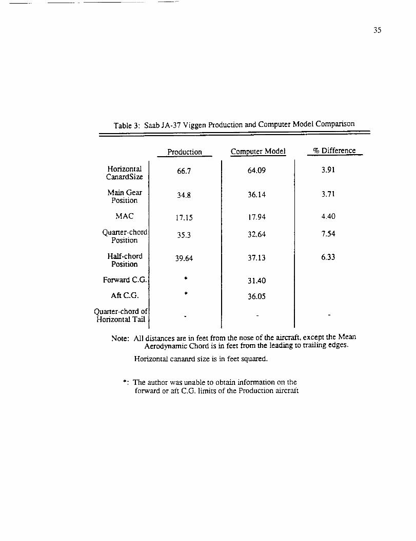
To validate the module for an aircraft with a forward mounted canard, the geometry
and weight of the F-16A model was modified to match the dimensions of a Saab Viggen.
The comparison for this model is shown in Table 3. This showed good accuracy, with an
error in the canard size of only 3.91 percent.
An important factor in these tables is the position of the main landing gear. The
stability module uses rotation about the main landing gear to determine the size of the
horizontal control surface. It was found that the position of the main landing gear at take
off had a large effect on the calculated size. Using the F-16A as an example, Figure 12
shows that small changes in main landing gear position can effect the calculated control
surface size. Figure 13 shows how changes in main landing gear position affect the
forward and aft C.G. limits. Note in both of these figures the tail size and the C.G. limits
stabilize when the main gear fall at or forward of the 60 percent fuselage length. This is a
result of the stability module forcing the main gear aft to satisfy the 15 degree angle
requirement between the main gear and the C.G.

33
Table1" F-16AProductionandComputerModelComparison
Production Computer Model % Difference
HorizontalTail Size
Main GearPosition
MAC
Quarter-chordPosition
Half-chordPosition
Forward C.G.
Aft C.G.
Quarter-chord ofHorizontal Tail
49.0
29.0
11.3
25.6
28.4
41.5
48.18
28.69
11.20
25.55
28.35
26.10
27.21
41.32
1.67
1.07
0.88
0.20
0.18
0.43
Note: All distances are in feet from the nose of the aircraft, except the MeanAerodynamic Chord is in feet from the leading to trailing edges.
Horizontal tail size is in feet squared.
*: The author was unable to obtain information on theforward or aft C.G. limits of the Production aixcra.ft

34
Table2: Boeing727-200ProductionandComputerModelComparison
Production Computer Model % Difference
HorizontalTail Size
Main GearPosition
MAC
Quarter-chordPosition
Half-chordPosition
Forward C.G.
Aft C.G.
Quarter-chord ofHorizontal Tail
376.0
66.18
15.5
63.3
67.2
lit
113.7
379.64
68.47
13.98
62.84
66.34
62.14
65.19
113.44
0.96
3.34
9.81
0.73
1.28
0.23
Note: All distances are m feet from the nose of the aircraft, except the MeanAerodynamic Chord is m feet from the leading to trailing edges.
Horizontal tail size is in feet squared.
*: The author was unable to obtain information on the
forward or aft C.G. limits of the Production aircra.ft
35
Table3" SaabJA-37ViggenProductionandComputerModelComparison
Production Computer Model % Difference
HorizontalCanardSize
Main GearPosition
MAC
Quarter-chordPosition
Haft-chordPosition
Forward C.G.
Aft C.G.
Quarter-chord ofHorizontal Tail
66.7
34.8
17.15
35.3
39.64
64.09
36.14
17.94
32.64
37.13
31.40
36.05
3.91
3.71
4.40
7.54
6.33
Note: All distances are m feet from the nose of the aircraft, except the MeanAerodynamic Chord is in feet from the leading to trailing edges.
Horizontal cananrd size is in feet squared.
*: The author was unable to obtain information on the
forward or aft C.G. limits of the Production aircraft

36
6-
4O0
350
300
250
2O0
150
100
50
!
it
Xmg (% fuselage length)
Figure 12: Horizontal Tail Size (Sht)VS.
Main Landing Gear Position (Xmg)
0.5 0.6 0.7 0.8

3?
30
"F=25
_5 20
50
4s i i i t
35 i i i t
t /t _ ij / i 1
i 1 _' ! !1 _/ ! ,, !
i Y I_Ei i i i i i• ' i _ _
! J
li
it
i i i ,,-T'-¢_i ' ! _! !i i '",L I _ '
,,, t \sx_,o,4,,I110 l l ' ! !' J ilio i ] ! i 1 t t_!, I ! !
0.50 0.55 0.60 0.65 0.70 0.75 0.80 0.85 0.90
Xmg (% fuselage Length)
Figure 13: Forward and Aft C.G. Limits (Xcg fore and X_g aft)VS.
Main Landing Gear Position (Xmg)

CHAPTER8
VectoredThrustAnalysis
Thestabilityandcontrolmoduleincludesasubroutinewhichallows for thevectoring
of thrust during landing. This gives the designerthe ability to evaluateaircraft with
hoveringand vertical landingcapabilities,usingthe stability equationsto createstable
designs.
This subroutineis usedto calculateone of threedifferent parametersfor a stable
aircraft in high-lift, low-speedtransitioningflight.
forwardthrustvector position(XT1), the aft thrust
The three parametersinclude the
vector angle (22), and the thrust
split betweenthe forward thrust vector and the total thrust available (TSPLIT). The
stabilitymoduleis usedto solvefor thesethreeparametersbecausetheyhavethegreatest
impacton theaircraft'sdesign.Theforwardthrustvectorpositionhasa greateffecton the
internalarrangementof theaircraft. It representsa large lift producingsystem,either
ductingfrom themainengine,or a separateauxiliary lift engine. It thereforerequiresa
largeamountof internalvolume,limiting theplacementof otheraircr',fftcomponents.The
aft thrustvectorangleandthethrustsplitdeterminetheamountof bleedair thatis removed
from themain engine. This hasa directeffecton thesizeandthrustof theengine. The
morebleedair removedfromtheengine,the largerit needsto be.
The forward thrustangleis notconsideredimportantsincethemosteffectivethrust
angleis at 90 degreesto the ground. The aft thrust vector position is not considered
importantin thestabilitymodulebecauseit is moreeconomicalboth in designandweight
of theengineto put theaft thrustattherearof theaircraft(asin conventionalaircraft).
Thegenerallayoutfor thethrustvectoranglesanddistancesis shownin Figure 14,
which showsdistancesfor boththeC.G.andthemaingear. Duringtake off andcruise
38

39
flight, it isassumedthethrust vectorspoint in theaft direction, aswith a conventional
aircraft. This allows thedesignerto include any thrustoffsetdueto thepositionsof the
engines.During landing,thethrustnozzlesare"rotated"andthethrustforcesareapplied
in boththehorizontalandverticaldirections.
Xt2
Xtt
_____71_ Tlsin71
TI cos 71
Xcg
Za
Zmg
Xmg
L.E.
MAC
Figure 14: Thrust Vector Componentsand Positions
Summation of the thrust and aerodynamic forces about the C.G. result in the familiar
equation for CMcg (Equation 14). This now includes the thrust forces shown in Figure
14, the final result shown in Equation 39.
CM = CL(xcg- X_} Sin- (X_c,¢-Xcg)rlm (39)'_ C CM'*b- CL_'rO_HI'---S - C
SC, N (Xacc_-Xcg) T1 siny 1
+ CL_O_cN S c rlCN + [xcg- XTI] q S c
T 1 c°$71 T 2 siny 2 T 2 cosT2
4- ZT1 q S c [XT2" Xc_ qSc + ZT2 q S c

4O
In order to maintain stability, the summation of moments about the C.G. is set equal to
zero. Solutions can now be found for the forward thrust vector position, the aft thrust
vector angle, and the thrust split.
Solving for X1.1 is a straight forward algebraic rearrangement of the moment equation
given above. Equation 40 is used to solve for the forward thrust vector position in units
of length from the nose of the aircraft. This solution is for a stable aircraft in low speed
flight transitioning from forward flight to hover.
SUMVT q S c (40)XT1 = + Xcg
Tl siny 1
where SUMVT is given by
cL{XCg - Xa_ SHE (Xacllr - Xcg)SUMVT = c CM,b- CL_frOCHy S c ql-n"
SCN (Xacc_- Xcg) T1 cosy 1+ CL_cr_ °ten S c rlcN + ZT1 q S c
T 2 sin]' 2 T2 cosy 2+ ZT2 S c-E x4 qsc q
By definition, the thrust split (TSPLIT) is the ratio of the forward thrust over the total
thrust. A solution for the thrust split can be determined by using relationships between the
forward thrust, the aft thrust, the total thrust, and the thrust split. The first relationship
comes from the definition of the thrust split, as shown in Equation 41. The second
T1 (41)TSPLIT - THRUST
relationship comes from the assumption that the aft thrust equals the total thrust minus the
forward thrust (this ignores any frictional and heat losses in the forward thrust).

41
T 2 = THRUST - T 1 = THRUST{1 - TSPLIT}(42)
Equations 41 and 42 are substituted into Equation 39, which is rearranged to solve for
TSPLIT. The final solution is shown in Equation 43.
TSPLIT =
SUMVT sin72 cos 72
THRUST XTE_g -_ + ZT2 q S-----_ (43)
A
where
SUMVT = CL (Xcg- Xa_ Stir (Xac,¢ - Xcg)C CM_b- CL_r_HT S c ]]HF
SCN (X acc_- Xcg) ,
+ CL_c_0tCN S c rlCN
and
c0s72 sin72 sin71 cosy 1
A -- ZT2- q S c XT2( t S c XTI q S------_ ZT1 q S-----c
Solving for the aft thrust vector angle (72) is more involved because it appears in the
moment equation twice, once in a sine function, and once in a cosine function. Since a
direct solution can not be found, an iterative approach is used. The boundaries of the
solution are known to be 0 degrees and 90 degrees, and are therefore as starting points.
The moment equation, Equation 39, is solved for CMcg with 72 set to 0 degrees, and with
72 set to 90 degrees. The two solutions are compared, and the one that has the largest
magnitude for CMcg is reduced to halfway between the two boundaries. The moment
equation is recalculated for the remaining boundary and for the new boundary value.
Again, the solution with the largest magnitude for CMcg is reduced to halfway between the
two boundaries. This series of computations and comparisons continues until the

42
magnitude for the moment equation approaches zero. The corresponding _2 is a solution
for a stable aircraft design for transition from horizontal flight to hover.
The vectored thrust subroutine was used to compare the forward thrust vector
positions to the thrust split, and the aft thrust vector angle. The results of this can be seen
in Figure 15.

43
0.6
0.5 ¸
0.4
-_ 0.3I-.
X
0.2
0.1
0.00
7"2(Degree_ _"
///_,-, Vf/
\
///;.C
TSPLIT
Figure 15: Forward Thrust Vector Position (XT1)
VS.
Thrust Split (TSPLIT) for Various
Aft Thrust Angles (yz)
This graph is for an F-16A modified with
with a forward nozzle set at _'= 90 degrees and
with the aft nozzle set at a position of
0.95 percent of body length.

CHAPTER9
AdditionalAerodynamicCalculations
In theACSYNT designprogram,mostof theaerodynamicparametersneededbythe
stabilitymodulearesolvedfor in theaerodynamicsmodule.However,somevariablesare
not solvedfor andothersarecurrently impossibleto transferbetweenthe two different
modules. Theseadditionalvariablesarecalculatedinsidethestability moduleusingthe
methodsdiscussed,astakenfrom thespecifiedreferences.
Theaerodynamiccenter(AC) of thewing is thefirst of theaerodynamicvariablesto
bedetermined. In theaerodynamicsmoduleof ACSYNT, theAC is assumedto be the
quarterchordpointof theMAC of thewing, dependentonly on thegeometryof thewing
andnot theMach numberof the aircraft. This is not an accuraterepresentationwhen
designing high speedfighter aircraft. The aerodynamicsmodule does, however,
determinethechangein the lift-curve slopeof thewing with achangein Math number.
This informationcan beusedto determinethechangein AC with the changein Math
numberwith afair degreeof accuracy.
Figure 16showstheforcesanddistancesusedin thecalculationof theACIt. The
summation of moments about point A results in Equation 44. This equation is
nondimensionalizedby dividing by thedynamicpressure,thewing chord,andthewing
area.This equationis then reducedbytakingthederivitivewith respectto theangle-or-
b b
fb _-c2 f_ _-MA = q CMacdY - q cC ly tan Ady (44)
-- 22
11 McCormick, B.W., Aerodynamics, Aeronautics, and Flight Dynamics, J. Wiley and
Sons, 1979. pg. 484 - 485.
44

45
/
/
Figure 16:Calculation of Wing Aerodynamic Center
by Moments about Root Quarter-Chord, point A.
attack. Noting that by definition the moment coefficient about the AC (CMAc) does not
change with angle-of-attack, it is therefore zero. This reduced form of this equation is
shown in Equation 45.b
d CMA CI cx (45)
dot S y tan A dyb
5-
Defining X A to be the distance from the point A to the AC, the the moment about the
AC (MAc) is defined as the summation of the moment about point A (MA), and the lift

46
forcemultipliedby thedistanceXA. This is seenin Equation46.
Mac= M A + L X A(46)
This equationcanbenondimensionalizedbydividing by thedynamicpressure,thewing
chord,andthewing area.Thiscanalsobereducedby takingthederivativewith respectto
angle-of-attack.This resultsin Equation47, againnoting thatthemomentabouttheAC
doesnotchangewith changein angle-of-attack.
dCM A XA-CLa c
do_(47)
The distanceXA is determinedusingtheequationthat resultsfrom thecombinationof
Equations45and47,asshownin Equation48.
X A -- C1_1-S c ClaytanAdy±
(48)
This general equation is simplified by assuming a constant lift curve slope along the
span of the wing (thereby removing it from the integral), and by assuming a linearly
tapered wing (thereby removing the integral completely). This simplified form is shown
in Equation 49.
Xac = 1 +'_ ) _-/_'tan Aj_--t_La I'E""+
(49)
This equation is used to calculate the position of the AC from the point A (the
quarter-chord point of the wing center), and accounts for wing sweep and taper ratio. The
final step is to account for the effects due to Mach number.

47
The only aerodynamic characteristic in this equation is the ratio of the
two-dimensionalto three-dimensionallift curve slopes. It is thereforenecessary to
determinethechangein the lift curveslope with respectto Machnumber. This works
well with theACSYNT designprogramsincetheonly variablethatACSYNT determines
Macheffectson is thethree-dimensionallift curveslopeof thewing. Thestabilitymodule
therefore needsonly to be used to determine the ratio of the two-dimensional to
three-dimensionallift curveslopestoincludeMacheffectson theAC.
Theratioof two-dimensionalto three-dimensionallift curveslopesisdeterminedby
rearrangingEquation4812 .
CLa =
Clc_
57.29 C_e1 + _AR
(5O)
The AC is now determined for any geometric shape, and at varying Mach numbers.
It was found that this method is good for Mach numbers up to Mach 1.2, at which
point the AC changes at a rapid rate. Comparisons between the method used in the
stability module and a graphical method discussed in Reference 1, are shown on Figure
17. This shows the AC shift for a Boeing 727-200 in subsonic flight, and a F-16A in
subsonic and supersonic flight. The equations used to determine the AC tend to give a
higher value, averaging 4% for the 727-200.
The second aerodynamic parameter not determined in the aerodynamics module of
ACSYNT is the three-dimensional lift curve slope of the canard. A solution is found first
using the Helmbold equation 13, Equation 51. This gives the three-dimensional lift curve
12 Perkins, C.D. and Hage, R.E., Airplane Performance, Stability and Control,
J. Wiley and Sons, 1949. pg. 220.
13 McCormick, B.W., Aerodynamics, Aeronautics, and Flight Dynamics, J. Wiley and
Sons, 1979. pg. 137.

48
Crool.6
A tan A El-
6.,
5
3
2
I
tan AI. E
St Supersonic
[_ 0 tan ALE
tan ALl: ` tan At. I-
---- Numerical Results > B727-200..... Graphical Results
Numerical Results > F-16A..... Graphical Results
Figure 17: Numerical and Graphical AerodynamicCenter Comparisons
(Graph Reproduced From Reference 1)

49
CLa = Cla AR (51)
slope as a function of the two-dimensional lift curve slope and the AR of the canard.
Equation 51 is modified to include the effects of canard sweep angle and Math number
through modification of the two-dimensional lift curve slope 14. Sweep angle effects are
included by the multiplication of the two-dimension',d lift curve slope and the cosine of the
sweep angle. The Mach number effects are included through division of the
two-dimensional lift curve slope by the Pradtl-Glauert compressibility factor. The
compressibility factor depends on the subsonic or supersonic flow. The final
three-dimensional lift curve slope equation is
Cla ARCt_ = (52)
This equation is simplified somewhat in the stability module by assuming the
two-dimensional lift curve slope of the canard equals two-pi.
Also in the stability module, the contribution of the horizontal control surface is
modified to include the effects of a stick-free condition. This is determined by calculating
the hinge moment parameters of the elevator. The method is used to modify the
contribution of the horizontal control surface to the dCM/dCt, and the equations for the
control surface lift. This is done by multiplying with the free elevator factor (Fe) 15,
which is calculated from
d 5 bl (53)F e = l-x--= 1-Zb--- _
dot
14 ibid., 283 - 284.

50
Whereb1 and b2 are determined from the multiplication of the coefficients found in
Figures 18, 19, 20, and 21. These are given as functions of the elevator span, t/c, AR,
and balance ratio (BR), each specified of the designer.
b 1 = -0.55 kl(ce/c ) kl(t]c) kl(BR) kx(1/A)(54)
b 2 = -0.89 k2(ce/c ) k2(t]c) k2(BR) k2(1/A) (55)
The control effectiveness factor ('t), is determined from Figure 22 as a function of elevator
to stabilizer chord ratio.
15 ibid., 495 - 508.

51
i ii!....t 7
08 " ! " "
'"_ ! t i i
! i i i _ ! i, i
{.) (.)
0 0 0 ] 0" 0]5 0 4 0 b
Figure 18: Curves Used in Determining the kl Coefficients toCalculate Stick-Free Effects. BR, l/A, Ce/C
-,_.
06
._7 <:, ,'1
':el f i
"1 i• I.!
....E
-,..-. ....
_07
0 6
0 5
0 4
)00
,_ I, I I
i i t i_i
i i _ _ I i -
' _' i' I , ,..
0 04 008 0 12 0
Figure 19: Curve Used in Determining the kl Coefficients toCalculate Stick-Free Effects. t/c

52
"2
Cp 6 [ i \
\06°_
r[ C' ,1 _' "
.... f
k
,1, l celt..... ! ! ' '
I
1_) 1) (]) i
Figure
BR !
0 ,_"_ 0 5 0 ,I 0 b
20: Curves Used in Determining the k2 Coefficients toCalculate Stick-Free Effects. BR, l/A, Ce/C
._ C' 8
() 6
(.) 4
0 0 0
[004 008 0 i 2 016
Figure 21: Curve Used in Determining the k2 Coefficient toCalculate Stick-Free Effects. t/c

53
1.0
0.8
Figure 22: Control Surface Effeciency Factor (z)VS.
Percent Elevator Chord (cdc)

CHAPTER10
ConclusionsandRecommendations
Theuseof adesignprogramcanenhancemanyareasin theconceptualaircraftdesign
stage.NASA AmesResearchCenterhascreatedacomputerprogram,ACSYNT, which
doescalculationsof aircraft geometry,aerodynamics,propulsion,missionperformance,
andweights. This allowsdesignersto examinea wide rangeof designsin a relatively
shortperiodof time,to createthebestpossibleaircraft.
A stabilityandcontrolmodulewascreatedto enhancetheconceptualdesignprogram,
ACSYNT. This modulecalculatesthesizeof thehorizontalcontrolsurface,thecenterof
gravity for eachmission phase,the forward and aft centerof gravity limits, and the
longitudinalstabilityof thedesign. Thestabilitymodulecalculatesthecontrolsurfacesize
neededfor takeoff rotation,it examinesthestabilityof theaircraftduring themission,and
it determinesif thetail sizeis largeenoughto maintaincontrollability during landing. If
thetail sizeis not largeenoughto meetanyof thesegoals,it is increaseduntil stabilityand
controllabilityareestablished.
Comparisonsbetweenproductionaircraftandcomputermodelsshowthatthestability
module accurately sizesthe tail size for a rangeof aircraft types. Three aircraft, a
B727-200transport,and a F-16A fighter, and a JA-37 Viggen fighter with a forward
mountedcanard,wereusedto evaluatethe stability module. In eachcase,thetail size
determinedby themodulewasanaccuraterepresentationof theactualaircraft.
In addition to analyzingthe horizontalcontrol surfacesizeandthe stability of the
aircraft,ananalysiswasdoneto evaluatevectoredthrustapplicationson thedesignof a
conceptualaircraft. This allowsthedesignerto evaluateoneof threedifferentparameters
associatedwith vectoredthrust systems,whilemaintainingstabilityof theaircraft during
54

55
landing. Theseinclude theforward thrustvector position, theaft thrust angle,andthe
thrustsplit. Theseparametersweredeterminedto bethemostimportantin thedesignof
theaircraft. Theforwardthrustpositionaffectingtheinternallayoutof theaircraft,andthe
aft thrustvectorangleandthethrustsplit affectingtherequiredthrustof theengine.
Recommendationsfor improvementon thismoduleincludethefollowing:
Calculationsof aerodynamiccenterat higherMachnumbersthanwhatis currently
beingused.
Includecalculationsto determinethedownwashandupwasheffectsof thewing at
supersonicMachnumbers.
Calculationsof groundeffectson theupwashof thewing.
Modification of wing lift to includeinteractionbetweenthe wing andthecanard
vortices.
- In theVectoredthrust analysis,include theability to augmentthe forward thrust
with anafterburner,ductburner,or ejector.
In theVectoredthrustanalysis,includechangesin lift andpitchingmomentdueto
jet interaction.

REFERENCES
AmericanInstituteof AeronauticsandAstronauticsProfessionalSeries.Study in Aircraft Design: The Boeing 727; American Institute ofAeronautics and Astronautics; Sept. 14, 1978.
Curry, Norman S. Aircraft Landin_ Gear Design: Principles and Practices,AIAA Education Series; Americffn Institute of-Aeronautics and Astronautics,
Inc. 370 L'Enfant Promenade, S.W., Washington D.C., 2(X)24; 1988
Hoak, D.E. et al. USAF Stability _nd Control DatcQm; Wright Patterson AFB
Ohio, 45433; Revised 1970.
Jane's Publishing Inc. Jtme's All the World's Aircraft, 1984-1985: Jane'sPublishing Inc., 13th Floor, 135 West 50th Street, New York, NY 10020;
1984.
McCormick, B.W. Aerodynamics, Aeronautics, and Flight Dynamics,; J. Wiley
and Sons, 1979.
Miller, Jay. Acrqgraphl, General Dynamics F-16 Fighting Falcon; Aerofax
Inc., Austin TX, 1982.
Nicolai, Leland M. Fundamentals of Aircraft Design; Mets Inc. 6520
Kingsland, San Jose CA 95120; Revised 1984.
Perkins, C.D. and Hage, R.E. Airplane Performance, Stability and Control; J.
Wiley and Sons, 1949.
Roskam, J. Airplan_ Flight Dynamics and Automatic Flight Controls, Part 1;Published by the author, 519 Boulder Lawrence KA 66044; Second
Printing 1982.
56

APPENDIX A
Module Inputs
The following is a list and description of inputs used by the stability and control
module. All the input variables have default values, so not all of the variables need to be
input. The user inputs these in the namelist 'STABIN' and selecting the module number 5
in the COPES inputs.
Format for the 'STABIN' namelist includes a title line, a maximum of 80 characters
long, followed on the next line by '$STABIN' and then the desired inputs. Finally, at the
end of the inputs, a 'SEND' statement is needed to tell ACSYNT the input has been
completed.
Example:
******* Stability and Control Inputs, F-16A Falcon *******
$STABIN ETACN=.90, XT1=0.40,
XFCREW=0.25, XFINST=0.21 .........
SEND
Name Default Description
---Real format ..................................
Angle of attack of the wing at take off rotation. (degrees)AWTOT 2.00
CBALHT 0.00
CELV 0.30
ETACN 0.90
ETAHT 0.90
Percent chord of the longitudinal control
surface ahead of the hinge line.
Percent chord of the horizontal stabilizer
that is the movable surface.
Canard efficiency.
Horizontal tail efficiency.
57

58
ELVDEF - 10.00
ELVDMAX - 15.00
GAMAT1 0.00
GAMAT2 0.00
ICN 0.00
IHT 0.(X)
SCN 1 0.0
SPANCN1 0.0
TRCN 1 0.0
TSPLIT 0.00
TZCHT 0.10
VROT 0.30
WLGFRT 0.30
XFAMMUN 0.30
XFAPU 0.95
XFBB2 0.50
XFBOD 0.50
Amount of elevator deflection needed for
takeoff rotation. (degrees)
Maximum amount of elevator deflection needed for
controllability at low speed. (degrees)
Forward thrust nozzle rotation angle from
the horizontal. (degrees)
Aft thrust nozzle rotation angle from the
horizontal. (degrees)
Canard incidence angle. (degrees)
Horizont',d tail incidence angle. (degrees)
Area of canard when both a canard and an aft tail
are being used (feet2).
Span of the canard when both a canard and an aft
tail are being used (feet).
Taper ratio of the canard when both a canard and
an aft tail are being used.
Percent thrust split, front-to-rear.
Elevator thickness-to-chord ratio.
Mach number at take off rotation.
Weight ratio of front-to-rear landing gear
for C.G. calculations.
C.G. position of the ammunition in percent BODL (fuselage
length).
C.G. position of A.P.U. in percent BODL.
C.G. position of advanced weapons in percent BODL.
C.G. position of body in percent BODL.

59
XFBOMB
XFCAN
XFCARGO
XFCREW
XFELT
XFENG
XFEP
XFEX
XFFFUS
XFFS
XFFUR
XFFWG
XFHDP
XFItT
XFINST
XLECN
XFLIFTF
XFLGFRT
XFLGR
XFMISS
XFNA
0.50
0.20
0.50
0.10
0.05
0.50
0.50
0.50
0.50
0.60
0.50
0.50
0.50
0.20
0.15
0.0
0.50
0.10
0.55
0.50
0.98
C.G. position
C.G. position
Aerodynamic
C.G. position
C.G. position
C.G. position
C.G. position
pod length).
of bombs in percent BODL.
of the canard in percent of the Mean
Chord from the leading edge.
of cargo in percent BODL.
of crew in percent BODL.
of Avionics in percent BODL.
of the engine in percent of PODL (engine
C.G. posmon of electrical system in percent BODL.
C.G. posluon of fuselage external tank in percent BODL.
C.G. posmon of fuselage fuel in percent BODL.
C.G. posmon of fuel system in percent BODL.
C.G. posmon of furnishings in percent BODL.
C.G. poslnon of the fuel in the wing in percent BODL.
C.G. posluon of the hydraulics and pneumatics
in percent BODL.
C.G. position of the horizontal tail in percent of the Mean
Aerodynamic Chord from the leading edge.
C.G. position of the instruments in percent BODL.
Leading edge position of canard when both a
canard and an aft tail are used (feet).
C.G. position of the lift-fan in percent BODL.
C.G. position
C.G. position
C.G. position
C.G. position
of the nose gear in percent BODL.
of the main gear in percent BODL.
of the missiles in percent BODL.
of the nacelles in percent PODL.

6{}
XFPA
XFPAYL
XFPIV
XFSC
XFVT
XFWG
XT1
XT2
ZFD
ZFMG
ZFT1
ZFT2
ZMU
ZRTCN1
0.55
0.50
0.65
0.70
0.20
0.15
0.30
0.60
0.00
2.00
0.0O
0.00
0.02
0.0
C.G. position of passenger accommodations
in percent BODL.
C.G. position of any payload in percent BÚDL.
C.G. position of the control surface pivots
in percent BÚDL.
C.G. position of control surfaces in percent BODL.
C.G. position of the vertical tail in percent of the Mean
Aerodynamic Chord from the leading edge.
C.G. position of the wing in percent of the Mean
Aerodynamic Chord from the leading edge.
Horizontal position of the forward thrust vector in percent
BODL.
Horizontal position of the aft thrust vector in percent BODE
Vertical distance of the aircraft centerline from the C.G. in
percent BDMAX (maximum fuselage length).
Vertical distance of the main gear from the C.G. in percent
BDMAX.
Vertical distance of the forward thrust vector from the C.G.
in percent BDMAX.
Vertical distance of the aft thrust vector from the C.G. in
percent BDMAX.
Friction coefficient of the runway on the
main gear.
Height of the canard quarter-chord above the aircraft
centerline (feet).

61
---Integer Format .......................
IAS 0 Trajectory mission phase in which ammunition is used.
IBS 0 Trajectory mission phase in which bombs are dropped.
ICGPRT 0 Print flag to output aircraft component C.G.
positions for C.G. analysis.
IDBPRT 0 Print flag to output a greater amount of information during
each mission phase, used for debugging purposes.
IETANK 0 Used to specify various positions of any external tanks on
the aircraft.
0 a single tank at the fuselage centerline.
1 Two tanks mounted on the sides of the fuselage.
2 Two tanks mounted on the wing quarter-chord.
3 Two wing-tip tanks.
4 One fuselage centerline tank and two tanks mounted at the
wing quarter-chord.
5 One fuselage centerline tank and two wingtip tanks.
6 Two wing quarter-chord and two wingtip tanks.
IMS 0 Trajectory phase in which missiles are used.
IVECT 0 Used to specify which vectored thrust parameter is to be
solved for.
0 No vectored thrust variable is to be solved for.
1 Calculate longitudinal position of the forward thrust vector.
2 Solve for the Forward over aft thrust ratio (Thrust Split).
3 Solve for the angle of the aft thrust vector from the
horizontal axis.
1 Total number of trajectory phases.NPHASE

APPENDIX B
Sample Output
62

63
AIRCRAFT COMPONENTWEIGHTSAND POSITIONS
COMt_NENT WIEGHT POSITIONAIRFRAME 17022.544922 42.939999
WING 17129.294922 64.515587CANARD 0.000000 0.000000HT 1581.655640 114.010048VT 1310.330078 107.414925
NOSEGEAR 1223.618774 11.300000MAIN GEAR 2855.110352 70.512001NACELLS 1503.169800 45.200001PIVOTS 0.001953 45.200001AIR COND. 309.482300 44.365093
APU 605.342590 70.059998AVIONICS 1441.599487 1.130000
ELECTRICAL 1902.595215 22.600000INSTURMENTS 796.524597 5.650000HYDRAULICS 563.688660 56.500000CONTROLSURF 2981.909424 56.500000
PA 0.000000 45.200001FURNISHINGS 450.000000 36.160000ENGINES 6954.871582 91.914490FUEL SYS. 1682.630249 33.900002LIFT FAN 0.000610 56.500000PAYLOAD 60.000000 22.600000
CREW 510.000000 11.300000CARGO 0.000000 33.900002
AMMUNITION 0.000000 33.900002BB2 0.000000 56.500000
BOMBS 0.000000 56.500000MISSILES 0.000000 53.110001FUS.FUEL 0.000 56.500000WING FUEL 16347.398 64.235992
MISSION PHASENUMBER 1XCG = 64.0515594XAC = 64.0994263DCMDCL = -0.0539999NEUTPT = 0.4538571STATIC MARGIN = 11.7050486AFT CG = 65.6878738
SUMMO = 5729981.000000DCMDCLT = -0.05395812DCMDCLF = 0.00338223DCMDCLJ = 0.00000000LWB = 33122.109375 LHT=SHT = 379.950439 SCN =
XCGFRWD[ 1] = 61.9601
SUMWT= 89458.882813DCMDCLW = -0.00342405DCMDCLCN = 0.00000000
-9019.528320 LCN= 0.0000000
0.000000
B727-200 Center of Gravity Output and Detailed Output

64
STABILITY OUTPUTDATA
TAIL SIZE= 379.9504395XCGFRWD = 62.3969193AFT CG = 65.0767975
DATA AT ENDOFTAKE-OFFXAC = 63.1220779NEUTPT =XCG =CGBAR =DCMDCL =STATIC MARGIN =
MISSION PHASENUMBERXAC =NEUTPT =XCG =CGBAR =DCMDCL =STATIC MARGIN =
MISSIONPHASENUMBERXAC =NEUTPT=XCG =CGBAR =DCMDCL =STATIC MARGIN =
MISSIONPHASENUMBERXAC =NEUTPT =XCG =CGBAR =DCMDCL =STATIC MARGIN =
MISSION PHASE NUMBERXAC =NEUTPT =XCG =
CGBAR =DCMDCL =STATIC MARGIN =
MISSION PHASE NUMBERXAC =NEUTPT =XCG =CGBAR =DCMDCL =STATIC MARGIN =
sq. ft.ft.
ft.
ft.
0.410145064.0528641 ft.33.6899948 % chord
0.00470937.3245034 % chord1
64.0994263 ft.0.4538571
64.0515594 ft.33.6806602 % chord
-0.05399997.3338361% chord
264.4846954 ft.
0.474031764.0514832 ft.33.6801147 % chord-0.07840657.3343816 % chord3
64.1274567 ft.0.4552816
64.0369263 ft.33.5759850 % chord-0.05681897.4385114 % chord4
64.5148773 ft.0.4756619
64.0367661 ft.33.5748367 % chord-0.08140767.4396572 % chord5
64.2071304 ft.0.4593702
64.0241013 ft.33.4842453 % chord-0.06275947.5302525 % chord
END STABILITY OUTPUT
B727-200 Final Stability Output

APPENDIXC
ProductionAircraft Layouts
65
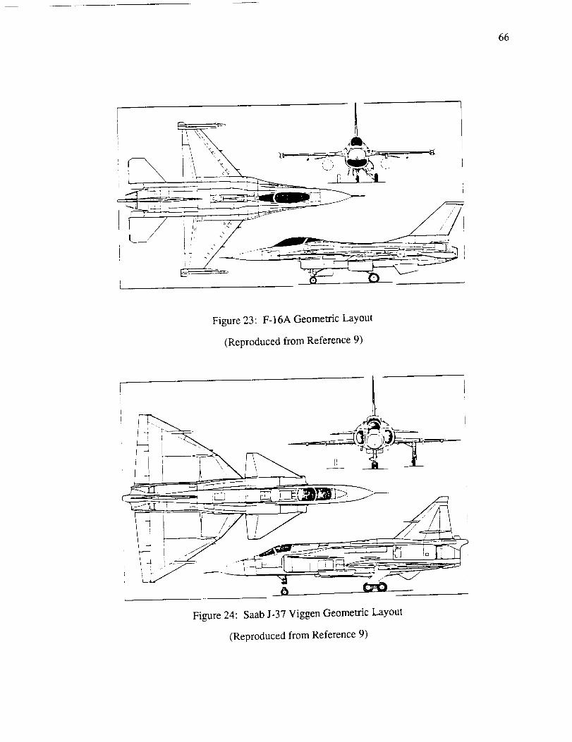
66
Figure 23: F-16A Geometric Layout
(Reproduced from Reference 9)
Figure 24: Saab J-37 Viggen Geometric Layout
(Reproduced from Reference 9)

67
jj -(_
Figure 25:B727-200 Geometric Layout
(Reproduced from Reference 2)

6_
3.50-
3.40-
0.30"
EL
0.20,
0.10,
0.00
0.01
Mach.76.78
0.015 0.02 CD 0.025 0.030.035
Figure 26:B727-200 Aerodynamic Data
(Reproduced from Reference 7)

APPENDIXD
ProgramListing
69

70
CCCCCCCCCCCCCCCCCCCCCCCCCCCCCCCCCCCCCCCCCCCCCCCCCCC
CC
SUBROUTINE STBLTY
THIS SUBROUTINE IS USED IN CONJUCTION WITH NASA AMES AIRCRAFT DESIGNPROCRAM 'ACSYNT'. THIS PROORAM CALCULATES THE SIZE OF THE HORIZONTAL
CONTROL SURFACE FOR EITHER AN AFT TAIL OR A FORWARD CANARD. IT CAN
ALSO HANDLE AN AIRCRAFT WITH BOTH CONTROLS, BUT IT DNLY SIZES THE AFT
TAIL, THE SIZE OF THE CANARD IS AN INPUT FOR THE USER.THIS SUBROUTINE ALSO CALCULATES THE CENTER OF GRAVITY OF THE AIRCRAFT,
THE CENTER OF GRAVITY SHIFT DURINO THE TRAJECTORY MISSION, AND THEFORWARD AND AFT CENTER OF CRAVITY LIMITS IMPOSED BY THE SIZE OF THE
HDRIZDNTAL CONTROL SURFACE.IT ALSO DETERMINES THE PITCHINO MOMENT CURVE SLOPE (DCM/DCL) OF THE
AIRCRAFT FOR EACH PHASE IN THE MISSION.THE REFERENCES SITED THROUGHOUT THE PROGRAM ARE LISTED AT THE END
OF THE LISTING.STEPHEN SWANSON 4/89
..,,,,.,,,,,,,,,,,,,,,,.,,,*,*,*o,*,,,,,,,*'''""""**"*'"'"*"****"**• THE FILE 'STBCM.INC' MUST BE IN THE SAME DIRECTORY AS THIS MODULE• FOR IT TO WORK. THE FILE CONTAINS ALL THE COMMON BLOCK STATEMENTS '
• NEEDED TO RUN THIS MODULE. THE 'INCLUDE' STATEMENT IS USED TO *
• INCLUDE THE FILE IN WITH THE MODULE DURINC COMPILATION. S.M.S. 1/89 *
• THE FOLLOWING IS A LISTING OF THE STBCM.INC FILE ...... *
• THIS CONTAINS THE COMMON BLOCK STATEMENTS NEEDED TO RUN THE STABILITY *
• AND CONTROL MODULE 'STBLCON.FDR'. THIS FILE IS CONNECTED WITH THE *• MODULE THROUGH THE 'INCLUDE' STATEMENT FOUND AT THE BEGINING OF EACH *
• OF THE SUBROUTINES.t
, COMMON/OVER/ICALC,NERROR,MDDNO,IGEO,KCPRNT,IGPLT,IF
. COMMON/STBCM/CLALFA,CLAFHT,DEDA,XqCBCN,XqCBWG,XqCBHT,X_CBVT, ", 1 CBARCN,CBARWG,CBARHT,CBARVT,RDOTWG,TRWG,XLEWC,SPANWG, *. 2 SWPWC,PODL,EN,BODL,XLEPOD(IO),WCAND,WFTOT,FUFRAC,WWING,WFS, *
• 3 WLG,WHT,WVT,WE'TANK,WFEXT,WBODY,WAIRC,WAPU,WSC,WENO,SCN,SWC,SHT, *• 4 SVI',WCREW,WELT,WEP,WHDP,WINST,WNA,WPA,WCARCO,WAMMUN,WBOMB'WMISS' *• 5 ARWG,DIHED,ZRTWG,ZRTHT,ARVT,SWPCN,TRCN,AMTO, *• 6 ZRTCN,VOLB,BDMAX,FRN,FRAB,ALPHA,CL,THRUST,ARHT,TNT(12)'WFT(12)' *• 7 WFTO,WTOT,ARCN,CMWB,WGTO,WFEq,WBB2,WAF,WE,WPL,WPS,WTSUM,WFUEL, *• 8 TWTO,MACH,ALT,SWETWG,SWETHT,SWETCN,SPANHT,SPANCN,• 9 STARTM(12),DUMMY,IAO
XFHT XFNA XFVI" XFWC XFAPII XFENC. COMMON/LOCALS/ETAHT,XFCAN, , , , , , ,• I XFELT,XFEP,XFINST,XFHDP,XFPA,XFPAYL,XFFFUS,XFCREW,WPAYL,XFFUR,• 2 XFLCFRT,WFLGFRT,XFLCR,XFFS,XFBOMB,XFSC,XFP_V,XFLIFTF,WPIV,WFUR, +• 2 XEFI,XFAMMUN,XFBB2,XFMISS,XFCARGO,XACWC,ETACN,ODEDA,XAWB,CLACN' *
• 3 WZET,WZEF,WEFF,WEFW,XEF2,WEFWT,WZENG,SU_AMO,SUMWT,XLE,LWB,LI'TWB, *• 3 IDBPRT,XCG(13),DCMDCL(13),SM(13),XCGAFT(13),WLGFRT,WLCR,WFWG,• 4 WFP,WZB,WZM,WZA,IBS,IMS,IAS,NPHASE,ICOPRT,WLFTF,WFFUS,LHT,LCN,• 5 CELV,CBALHT,TZCHT,FNEUTPT(13),XFBOD,X_FWG,XFEX,XLETIP,IETANI(,. 6 ZMTOR,AVFTOT,ZMU,XT1,XT2,ZFMO,ZMG,ZFTI,ZT!,ZFT2,ZT2,ZFD,ZD'TI'
• 7 TSPLIT,GAMAT1,GAMAT2,1HT,ICN,ELVDEF,VROT,ALPHACN,TAU,T2, *• 8 SHTI,SCN1,ELVDMAX,IWG,XCOFRWD(13),QTDR,CCBAR(13),ALFTO,CLTO, *

7]
C * 8 CDTO,CMWBTO,ALFMAX,CDMAX,CMWBMAX,ALFO,CLO,CDO,CMWBO,XLECN' *C * 9 TIRAD,T2RAD,XLECG,XLETI,XLET2,CLMAX,CLAHTGRD,CLACNGRD,IVECT' *C * 1 SPANCNI,ZRTCNi,ARCN1,TRCNI,ALFHT,ALFCN,DCMTMUL,TWZTO *
C • COMMON/XCOS/XBOD,XWINO,XCAN,XHT,XVT,XNA,XPIV,XAIRC,XAPU,C * 1 XELT,XEP,XINST,XHDP,XSC,XPA,XENG(IO),XFS,XLIFTF,XFUR, *
C * 2 XPAYL,XCREW,XCARGO,XAMMUN,XBB2,XBOMB,XMISS,XETANK'C * 3 XFUSF,XWGFUEL,XLGFRT,XLGR,LFLAG
C * REAL XACWG,DCMDCLF,DCMDCLT,DCMDCLW,DCMCLCN,KF,CSC,TC,MBDD,C * 1 MCAN,MWG,MFS,MLG,MHT,MVT,METANK,MFEXT,MAIRC,MAPU,MSC,MENO(IO), *C • 1 LWB,LH1,LH2,LH3,LH4,LHS,LH6,LHT,LHB,LHg,LC1,LC2,LC3,LC4,LC5, *C • 2 LC6,LC7,LCS,LHT,LCN,ZMTOR,ZMU,L_,IWG,IHT,ICN,LEFF,MACH, *C * 2 MCREW,MELT,MEP,MHDP,MINST,MNA,MPA,MCARGO,MAMMUN,MBOMB,MMISS' *
C * 3 MPAYL,MPIV,MLIFTF,K11,K12,K13,K14,K21,K22,K23,K24
C
C
INCLUDE 'STBCM.INC'
IF (ICALC.GT.I.) GO TO 10READ IN THE INPUT PARAMETERS.
CALL STABINPT
I0 CONTINUE
IF (ICALC.NE.2.) O0 TO 20DO ALL THE NECESSARY CALCULATIONS.
CALL STABCALC1
2O CONTINUE
IF (ICALC.NE.3.) GO TO 30DO A FINAL PRINTOUT OF THE DATA.
CALL STABOUT
30 CONTINUE
RETURN
END
CSUBROUTINE STABINPT
CC THIS SUBROUTINE READS IN THE INPUT FRnM THE TNP,FT P.T.LECREATED F_YC THE USER IN NAMELIST 'STABIN' IT ALSO INITILIZES ALL VALUES SOC THE USER DOES NOT NEED TO SPECIF.TY ALL VALUES, ONLY THE ONES DESIRED.
CINCLUDE 'STBCM. INC'
C NAMELIST/STABIN/ETAHT, XFCAN ,XFHT, XFNA, XFVT, ×FWO, XFAPU ,XFBB2 ,
I XFPIV,XFELT,XFEP,XFINST,XFHDP,XFPA,XFFFUS ,×I:BOD,XFFWG,XFCARO, O,2 XFLOFRT,WFLOFRT,XFLOR,XFFUR.XFMT-_,XFAM U .×FPAYL,XFEX XFFS

72
2 XFSC,XFBOMB,XFENG,XFLIFTF,XFCREW,IDBPRT,CELV,CBALHT,TZCHT,
3 ETACN,AWTOT,ZMU,XT1,XT2,ZFMG,ZFTI,ZFT2,ZFD,TSPLIT,GAMAT1,4 GAMAT2,1HT,ICN,ELVDEF,ELVDMAX,VROT,SCNI,XLECN,
5 SPANCNI,ZRTCNI,TRCNI,IETANK,IBS,IMS,IAS,NPHASE,ICGPRT,IVECTC
CCC ETACN -C XFBOD -C XFCAN -C XFHT -C XFNA -C XFVI -C XFW(; -C XFLGFRT -C WFLGFRT -C XFLGR -C XFPIV -
C XFFUR -C XFAPU -
C XFELT -
C XFEP -C XFINST -
C XFFS -
C XFHDP -C XFSC -
C XFPA -
C XFPAYL -C XFCARGO -
C XFFWG -C XFFFUS -C XFEX -C XFCREW -C XFENG -
C XFLIFTF -C XFBOMB -
C XFBB2 -
C XFMISS -C XFAMMUN -
C IDBPRT -
C CELV -C CBALHT -
C TZCHT -C AW'I'OT -C ZMLI -C XTI -
C XT2 -C ZFMO -C ZFT1 -C ZFT2 -C ZFD -C TSPLIT -C OAMATI
THE FOLLOWING IS A LIST OF THE INPUTS AND WHAT THEY STAND FOR...
ETAHT - AFT HORIZONTAL TAIL EFFICIENCYFORWARD CANCARD EFFICIENCY
FUSSELACE BODY C.G. POSITION IN PERCENT BDDLFORWARD CANARD C.O. POSITION IN PERCENT MAC
AFT HORIZONTAL TAIL C.G. POSITION IN PERCENT MAC
NACELL(S) C.G. POSITION IN PERCENT BODLVERTICAL TAIL C.G. POSITION IN PERCENT MAC
WING C.G. POSITION IN PERCENT MACNOSE GEAR C.G. POSITION IN PERCENT BODL
PERCENT NOSE GEAR OF TOTAL LANDING GEAR WEIGHTMAIN LANDING GEAR C.O. POSITION IN PERCENT BODL
CONTROL PIVOTS C.O. POSITION IN PERCENT BODL
FURNISHINGS C.G. POSITION IN PERCENT BODLAPU C.G. POSITION IN PERCENT BODL
AVIONICS C.O. POSITION IN PERCENT BODL
ELECTRICAL SYSTEMS C.G. POSITION IN PERCENT BDDL
INSTRUMENTS C.G. POSITION IN PERCENT BODLFUEL SYSTEM C.G. POSITION IN PERCENT BODLHYDRAULIC AND PNEUMATIC C.G. POSITIONS IN PERCENT BODL
SURFACE CONTROLS C.O. POSITION IN PERCENT BDDL
PASSENGER ACCDMADATIONS C.G. POSITION IN PERCENT BODL
PAYLOAD C.C. POSITION IN PERCENT BODLCARGO C.g. POSITION IN PERCENT BODL
FUEL IN WING C.G. POSITION IN PERCENT BDDLFUEL IN FUSELAGE C.O. POSITION IN PERCENT BDDL
EXTERNAL TANKS C.G. POSITION IN PERCENT BDDL
CREW C.G. POSITION IN PERCENT BODL
ENGINE(S) C.G. POSITION IN PERCENT PODLengthLIFT FAN C.G. POSITION IN PERCENT BDDLBOMBS C.O. POSITION IN PERCENT BODL
ADVANCED WEAPONS SYSTEMS C.G. POSITION IN PERCENT BODL
MISSILES C.C. POSITION IN PERCENT BODLAMMUNITION C.O. POSITION IN PERCENT BODL
DEBUG PRINT FLAG, CREATES MORE OUTPUT
PERCENT OF STABILIZER WHICH IS MnVABLE ELEVATORPERCENT OF ELEVATOR WHICH IS FORWARD OF THE HINOE LINETHICKNESS TO CHORD RATIO OF THE ELEVATOR
ANGLE OF A'F-rACI(OF THE WING AT TAKE OFF ROTATTON
FRICTION COEFFICIENT OF RUNWAY ON T_RESHORIZONTAL POSITTON OF FORWARD TIIRUST VECTOR PERCENT BODLHORIZONTAL POSITION OF AFT THRUST VECTOR IN PERCENT BODL
VERT. DIST. FROM FUSS. CENTERLINE TO MAIN GEAR, % BDMA×
VERT. DIST. FROM FUSS. CENTERLINE TO FORE THRUST, %BDMAX
VERT. DIST. FROM FUSS. CENTERLINE TO AFT THRUST, %BDMAXVERT. DIST. FROM FUSS. CENTERLINE TO DRAG VECTOR,%BDMA×
FDRWARD THRUST TO TOTAL THRUST RATIO IN PERCENTFORWARD THRUST VECTOR ANGLE, DEnREES

?3
C CAMAT2 - AFT THRUST VECTOR ANGLE, DECREESC SCNI CANARD AREA USED WHEN A.C. HAS A AFT TAIL ALSO, SQ. FT.C XLECN CANARD LEADINO EDGE POSITION USED WITH AFT TAIL, .FEET
C SPANCN] - CANARD SPAN USED WITH AFT TAIL, FEETC ZRTCNi - VERTICAL CANARD HEIGHT USED WITH AFT TAIL, FEET
C TRCNI - TAPER RATIO OF CANARD USED WITH AFT TAIL
C IHT - AFT TAIL INCEDENCE ANGLE, DEGREESC ICN - FORWARD CANARD INCEDENCE ANGLE, DEGREES
C ELVDEF - ELEVATOR ANOLE NEEDED FOR TAKE OFF ROTATION, DECREESC ELVDMAX - MAXIMUM ELEVATOR DEFLECTION FOR LANDING, DEGREES
C VROT - MACH NUMBER AT TAKEOFF ROTATIONC IETANK - EXTERNAL TANK FLAG, USED TO SPECIFY POSITIONS OFC ANY EXTERNAL TANKS. O=TANK ON FUSS. CENTERLINE,I=TWO
C FUSS. SIDE MOUNTED TANKS, 2=TWO MAC MOUNTED TANKS,
C 3=TWO WING-TIP TANKS, 4=ONE CENTERLINE TANK AND TWOC MAC MOUNTED TANKS, 5=CENTERLINE TANK AND WINO-TIP TANKS,
C 6=TWO MAC TANKS AND TWO WING-TIP TANKS.C IBS - INDICATOR TO REMOVE BOMB WEIGHT ON A SPECIFIED MISSON PHASE
C IMS - INDICATOR TO REMOVE MISSILE WEIGHT ON SPECIFIED PHASE
C IAS INDICATOR TO REMOVE AMMUNITION WEIGHT ON SPECIFIED PHASE
C NPHASE NUMBER OF PHASES IN MISSIONC ICGPRT PRINT FLAG TO PRINT C.G. INFORMATION FOR EACH PHASE
C IVECT VECTORED THRUST INDICATOR, O= SOLVE FOR NO VECTOREDC THRUST PARAMETERS, I=SOLVE FOR FORWARD THRUST VECTOR
C POSTION, 2=SOLVE FOR THRUST SPLIT, 3--SOLVE FOR AFT
C THRUST VECTOR ANGLE.
C
C
C
INITIALLZE THE STABIN INPLFr VALUES
ETAHT = 0.90ETACN = 0.90
XFBOD = .50
XFCAN = .20XFHT = .20
XFNA = .40XFMT = .20XFWC = .15XFLCFRT = .10WFLCFRT = .3XFLOR = .55XFPIV = .65XFFUR = .50XFAPU = .gS
XFELT = .05
XFEP = .50XFINST = .15
XFFS = 60XFHDP = .50
XFSC = 70XFPA = 55
XFPAYI_ = .5O
XFCARCO = .50XFFWO = .50

74
XFFFUS = .50
XFEX = .50
XFCREW = .20XFENC = .50
XFLIFTF = .50XFBOMB = .50
XFBB2 = .5oXFMISS = .47
XFAMMUN = .30
IDBPRT = 0
CELV = O.3OCBALH1- = 0.0
TZCHT = 0.I0AWTOT = 2.0
ZMU = .02XT1 = .30XT2 = .60ZFMG = I .0ZFT1 = 0.0ZFT2 = 0.0ZFD = 0.0TSPLIT = 0.0QAMATI = 0.0OAMAT2 = 0.0SCN1 = 0.0XLECN = 0.0
SPANCNI = 0.0ZRTCNI = 0.0TRCNI = 0.0
IHT = 0.0ICN = 0.0
ELVDEF = -]0.0
ELVDMAX = -15.0VROT = 0.3
IETANK = 0
IBS = 0IMS : 0IAS = 0NPHASE = 1
ICGPRT = 0IVECT : 0
READ IN THE VALUES FROM THE NAMEL!ST
IF (ICALC .CT. 1.)READ(5,40) TITLE
READ(5,STABIN)
GO Tn 20n
OUTPUT THE INPUTS TO THE OUTPUT FILE SO THE USER CAN DOUBLECHECK THAT THE VALUES INP_ ARE THOSE DESIRED.
WRITE (6,300)WRITE (6,310) ETAHT, XFBOD, XFCAN
WRITE (6,315) ETACN, WFLOFRT

?5
290
4O3OO31031532033034035O36037O38O3gO4OO4054]O4114]241341441541641_741842043O
WRITE(6,320)XFHT,XFNA,XFV-rWRITE(6,330)XFWG,XFLGFRT,XFLGRWRITE(6,340)XFPIV,XFFUR,XFAPUWRITE(6,350)XFELT,XFEP,XFINSTWRITE(6,360)XFFS,XFHDP,XFSCWRITE(6,370)XFPA,XFPAYL,XFFWGWRITE(6,380)XFFFUS,XFEX,XFCREWWRITE(6,390)XFENG,XFLIFTFWRITE(6,4OO)XFAMMUN,XFBOMB,XFMISSWRITE(6,4OS)XFCARGO,XFBB2WRITE(6,410)CELV,CBALHT,TZCHTWRITE(6,411)AWl'OT,ZMUWRITE(6,412)XTI,XT2,ZFMG
WRITE(6,413)ZFT1,ZFT2,ZFDWRITE(6,414)TSPLIT,GAMATI,GAMAT2
WRITE(6,415)IHT,ICN,ELVDEFWRITE(6,416)VROT,SPANCNI,ZRTCNI
WRITE(6,417)SCNI,XLECN,ELVDMAX
WRITE(6,418)TRCNI,IVECTWIRITE(6,420)IETANK,IBS,IMS,IAS
WRITE(6,430)NPHASE,IDBPRT,ICOPRTCONTINUE
FORMAT(2OA4)FORMAT(//,1HI,15X,28HSTABILITY AND CONTROL
FORMAT(IOX,7HETAHT= ,FIO.5,5X,BHXFBOD= ,FIO
FORMAT(IOX,7HETACN= FIO.5,5X,8HWFLGFRT=,FIOFDRMAT(IOX,THXFHT= FIO.5,SX,8HXFNA= FIO
FDRMAT(IOX,7HXFWG= FlO.5,5X 8HXFLOFRT= FIOFORMAT(IOX,7HXFPIV= FIO.5,5X 8HXFFUR= FIO
FORMAT(IOX,7HXFELT=
FORMAT(IOX,7HXFFS=
FORMAT(IOX,7HXFPA=FORMAT(IOX,7HXFFFUS=
FDRMAT(IOX,THXFENG=
FDRMAT(IOX,7HXFAMUN=FORMAT(IOX,7HXFCARC=
FORMAT(IOX,THCELV=FORMAT(IOX,8HA_FI'OT =
FORMAT(IOX,THXT1 =
FIO.5,5X 8HXFEP=
FIO.5,5X 8HXFHDP=
FIO.5,5X 8HXFPAYL=FIO.5,SX 8HXFEX=
FIO.5,5X,BHXFLIFTF=
FIO.5,5X,8HXFBOMB=
FIO.5,SX,8HXFBB2 =FIO.5,5X,BHCBALHT=
,FIO.5,5X,THZMU =,FIO.5,5X,SHXT2 =
FORMAT(IOX,7HZFTI = ,FIO.5,SX,BHZFT2 =FORMAT (IOX, 7HTSPLIT=, FIO. 5,5X, 8HOAMATI=
FORMAT(IOX,7HIHT = ,F]O.S,5X,BHICN =
INPUTS,//)
5,5X,7HXFCAN=
5)5,SX,7HXFVT=5,5X,THXFLGR=5,5X,7HXFAPU=
FIO 5,5X,7HXFINST=,FIO.5)FIO.5,5X,7HXFSC= ,F10.5)FIO.5,SX,THXFFWG= ,F10.5)FIO.5,SX,THXFCREW=,FIO.5)
F10.5)FIO.5,5X,THXFMISS=,FIO.5)
F10.5)FIO.S,SX,THTZCHT= ,F10.5)FIO.5)FIO.5,SX,7HZFMO = ,FI0.5)
FIO.5,5X,7HZFD = ,F10.5).FIO.5,5X,7HGAMAT2=,FIO.5)
.FIO.5,SX,7HELVDE_=,FIO.5)
,F10.5)
,F10.5),F10.5),F10.5)
FORMAT(]OX,7HVROT = ,FIO.5,SX,SHSPANCN].=.F].O.5,SX,THZRTCNI=,FIO.5)
FORMAT(IOX,7HSCNI = ,F!O.S,SX,BHX_ECN = ,FIO.5,SX,THEI_VDM×=,FIO.5)
FORMAT(IOX,7HTRCNI = FIO.5,SX,BHTVECT = ,_3)FORMAT(IOX,THIETANK=,I3,5X,SHIBS= ,I3,5X,SHIMS= ,I3,5X,5HIAS= ,13)
FDRMAT(IOX,7HNPHASE=,I3,SX,8HIDBPRT= ,I3,SX,8HICGPRT= ,I3)
RE_JRN
END
C

76
SUBROUTINE STABCALC1
CC THIS SUBROUTINE DETERMINES THE WEIOHTS OF FUEL AND WEAPONS ON THEC AIRCRAFT, AND REMOVES THOSE WEIOHTS THAT HAVE BEEN USED DURINGC EACH PHASE OF THE MISSION AS SPECIFIED IN THE TRAJECTORY MODULE.C IT THEN CALLS THE DIFFERENT SUBROUTINES USED FOR CALCULATING
C THE DIFFERENT PARAMETERS AND SIZING THE TAIL.
C,,,,"** NOTE:
CCC
NPHASE, IBS, IAS, AND IMS, SHOULD BE SET IN THE STABILITY
INPUTS TO THE DESIRED VALUES TO ACCOUNT FOR THE NUMBER OF MISSION
PHASES AND THE WEIOHT LOSSES DUE TO THE USE OF WEAPONS.
INCLUDE 'STBCM.INC'
112
IFLAC, = 0CGFLAO = 0
LGFLAC = 0CONTINUE
T = I
IPHASE = 0
XCCFRWD(]) = 0
XCCAFT(2) = BODLSAVES THE ACSYNT CALCULATED WEIOHTS IN LOCAL VARIABLES ANDSETS THE FUEL WEIOHT TO THE MAXIMUM VALUE FOR TAKE-OFF
CONDITIONS.WFP = WFTOTWZB -- WBOMBWZM = WlAISSWZA = WAMMUN
WZET = WETANKWZEF = WFEXT
SIZE THE TAIL FOR TAKE-OFF ROTATION IF IT HAS NOT ALREADY BEEN DONE.
IF(IFLAG .Eq. 0 .AND. CCFLAC .E_. O) THEN
CALL TAILSIZE(I,IPHASE)
ENDIF
IFLAG = 0CGFLAO = 0
CC REMOVE THE FUEL WEIOHT USED IN TAKE-OFF AND MAKE FIRST CALCULAT!ONS.
CHECK TO SEE IF THE FUEL USED FOR TAKE-OFF IS GREATER THEN THE FUEL
IN THE EXTERNAL TANKS. IF TT !S THE TANKS ARE REMOVED.
I=2IF(WFEXT .CT. 0.) THEN
WFP = WFP - WFEXT
IF {WFTO .GE. WFEXT) THENWZET = O.WZEF = O.WFP = WFP - (WFTO-WFE×T)
ELSEWT_EF = WFEXT - WFTO

??
C
C
ENDIFELSE
WFP = WFP - WFTOENDIF
CALL STABCALC2(I,IPHASE,CGFLAG)IF (CGFLAG .Eq. 1)THEN
O0 TO 112
ENDIF
REMOVE THE FUEL WEIGHT USED IN EACH PHASE, AND REMOVE ANY WEAPONS
USED DURING EACH PHASE. ALSO REMOVE EXTERNAL TANKS WHEN THE FUEL
USAGE BECDMES OREATER THEN THE SIZE OF THE EXTERNAL TANKS.
DO 100 IPHASE : I,NPHASE
IF(WZEF .GT. 0.) THENIF (WFT(IPHASE) .GE. WZEF) THEN
WFP = WFP - (WFT(IPHASE)-WZEF)
WZET = O.WZEF = O.
ELSEWZEF = WZEF - WFT(IPHASE)
ENDIFELSE
WFP = WFP - WFT(IPHASE)ENDIF
IF(IPHASE.GE.IBS) WZB = O.IF(IPHASE.GE.IWS) WZM : O.IF(IPHASE.GE.IAS) WZA : O.
I = IPHASE + 2
CALL STABCALC2(I,IPHASE,CGFLAG)
IF (CGFLAG .EQ. 1)THENGO TO 112
ENDIF
CC CALCULATE THE FORWARD C.G. LIMIT FOR THE TAIL SIZE DETERMINED EARLIER.
CCALL XCGFORWARD (I)
CC THESE SET OF INSTRUCTIONS DETERMINE IF THE CENTER OF GRAVITY 13C BEHIND THE FORWARD C.O. LIMIT DETERMINED, AND IF IT IS NnT THEN IT !NCREACF',
C THE SIZE OF THE HORIZONTAL CnNTROI_ 3_RFACE AND RECALCULATES THE
(:FORWARD C.G. LIMIT.
CIF (XCGFRWD (I) .CT. XCG (!))THEN
WRITE (6,300) XCG (I),XCCFRWD (1)IF(SCN .EQ. 0.0) THEN
SHTI = SHTI - 5.0
IFLAG = 1
ELSESCNI = SCNI + 5.0
IFLAO = I

78
ENDIF
OO TO 112
ENDIF
CtO0 CONTINUE
CC THIS SET OF INSTRUCTIONS ACTIVATES THE VECTORED THRUST ANALYSIS
C IF IVECT IS NOT SET TO O.
C
IF(IVECT .EQ. O)O0 TO 200I = NPHASE * 2
CALL VECTHRUST(1)200 CONTINUE
C300 FORMAT(/,IOX,35HWARNINO!! C.G. IS FORWARD OF LIMITS,/,15X,
139H CONTROL SURFACE INCREASED BY 5 SQ. FT.,/,15X,6HXCO = ,F12.6,
25X,IOHXCCFRWD = ,F12.6)RETURN
END
C
CSUBROUTINE TAILSIZE(I,IPHASE)
CC THIS SUBROUTINE IS USED TO CALL THOSE ROUTINES NEEDED TO SIZE THE
C HORIZONTAL TAIL AT TAKEOFF.
CINCLUDE 'STBCM.INC'
CC DATATRANS SUBROUTINE TRANSFERS OVER THE NECESSARY AERODYNAMICS
C PARAMETERS.
CCALL DATATRANS
CC THIS SUBROUTINE DOES ALL THE SECONDARY AERODYNAMICS CALCULATIONS.
CCALL STABCALC3 (I,IPHASE)
CC THIS SUBROUTINE DETERMINES THE TAIL SIZE NEEDED FOR ROTATION.
C
CALL TOROTATE (I,IPHASE)C
RETURN
END
SUBROUTINE STABCALC2(I,IPHASE,COFLAG)
C£ THIS SUBROUTINE IS USED TO CALCULATE ANY PARAMETERS NEEDEDC BY THE SUBROUTINES WHICH ARE NnT CALCULATED PY THE REST OF ACSYNT.
CINCLUDE 'STBCM.INC'

"/9
C2OO
CCCCCCCC
THIS SERIES OF INSTRUCTIONS SETS THE MACH NUMBER EITHER TO THETAKE DFF MACH NUMBER OR THE MACH NUMBER AT THE START OF A MISSION
PHASE. IT THEN CALLS AERODYNAMICS TO GET THE NEW CLALPHA OF THE
WINO AND THEN CALLS THE AERODYNAMIC CENTER SUBROUTINE.
IF(IPHASE .EQ. O) THEN
IF(AMTO .LE. O.O)THENAMTO = VROT
ENDIF
MACH = AMTO
ELSE
MACH = STARTM(IPHASE)ENDIF
ICALC = 2
IAO = l
CALL STBDT(ICALC,NERR,IOEO,KOPRNT,IOPLT)ZCLALFA = CLALFAZMACH = MACH
NOW CALCULATE THE AERODYNAMIC CENTER INCORPERATINO MACH EFFECTS,
SWEEP ANGLE EFFECTS, AND TAPER EFFECTS.
CALL XACCALC(ZMACH,ZCLALFA)
NOW CALCULATE THE CENTER OF ORAVITY OF THE AIRCRAFT.
CALL XCCCALC (I)
CONTINUE
THE FOLLOWING SERIES OF COMMANDS CALCULATE THE PITCHINO MOMENT
CURVE SLOPE FOR THE AIRCRAFT. THESE CALCULATIONS ARE BASED ON
EQUATIONS TAKEN FROM REFERENCE 4, CHAPTER 5. THEY INCLUDE THE
TAIL, WING, CANARD, FUSELACE, AND JET(S).
•,TAIL CONTRIBUTION TO AIRCRAFT STABILITY
CSC=CLALFA,SWO,CBARWO
DCMDCLI=-CLAFHT,SHT],(XqCBHT-XCG(1))*ETAHT*(I.-DEDA)/CSC
THIS ACCOUNTS FOR STICK FREE EFFECTS, DETERMINED IN STABCALC3.
DCMDCLT=DCMDCLI*DCMTMUL
**CALCULATE THE P!TCHTNO MOMENT 31_OPE CONTPTRUT_ON DUE TOTHE CANARD. NOTE THAT THERE ARE TWO SETS nr COMMANr_$FOR
THE CANARD, ONE FOR A CANARD ALONE, AND ONE FOR A CANARDAND AFT TAIL CONFIGURATION.
TF(XLECN .EQ. o.0) THENVOLCN = (SCN]./SWO),((×CC(T)-XnCBCN)/CBARWn)
ELSE
VOLCN = (SCNI/SWO),((XCO(1)-XLECN)/CBARWn)ENDIF

8O
CCCCC
DCMCLCN=(CLACN/CLALFA)*VOLCN*ETACN*ODEDA
COMPUTE THE STICK FREE DCMDCL OF THE CANARD IF THERE IS
NO HOROZONTAL STABALIZER, OTHERWISE THE H.T. IS ASSUMED
TO BE FREE AND THE CANARD IS USED ONLY FOR TRIM.
IF (SCN .GT. O. .AND. SHT .LE. 0.) THENDCMCMUL = DCMTMULDCMCLCN = DCMCLCN * DCMCMUL
ELSEDCMCMUL = I.
ENDIF
•,WlNO CONTRIBUTION TO AIRCRAFT STABILITY
DCMDCLW=( (XCG(1) -XLE) ICBARWO) - ((XACWG-XLE) ICBARWG)
•*FUSALAGE CONTRIBUTION TO STABILITY
THIS USES THE EASY METHOD FROM REFERENCE 4 WHICH CURVE-FITS
THE GRAPH OF KF (FIOURE 5-16) TO DETERMINE THE FUSSELAGE EFFECTS.
KF=((XLEWG+ROOTWC/4.)IBODL),IO0.KF=.OO23+.OOO2062*KF-.OOOOOS762,KF,*2+.OOOOOO2499*KF*'3
CLARAD = CLALFA * 57.29578
DCMDCLF=(KF*(BDMAX,,2)*BDDL)/(SWO'CBARWG*CLARAD)
CALCULATE THE AERODYNAMIC CENTER FOR THE WING AND FUSSELAGE BYADDINO THE EFFECTS OF THE FUSELAOE TO THE AERODYNAMIC CENTEROF THE WING.
XAWB = ((XACWG-XLE)/CBARWO) , DCMDCLF
•*STABILITY EFFECTS DUE TO THE JET(S)
1; EFFECTS DUE TO THRUSTTN1 = TNT(IPHASE),TSPLIT
TN2 = TNT(IPHASE) - TNI
DDTI = (TN1 • ZTI) / (SUMWT • CBARWG)DOT2 = (TN2 • ZT2) / (SUMW-r • CBARWC)DDCMTH = DOT1 * DOT2
2; EFFECTS DUE TO NORMAL FORCE (THERE ARE NOT ANY YET.)
DDCMNF = O.TOTAL JET EFFECTS
DCMDCLJ = DDCMTH * DDCMNF
•,OVERALL MOMENT-CURVE SLOPE
THIS IS JUST A SUMMATION OF ALL THE PARTS.
DCMDCL(.1")=DCMDCI.W.,.F)CMCLCN*DCMDCI_F.,DCMDCI_T-nCMDCLJ
•,AIRCRAFT STICK-FREE NE_rTRAI_POTNI

81
c THISUSESANEQUATIONFROMREFERENCE2 (CHAPTER5-EQN. 5.145)
C MODIFIED TO INCLUDE A CANARD. ASSUMES THRUST EFFECTS AND
C FUSELAGE EFFECTS DO NOT CHANGE WITH ANOLE OF ATTACK.
C
CC
C
C
CLHR = (CLAFHT/CLALFA),(SHT]/SWO)*ETAHTCLCR = (CLACN/CLALFA),(SCNI/SWO),ETACNIF (SHT .NE. 0.0) THENFNEL_PT(1)=(XAWB,CLHR,(XQCBHT/CBARWG)*(1.-DEDA)*DCMIMUL)/(I'
$ +CLHR,(1.-DEDA),DCMTI_UL)ELSEFNEUTPT(I)=(XAWB,CLCR,(XQCBCNICBARWG),DDEDA*DCMCMUL)I(1.÷
$ CLCR,DDEDA,DCMCMUL)
ENDIF
•,CO AFT LIMIT
THE AFT C.O. LIMIT IS THE NEUTRAL POINT OF THE AIRCRAFT.
XCOAFT(I,1) = XLE + (FNEUTPT(1) • CBARWG)
•,STATIC MARGIN
THE STATIC MARGIN IS SIMPLY THE DIFFERENCE BETWEEN THE
NEUTRAL POINT AND THE CENTER OF GRAVITY.
SM(1)= ((XCOAFT(I-1) - XCG(1))/CBARWO),]O0.
CHECK TO SEE IF THE C.G. FOR EACH PHASE IS AFT OF THE AFT C.O.LIMIT. IF IT IS, THEN THE TAIL SIZE IS INCREASED, AND THEENTIRE SUBROUTINE RERUN.
IF(XCGAFT(I+I) .LT. XCG(I))THEN
WRITE(6,3OO)XCG(1),XCGAFT(I*I)
IF(SCN .E_. O.O)THENSHTI : SHTI + 5.0
CCFLAO=IRETURN
ELSESCNI = SCN1 * 5.0
COFLAG=I
RETURNENDIF
ENDIF
IF (IDBPRT.EQ.O) O0 Tn 4nO
THIS IS THE WRITE STATEMENTS TO BE USED WHEN COMPLETE DEBUOINGINFORMATION IS DESIRED. THIS IS STARTED BY SEI-rING IDBPRT TO }.
IF(IPHASE .LE. O)THENWRITE(6,59)
ELSE
WRITE(6,60) IPHASEENDIF

82
CCCCCC
C40o596O
1O010511012013014041o42o42543O44045030o
WRITE (6,100)WRITE (6,105)WRITE (6,110)WRITE (6,120)
WRITE (6,130)
WRITE (6,140)
WRITE(6,410)WRITE (6,420)
WRITE (6,425)
WRITE (6,430)WRITE (6,440)
WRITE (6,450)
XCC(I)
(XAWB.CBARWG) +XLEDCMDCL (1)
FNEUTPT(1)SM(I)XCGAFT(I*I)SUMMO,SUM_rFDCMDCLT, DCMDCLWDCMDCLF, DCMCLCNDCMDCLJ
LWB, LHT, LCNSHTI, SCNI
CONTINUE
FORMAT(5X,19HDATA AFTER TAKE-OFF)
FORMAT(5X,2OHMISSION PHASE NUMBER,IS)FORMAT(IOX,6HXCG = F15.7)
FORMAT(IOX,6HXAC = F15.7)FORMAT(IOX,gHDCMDCL = F15.7)
FDRMAT(IOX,gHNEUTPT = F15.7)
FORMAT(lOX,16HSTATIC MARGIN = F15.7)FORMAT(IOX,gHAFT CO = F15.7)
FORMAT(5X,8HSUMMO = ,F15.6,5X,8HSUMWT = ,F15.6)FORMAT(5X,IOHDCMDCLT = ,F15.8,5X,10HDCMDCLW = ,F15.8)FORMAT(5X,IOHDCMDCLF = ,F15.8,SX,lOHDCMDCLCN =,F15.8)FDRMAT(SX,IOHDCMDCLJ = ,F15.8)FORMAT(5X,6HLWB = ,F15.8,5X,6HLHT = ,F15.8,SX,6HLCN =FORMAT(SX,6HSHT = ,F15.8,5X,6HSCN = ,F15.8)FORMAT(10X,31HWARNINO!! C.G. IS AFT OF LIMITS,/,15X,
144H CONTROL SURFACE SIZE INCREASED BY S Sq.2FIS.7,5X,8HAFTCG = ,F15.7)
RETURNEND
,F15.8)
FT.,/,15X,6HXCG = ,
SUBROUTINE STABCALC3 (I,IPHASE)
THIS SUBROUTINE DETERMINES THE AERODYNAMIC CENTER AND C.C. DURINO
TAKEOFF, IT DETERMINES THE STICK FREE EFFECTS, IT DETERMINES
THE UPWASH EFFECTS ON THE CANARD, AND THE L_FT-CURVE SLOPEDF THE CANARD.
INCLUDE 'STBCM.INC'
DETERMINE THE AEROnYNAMTC CENTER OF THE WTNO,USINC THE GEOMETRIC SHAPE AND THE 2-O AND 3-DLIFT COEFFICIENTS. THIS USES THE INPUT nF THE TAKEOFF MACH
NUMBER.
_F(AMTO .LE. O.O)THENAMTO = VROT
ENDIF
NEED TO TRANSFER LIFT-CURVE SLOPE DATA FRn_ AERODYNAMICS MODULE

83
CCC
TO DETERMINE THE AERODYNAMIC CENTER AT TAKE OFF MACH NUMBER.
MACH = AMTO
ICALC = 2IAO = 1
CALL STBDT(ICALC,NERR,IOEO,KOPRNT,IGPLT)ZCLALFA = CLALFA
ZMACH = MACH
CALL XACCALC(ZMACH,ZCLALFA)
•-.. DETERMINE THE CENTER-OF-GRAVITY FOR THE AIRCRAFT ,,-,
CALL XCGCALC (I)
•, DETERMINE THE STICK FREE MUTIPLIER FOR THE HORIZONTAL TAIL.THIS WAS DONE BY CURVE FITTINO TO DETERMINE THE TAILHINOE MOMENTS DUE TO ALPHA AND ELEVATOR DEFLECTION.
THE METHOD USED IS FROM REFERENCE 3, CHAPTER 8. EQNS 8.42 AND
8.46 THE ORAPHS CURVE FIT ARE FIGURES 8.11, AND 8.12.
INPUTS INCLUDE THE ELEVATOR SPAN, BALLANCE SPAN,
AS WELL AS THE AR AND t/¢ OF THE TAIL.
IF (SON
ELSE
.GT. 0.0 .AND. SHT .LE. 0.0) THENCZELV = CELV,CBARCNCZBALHT = £BALHT • CELVCHT = CBARCNARTAIL = ARCNTHT = TZCHT • CBARCN
CZELV = CELV*CBARHT
CZBALHT = CBALHT • CELV
CHT = CBARHTARTAIL = ARHT
THT = TZCHT * CBARHT
ENDIFC NEED TO DETERMINE THE BALLANCE RATIO OF THE ELEVATOR. IF IT IS
C OREATER THEN 0.38, THEN IT IS SET TO 0.38 TO FIT THE ORAPHS.CF = CZELV - CZBALHT
IF ((CZBALHT/CF),*2 .OT. (THT/(CF*2.))**2) THENBR = SQRT( ((CZBALHT/CF) ..2) - ( (THT/(CF.2. ) ) *-2) )ELSEBR = O.ENDIF
IF (BR .GT. 0.38) BR=0.3_CEC = CZELV/CHTA1A = 1./ARTA!LTC = TZCHT
C HERE WE ARE £URVE-FII-FINO THE TWO ORAPH$ TO GET THE VALUES FORC KI AND K2, BY WHICH WE THEN OET BC] AND BG2.C THESE ARE GRAPHS ARE FROM REFERENCE 3, FIOURE3 R.I] ANP 0.]2
CK1.]=.1027+3.5772,CEC-l.B662*CEC**2,.174"CEC*_3-.3587"CEC'*4K12=].1692-2.SOO3*TC*23 4944*TC*-2-202.18nO'TC-*3 "546._4.TC*.4

84
K]3=].+2.8032,BR-3].5474*BR,*2*72.8412,BR**3-56.8704*BR**4K]4=1.-2.2462*A1A*1.2067,AIA**2-1.378*A1A**3*1.1478*A1A**4BG1=-.55*Kll*K12*K13*K14
K21=.7504*.8193*CEC-.O829*CEC**2*.2082*CEC'*3-.1449*CEC"4K22=1.÷.15*BR-12.4349*BR*,2*lB.7076,BR**3-12.8205*BR"4K23=1.-1.0762*AIA*.41303*A]A**2+.41321*AIA**3-.37067*AIA**4K24=l.0748-.7949*TC*9.1283*TC**2-105.7365*TC**3+233.0985*TC**4
Bf12=-.B9*K21,K22*K23*K24
TAU IS DETERMINED FROM REFERENCE 3, CHAPTER 3, FIGURE 3.32.THIS IS KNOWN AS THE ELEVATOR EFFECTIVNESS FACTOR.
TAU=4.1065,CEC-8.9175*CEC*,2*9.7178*CEC**3-3.9307*CEC"4
HERE WE CALCULATE THE 'FREE ELEVATOR FACTOR' (DCMTMUL), WHICH WILLBE MULTIPLIED TO THE ELEVATOR ANGLE OF A1-FACK TO DETERMINE STICK
FREE EFFECTS.
DCMTMUL=]- (TAU * (BOIIB02))
•,CANARD CONTRIBUTION TO AIRCRAFT STABILITY
FIRST DETERMINE THE UPWASH ON THE CANARD DUE TO THE WINO.THIS IS FOUND BY CURVE FI]-rlNO FIGURE 8.22c FROM REFERENCE 3.
CO = ROOTWG
IF(XLECN .Eq. 0.0) THENXFOR = (XLEWO _ ROOTWO/4.) XqCBCN
ELSE
XFOR = XLECN
ENDIF
XC = XFOR/CO
IF (XC .GE. 5.)THENODEDA = I.O0 TO 190
ENDIF
IF (ARWO .LE. 8.) THENXl = 6.
X2 = 8.Yl=2.6538-3.3623,XC,2.gSOS*XC**2.-1.2856*XC**3
$ *.2706*XC*,4.-.O219*XC'_5.Y2=2.8419-3.6494*XC*3.1799*XC**2.-1.3833*XC*°?
$ *.2916,XC*,4.-.O236-XC'*5.Vm
ODEDA=((X2-ARWO),Y!-(X!-ARW_I*Y_I/(,,_-XI)GO TO ]90
END!FIF (ARWG .GT. 8. .AND, ARW¢ .LE. 10 ) THENX] = 8.X2 = 10.Y!=2.8419-3.64q4*XC*3.1799*Xc**_.-1 3833-×C_-3
$ -.2916*XC*,4.-.O236*XC**5.Y2=2.9405-3.7399,XC,3.]866*×C-*2 -I 3592"XC*'3
$ *.282]*XC,*4-.O226*XC**5

85
190CCCCCCCCC
700
750CCC
ODEDA= ((X2-ARWO) ,YI- (X]-ARWO) ,Y2) I (X2-XI)GO TO 190ENDIF
IF (ARWO .CT. I0.) THENXI = 10.X2 = 12.
Yl=2.9405-3.7399,XC*3.]866*XC**2.-1.3592"XC**3.$ *.2821*XC,*4.-.O226*XC**5.Y2=3.1183-4.1271X_':;.5627*XC**2.-1.5362*XC**3.
$ +.3217,XC,*4.-.O259*XC,*5.
ODEDA=((X2-ARWO),YI-(X1-ARWO),Y2)/(X2-X1)ENDIFCONTINUE
CALCULATE LIFT CURVE SLOPE FOR THE CANARD. THIS ASSUMESA THEORETICAL 2,PI 2-D LIFT-CURVE SLOPE, AND A LINEARLY TAPERED
CANARD PLANFORM. THIS USED EqN 5.85 FROM REFERENCE 3 TO
DETERMINE THE L_FT-CURVE SLOPE, AND EQNS 5 89 _ AND b TO DETERMINE THESWEEP AT THE ONE-HALF CHORD OF THE WINe.
HERE IS CALCULATED THE SWEEP AT THE ONE-HALF CHORD POINT.
IF (SCN .NE. 0.0 .OR. SCNI .NE. 0.0) THEN
IF(ARCN .EQ. 0.0) ARCN = (SPANCNI,SPANCNI) / SCNI
IF(TRCN .EQ. 0.0) TRCN = TRCNITANSWP2 = TAN (SWPCN/57. 29578) - ( (i.-TRCN) / (I.._TRCN)) • (1./ARCN)AI = 0.0A2 = 1.55334
TI = TAN(At)T2 = TAN(A2)IF (ABS (TI-TANSWP2) . LE. O. 001) THEN
SWP2 = AICO TO 750
ENDIF
IF(ABS (T2-TANSWP2) .LE. O.001) THENS_ff:'2 = A2CO TO 750
ENDIF
IF (ABS (T1-TANSWP2) . LE. ABS (T2-TANS_:'2)) THENIF (ABS (TI-TANSWP2) .Eli. ABS (T2-TANSWP2))THEN
SWP2 = 0.78539 __
O0 TO 750ENDIF
A2 = A2 -CO Tn 700
ELSE
AI = A1 •CO TO 700
ENDIFCONTINUE
(A2 - A11/2.0
(A2 - A])/2.0
HERE JS CALCULATED THE LIFT-CURVE SLOPE
CL1 = 6.28319 * ARCN

86
CL2 = (ARCN * ZMACHI,*2.0CL3 = (ARCN / COS(SWP2))**2.0
IF(ZMACH .LE. 1.0)THENCLACN = CL1 / (2.0 + SqRT(CL3 + 4.0 - CL2))
ELSECLACN = CLI / (2.0 + SqRT(CL3 + CL2 - 4.0))
ENDIFENDIF
CLACN = CLACN / 57.29578
REll)RNEND
SUBROUTINE XACCALC(ZMACH,ZCLALFA)
CC THIS SUBROUTINE IS USED TO DETERMINE THE AERODYNAMIC CENTER OF
C THE WING. THIS INCLUDES MACH NUMBER EFFECTS, WINg SWEEP ANGLE, ANDC WINg TAPER RATIO. THE EQUATIONS USED FOR THIS ARE TAKEN FROM
C REFERENCE 3, CHAPTER 8, PAGES 484 TO 485. THIS CALCULATES THE AC AS AC FUNCTION OF THE RATIO OF THE TWO-TO-THREE DIMENSIONAL LIFT-CURVE SLOPES.
C THIS RATIO IS FOUND FROM THE CLASSIC EQUATION FOR TWO-TO-THREE
C DIMENSIONAL LIFT-CURVE SLOPES, REFERENCE 4, EQUATION 5-20.C THIS WORKS BEST UP TO MACH OF 1, BUT STARTS TO DEVIATE REYDND THAT POINT.
CINCLUDE 'STBCM.INC'
CC THE VARIABLE 'A' IS THE POSITION OF THE QUARTER-CHORD POINT OF
C THE WING LOCATED AT THE CENTER OF THE FUSELAGE.
CBODRAD = BDMAX / 2.XLECL = XLEWG - (BODRAD * TAN(SWPWOI57.2957B))
XTECL = XLEWO ÷ RDOTWO
A = XLECL ÷ ((XTECL - XLECL)/4.)
RAD = 57.29578
PI = 3.1415926
CLACLA = 1.0 / (1.0 - ((RAD • ZCLALFA) / (PI * ARWO)))
XA = ((1.0 + 2.0-TRWO)/(I.0 + TRWO)) * ((SPANWg I 2.0) *$ TAN(SWPWg/RAD)) • CLACLA * 0.3333333
XACWO = XA ÷ AXLE = XQCBWO - CBARWO/4.
RE_JRNEND
SUBROUT_.NE XCOCALC (I)
INCLUDE 'STBCM.INC'

87
CC
C
CC
C
THIS SUBROUTINE IS CALLED TO CALCULATE THE RELATIVE POSITIONS
AND MOMENTS DF EACH OF THE AIRCRAFT WEICHTS WHICH ARE
USED TO DETERMINE OVERALL AIRCRAFT C.C. NOTE THAT PLACEMENT
OF MOST WEIGHTS IS ARBITRARY, BUT CAN BE ADJUSTED BY THE
USERS WITH THE XF,*, INPUTS IN /STABIN/.
]000 CONTINUE
XBOD = XFBOD * BODL
MBOD = WBODY • XBOD
XCAN = (XqCBCN + XFCAN • CBARCN)MCAN= WCAND * XCAN
XHT = (XqCBHT * XFHT • CBARHT)MHT = WHT • XHT
XVT = (XqCBVT • XFVT • CBARVT)MVT = WVT * xv'r
XWINC = (XqCBWG + XFWC * CBARWG)MWC = WWlNG * XWlNG
MAIRC = WAIRC * XLEWO
XAPU = XFAPU * BODLMAPU = WAPU * XAPU
XELT = XFELT * BODL
MELT = WELT * XELTXEP = XFEP * BDDL
MEP = WEP * XEP
XINST = XFINST * BODLMINST = WINST * XINST
XFS = XFFS * BODL
MFS : WFS * XFSXHDP = XFHDP • BODL
MHDP = WHDP • XHDPXSC = XFSC • BODL
MSC = WSC * XSC
XPA = XFPA * BDDLMPA = WPA * XPA
XCARGD = XFCARGO * BODLMCARCO = XCARGO * WCARCO
XCREW = XFCREW * BDDL
MCREW = WCREW * XCREWXBOMB = XFBOMB * BODL
MBOMB = XBOMB • WZBXBB2 = XFBB2 • BDDL
MBB2 = XBB2 * WBB2
XMISS = XFMISS * BODLMMISS = XMISS • WZM
XAMMUN = XFAMMUN * BOOLMAMMUN= XAMMUN * WZA
XNA = XFNA * BODLMNA = XNA • WNA
THE WEICHTS MODULE DOES NOT OIVE OUT THE PIVOT WEIGHTS
DIRRECTLY, SO IT IS CALCULATED BY SUBTRArTTNC THE D_FrERENTPARTS FROM THE AIRFRAME WIEOHT.
WPIV : WAF-WBODY-WHT-__G-WNA-WVT-WW_N¢-WCAND

88
IF (WPIV .LT. 0.) WPIV = o.XPIV = XFPIV • BODL
MPIV = WPIV • XPIV
THE SAME GOES FOR THE LIFT FAN AS GOES FOR THE PIVOTS ABOVE.
WLFTF = WPS - WE - WFS
IF (WLFTF .LT. 0.) WI_FTF = O.XLIFTF = XFLIFTF * BODLMLIFTF = WLFTF * XLIFTF
WLOFRT = WFLGFRT * WLGXLCFRT = XFLGFRT * BODL
MLGFRT = WLOFRT * XLGFRT
WLGR = WI_O - WLGFRT
IF(LGFLAO .GT. O) GO TO II00XLGR = XFLGR * BODL
1100 CONTINUEMLOR = XLGR * WLGR
22O
WZENO = WE / ENDO 220 J = 1 EN
XENG(J) = (XLEPOD(J) • XFENO • POOL)
MENO(J) = WZENO • XENC(J)CONTINUE
FURNISHINO WEIGHT IS FOUND BY SUBTRACTING THE KNOWN WEIGHTS FROM
THE WEIGHTS OF THE FIXED EQUIPMENT.
WFUR = WFEQ-WAIRC-WELT-WAPU-WEP-WPA-WHDP-WlNST-WSCIF (WFUR .LT. 0.) WFUR = O.XFUR = XFFUR • BODLMFUR = XFUR • WFUR
PAYLOAD IS FOUND LIKE FURNISHINGS
WPAYL = WPL-WCREW-WAMMUN-WBB2-WBOMB-WMISS-WETANK-WCARGDIF (WPAYL .LT. 0.) WF'AYL : O.XPAYL = XFPAYL • BODL
MPAYL = XPAYL • WPAYL
CALCULATE MOMENTS FOR FUEl_
IF(FUFRAC .GT. 1.0) FUFRAC=].OWFWG= FUFRAC * WFP
XWeFUEL = (XFFWO • CDARWC - XQCBW¢)MFWG = WFWG* XWOFUEI_WFFU3 = WFP - WFWG
IF(WFFUS .LT. 0.0) WFFUS=O.OXFUSF = (BDDL • XFFFUS)
MFFUS = WFFUS • XFUSF
NOW INCLUDE ANY EXTERNAL TANI/S DEPENDIN°, nN THE INPLrT IETANK.

89
XCTIPWG = ROOTWG*TRWGXLETIP = XLEWG+.25,ROOTWG*SPANWG/2.*TAN(SWPWC/57.29578)
] -.25*XCTIPWG
GO TO (510,520,530,540,550,560), IETANKC CONDITION IETANK = O, SINGLE TANK IN CENTERLINE OF FUS.
XEFI = (XFEX,BODL)MEF = XEFI,(WZET,WZEF)CO TO 600
C CONDITION IETANK = I, TWO TANKS ON THE SIDES OF FUS.
5]0 XEFI = (XFEX,BODL)
MEF = XEFI,(WZET+WZEF)CO TO 600
C CONDITION IETANK = 2, TWO TANKS AT C/4 OF WING
520 XEFI = XqCBWO * CBARWO/4.MEF = XEFI * (WZET*WZEF)GO TO 600
C CONDITION IETANK = 3, TWO TANKS AT WINGTIPS.
530 XEF] = (XLETIP * 0.5,XCTIPWO)
MEF = XEFI • (WZET-WZEF)GO TO 600
C CONDITION IETANK = 4, SINGLE FUS. TANK, TWO WING TANKS.
540 WEFF = .5,WZEF * .5,WZET
WEFW = WZEF • WZET - WEFF
XEFI = (XFEX,BODL)
XEF2 = (XQCBWG.CBARWG/4.)MEF = XEFI,WEFF.XEF2.WEFW
O0 TO 600
C CONDITION IETANK = 5, SINGLE FUS. TANK, TWO TIP TANKS.550 WEFF = .75,WZEF+.75,WZET
WEFWT = WZET+WZEF-WEFF
XEFI = (XFEX,BODL)XEF2 = (XLETIP,.5,XCTIPWO)MEF = XEFI,WEFF÷XEF2,WEFW'F
CO TO 600C CONDITION IETANK : 6, TWO WING TANKS, TWO TIP TANKS.
560 WEFW = .75,WZEF,.75,WZET
WEFW-r = WZEF,WZET-WEFW
XEFI = (XqCBWG+CBARWG/4.)
XEF2 = (XLETIP+.S,XCTIPWG)MEF = XEFi,WEFW÷XEF2-WEFWI
6O0 CONTINUE
NOW FIND MOMENTS AND WEIGHTS OF FUEL.WFL = WFFUS÷WFWG+WZEF-WZETMFL = MFWC,MFFUS_MEF
DETERMINE THE SUM TOTAl_ OF THE WEIGHTS AND THEC.O. OF THE AIRCRAFT.
SL,'MMO= MBOD.MCAN+MHT.MNA*MVT*MWG*MAIRC-MAPU*MELT*MSC'MP!V] .MEP.MINST*MHDP+MPA-MFUR*MPAYI-*MCREW'M AMM_jN'MM_SS÷MCARCO2 +MBOMB+MFL,MLCFRT÷MLCR*MLIFTF-MBB2*MREM
DO 230 J = I , EN

90
23OSUMMO = SUMMO . MENC(J)
CONTINUE
SUMW-r= WBODY+WCAND+WHT.WNA*WVT*WWlNG+WAIRC*WAPU*WELT*WSC+WPIV1 ÷WEP÷WlNST.WHDP.W?A+WFUR.WPAYL*WZA+WZM*WLOFRT'WLGR+WCARCO2 .WCREW.WZB.WREMM.WFL-WLFTF-WE÷WBB2
xco(1) = SUMMO / SUMW'I
THIS CALCULATES THE CENTER OF ORAVITY POSITION IN PERCENT MAC.
COBAR(1) = ((XCO(1) - XLE) I CBARWG).IO0.IF (ICGPRT.Eq.O) GO TO BOO
THIS PRINT FLAO PRINTS THE POSITIONS AND WEIGHTS OF
THE DIFFERENT COMPONENTS USED TO DETERMINE CORRECT PLACEMENT
OF THE AIRCRAFTS C.O.
CALL COPRINT
800 CONTINUE
THIS WRITE STATEMENT PRINTS A WARNING IF THE C.C. IS CLOSER TO THEC MAIN GEAR THEN THE 15 DEGREE LIMIT. THIS LIMIT IS TAKEN FROM NAVY
C SPECIFICATIONS SD-24J, WHICH GIVES A GOOD DESIGN VALUE. THISC SPECIFICATION WAS TAKEN FROM REFERENCE 5, PAGE 48, FIOURE 4.3.
CZMO = ZFMO • BDMAXTANI5 = 0.26795
TANB = (XLGR - XCG(I)) / ZMG
IF (TANB .LT. TAN15) THENLCFLAC = 1
XLGR = XLGR ÷ (0.01 * BODL)
WRITE (6,7O0) XCO (I),XLCRCO TO 1000
ENDIF700 FORMAT(//,SX,47HWARNING!!! C.G. IS LESS THEN 15 DEGREES FORWARD,
1/,15X,38HOF THE MAIN GEAR IN THE VERTICAL PLANE,SX,/,gHMAIN GEAR,220H MOVED AFT O.01.BODL,/,SX,6HXCC = ,Fg.S,SX,6HXMG = ,F9.5,/)
C
CCC
C
C
C
RETURN
END
SUBROUTINE TOROTATE(!,!PHASE)
THIS SUBROUTINE DETERMINES THE SIZE OF THE HORIZONTAL
TAIL OR CANARD, NEEDED TO ROTATE THE AIRCRAFT ON TAKEOFF.THIS USES AN ALTII'L_E OF 10,000 FT FOR TAKEOFF DENSITY.THE METHOD USED HERE IS TAKEN FRnM REFERENCE 2, CHAPTER 5 PAGE
373 - 374. THIS IS MODIFIED TO INCLUDE A CANARD AND ANY THRUST
OFFSET DUE TO PLACEMENT OF THE ENOINES.

91
INCLUDE'STBCM.INC'
13
IF (ARHT .LE. 13.) THENA = ARHT
_CLAFHT=-.O282*.O359,A-.OO49*A**2*.OOO345*A**3-.OOOOO9561"A"4ELSE
QCLAFHT = (2.,3.1415926)/57.29578ENDIF
FIRST DETERMINE THE DYNAMIC PRESSURE, AND THE LIPr nF THE WING.
VTOR = VROT • 1077.4
QTOR = 0.5 • .0017556 * (VTOR,,2.)
NOW CALCULATE DISTANCE PERAMETERS SPECIFYING DISTANCES FROMTHE WING LEADING EDGE TO THE PARTICULAR COMPONENT
ZMG = ZFMG * BDMAXZT] = ZFT] * BDMAXZT2 = ZFT2 * BDMAXZD = ZFD * BDMAX
T1RAD = GAMAT1 / 57.29578T2RAD = GAMAT2 / 57.29578XLEMG = XLGR - XQCBWOXLECG = XCG(1) XqCBWGXLET1 = XqCBWG - (XT1,BODL)
XLET2 = (XT2,BODL) - XQCBWOXLEACWG = XACWG - XQCBWG
IF(XLECN .Eq. 0.0) THENXLECN = XqCBWG - XQCBCN
ENDIFXLEHT = XQCBHT - XqCBWO
CALCULATE THE LIFT OF THE WING. THIS INCLUDES GROUND EFFECTSFOR THE LIFT COEFFICIENT. THIS IS JUST MULTIPLICATION OF THE
WING LIFT-CURVE SLOPE MODIFIED FOR GROUND EFFECT,
BY THE ANGLE OF AI-rACK OF THE WING, AND THE DYNAMIC PRESSURE
FIRST MODIFY FOR GROUND EFFECTS
DO = (ZRTWO.ZMG) / (SPANWO/2.)CALL ORNDEFFECT(DG,AFODAF)CLAGRD = AFGDAF * CLALFA
LWB = CLAORD * (ALFTO) - nTnR - _wO
CALCULATE THE CHANCE IN LIFT-CURVE SLOPE OF THE TA_L WHILE
IN GROUND EFFECT.
IF(SPANHT .LE. O.O) C0 TO 13DO = (ZRTHT.ZMC) I (SPANHTI2.)
CALL ORNDEFFECT(DC,AFODAF)CLAHTCRD = AFGDAF • QCLAFHTCONTINUE

92
CALCULATE THE CHANGE IN LIFT-CURVE SLOPE OF THE CANARD WHILEIN GROUND EFFECT.
IF(SPANCN .LE. 0.0) GO TO 14
DO = (ZRTCN+ZMG) I (SPANCN/2.)
CALL CRNDEFFECT(DG,AFGDAF)CLACNGRD = AFODAF • CLACN
14 CONTINUE
IF(SPANCN1 .LE. 0.0) GO TO 41
DO = (ZRTCNI+ZMG) / (SPANCN1/2.)CALL GRNDEFFECT(DC,AFGDAF)CLACNGRD = AFGDAF • CLACN
41 CONTINUE
I0
NOW CALCULATE THE DOWNWASH ANGLE OF THE WINO ON THE TAIL.
IF (SHT .EQ. 0.0) GO TO 10CALL DOWNWASH(CLTO,ALFTO,DWANOLE)CONTINUE
THE CALL TO TRAJDT IS USED TO CALCULATE THE MAXIMUM THRUST ATTAKEOFF ROTATION OF THE AIRCRAFT.
MODN04=4
CALL TRAJDT(MDDNO4,ICALC,NERROR,IGEO,KOPRNT,IOPLT)IF(NERRDR.GE.2) RETURNTN = THRUST,EN
TWZTO=TN
NOW CALCULATE THE THRUST SPLIT, IF ANY.SHTTEMP = SHT1SCNTEMP = SCNI
SHTI = SHTSCNI = SCN
IF(IVECT .NE. 0 .AND. TSPLIT .Eq. O.O)THEN
CALL VECTHRUST(I)ENDIF
SHTI : SHI-IEMPSCNI = SCNTEMPT] = TSPLIT , TWZTO
T2 = TWZTO - TI
NOW CALCULATE THE LIFT nF THE HORIZONTAL TAIL AND CANARI,
DEPENDING ON WHICH OF THE TWO EXIST. IF BOTH EXIST, THE
CANARD IS ASSUMED TO BE USED ONLY FOR TRIM, THE HORIZONTAL TAILIS THE DESIRED SIZE.
THE METHOD USED HERE IS TAKEN FROM REFERENCE 2, CHAPTER 5 PAGE373 - 374. THIS IS MODTF!ED TO INCLUDE A CANARD AND ANY THRUSTOFFSET DUE TO PLACEMENT OF THE ENGINES.
IF (SCNI .EQ. 0.0 .AND. SCN .EQ. 0.0) THEN

93
CC
•, THIS IS THE CASE WHERE THERE IS A HORIZONTAL TAIL ONLY *,
LH1 = CMWBTO * QTOR * SWO * CBARWGLH3 = ZT1 * T1LHS = ZT2 * T2LH6 = WGTO • (XLEMG - XLECG + ZMU • ZMG)LH7 = LWB • (XLEMC - XLEACWC • ZMU • ZMC)LH8 = D * ZDDENOM = XLEHT - XLEMO - ZMU * ZMG
LHT = (LHI + LH2 + LH3 - LH4 + LHS - LH6 + LH7 - LHS) / DENOM
SHT)=LHT/(CLAHTORD*QTOR*(ALFTO-DWANCLE'IHT+TAU*ELVDEF))ELSE
IF (SHT .Eq. 0.) THEN
•, THIS IS THE CASE WHERE THERE IS A CANARD BUT NO H. TAIL ,*
LCI = CMWBTO • QTOR • SWC • CBARWOLC3 = ZT1 • T]
LCS = ZT2 , T2
LC6 = WCTO • (XLEMG - XLECC + ZMU • ZMC)
LC7 = LWB • (XLEACWC - XLEMC - ZMU • ZMC)LC8 = D • ZD
DENOM = XLECN + XLEMG * ZMU, ZMG
LCN = (-LCI - LC2 - LC3 + LC4 - LC5 + LC6 + LC7 + LC8) / DENOM
SCN1 = LCN/(CLACNCRD,QTOR,(ALFTO+ICN+TAU,ELVDEF))ELSE
•, THIS IS THE CASE WITH BOTH CANARD AND HORIZONTAL TAIL -*
LH1 = CMWBTO • qTOR * SWC , CBARWGLH3 = ZT1 • T1LH5 = ZT2 * T2
LH6 = WCTO • (XLEMC - XLECG + ZMU • ZMG)LH7 = LWB * (XLEMC - XLEACWG + ZMU , ZMC)LH8 = D , ZD
LCN = CLACNGRD * qTOR * SCN] * (ALFTO + ICN)
LH9 = LCN * (XLECN + XLEMC + ZMU * ZMC)DENOM = XLEHT - XLEMO - ZMU * ZMO
LHT = (LH1 + LH2 + LH3 - LH4 + LHS - LH6 * LH7 - LH8+ LHg) / DENOM
SHTI=LHT/(CLAHTCRD*qTOR*(A_FTO-DWANGLE*THT-TAU*ELVDEr))ENDIF
ENDIF
RETURNEND
SUBROUTINE XCGFORWARD (1)

94
THISSUBROUTINECALCULATESTHELONOITUDINALCONTROLSURFACESIZENEEDEDTOMAINTAIN CONTROLABILITY OF THE AIRCRAFT IN
LANDING CONFICURATION. THAT IS MAX CL, LOW SPEED, HICH DRAC,.IN OROUND EFFECT. THIS IS DONE BY A SUMMATION OF MOMENTS ABOUT
THE CENTER OF gRAVITY. WITH THIS EQUATION SET TO ZERO, THE
CENTER OF GRAVITY POSITION IS SOLVED FDR.
INCLUDE 'STBCM.INC'
VTHT = (CLAHTCRD • SHTI • ETAHT)/ SWGVTCN = (CLACNCRD • SCN] • ETACN)/ SWO
IF (SHT .EQ. 0.0) CO TO 20CALL DOWNWASH(CLMAX,ALFMAX,DWANOLE)
20 CONTINUE
DETERMINE THE DIFFERENT ANOLES OF ATTACK.
ALFHT = ALFMAX • IHT - DWANOLE
ALFCN = ALFMAX + ICN
IF(SCN .Eq. 0.0) THENALFHT = ALFHT + TAU * ELVDMAX
ELSE
IF(SHT .EQ. 0.0) THENALFCN = ALFCN + TAU • ELVDMAX
ALFHT = 0.0
ELSEALFHT = ALFHT . TAU * ELVDMAX
ENDIF
ENDIF
XAWBZ = XLE + XAWB • CBARWOCMI = CLMAX * XAWBZCM2 = CMWBMAX * CBARWOCM3 = Vl'HT * ALFHT * XQCBHTCM4 = VTCN * ALFCN • XQCBCN
CM5B = ZTI * TICM5D = ZT2 * T2
CM5 = (CM5B * CM5D) * CBARWODENOCM = CLMAX + (Vl'HT * ALFHT) * (V'FCN • ALFCN)
THIS SDLVES FOR THE FORWARD C.¢. LIMIT.
XCGFRWD(1) = (CM] - CM2 _ CM? * CM4 - CMS) / nENOCM
IF(IDBPRT .NE. O)THENWRITE (6,I0) I-2, XCGFRWI_(T)
ENDIF
10 FORMAT(IOX,BHXCGFRWD[,IP-,4H] = ,F12.6)REII3RNEND
C

95
CSUBROUTINE VECTHRUST (I)
CC THIS SUBROUTINE SOLVES FOR ONE OF THREE SPECIFIED VARIABLES IN THE
C SUMMATION OF FORCES ABOUT THE C.G., THE THRUST ANGLE OF THE REAR
C NOZZLE, THE POSTION OF THE FOREWARD THRUST NOZZLE, AND THE THRUSTC SPLIT OF THE FORE AND AFT NOZZLES. THE VALUES CALCULATED ARE THOSE
C NEEDED TO EQUATE THE MOMENTS ABOUT THE C.G. TO ZERO.
CINCLUDE 'STBCM.INC'
WEMP=WGTO-WFTOT-WMISS-WAMMUN-WBOMB-WBB2-WBBI-WETANK
Vl = CLMAX • ((XCG(1) - XACWG) / CBARWG)V2 = CMWBMAX
V3A = CLAFHT * ALFHT * ETAHT • SHT1 / SWO
V3B = (XqCBHT - XCO(I)) I CBARWGV3 = V3A • V3B
V4A = CLACN • ALFCN • ETACN • SCNI / SWG
V4B = (XCC(I) - XQCBCN) / CBARWGv4 = V4A • V4B
SUMVT = Vl * V2 - V3 ÷ V4
GO TO (100,110,120), IVECT100 CONTINUE
IF(TI*SIN(TIRAD) ÷ T2*SIN(T2RAD) .LT. WEMP) THEN
WRITE (6,500) T1.SIN (TIRAD) *T2*SIN (T2RAD), WEMPGO TO 170ENDIFV5 = ZT1 * TI * COS(TIRAD)V6 = ((XT2 • BODL) - XCO(I)) * T2 • SIN(T2RAD)
V7 = ZT2 * T2 * COS(T2RAD)SUMVl-[ = SUMVT ÷ V5 - V6 * V7
XTI = (SUMVTT / (TI * SIN(T]RAD)) * XCO(I)) / BODLGO TO 170
110 CONTINUENUMVT = (SUMVT/TWZTO)-((XT2.BODL)-XCG(1)),SIN(T2RAD)
$ ÷ZT2.COS(T2RAD)DENOVT = ZT2.COS(T2RAD)-((XT2.BODL)-XCO(1))*SIN(T2RAD)
$ _(XCG(1)-(XT1,BODL)).SIN(TIRAD)-ZTI*COS(TIRAD)
TSPLIT = NUMVT / DENOVTGO TO 170
120 CONTINUEDUMM=SUMVT÷(XCG(1)-(XTI_BODL))*TI.*SIN(TIRAD)_T_'T_*CO$(TIRAD)GAM2] = 0.0
CAM22 = 1.5707963]50 CONTINUE
DUM] = DUMM÷ZT2*T2*COS(_AM21)-(XT2*BODL-XC0(I)) *T2*SIN(GAM2])DUM2 = DUMM,ZT2,T2,COS(OAM22)-(XT2*BODL-XCO(T)}*T2*SIN(GAM22)
IF (ABS(ABS(DUM1)-ABS(DUM2)) LT. O05)THENT2RAD = GAM21_0 TO 170
ENDIF
IF (ABS(DUM1) .LT. ABS(DUM2)) THENGAM22 = OAM22 - (GAM22 - OAM2]) / 2.0

96
170C
500
ELSE
OAM2] = GAM2J + (CAM22 - OAM21) / 2.0ENDIF
O0 TO 150
CONTINUE
FORMAT(IOX,61HWARNIO!! VERTICAL THRUST COMPONENT LESS THEN
$ AIRCRAFT WEIOHT!,/,IOX,7HTHRUST=,FI5.7,SX,7HWEIOHT=,F15.7)RETURN
END
C
C
SUBROUTINE DATATRANS
INCLUDE 'STBCM.INC'
THIS SUBROUTINE IS USED TO CALL THE DATA TRANSFER SUBROUTINE. IT
IS USED TO DETERMINE THE ANOLE OF ATTACK, COEFFICIENT OF LIFT,AND
PITCHINO MOMENT COEFFICIENT FOR TAKEOFF, MAX LIFT CONDITIONS,AND ZERO ANQLE OF ATTACK CONDTTIONS.
MACH = 0.35ALT = 5000.0
CL = 0.54CD = .54
CMWB = 0.54
ALPHA = AWTDTICALC = 2
IAO = I
CALL STBDT(ICALC,NERR,IGEO,KOPRNT,IOPLT)ALFTO = ALPHACLTO = CLCDTO = CD
CMWBTO = CMWB
CL = 0.54
CD = .54
CMWB = 0.54ALPHA = 0.54
IAO = I0
CALL STBDT(ICALC,NERR,IOEO,KOPRNT,!OPLT)ALFMAX = ALPHACLMAX = CL
CDMA×= CD
CMWBMAX = CMWB
CL = 0.0001
CD = .54CMW8 = 0.54
ALPHA = 0.54IAO = 8
CALL STBDT(ICALC,NERR,IOEO,KOPRNT,ICPLT)ALFO = ALPHA

97
CLO = CLCDO= CDCMWBO= CMWB
RETURNEND
C
C
SUBROUTINE DOWNWASH(CLZ,ALFZ,DWANOLE)CC THIS SUBROUTINE CALCULATES THE DOWNWASHANOLE ON THE TAIL. FIRSTC BY THE THEORETICAL METHOD, AND THEN BY POSITION OF THE TAIL RELATIVEC TO THE WING VOTECIES.C
INCLUDE 'STBCM.INC'
CCCCC
CALCULATE THE DOWNWASHANOLE OF THE WINO ON THE TAIL.
DWANOLE = ((1.62 * CLZ) / (3.1415926 • ARWO)) * 57.29578
NOW MODIFY THIS CALCULATION FOR THE POSITION OF THE TAIL.
METHOD USED IS FROM REFERENCE I, SECTION 4.4.1.FIRST IS A CURVE FIT OF FIOURE 4.4.1-55.
THE
ALFRATIO = (ALFZ - ALFO) / (ALFMAX - ALFO)
IF(SWPWO .LE. O.O)THENAREFF = ARWGSPANEFF = SPANWO
GOTO 1100
ENDIF
IF(ALFRATIO .LT. 0.4) THENAREFF = ARWGSPANEFF = SPANWGOOTO 1100
ENDIF
IF(ALFRATIO .LT. 0.56 .AND. SWPWO .LT. 45.0) THENAREFF = ARWOSPANEFF = SPANWG
GDTD 1100
ENDIF
IF(ALFRATIO .LT. 0.56) THENAI = -2.5098 * 6.213],ALFRATIO
OOTO 1000ENDJF
IF(ALFRATIO .LT. 0.73 .AND. 3WI_W_ .LT. 30.0) THENAREFF = ARWO
SPANEFF = SPANWO
OOTO 1100END_F
IF(ALFRATID .LT. 0.73) THENX] = 45.0
X2 = 60.0
YI = -2.8585 * 5.0852*ALFRATIO

98
Y2 = -2.5098 * 6.2131*ALFRATIO
A! = ((X2-SWPWO),YI-(XI-SWPWO)*Y2)/(X2-X1)IF(A1 .LT. 0.0) A1 = 0.0COTO I000
ENDIF
IF(ALFRATIO .CE. 0.73) THENIF(SWPWG .LE. 45.0) THEN
Xl = 30.0
X2 = 45.0Y1 = -2.6464 * 3.6316*ALFRATIOY2 = -2.5098 * 6.2131,ALFRATIO
A1 = ((X2-SWPWC) *Y}- (X1-SWPW¢) *Y2) / (X2-X1)IF(At .LT. 0.0) AJ = 0.0
ELSE
Xl = 45.0
X2 = 60.0Y1 = -2.8585 + 5.0852,ALFRATIOY2 = -2.5098 * 6.213]IALFRATIO
AI = ((X2-SWPWO),YI-(XI-SWPWO)*Y2)/(X2-XI)IF(At .LT. 0.0) AI = 0.0
ENDIFENDIF
1000 CONTINUE
IF(TRWG .LT. 0.50) THENXI=O.O
X2 = 0.5Y] = 1.0 - 0.150,AI
Y2 = 1.0 - .1245,A1
AEFA = ((X2 - TRWC) ,YI- (X1-TRWO),Y2) / (X2-XI)AREFF = AEFA * ARWO
ELSEXI=0.5X2=I.0
Y1 = 1.0 - .1245,A1Y2 = 1.0 - .I000,AI
AEFA = ((X2-TRWO),Y]-(XI-TRW¢)*Y2)/(X2-XI)AREFF = AEFA * ARWG
ENDIFXI=O.O
X2=1.0Y1 = -.20326,2.6606,AEFA-2.2631*(AEFA**2.)*.80556*(AEFA**3.)Y2 = -.016464 * 1.0168*AEFASPANEFB = ((X2-TRWO)*YI-(X1-TRWO)*Y2)/(X2-X1.)SPANEFF = SPANEFB * SPANW¢
1300 CONTINUE
NOW SOLVE FOR THE VERTICAL POSITION OF THE VORTEX CORE.
THIS ASSUMES TRAILING EDCE SEPERATION. THESE USE EQUATIONS4.4.1-A THRUOCH 4.4.1-F !N REFERENCE I, SECTION 4.4.].
SIOR_I = (0.56 • ARWO) / CLZ
BVRU = (0.78 + O.IO,(TRWO-O.4)*O.OO3,SWPWO)*SPANEFFLEFF = XqCBHT - XLETIPBV = SPANEFF - (SPANEFF - BVRU),SQRT((2.0,LEFF)/(SPANWO*SIORU))

99
HH = ZRTHT - ZRTWO
HVERT = HH - LEFF,((ALFZI57.29578) - (0.41,CLZ)I(3.14159,AREFF))
$ - (SPANEFF/2.0),TAN(DJHED/57.29578)
NOW CALCULATE THE MODIFIED DOWNWASHANCLE.
DWANCLE = DWANOLE • (1 / (1 + ((2.0,HVERT)/Bv)o*2.))
RETURN
END
SUBROLrlINE ORNDEFFECT(DO,AFODAF)
THIS SUBROUTINE DETERMINES THE CHANCES TO CLALPHA FOR TAKEOFF
AND LANDINO CALCULATIONS. THIS USES FIOURE 5-39 FRDM REFERENCE
4, PO. 257. THE HEIOHT FRDM THE OROUND USED lq THE HEIOHT OFAIRCRAFT WITH THE MAIN LANDINC OEAR ON THE GROUND.
INCLUDE 'STBCM.INC'
IF (ARWC .LE. 6.) THENXl = 4.
X2 = 6.Yl=l.2989-.72851,DO_.79231_DO**2.-.4131*DO**3._.O83452*DG,*4.Y2=l.2054-.49627,DG*.54742,DO**2.-.29063*DO**3.-.OSg777*DG,*4.
AFODAF=((X2-ARWO),YI-(X1-ARWO)*Y2)/(X2-X1)GO TO 190
ENDIF
IF (ARWO .OT. 6. .AND. ARWO .LE. 8.) THENXl = 6.
X2 = 8.Y]=l.2054-.49627*DG+.54742*DO**2.-.29063*DO**3.÷.O59777*DG,*4.
Y2=l.1751-.46048,DG+.55655*DG**2.-.31668*DO**3.+.O68063*DG*,4.
AFCDAF=((X2-ARWG)*YI-(XI-ARWO)*Y2)/(X2-XI)GO TO 190
ENDIF
IF (ARWG .OT. 8. .AND. ARWO .LE. I0.) THENXl = 8.
X2 = IO.YI=l.1751-.46048*DO÷.55655*DO**2.-.31668*DO*°3.'.O6_O63"D _'.4Y2=l.1498-.41037*DG*.5_?26*D_**2.-.30114*DG*,3.'.0662_ n*l_(:''_
AFGDAF=((X2-ARWO),Y]-(X_-ARWn)-Y2)/(X2-X])O0 TO ]90ENDIF
IF (ARWO .OT. ]0.) THENX] = 10.X2 = 12.
Yl=].1498-.41037*DC*.S1326*DG*o2.-.30114*DG*'3.'.O66288*D_'*4.Y2=l.l188-.31846*DC_.3_26,DO**_.-.21725*DC**3 ".0_6757"f)_*'4
AFODAF= ((X2-ARWO) ,YI- (X]-ARWC) ,Y2) /(X2-X])ENDTF

lO0
190C
CCC
CONTINUE
RETURN
END
SUBROUTINE STABOUT
THIS SUBROUTINE PRINTS OUT THE PERTINATE DATA CALCULATED BY THE
MODULE.
INCLUDE 'STBCM.INC'
53
DO 53 I = 3,NPHASE*3
IF(XCOFRWD(I) .GT. XCOFRWD(I.))THENXCOFRWD(1) = XCOFRWD(1)
ENDIF
CONTINUE
54
DO 54 I = 3,NPHASE.3IF(XCOAFT(I) .LT. XCGAFT(2))THEN
XCOAFT(2) = XCGAFT(I)
ENDIF
CONTINUE
55
DO 55 I = 2,NPHASE*2SM(1) = ((XCGAFT(2)
CONTINUE
XCO(I))/CBARWO) ,,100.
10
WRITE (6,50)WRITE(6,105) (XAWB.CBARWO).,XLE
IF(SHT1 .NE. 0.) THENWRITE(6,150) SHTI
ENDIF
IF(SCNI .NE. 0.) THEN
WRITE(6,160) SCNIENDIF
WRITE (6,135) XCOFRWD (I)WRITE (6,140) XCOAFT (2)
DO 10 I = 2,NPHASE--2
IF (I . LE. 2) THENWRITE(6,S9)
ELSE
WRITE(6,60) I - 2ENDIF
WRITE(6,120) FNEUTPT(J.)
WRITE (6,I00) XCO (I)
WRITE (6,107) COBAR (I)WRITE (6,110) DCMDCL (.T.)
WRITE (G,130) SM(I)CONTINUE
IF(IVECT .EQ. O) THEN

101
C505960
10o105107110120130135140150160170
180
185
190
195200
C
C
C
CC
C
GO TO SO0
ELSE
WRITE (6,170) It .SIN (T]RAD), T2,SIN (T2RAD)
WRITE (6,1BO) XTI, XT2WRITE(6,185)ZTI,ZT2
WRITE(6,190)TIRAD,57.29578,T2RAD.57.29578WRITE(6,I95)TSPLIT
ENDIF
500 CONTINUE
WRITE(6,200)
FORMAT(1H1,lOX,21HSTABILITY OUTPUT DATA,//)FORMAT(SX,23HDATA AT END OF TAKE-OFF)
FDRMAT(SX,2OHMISSIDN PHASE NUmBER,IS)
FORMAT(lOX,12HXCG = ,F15.7,4H ft.)FORMAT(10X,12HXAC = ,FIS.7,4H ft.)
FORMAT(IOX,12HCGBAR = ,FIS.7,OH % chord)FORMAT(IOX,12HDCMDCL = ,F15.7)
FDRMAT(IOX,12HNEUTPT = ,F15.7)
FORMAT(IOX,16HSTATIC MAROIN= ,F15.7,8H % chord)
FDRMAT(IOX,12HXCCFRWD = ,FI5.7,4H ft.)FORMAT(IOX,12HAFT CO = ,FI5.7,4H ft.)
FORMAT(IOX,12HTAIL SIZE = ,F15.7,BH sq. ft.)
FORMAT(IOX,14HCANARD SIZE = ,F15.7,BH sq. ft.)FDRMAT(10X,15HVERTICAL THRUST,/,10X,12HFORE THRUST=,F15.7,
$5X,12HAFT THRUST =,F15.7)FORMAT(lOX,21HFORE THRUST POSITION=,F15.7,
$5X,2OHAFT THRUST POSITION=,F15.7)FORMAT(lOX,22HVERT FORE THRUST POS.=,F15.7,5X,
$22HVERT AFT THRUST POS. =,F15.7)FDRMAT(lOX,21HFDRE THRUST ANGLE = ,F15.7,SX,
$22HAFT THRUST ANGLE = ,F15.7)FDRMAT(IOX,24HTHRUST SPLIT (FORE/TDT)=,F15.7)
FDRMAT(/,IOX,2OHEND STABILITY OUTPUT,//)
RETURNEND
SUBROUTINE COPRINT
INCLUDE 'STBCM.INC'
THTS SUBROUTINE PRTNTS 01_ THE COMPONENT WEICHTS AND
POSITIONS WHEN ICGPRT = I. THIS IS USED TO DETERMINETHE CORRECT POSITION OF THE C.C. OF THE AIRCRAFT.
WRITE (6,700)WRITE (6,702)
WR_TE (6,705) WBODY,XBDD
WRITE (6,710) WWING,XWIN¢WR_TE (6,715) WCAND,XCAN

102
WRITE (6 720) WHT,XHTWRITE (6 725) WVI,XVT
WRITE (6 730) WLCFRT,XLOFRT
WRITE (6 732) WLOR,XLORWRITE (6 735) WNA,XNAWRITE (6 740) WPIV,XPIVWRITE (6 745) WAIRC,XLEWCWRITE (6 750) WAPU,XAPUWRITE (6 760) WELT,XELTWRITE (6,765) WEP,XEPWRITE (6,770) WINST,XINSTWRITE (6,775) WHDP,XHDPWRITE (6,780) WSC,XSC
WRITE (6,785) WPA,XPAWRITE (6,787) WFUR,XFUR
DO 795 J = 1,ENWRITE (6,805) WZENO,XENO(J)
795 CONTINUE
WRITE (6,810) WFS,XFSWRITE (6,815) WLFTF,XLIFTFWRITE (6,820) WPAYL,XPAYLWRITE (6,830) WCREW,XCREWWRITE (6,835) WCARGO,XCARGO
WRITE (6,840) WAMMUN,XAMMUNWRITE (6,855) WBB2,XBB2WRITE (6,860) WBOMB,XBOMBWRITE (6,865) WMISS,XMISSWRITE (6,880) WFFUS,XFUSFWRITE (6,890) WFWO,XWOFUELWRITE (6,870)IF (IETANK .Eq. O) THENWRITE (6,1050)WRITE (6,1051) XEF1WRITE (6,1052) WZET,WZEFELSEOO TO (871,872,873,874,875,876), IE-TANK
871 WRITE (6,1100)WRITE (6,1101) XEF1WRITE (6,1102) WZEr,WZEFO0 TO 900
872 WRITE (6,1200)WRITE (6,1201) XEF1WRITE (6,1202) WZET,WZEFCO TO 900
873 WRITE (6,1300)WRITE (6,1301) XEFI
WRITE (6,1302) WZET,WZEFO0 TO 900
874 WRITE (6,1400)WRITE (6,1401) XEFI,XEF2
WRTTE (6,1402) WEFF,WEFWCO TO 900
875 WRITE (6,1500)WRITE (6,1501) XEFI,XEF2

103
876
900
C70070270571071572072573073273574074575076076577O7757807857878O581081582O83O83584085586OB6587O88O8901050105110521100110111021200120112021300
WRITE (6,1502) WEFF,WEFWTCO TO 900
WRITE (6,1600)WRITE (6,1601) XEFI,XEF2WRITE (6,1602) WEFW,WEFWTO0 TO 900
CONTINUE
ENDIF
WRITE (6,1700)
FORMAT(/,SX,4OHAIRCRAFT
FORMAT(SX,12H COMPONENTFORMAT(5X,FORMAT(5X,FORMAT(5X,FORMAT(5X,FORMAT(5X,FORMAT(5X,FORMAT(5X,FORMAT(SX,FORMAT(5X,FORMAT(SX,FORMAT(5X,FORMAT(5X,FORMAT(5X,FORMAT(5X,FORMAT(5X,FORMAT(5X,FORMAT(5X,FORMAT(SX,FORMAT(5X,FORMAT(5X,FORMAT(SX,FORMAT(5X,FORMAT(5X,FORMAT(5X,FORMAT(5X,FORMAT (5X,FORMAT (5X,
FORMAT (5X,
FORMAT (5X,FORMAT (5X
FORMAT (5XFORMAT (5X
FORMAT (SX
FORMAT (5XFORMAT (SXFORMAT (5X
FnRMAT (5X
FnRMAT (SX
FORMAT (SXFORMAT (5X
FORMAT (SX,
12H AIRFRAME
12H WING12H CANARD12H HT
12H v-r
12H NOSE GEAR12H MAIN GEAR
12H NACELLS12H PIVOTS
12H AIR COND.
12H APU12H AVIONICS
12H ELECTRICAL
12H INSTURMENTS12H HYDRAULICS
12HCONTROL SURF
12H PA12H FURNISHINGS
12H ENGINES
12H FUEL SYS.12H LIFT FAN
12H PAYLOAD
12H CREW12H CARGO
12H AMMUNITION12H BB2
12H BOMBS
,FI2
,FI2,FI2,FI2FI2
FI2FI2
FI2
FI2
FI2FI2
FI2F12
F12F12
F12
F12
F12F]2
F12F12
F12
F12F12
F12F12
12H MISSILES F12
25HEXTERNAL TANK(S)12H FUS. FUEL ,F12
COMPONENT WEIGHTS AND
,12H WEIGHT ,12H
,F12 6,F12.6)
6,F12.6)
6,F12.6)6,F12 6)6,F12 6)6, F12 6)6, F12 6)6, F12 6)6,F12 6)6, F12 6)6, F12 6)6,F12 6)6, F12 6)6,F12 6)
6,F12 6)
6,F12 6)6,F12 6)6, F12 6)6,F12 6)6, F12 6)6,F12 6)6, F12 6)6, F12 6)6, F12 6)6, F12 6)6, F12 6)6, F12 6)
.6,F12 6)AND FUEL)
.3,F12.6)12H WING FUEL ,FI2.3,FI2.6)
20HCENTERLINE FUEL TANt<)
15HEXT. TANK PO3.=,F12.6)8HW. TANK=,FI2.6,5X,OHW. FUEL=,F12.6)
19Hl_O FUS. SIDE TANKS)15HEXT. TANK POS.=,F12.6)
8HW. TANK=,F12.6,5X,OHW. FUEL=,F12.6)
18HTWO C/4-WTNG TANKS)15HEXT. TANK POS.=,F12.6)
8HW. TANK=,F12.6,SX,8HW. FUEL=,F]2 _)
17Hl'WO WINCTIP TANKS)
POSITIONS,/)
POSITION )

104
13011302140014011402150015011502
FORMAT(5X,15HEXT. TANK POS.=,F12.6)FORMAT(5X,8HW. TANK=,F12.6,5X,BHW. FUEL=,F12.6)FORMAT(5X,36HONE C.L. TANK AND TWO C/4-WING TANKS)FORMAT(5X,14HC.L TANK POS.=,F12.6,5X,19HC/4-WING TANK POS.=,F12.6)
FORMAT(5X,13HW. FUS. FUEL=,F12.6,5X,13HW. WING FUEL=,F12.6)FORMAT(5X,35HONE C.L. TANK AND TWO WINCTIP TANKS)FORMAT(5X,15HC.L. TANK POS.=,F12.6,5X,18HWlNGTIP TANK POS.=,F12.6)FORMAT(5X,13HW. FUS. FUEL=,F12.6,5X,13HW. WING FUEL=,F12.6)
CCC
1600 FORMAT(SX,37HTWO CI4-WIN¢ TANKS, TWO WINGTIP TANKS)
1601FORMAT(5X,19HC/4-WING TANK POS.=,F12.6,5X,$1BHWINGTIP TANK POS.=,F12.6)
1602 FORMAT(5X,13HW. WING FUEL=,F12.6,5X,IBHW. WINGTIP FUEL=,F12.6)
1700 FORMAT(//)RETURNEND
SUBROUTINE STBDT(ICALC,NERR,IGEO,KGPRNT,IOPLT)
THIS SUBROUTINE IS USED TO TRANSFER DATA BETWEEN THE STABILITY
MODULE AND THE AERODYNAMICS MODULE. IT IS IMPORTANT TO MATCHTHE GLOBAL ARRAY SIZES BETWEEN THIS SUBROUTINE AND THE MODULE
'DATATR.DAT' NOTE THAT FOR EACH COMMON BLOCK OF THE MODULES
THERE EXISTS'ONE EXTRA VARIABLETHEN AS CALLED OUT IN DATATR.DAT. THIS ALLOWS FOR A DUMMY
VARIABLE TO BE INCLUDED.
COMMONIGLOBCMIRARAY(1400),IARAY(100)
COMMON/ACSNT2/INOUT(1600),ILOCAT(30,4)STABILITY AND CONTROL COMMON -MODULE _.
COMMON /STBCM/ RA5(134),IAS(2)AERODYNAMICS COMMON- MODULE 3.
COMMON /AEROCM/ RA3(170),IA3(IO)
DATA TRANSFER INTERFACE BETWEEN STABILITY AND AERODYNAMICS.
OPERATION SEQUENCE.1 - TRANSFER DATA FROM STABILITY LOCAL COMMON TO GLOBAL COMMON.
2 - TRANSFER DATA FROM GLOBAL TO AERODYNAMICS LOCAL COMMON.
3 - CALL AERODYNAMICS.4 - TRANSFER DATA FROM AERODYNAMICS LOCAL COMMON TO GLOBAl_.
5 - TRANSFER DATA FROM GLOBAL COMMON TO STAB!L!TY LOCAL COMMnN.
JCALC:I
KCAI_C=2
NERR = 0
STEP 1.NSTRTR=ILOCAT(5,1)
NMAXR=ILOCAT(5,2)
NSTRTI=ILOCAT(5,3)
NMAXI=ILOCAT(5,4)CALL DATAIO(KCALC,NMAXR,NMAX!,INOUT(NSTRTR),_NOUT(NSTRTI),
. RAS,IA5,RARAY,IARAY)

105
STEP 2.NSTRTR=ILOCAT(3,1)NMAXR=ILOCAT(3,2)
NSTRTI=ILOCAT(3,3)
NMAXI=ILOCAT(3,4)CALL DATAID(JCALC,NMAXR,NMAXI,INOUT(NSTRTR),INOUT(NSTRTI),
, RA3,IA3,RARAY,IARAY)
STEP 3.
CALL AERO2(ICALC,NERR,ICEO,KCPRNT,IOPLT)
STEP 4.CALL DATAIO(KCALC,NMAXR,NMAXI,INOLrr(NSTRTR),INDUT(NSTRTI),
, RA3,IA3,RARAY,IARAY)
STEP 5.
IF(NERR.OT.1) RETURNNSTRTR=ILOCAT(5,1)
NMAXR=ILDCAT(5,2)NSTRTI=ILOCAT(5,3)
NMAXI=ILOCAT(5,4)
CALL DATAIO(JCALC,NMAXR,• RAS,IAS,RARAY,IARAY)
NMAXI,INOUT(NSTRTR),INOUT(NSTRTI),
CC moI_t_tti_itt_tt_t_ttt_tm_tt_tt_i_mI_e_tt_tt_i_Is_t_
C *C • THE FOLLDWINC IS A LIST OF THE REFERENCES
C * USED IN THIS SUBROUTINE: *
C *
C * 1) HOAK, D.E. et al.; "USAF Stability and Control DATCOM"; •C • Wright Patterson AFB, Ohio, 45433; Revised 1970 *
C *C * 2) Roskam, Jan; "Airplane Flight Dynamics and Automatic *C • Controls, Part 1"; Published by the author, 519 Boulder •C * Ave. Lawrence KA 66044; second printing 1979 *
C *
C * 3) McCormick, B.W.; "Aerodynamics, Aeronautics, and Flight *C * Dynamics"; J. Wiley _nd Sons, 1979 *C *C * 4) Perkins C.D. and Haoe R.E.; "Airplane Performance, Stmbillty*C * and Control"; J. Wiley _nd Sons, 1949 *C *
C * 5) Curry, Norman; "Aircraft L_nding Gear Design, Principle _ *C * and Practices"; ATAA Ed,.,c,tion Series; American Ins_.it,,_._ *C * of Aeronautics _nH As_ron_,,_;c_; 19B8 *
C *
RETURN
END

106
CCCCC
C
C
THIS CONTAINS THE COMMON BLOCK STATEMENTS NEEDED TO RUN THE STABILITY
AND CONTROL MODULE 'STBLCON.FOR' THIS FILE IS CONNECTED WITH THE
MODULE THROUGH THE 'INCLUDE' STATEMENT FOUND AT THE BEOINING OF EACH
DF THE SUBROUTINES.
COMMON/OVER/ICALC,NERROR,MODNO,IOEO,KGPRNT,IGPLT,IF
COMMON/STBCM/CLALFA,CLAFHT,DEDA,XQCBCN,XqCBWO,XqCBHT,XqCBVT,
1 CBARCN,CBARWG,CBARHT,CBARVT,ROOTWG,TRWO,XLEWO,SPANWG,2 SWPWG,PODL,EN,BODL,XLEPOD(IO),WCAND,WFTOT,FUFRAC,WWING,WFS,3 WLG,WHT,WVT,WETANK,WFEXT,WBODY,WAIRC,WAPU,WSC,WENG,SCN,SWG,SHT,4 SV'F,WCREW,WELT,WEP,WHDP,WINST,WNA,WPA,WCARCO,WAMMUN,WBOMB,WMISS,5 ARWO,DIHED,ZRTWC,ZRTHT,ARVT,SWPCN,TRCN,A_Fro,6 ZRTCN,VOLB,BDMAX,FRN,FRAB,ALPHA,CL,THRUST,ARHT,TNT(12),WFT(12),7 WFTO,WTOT,ARCN,CMWB,WCTO,WFEQ,WBB2,WAF,WE,WPL,WPS,WrsuM,WFUEL,
B TW-FO,MACH,ALT,SWETWG,SWETHT,SWETCN,SPANHT,SPANCN,9 START_(12),DUMMY,IAO
COMMON/LOCALS/ETAH-r,XFCAN,XFHT,XFNA,XFVT,XFWG,XFAPU,XFENO,1 XFELT,XFEP,XFINST,XFHDP,XFPA,XFPAYL,XFFFUS,XFCREW,WPAYL,XFFUR,
2 XFLGFRT,WFLGFRT,XFLCR,XFFS,XFBOMB,XFSC,XFPIV,XFLIFTF,WPIV,WFUR,
2 XEFI,XFAMMUN,XFBB2,XFMISS,XFCARCO,XACWG,ETACN,ODEDA,XAWB,CLACN,3 WZET,WZEF,WEFF,WEFW,XEF2,WEFW'r,WZENO,SUMMO,SUMWT,XLE,LWB,LI-rWB,3 IDBPRT,XCG(13),DCMDCL(13),SM(13),XCGAFT(14),WI-GFRT,WLGR,WFWG,4 WFP,WZB,WZM,WZA,IBS,IMS,IAS,NPHASE,ICGPRT,WLFTF,WFFUS,LHT,LCN,5 CELV,CBALHT,TZCHT,FNEUTPT(13),XFBOD,XFFWO,XFEX,XLETIP,IETANK,
6 ZMTOR,AWTOT,ZMU,XTI,XT2,ZFMC,ZMG,ZFT1,ZTI,ZFT2,ZT2,ZFD,ZD,T1,7 TSPLIT,GAMATI,GAMAT2,1HT,ICN,ELVDEF,VROT,ALPHACN,TAU,T2,
B SHTI,SCNI,ELVDMAX,IWG,XCGFRWD(13),qTDR,CGBAR(13),ALFTO,CLTO,
B CDTO,CMWBTO,ALFMAX,CDMAX,CMWBMAX,ALFO,CLO,CDO,CMWBO,XLECN,
9 TIRAD,T2RAD,XLECC,XLETI,XLET2,CLMAX,CLAHTGRD,CLACNORD,IVECT,1 SPANCNI,ZRTCN1,ARCN1,TRCN1,ALFHT,ALFCN,DCMTMUL,TWZTD,IFLAO
COMMON/XCGS/XBOD,XWING,XCAN,XHT,XVT,XNA,XPIV,XAIRC,XAPU,1 XELT,XEP,XINST,XHDP,XSC,XPA,XENG(IO),XFS,XLIFTF,XFUR,2 XPAYL,XCREW,XCARGO,XAMMUN,XBB2,XBOMB,XMISS,XETANK,
3 XFUSF,XWGFUEL,XLOFRT,XLGR,LOFLAO
REAL XACWG,DCMDCLF,DCMDCLT,DCMDCLW,DCMCLCN,KF,CSC,TC,MBOD,
] MCAN,MWG,MFS,MLO,MHT,MVT,METANK,MFEXT,MAIRC,MAPU,MSC,MENO(IO),
1 LWB,LH1,LH2,LH3,LH4,LH5,LH6,LH7,LH8,LHg,LC!,LC2,LC3,LCa,LCS,2 LC6,LC7,LC8,LHT,LCN,ZMTOR,ZMU,LI-FWB,IWC,_HT,_CN,LEPF,MACH,2 MCREW,MELT,MEP,MHDP,MINST,MNA,MPA,MCARGO,MAMMUN,MBnM_,MMT$$,
3 MPAYL,MPIV,MLIFTF,K!I,KI2,K_R,K1_,K21,K2_.I<_3,K24

107
100512 100513 100511
I 0 115 GEOMETRY REAL VARIABLE CATALOG
-61 -62 -63 -64 100060 100046 100059 100045 100208 100210
209 100430 100428 100429 100427 100434 100432 100433 100431 100514-603 -604 -605 -606 100213 243 470
211 182 196 197
529 100069 73 71 '
-307 -308 414 412
620 619 663 664
-610 193 194 195
-419 421 418 420
187 568 -567 665
672 673 674 675
682 683 684 -570
282 169 100426 100424 100425 10042372 70 370 368 369 367
413 411 612 609 611 60R
634 100066 100607 100635 100653 -189
661 184 185 186 662 416
417 100422 100388 100415 100371 525
666 667 668 669 670 671
676 677 678 679 680 681
685
2 0 392 TRAJECTORY REAL VARIABLE CATALOG
100013 -60 -74 -108 -109 100144 100188 192 -196 216
-241 -242 244 100338 100351 -373 -422 -472 -516 100519
532 -535 -548 100567 -570 -576 -583 -579 100245 100246
100247 100248 100249 100250 100251 100252 100253 100254 100255 10025_
100229 100230 100231 100232 100233 100234 100235 100236 100237 100238
100239 100240 100473 100474 100475 100476 100477 100478 100479 100480
100481 100482 100483 100484 324 325 326 327 328 329
330 331 332 333 334 335 447 448 449 450451 452 453 454 455 456 457 458 269 270
271 272 273 274 275 276 277 278 279 280312 313 314 315 316 317 318 319 320 321
322 323 435 436 437 438 439 440 441 442443 444 445 446 257 258 259 260 261 262
264 265 266 267 268 -540 100551 -387 -47]
-311 100212 183 100207 100588 100589 100590 100591 10059267
263
-85
100593 100594 100595 100596 100597 100598 100599 100206 100469
68 497 498 565 283 284 285 286 287 288
289 290 291 292 293 294 295 296 297 298
299 300 301 302 303 304 305 306 399 400
401 402 403 404 405 406 407 408 409 410
217 218 219 220 221 222 223 224 225 226
227 228 553 554 555 556 557 558 559 560561 562 563 564 485 486 487 488 489 490
491 492 493 494 495 496 621 622 623 624
625 626 627 628 629 630 631 632 157 158
159 160 161 162 163 164 165 166 167 168
120 121 122 123 124 125 126 !27 128 17 °
130 131 14 15 16 17 !8 lO 20 ?w
22 23 24 25 !45 146 !47 14n 149 1_,_
151 152 153 !54 !55 156 96 07 98 "'_
100 101 102 107 !04 lOS 106 J_i 26 ',z
28 29 30 31 3_ 33 3 _ _ 36 _z569 574 339 340 34] 342 343 344 345 346
347 348 349 350 354 355 356 357 358 359
360 361 362 363 364 365 375 376 377 37n379 380 381 382 383 384 385 386 499 50n
501 502 503 504 505 506 507 508 509 5In
170 171 172 173 ]74 175 176 ]77 178 17o180 181 -686 -687 10068a -689 -690 -_91 -692 -6o_
100566 694

108
3 0 169 AERODYNAMIC VARIABLES (REAL)
100013 -216 -244 -60 -46 -45 -426
-416 -421 -418 -420 -417 -69 -73-66 -210 -208 -370 -414 -412 -413
-388 -415 -371 -430 -434 -428 -432
-431 -532 -472 -188 -529 -619 -634
-620 -512 -513 -511 -368 -369 -367-61 -62 -63 -64 -603 -604 -605
]00201 100205 100204 100202 75 76 77
81 82 83 84 86 87 8892 93 94 95 132 133 134
-424 -425 -423
-71 . -72 -7n
-411 -514 -422
-429 -433 -427
-196 -470 -243
-307 -308 -419
-606 -197 100203
78 79 80
89 90 91
135 136 13774 242 241
396 397 398
117 118 119
702 703 704
-668 -669 -612
-674 -675 -676
-683 -684
138 139 140 141 100144 100109 100108389 390 391 392 393 394 395
110 111 112 113 114 115 116695 696 697 698 699 700 701
705 706 707 708 -665 -666 -667
-609 -611 -608 -670 -671 -672 -673-677 -678 -679 -664 -680 -681 -682
4 0 65 PROPULSION VARIABLES (REAL)100516 -570 -192 -196 -244 -216 610 546 472 373
583 100310 100199 100522 100336
53 54 55 56 5751 52 613 614 615
41 42 43 44 100189
524 603 604 605 606
100065 100517 100198 100200 100337-422
58
616374
61
5-705
-72
-671
-566
-534-547
-665
-210-503
-555-565
-580-411
-408
6
-45
-338
38747
617
51562
0 133-706
-370-672
-211
-536
-571-666
471 85 311
48 49 50
618 39 40
308 307 419
63 64 100709
STABILITY AND CONTROL REAL CATALOG
-707 -664 -620 -619 -663-514 -612 -414 -426 -307
-673 -674 -675 -676 -677
-587 -552 -575 -572 -586-582 -546 -371 -422 -388
-573 -577 -578 -542 -535-667 -59 -423 -511 -690
-208 100013 100144 -472 -46 -499
-504 -505 -506 -507 -508 -509-556 -557 -558 -559 -560 -561
-583 -45 -708 -570 -550 -537
-585 -567 -516 100244 10038 -421
-399 -400 -401 -402 -403 -404-409 -410
0 78 WEIGHTS VARIABLES (REAL)-46 -59 -60 -66 -69 -!82
-415 -422 -41_ -4!7 -418 -420
-70 -73 -71
-196 -69 -670
-678 -679 -541-548 -551 -539
-415 -543 -545
-540 -576 -60-669 -525 -66
-500 -501 -502
-510 -553 -554-562 -563 -564
-533 -544 -579-418 -417 -412
-405 -406 -407
-lO _ -197 _?n"-42q -424 -4"_
-426 -427 -428 -420 -a3n -514 -519 -_3 ° 537 __4n-567 100570 100460 100461 !00462 100463 10_464 1.004_ 100466 10o4_7
100468 100459 549 -55! -434 -211 581 100533 100534 lO0_q_
100539 100543 100544 100545 100547 100552 100571 100572 100573 100575
100577 100578 100579 100580 100582 100585 100586 100587 100535 10054t)
100541 100542 100548 100576 100550 -566 -a12 6897 0 45 CARGO REAL CATALOG
537 607 635 653 !42 143 633 602 100657 100_5_
100652 1.00650 100651 100655 10065R 100659 100660 100637 100638 100630
10064h 100641 100642 100643 100644 100645 1.00646 100647 100648 100640

109
100190 100309 100654 100636
100006 100007 100008 100009 100010
9 0 39 ECONOMICS REAL CATALDO
-182 -196 -282 -516 -533 -534-545 -547 0 -552 -567 -578
-573 -575 -577 -579 -580 -582
0 100012 100191 100366 100518 10035210 0 45 NAVY REAL CATALOG
11 -66-413 -422
53] -538
-559 -560600 601
11 O 418-585 -69
-417 -420
-182 -426-514 -512
-431 -433-580 -73
-611 -515
-67 -206-253 -254
-235 -236-477 -478
-326 -327
-447 -448-457 -458
-277 -278-318 -319
-439 -440
-259 -260-588 -589
-598 -599
-291 -292-301 -302
-403 -404
-219 -220-553 -554
-563 -564
-493 -494
-627 -628
-161 -162
-122 -123
-!4 -15
-24 -25-]53 -154
-102 -103
-30 -31
-341 -342
-354 -3_5-364 -365
-383 -384-505 -506
538 I00001 100002 100003 100004 I00005
-536 -539 -543 -544
-570 -587 -571 -572-586 -183 -68 -351
0 -569 -574
-74 -13 -196 214 215
-516 520 521 523 526
-540 -543 -553 -554 -555
-561 -562 -563 -564 -567244 38 -144
SUMMARY OUTPUT CATAL00 (REAL)-422 -388 -371 -415
-516 -525 -414 -412
-424 -423 -425 -282
-511 -513 -430 -428-196 -370 -368 -367
-71 -70 -72 -546
-566 -374 -579 -497
-245 -246 -247 -248
-255 -256 -229 -230-237 -238 -239 -240
-479 -480 -481 -482
-328 -329 -330 -331-449 -450 -451 -452
-269 -270 -271 -272-279 -280 -312 -313
-320 -321 -322 -323-441 -442 -443 -444
-261 -262 -263 -264
-590 -591 -592 -593
-283 -284 -285 -286
-293 -294 -295 -296
-303 -304 -305 -306-405 -406 -407 -408
-221 -222 -223 -224-555 -556 -557 -558
-485 -486 -487 -488-495 -496 -621 -622
-629 -630 -631 -632
-163 -164 -!a5 -166-124 -!25 -1_ -!27
-16 -17 -! n -19
-145 -14_ -1_7 -!48
-155 -156 -96 -97
-104 -!05 -106 -107
-32 -33 -34 -35-343 -344 -345 -346
-356 -357 -359 -359-375 -37g -_77 -37n
-385 -38_ -499 -500
-507 -5n_ -_00 -510
281 100353 -374
527 528 530
-556 -557 -558-570 -579 584
-581 -66 -421 -418
-411 -413 -519 -4J6
-60 -46 -45 -SQ
-427 -429 -434 -432-369 -610 -533 -189
-550 -612 -609 -608
-498 -565 -207 -68-249 -250 -251 -252
-231 -232 -233 -234-473 -474 -475 -476
-483 -484 -324 -325
-332 -333 -334 -335-453 -454 -455 -456
-273 -274 -275 -276-314 -315 -316 -317
-435 -436 -437 -438
-445 -446 -257 -258-265 -266 -267 -268
-594 -595 -596 -597
-287 -288 -289 -290
-297 -298 -299 -300
-399 -400 -401 -402
-409 -410 -217 -218
-225 -226 -227 -228-559 -560 -561 -562
-489 -490 -491 -492
-623 -624 -625 -626-157 -154 -!59 -l_n-167 -!6n -120 -1"1
-!28 -I _ -130 .l_u-20 -_I -22 "_
-la9 -15n -151 -In;"
-98 -99 -100 -lt)!
-26 -27 -28 -_o
-36 -37 -339 -34n-347 -348 -349 -_t)
-360 -36! -362 _
-379 -38o -381 -3n?
-501 -50_ -503 -5t)I
-!70 -171 -!72 -17_

110
-174 -17S -176 -177 -178 -179 -180 -18] 0 00 0 -12 0 0 0 -690 -691
]4 0 65 TAKEOFF AND LANDING MODULE (REAL VARIABLES)-570 -422 100718 100719 100720 100721 100722 100723 100724 100725
100726 100727 100728 100729 100730 100731 100732 100733 100734 100735100736 100737 100738 100739 100740 100741 100742 743 686 744
745 746 100747 100748 100749 100750 100751 -144 -74 -109
-472 -373 216 244 13 192 -196 100752 100753 100754
100755 100756 100757 100758 100759 687 690 691 692 693
100760 100761 100762 -471 -497
1 1 4 GEOMETRY VARIABLES (INTEGER)16 18 19 20
2 1 7 TRAJECTORY VARIABLES (INTEGER)6 8 9 10 7 14 17
3 ] 9 AERODYNAMIC VARIABLES (INTEGER)-6 -10 -9 -7 13 -16 18 19 20
a I 4 PROPULSION VARIABLES (INTEGER)-8 100011 100012 15
5 I 1 STABILITY AND CONTROL VARIABLES (INTEGER)6
7 1 5 CARGO INTEGER VARIABLES
100001 100002 100003 100004 10000510 I
6
11 I
-14
14 I
6
0
2
-14
1
3
8
NAVY INTEGER CATALOG
SUMMARY OUTPUT CATALOG (INTEGER)
TAKEOFF AND LAND_NO MODULE (INTEGER VARIABLES)-17