a computer controled hydraulic triaxial testing system
DESCRIPTION
Triaxial testingTRANSCRIPT

Authorized Reprint 1988 from Special Technical Publication 977 1988Copyright American Society for Testing and Materials, 1916 Race Street, Philadelphia, PA 19103
Bruce K. Menzies
REFERENCE: Menzies, B. K., "A Computer ControUed Hydraulic Triaxial Testing System,"Advanced Triaxial Testing of Soil and Rock, ASTM STP 977, Robert T. Donaghe, Ronald C.Chaney, and MarshaU L. Silver, Eds., American Society for Testing and Materials, Philadel-phia, 1988, pp. 82-94.
ABSTRAcr: A computer controlled hydraulic triaxial testing system is introduced. A desktopcomputer is linked to a hydraulic triaxial cell via three microprocessor controUed hydraulicactuators and two subsystems, one for the measurement of axial deformation and the otherfor the measurement of pore pressure. The separate system elements and subsystems aredescribed in detail. The operation of the system is described, and control algorithms areexplained with particular reference to Ko consolidation and swelling and automatic testing rateby controlled hydraulic gradient. System performance is illustrated by reference to publisheddata describing Ko, stress path, cyclic loading, and triaxial extension tests. The advantages ofthe system are summarized.
KEY WORDS: computer control, digital controller, saturation ramps, isotropic and aniso-tropic consolidation, conventional tests, triaxial extension, Ko consolidation and swelling, stresspaths, cyclic loading, automatic drained testing rate, data presentation, repeatability, software
based
System LayoutAs shown in the schematic diagram in Fig. 1, a desktop computer is linked to a hydraulic
triaxial cell via three microprocessor controlled hydraulic actuators called "digital control-lers" [1-4]. The controllers precisely regulate pressure and volume change of de aeratedwater supplied to the cell to control axial load or axial deformation, cell pressure, and backpressure. The system also measures axial deformation indirectly by volume change into thelower chamber of the cell or by direct measurement of displacement using a digital indicator .Pore pressure may be measured by the back-pressure controller (locked for the undrainedcondition so there is no volume change) or by a solid state pressure transducer plumbeddirectly into the base pedestal. The digital controllers, pore pressure indicator, axial defor-mation indicator, printer, and plotter are connected by interface bus cables to the IEEE488 standard parallel interface of the computer .
System Elements
The Triaxial Cell
The triaxial compression/extension cell is based on the design of Bishop and Wesley's [5]hydraulic triaxial apparatus for controlled stress path testing developed at Imperial College
1 Director, GDS Instruments Ltd., Unit 12 Eversley Way, Thorpe Industrial Estate, Egham, Surrey
England TW20 8RG.
82

83MENZIES ON A COMPUTER CONTROLLED TRIAXIAL TESTING SYSTEM
of Science and Technology, London. Note that any test, including a conventional test, maybe referred to as a "stress path test. "
Although Bishop and Wesley set out to design "a simple form of triaxial apparatus inwhich the stress paths encountered in engineering practice can be approximated more readilythan in conventional equipment," their versatile cell is equally adept at carrying out classic"standard" tests as well as advanced tests.
As shown in the schematic diagram in Fig. 2, axial force is exerted on the test specimenby means of a piston fixed to the movable base pedestal. The top cap of the test specimenis fixed in position by an adjustable rod passing through the top of the cell. The pistonmoves vertically up and down in a linear guide comprising a cage of ball bearings housedin a turret joining the cell to the base. The piston is actuated hydraulically from an integrallower chamber in the base of the cell which contains deaerated water. The piston is sealedinto the upper cell and the lower chamber by matched Bellofram rolling diaphragms whichsweep equal volumes of water. Accordingly axial ram friction is very small and normallyless than 5 kPa of deviator stress.
The statics of the cell are very simple. By considering the equilibrium of the loading ram,the following relationship is obtained:
a. = p(a/A) + a,(l alA) -WIA (1)
where
a. = the average axial total stress,a, = the radial total stress or cell pressure,p = the pressure in the lower chamber ,A = the current average cross-sectional area of the test specimen ( defined as the arei
of the volumetrically equivalent right cylinder),a = the effective area of the Bellofram rolling diaphragm, and
W = the weight of the loading ram.
The computer continuously computes the average axial total stress using Eq 1, and so anexternal or internal load cell is not required and not supplied with the system.
As can be seen from the photograph in Fig. 3, there are two versions of the cell-the

84 ADVANCED TRIAXIAL TESTING OF SOIL AND ROCK
~-
axial screw adjustment
digital indicator
""-'-0 extension device
-perspex cylinder
test specimen
~
~
-In/
,/'/////////i
cell pressure
Bellofram seal
hollow frame linkingBellofram pistons
-linear motion bearing
crosshead fordisplacement measurement
drainage andpore-pressure lead
Bellofram seal
loading pressure
base
-pressure chamber
FIG. 2-Diagrammatic layout of the hydraulic triaxial apparatus (after Bishop and Wesley
[5)).
smaller one for test specimens of 38-mm diameter, and a larger cell which accommodates50-, 70-, and 100-mm diameter test specimens by interchangeable base pedestals and topcaps.
The Extension Device
The extension device is fitted to the triaxial cells in place of the redundant load cell. Theobject of the extension device is to allow axial stress to be reduced below radial stress. Inconventional triaxial cells this is normally not possible because the radial stress or cellpressure acts vertically on the top cap. Indeed, in many types of conventional cell, a smallhole is drilled through the side of the loading ram and into the conical end socket to avoidany possibility of partial pressures between the end of the ram and the ball seating of thetop cap. This ensures that the vertical component of cell pressure acts with equal intensity,thus simplifying the statics.
As shown in the schematic diagram in Fig. 4, the hollow adjustable reaction rod passesthrough the top of the cell. Fixed to the bottom of the rod is a truncated conical fittingwhich mates with the plane top cap of the triaxial test specimen. The top cap is fitted witha bell mouthed surgical PVC dip molded sleeve.
The cell is filled with water, with air being purged out through the hollow reaction rod.

MENZIES ON A COMPUTER CONTROLLED TRIAXIAL TESTING SYSTEM 85
FIG. 3-Hydraulic triaxial cells for test specimen diameters of 38 mm (small) and 50, 70,100 mm (large) by interchangeable base pedestals and top caps.

86 ADVANCED TRIAXIAL TESTING OF SOIL AND ROCK
The reaction rod is then adjusted to dock the plane and conical parts together. Lightlysmearing the angled surfaces with soft silicone grease ensures good contact. A small suctioncan then be applied to the top of the hollow reaction rod to cause the sleeve to seal theinterface. Cell pressure is then applied. As the top cap is now sealed to the fixed reactionrod, cell pressure does not act vertically on the test specimen. Accordingly, axial stress canbe reduced to below cell pressure.
Provided axial stress always remains positive, there is always a positive load between themating parts which, therefore, will not move apart. Smooth transitions between compressionand extension of course are essential in an advanced triaxial testing system, for example,for stress paths simulating excavations, surcharge removal, emptying of storage tanks, andso forth, or for Ko consolidation and swelling to a high overconsolidation ratio duringSHANSEP procedures.
The Digital Controller
The digital controller shown in the photograph in Fig. 5a is a microprocessor controlledhydraulic actuator for the precise regulation and measurement of liquid pressure and liquidvolume change. For the triaxial testing of soils the volumetric capacity is 200 or 1000 cm3and the pressure range is 0 to 2000 kPa. Pressure measurement is resolved to 0.2 kPa, andpressure is controlled to 0.5 kPa. For rock mechanics applications the volumetric capacityis nominally 200 cm3 and the pressure ranges are 7, 10, 20, 32, and 64 MPa.
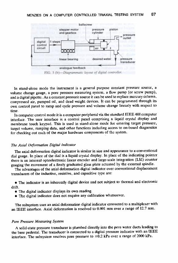
The principles of operation are shown in the schematic diagram in Fig. 5b. Deaeratedwater in a cylinder is pressurized and displaced by a piston moving in the cylinder. Thepiston is actuated by a ball screw turned in a captive ball nut by a stepping motor andgearbox that move rectilinearly on a ball slide.
Pressure is detected by means of an integral solid state pressure transducer. Controlalgorithms are built into the programmable memory to cause the controller to seek to atarget pressure or step to a target volume change. Volume change is measured by countingthe steps of the stepping motor. Knowing the number of steps per revolution of the motor ,the gearbox ratio, and the pitch of the ball screw, the bore of the pressure cylinder may befound such that one step of the motor equals 1 mm3.
FIG. 5 (a)-Digital controller.
87MENZIES ON A COMPUTER CONTROLLED TRIAXIAL TESTING SYSTEM
In stand-alone mode the instrument is a general purpose constant pressure source, avolume change gauge, a pore pressure measuring system, a flow pump (or screw pump),and a digital pipette. As a constant pressure source it can be used to replace mercury column,compressed air, pumped oil, and dead weight devices. It can be programmed through itsown control panel to ramp and cycle pressure and volume change linearly with respect to
time.In computer control mode it is a computer peripheral via the standard IEEE 488 computer
interface. The user interface is a control panel comprising a liquid crystal display andmembrane touch keypad. This is used in stand-alone mode for entering target pressure,target volume, ramping data, and other functions including access to on-board diagnosticsfor checking out each of the major hardware components of the system.
The Axial Deformation Digital Indicator
The axial deformation digital indicator is similar in size and appearance to a conventionaldial gauge. In place of the dial is a liquid crystal display. In place of the indicating pointerthere is an internal optoelectronic linear encoder and large-scale integration (LSI) countergauging the movement of a finely graduated glass plate actuated by the external spindle.
The advantages of the axial deformation digital indicator over conventional displacementtransducers of the inductive, resistive, and capacitive type are:
.The indicator is an inherently digital device and not subject to thermal and electronic
drift-.The digital indicator displays its own reading..The digital indicator does not require any calibration whatsoever .
The subsystem uses an axial deformation digital indicator connected to a multiplexer withan IEEE interface. Axial deformation is resolved to 0.001 mm over a range of 12.7 mm.
Pore Pressure Measuring System
A solid-state pressure transducer is plumbed directly into the pore water ducts leading tothe base pedestal. The transducer is connected to a digital pressure indicator with an IEEEinterface. The subsystem resolves pore pressure to :f:0.2 kPa over a range of 2000 kPa.

88 ADVANCED TRIAXIAL TESTING OF SOIL AND ROCK
System Operation
Test Control
Continuously and at a frequency typically less than once a second, the computer:
.takes a set of readings from the digital controllers and the axial deformation and porepressure measuring subsystems,
.calculates the current test parameters and stores them as required, and
.gives new commands to the digital controllers to keep the selected test on the chosenstress path or strain path.
Using this general approach in a series of standard subroutines, a range of tests can bemade available by selection from a test menu.
Test Menu
The test menu of the system is as follows:
.saturation by simultaneous ramps of cell pressure and back pressure;
.incremental and ramped evaluation of pore pressure parameter B ;
.isotropic and anisotropic consolidation;
.unconsolidated-undrained compression/extension;
.consolidated-undrained compression/extension with pore pressure measurement;
.consolidated-drained compression/extension, volume change resolved to 1 mm3;
.Ko consolidation and swelling for saturated soils~
.continuous linear stress paths, mixed drained and undrained, mixed compression andextension ;
.cyclic loading by axial stress controlled square, sinusoidal, and triangular wave forms;periods down to sea wave periods; and
.permeability by constant hydraulic gradient or by constant rate of flow [6].
The system has a "loop-round" facility enabling any series of the above tests to besequentially carried out on the one test specimen with changed height and diameter beingpassed on from the end of one test to the beginning of the other, for example, unconsolidated-undrained after Ko gives a SHANSEP capability.
Test Control Algorithms
The on-board intelligence of the digital controller provides useful functions (seek to targetpressure, step to target volume change, ramp pressure, ramp volume change) which facilitatethe design of the test control algorithms. Generally, for tests most simply described by astress path, the controllers are continually set and reset to ramped pressure control (for astress path test per se, this refers to the axial and radial stress controllers). For tests mostsimply described by a strain path (for example, a U-U test) the controllers are continuallyset and reset to ramped volume change control (for the U-U test this would be the axialcontroller only). There are two notable exceptions to this approach-Ko consolidation andswelling, and automatic drained testing rate by controlled hydraulic gradient, as discussedbelow.

89MENZIES ON A COMPUTER CONTROLLED TRIAXIAL TESTING SYSTEM
Ko Consolidation and Swelling
Here the test control rule is that the volume change in the pore water duct must at alltimes be equal to the volume of the axial deformation times the original average cross-sectional area. This rule is only applicable to saturated soils. Continuously, and at a frequencytypically less than once a second, the computer:
.calculates the volume of the axial deformation times the original average cross-sectionalarea;
.commands the back-pressure controller (which is under volume change control) to stepan equal and opposite volume change, that is, extract pore water if consolidation is required,infuse water if swelling is required; and
.commands the cell pressure controller to adjust cell pressure to keep the back pressureconstant at the predetermined value.
The test is only valid if the chosen testing rate is such that unacceptable excess porepressures do not develop (for example, during consolidation, it is possible to imagine con-traction of the test specimen adjacent to the base porous stone while bulging occurs in themiddle third of the test specimen). Accordingly, it is highly desirable to regulate the testingrate by controlling the hydraulic gradient throughout the height of the test specimen asdiscussed in the following section.
Automatic Drained Testing Rate
One of the biggest problems associated with any form of triaxial testing is the questionof testing rate. This is particularly so in effective stress testing, that is, testing where acomplete knowledge of the pore water pressure regime is required.
For the particular case of drained tests (conventional, stress path, Ko) where a constantback pressure is applied to the base pedestal or to the top cap, if the testing rate is too highthe back pressure may be significantly different from the average pore pressure throughoutthe test specimen. Accordingly, chosen testing rates tend to err on the side of caution and,in many cases, are far too low. This slows down test throughput and reduces productivity.
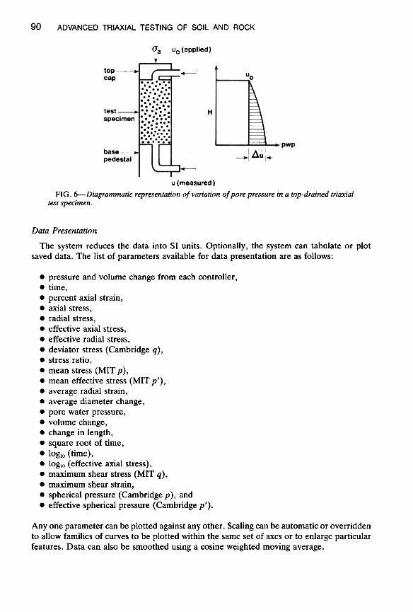
An alternative is to measure the difference in pore pressure from one end of the testspecimen to the other and to control the testing rate to restrict the difference to an acceptablelevel. As shown in the schematic diagram in Fig. 6, the system applies a constant backpressure to the top drain and measures the pore pressure at the base pedestal. Axial loadingcan now be controlled such that the difference in end pore pressures-the excess porepressure-is either a fixed value, say 5 kPa, or, more logically perhaps, a fixed proportionof axial total stress, say 5%. Referring to Fig. 6, these control criteria may be expressedalgebraically as
Uo = ~u = 5 kPa (2)u
or
6.u/O". = 5% (3)
In this way the soil is tested at the optimum testing rate for the chosen criteria, auto-matically adjusting to changing soil conditions such as permeability, while the state ofeffective stress is continuously controlled and measured.
90 ADVANCED TRIAXIAL TESTING OF SOIL AND ROCK
(Ja Uo (applied)
u(measured)
FIG. 6- Diagrammatic representation of variation of pore pressure in a top-drained triaxial
test specimen.
Data Presentation
The system reduces the data into SI units. Optionally, the system can tabulate or plotsaved data. The list of parameters available for data presentation are as follows:
.pressure and volume change from each controller ,
.time,
.percent axial strain,
.axial stress,
.radial stress,
.effective axial stress,
.effective radial stress,
.deviator stress (Cambridge q),
.stress ratio,
.mean stress (MIT p) ,
.mean effective stress (MIT p'),
.average radial strain,
.average diameter change,
.pore water pressure,
.volume change,
.change in length,
.square root of time,
.loglo (time),
.loglo (effective axial stress),
.maximum shear stress (MIT q),
.maximum shear strain,
.spherical pressure (Cambridge p), and
.effective spherical pressure (Cambridge p').
Anyone parameter can be plotted against any other. Scaling can be automatic or overriddento allow families of curves to be plotted within the same set of axes or to enlarge particularfeatures. Data can also be smoothed using a cosine weighted moving average.

91MENZIES ON A COMPUTER CONTROLLED TRIAXIAL TESTING SYSTEM
System Performance
For an assessment of the performance of the system, reference can be made to Coatsworthand Hobbs [2] who carried out advanced tests to provide design parameters for a varietyof construction projects. Their tests are summarized below.
Stress Path Testing
In situ ground deformation parameters were required for predicting the movement of aproposed immersed tube tunnel river crossing in Wales. Stress path tests were carried outon selected piston samples of glacial lake clays from beneath the proposed tunnel. As shownin Fig. 7, each test specimen was consolidated under a small all-round stress (point A inFig. 7) to give it some stability. The specimen was then Ko consolidated to the maximum
0 200 400 600 800 1000
pkPa
Ko consolidation
Drained stress path
A-BB-C
C-D
D-E
Undrained unloading
Swelling
Representinggeological history
Representingexcavation of the trench
E-FF-GG-HH-II-JJ-K
Undrained loadingConsolidationUndrained loadingConsolidationUndrained loadingConsolidation
Representingthe placingof theimmersedtubetunnel
K-L Undrained compressionto failure
To determine the soilstrength after construction
FIG. 7-Stress path test on glacial clay (from Coatsworth and Hobbs [2]).

92 ADVANCED TRIAXIAL TESTING OF SOIL AND ROCK
previous consolidation pressure (stage A-B in Fig. 7). The final stage in the reimpositionof the in situ stresses was to impose a drained stress path while allowing swelling to occur(stage B-C). The specimen was then subjected to undrained unloading to simulate excavation(stage C-D). Drainage was then allowed to occur at constant total stresses (stage D-E).The increments in vertical stress corresponding to tunnel construction were applied in anumber of undrained stages, usually three (E-F, G-H, 1-1), each undrained stage beingfollowed by a drainage interval (F-G, H-I, l-K) during which the total stresses were main-tained constant.
These tests provided deformation moduli significantly different from those obtained fromconventional oedometer tests, even allowing for Skernpton and Bjerrum's [7] correction, ageneral conclusion also reached by Simmons and Sofi [8] who tested London clay.
Cyclic Loading Tests
A series of tests were performed to model the behavior of normally consolidated sandbelow the center of a foundation subjected to repeated loading. The breadth of the foun-dation was large compared to the depth of sand, and so conditions of zero lateral strainwere assumed. As shown in Fig. 8, the loading sequence to model conditions below thefoundation were simplified into three stages, zero lateral strain conditions being maintainedfor both loading and unloading paths, as follows:
.initial consolidation of the sand under effective vertical overburden pressure,
.application of the dead load of the structure and application and removal of the proofload, and
.repeated application and removal of the live load during operational life of the structure.
The tests were carried out on samples of gravelly medium and coarse sand from MonkeyIsland, Bray, Berkshire, England. For clarity, the results given in Fig. 8 are for selectedcycle numbers only. The control algorithm was written by the authors.
150 r
0 50 100 150 200 250
(Ja' kPa
FIG. 8-Cyclic loading test on dense sand (from Coatsworth and Hobbs [2])

MENZIES ON A COMPUTER CONTROLLED TRIAXIAL TESTING SYSTEM 93
Extension Tests
A series of consolidated-undrained extension tests were carried out on overconsolidatedsilty clay to investigate the stability of the base of a deep excavation in the Middle East.The results of 1 set of tests on a stiff to very stiff silty clay overconsolidated by desiccationare given in Fig. 9 in which the strain contours show the mobilization of strength. In all, 24tests were completed in 48 days with just 1 cell.
System Features
Some major features of the system are summarized below
Cell
.Specifically designed to facilitate stress path testing
.Ram friction negligible and corrected for by computer anyway
.Plane top cap reduces bedding and alignment errors
Digital Controllers
.Pressure measured to 0.2 kPa, pressure controlled to 0.5 kPa
.Volume change measured and controlled to 1 mmJ
.On-board intelligence enables ramping of pressure and volume change
Software
.Repeatability of tests
.Automatic data recording, data reduction, and data presentation to standard format
.Advanced tests can be carried out as routinely as conventional tests
p' kPa
0 100 200 300 400 500
.100-Y2%"
q kPa straincontours
-2002%
-300 L
FIG. 9-Undrained extension tests on overconsolidated silty clay (from Coatsworth andHobbs [2]).

94 ADVANCED TRIAXIAL TESTING OF SOIL AND ROCK
Changing the triaxial cell for a hydraulic consolidation cell of the Rowe and Barden type[9] and changing the software package converts the system into a computer controlledconsolidation testing system. The test menu includes classic step loading, constant rate ofdeformation, constant rate of loading, controlled hydraulic gradient, and permeability byconstant rate of flow.
Because it is software based, the system repertoire may readily be updated to incorporatenew techniques (for example, strain path testing) without changes in hardware. At the timeof writing, over 50 systems are currently in use worldwide with the users providing aninvaluable data bank of experience and suggestions. This feedback is reflected in periodicreleases of software enhancements.
Acknowledgments
The author thanks the editor of Ground Engineering and the directors of Soil MechanicsLtd. for their permission to reproduce Figs. 7, 8, and 9.
References
[1] Menzies, B. K., "Soil Testing System," Geotechnical News, Vol. 1, No.3, 1984, pp. 38-39.[2] Coatsworth, A. M. and Hobbs, N. B., "Computer Controlled Triaxial Soil Testing Equipment in
a Commercial Laboratory ," Ground Engineering, Vol. 17, No.7, 1984, pp. 19-23.[3] Linenberger, M. J., "Microcomputer Controlled Cyclic Triaxial Testing System," Project Report
NSF83-297p for Master of Science Degree, University of Massachusetts-Amherst, 1983.[4] Hsieh, K. H., "Techniques for Investigation of Sand Behaviour Under Cyclic Loading," Project
Report OUR85-321p for Master of Science Degree, University of Massachusetts-:Arnherst, 1985.[5] Bishop, A. W. and Wesley, L. D., "A Hydraulic Triaxial Apparatus for Controlled Stress Path
Testing," Geotechnique, Vol. 25, No.4, 1975, pp. 657-670.[6] Olsen, H. W., Nichols, R. W. and Rice, T. L., "Low Gradient Permeability Measurements in a
Triaxial System," Geotechnique, Vol. 35, No.2, 1985, pp. 145-157.[7] Skernpton, A. W. and Bjerrum, L., "A Contribution to the Analysis of Foundations on Clay,"
Geotechnique, Vol. 7, No.4, 1957, pp. 168-178.[8] Simmons, N. E. and Som, N. N., "Settlement of Structures on Clay with Particular Emphasis on
London Clay," Report 22, ClRIA, London, 1970.[9] Rowe, P. W. and Harden, L., "A New Consolidation Cell," Geotechnique, Vol. 16, No.2, 1966,
pp. 162-170.