a comparative study on t girder bridge deck using grillage
TRANSCRIPT

A Comparative Study on T Girder Bridge Deck
using Grillage Analogy and Finite Element
Method
Gaurav Somani 1 1P.G. Student, Mewar University,
Chittorgarh, Rajasthan, India
Abstract - Concrete slabs and t- girder bridges have been the
dominant bridges in India. Especially in recent years, many road
constructions are underway, some are under construction, and
some road projects are planned to be carried out in the future. As
the project becomes larger, it is necessary to improve the design
method and make it more effective every day. It summarizes the
requirements of the new bridge and the important features of the
planned site and makes it the basis for each design. Initially, the
dimensions of the structural members were chosen according to
the designer's experience, and at a later stage, the engineering
software was used to compare the alternative software and
optimize the part size. Finally, a complete analysis and analysis of
all important construction phases and detailed shop drawings will
be carried out.
Key Words: Skewed bridges, bending stress, shear stress
1. INTRODUCTION
The bridge is a structure that can access the barrier without
closing the barrier. The necessary accesses are roads, railways,
pedestrians, pipes or canals. The obstacle to overcome may be
a river, a road, a railroad or a valley. From the engineering point
of view, the bridge can be described as plain (or right) or
sloping. A typical bridge is a bridge with a vertical axis
perpendicular to the platform pillar. Further, in a conventional
bridge, the deck and the support beam are disposed
symmetrically with respect to the center of the bridge, and the
center line is the same as the longitudinal axis thereof. This
arrangement is ideal and ideal. Because bridge analysis and
construction are simplified, leading to an economical structure.
To analyze this, it is necessary to divide the superstructure of
the bridge into smaller, more manageable components
consisting of rays, deck panels, barrier systems, sections and
membranes.
It summarizes the requirements of the new bridge and the
important features of the planned site and makes it the basis for
each design. Initially, the dimensions of the structural members
were chosen according to the designer's experience, and at a
later stage, the engineering software was used to compare the
alternative software and optimize the part size. Finally, a
complete analysis and analysis of all important construction
phases and detailed shop drawings will be carried out.
1.1 Main Components of a Bridge
A typical bridge consists of the following components:
a) Deck slab.
b) Cantilever slab portion.
c) Footpaths, if provided, kerb and handrails or crash barriers.
d) Longitudinal girders, considered in design to be of T-section.
e) Cross beams or diaphragms, intermediate and end ones.
f) Wearing coat.
g) Abutments and piers.
h) Foundation (pile cap and piles).
1.2 Type of Bridge Decks
(a) Slab Bridges
Figure 1.1: Typical Cross-section of solid slab deck
(b) Box Girder bridges
Figure 1.2: Typical Cross-Section of box Girder Bridge
(c) T-Beam Bridges
Figure 1.3: Typical Cross-section of T-girder for two lane traffic
1.4 Objective of the Study
A relative investigation of T-Beam arrangement of deck piece
with various IRC loadings considered for the examination. FEM
investigation is finished utilizing STAAD Pro. V8i In this
investigation, the destinations are accomplished by basic
grouping:
International Journal of Engineering Research & Technology (IJERT)
ISSN: 2278-0181http://www.ijert.org
IJERTV10IS060034(This work is licensed under a Creative Commons Attribution 4.0 International License.)
Published by :
www.ijert.org
Vol. 10 Issue 06, June-2021
85

• To set up and exhibit a helpful, solid, and precise
philosophy for dissecting solid structures with specific
accentuation on T-Girder solid extension decks
• Approving FEM Analysis and looking at grillage similarity
Method of examination for shifting lengths.
• To propose which model can give more efficient plan.
• Performing FEM and GA Analysis on T-pillar arrangement
by considering greatest Shear compel, most extreme
twisting minute and most extreme torsional snapshots of
parameters of correlation
2. LITERATURE REVIEW
The essential target of this examination was to set up and exhibit
an advantageous, solid, and exact technique for breaking down
fortified solid structures with specific accentuation on
strengthened solid extension decks. An optional target was to
build up a capacity for foreseeing anxiety dispersion through the
thickness of fortified solid scaffold decks. Such data isn't
effortlessly gotten through experimentation. The extension has
broken down for single traverse with length changing from
12m,15m and 18m and twofold path width subjected to various
IRC stacking design class An and 70R . The aggregate length of
the extension Deck framework is made of cast in situ T molded
cement longitudinal braces and cross supports. The extension is
straight and has no skew. The standard extension models are
created. The outcomes are acquired regarding examination of
various parameters.
Menessa (2007) this examination work led FEA for just upheld,
one-traverse, multi-path fortified solid piece spans. Four
traverse lengths were considered in this parametric examination
as 7.2, 10.8, 13.8, and 16.2 m with comparing chunk thickness
of 450, 525, 600 and 675 mm separately. The outcomes were
contrasted and straight scaffolds. SAP2000 was utilized to
produce three-dimensional (3D) limited component models.
Qaqish et al (2008) In this exploration a straightforward
traverse T-beam connect pivoted toward one side and opposite
end sliding the longitudinal way was broke down by utilizing
AASHTO particulars and stacking as a one dimensional
structure, at that point a three-dimensional structure was
completed by utilizing limited component plate for the deck
section and shaft components for the principle pillar. The two
models were subjected to AASHTO Loadings and at specific
areas to create greatest bowing minute and most extreme shear.
The outcomes were broke down and it was discovered that the
outcomes got from the limited component demonstrate are littler
than the outcomes acquired from one dimensional examination,
which implies that the outcomes got from AASHTO loadings
are moderate.
Shreedhar, et al (2012) a straightforward traverse T-beam
connect was examined by utilizing I.R.C. particulars and
stacking (dead load and live load) as a one dimensional
structure. A similar T-bar Bridge was dissected as a three-
dimensional structure utilizing limited component plate for the
deck section and shaft components for the fundamental bar
utilizing programming STAAD ProV8i. By contributing certain
qualities for traverse, clear roadway width, cross brace interims
and plate thickness. The two models were subjected to I.R.C.
Stacking (Class AA and Class A) to deliver greatest twisting
minute. The outcomes were broke down and it was discovered
that the outcomes got from the limited component demonstrate
were lesser than the outcomes acquired from one dimensional
examination, which implies that the outcomes got from I.R.C.
loadings are traditionalist and FEM gives sparing outline.
Khatri, et al (2012) their study led on grillage similarity
technique for investigation of extensions. A sum of nine
distinctive matrix sizes (4 to 12 divisions) are made utilizing
grillage relationship with various skew edges 30°, 45° and 60°
to decide the best lattice estimate. It is watched that FEM and
Grillage strategy comes about are not comparative for each
framework estimate contingent upon different parameters.
Variety in response esteem is same in FEM and Grillage strategy
however variety of B.M and torsion in FEM is lower than
grillage comes about.
Samuel (2016) in his thesis endeavored to examine the
consequences of T Girder superstructure utilizing both the
estimated strategy which depends on the conveyance factor idea
and grillage similarity technique. Both these strategies were
utilized to break down RCC T and box brace superstructure and
comparing to change in rush hour gridlock paths, traverse length
and stomach (for e.g,: 10.3 m width and 20 m traverse) and
valuable data was acquired with respect to the variety of bowing
minute and shear constrain. It was presumed that outcomes got
from grillage similarity strategy were littler than rough
technique aside from shear power of inside brace of T-Girder
connect.
Arun L (2018) Grillage analogy is probably one of the most
popular computer-aided analysis for analyzing bridge decks.
The method consists of representing the actual decking system
of the bridge by an equivalent grillage of beams. The dispersed
bending and torsional stiffness of the decking system are
assumed, for the purpose of analysis, to be concentrated in these
beams. The actual deck loading is replaced by an equivalent
nodal loading. The requirement of analysis is the evaluation of
internal member forces, stresses and deformations of structures.
After the analysis, distribution of member forces will be
ascertained.
3. METHODOLOGY AND MODELLING OF T-GIRDER
BRIDGE DECK
Numerous exploratory and scientific works has been finished by
numerous analysts in the zone of limited component displaying
and nonlinear FE analysis of RC bridges. Moreover, much
research has been directed concerning the general utilization of
PCs to strengthened cement. STAAD. Pro is a generally utilized
basic examination program fit for breaking down several
auxiliary individuals under various stacking conditions. It
includes a cutting edge UI, representation instruments, intense
investigation and outline motors with cutting edge limited
component and dynamic examination abilities. From display
age, investigation and configuration to perception and result
confirmation, STAAD.Pro V8i is the expert's decision for steel,
solid, timber, aluminum and cool framed steel outline of low and
tall structures, courses, petrochemical plants, burrows,
extensions, heaps and considerably more.
International Journal of Engineering Research & Technology (IJERT)
ISSN: 2278-0181http://www.ijert.org
IJERTV10IS060034(This work is licensed under a Creative Commons Attribution 4.0 International License.)
Published by :
www.ijert.org
Vol. 10 Issue 06, June-2021
86
3.1 Refined Methods of Analysis
Refined strategies for examination for dissecting roadway
connect superstructures and deciding brace minutes and burdens
can be characterized into following classifications:
1. The orthotropic plate approach romanticizes the real
extension structure as a proportionate orthotropic plate,
which is then treated by established hypothesis. This
approach was first created by Guyon for grillages with
insignificant torsional solidness and later for isotropic
chunks. Massonnet expanded this approach by including
the impacts of torsion. The joined work of Guyon and
Massonnet, alluded to as the Guyon-Massonnet stack
conveyance hypothesis, has been stretched out by others.
2. The harmonic analysis procedure, created in the 1950's
by Hendry and Jaeger, considers an indistinguishable
flexural and torsional rigidities from the orthotropic plate
examination, yet dismisses the torsional unbending nature
the transverse way. Burdens are disseminated to the
individual braces just as the section were a constant shaft
over non avoiding bolsters. The stacking is communicated
as a consonant arrangement or Fourier sine arrangement.
Articulations for shear, minute, incline, and redirection are
found by progressive mix of this heap arrangement.
Support twisting minutes are controlled by thinking about
the above arrangement in conjunction with transverse
power balance and incline diversion articulations the
transverse way.
3. The grillage analogy method idealizes the bridge structure
using an equivalent grid system, which is then analyzed by:
Slope-deflection and compatibility equations;
Moment or torque distribution;
Shear distribution;
Reaction distribution
This method usually involves the solution of a large number
of simultaneous equations or numerous arithmetic
calculations.
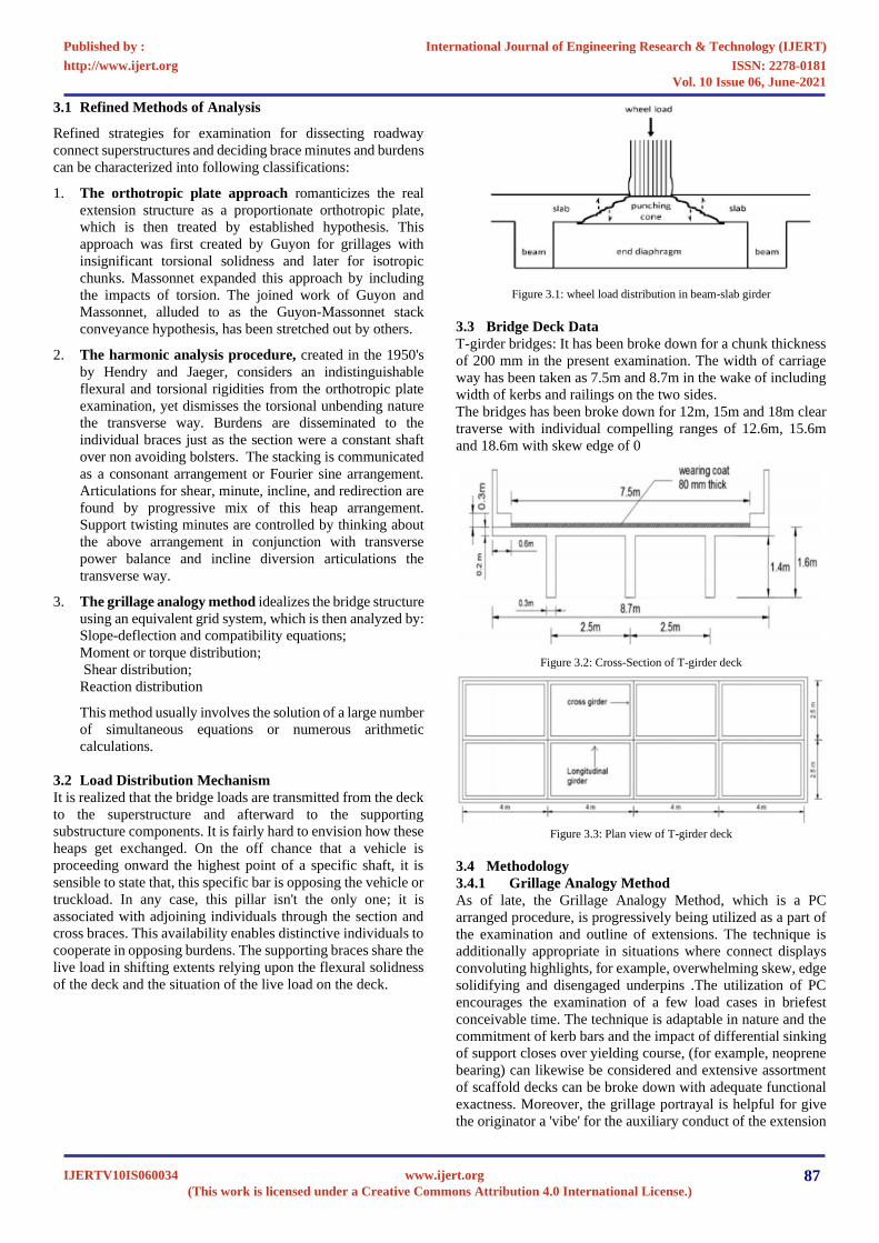
3.2 Load Distribution Mechanism
It is realized that the bridge loads are transmitted from the deck
to the superstructure and afterward to the supporting
substructure components. It is fairly hard to envision how these
heaps get exchanged. On the off chance that a vehicle is
proceeding onward the highest point of a specific shaft, it is
sensible to state that, this specific bar is opposing the vehicle or
truckload. In any case, this pillar isn't the only one; it is
associated with adjoining individuals through the section and
cross braces. This availability enables distinctive individuals to
cooperate in opposing burdens. The supporting braces share the
live load in shifting extents relying upon the flexural solidness
of the deck and the situation of the live load on the deck.
Figure 3.1: wheel load distribution in beam-slab girder
3.3 Bridge Deck Data
T-girder bridges: It has been broke down for a chunk thickness
of 200 mm in the present examination. The width of carriage
way has been taken as 7.5m and 8.7m in the wake of including
width of kerbs and railings on the two sides.
The bridges has been broke down for 12m, 15m and 18m clear
traverse with individual compelling ranges of 12.6m, 15.6m
and 18.6m with skew edge of 0
Figure 3.2: Cross-Section of T-girder deck
Figure 3.3: Plan view of T-girder deck
3.4 Methodology
3.4.1 Grillage Analogy Method
As of late, the Grillage Analogy Method, which is a PC
arranged procedure, is progressively being utilized as a part of
the examination and outline of extensions. The technique is
additionally appropriate in situations where connect displays
convoluting highlights, for example, overwhelming skew, edge
solidifying and disengaged underpins .The utilization of PC
encourages the examination of a few load cases in briefest
conceivable time. The technique is adaptable in nature and the
commitment of kerb bars and the impact of differential sinking
of support closes over yielding course, (for example, neoprene
bearing) can likewise be considered and extensive assortment
of scaffold decks can be broke down with adequate functional
exactness. Moreover, the grillage portrayal is helpful for give
the originator a 'vibe' for the auxiliary conduct of the extension
International Journal of Engineering Research & Technology (IJERT)
ISSN: 2278-0181http://www.ijert.org
IJERTV10IS060034(This work is licensed under a Creative Commons Attribution 4.0 International License.)
Published by :
www.ijert.org
Vol. 10 Issue 06, June-2021
87

and the way in which the scaffold loadings are disseminated
and in the long run taken to the backings.
3.4.1.1 Idealization of Physical Deck into Equivalent
Grillage
The strategy for grillage investigation includes the glorification
of the extension deck as a plane grillage of discrete between
associated shafts. This is the primary vital advance to be taken
by the creator and requirements most extreme care and under-
remaining of the basic conduct of the scaffold decks. It is hard
to make exact general standards for picking a grillage work and
much relies on the idea of the deck to be dissected, its help
conditions, exactness required, quantum of processing office
accessible and so on and just an arrangement of rules can be
proposed for setting matrix lines. It might be noticed that such
admiration of the deck isn't without traps and the framework
lines embraced in one case may not be effective in another
comparable case and the experience and judgment of the
planner will dependably assume a noteworthy part.
3.4.1.2 General Guidelines for Grillage Layout
In view of the gigantic assortment of deck shapes and bolster
conditions, it is hard to embrace immovable tenets for picking
a grillage spread out of the genuine structure. In any case, some
fundamental rules with respect to the area, heading, number,
separating and so on of the longitudinal and transverse
framework lines shaping the glorified grillage work, are
depicted here. Be that as it may, each kind of deck has its own
exceptional highlights and may require some specific game
plans for setting admired framework lines and along these lines
grillage glorification of section needs most extreme care.
3.4.1.3 General Guidelines for Grillage Layout
In view of the gigantic assortment of deck shapes and bolster
conditions, it is hard to embrace immovable tenets for picking
a grillage spread out of the genuine structure. In any case, some
fundamental rules with respect to the area, heading, number,
separating and so on of the longitudinal and transverse
framework lines shaping the glorified grillage work, are
depicted here. Be that as it may, each kind of deck has its own
exceptional highlights and may require some specific game
plans for setting admired framework lines and along these lines
grillage glorification of section needs most extreme care.
3.4.2 Grillage Mesh for T-Girder Bridge
The sensible decision of longitudinal lattice lines for T-beam
bridge decks is to make them incidental with the middle lines
of physical girders and these longitudinal girders are given the
properties of the supports in addition to the related slab of the
piece, which they speak to. Extra lattice lines between physical
girders may likewise be set so as to enhance the exactness of
the outcome. Edge gridlines might be given at the edges of the
deck or at appropriate separation from the edge.
At the point when middle of the road cross supports exist in the
genuine deck, the transverse framework lines speak to the
properties of the cross braces and related deck sections. The
grid lines are set in along the inside lines of cross supports. Grid
lines are likewise set in the middle of these transverse physical
cross girders, if in the wake of considering the successful rib
width of these supports, bits of the slab are forgotten. A
commonplace T-beam bridge with grillage layout is appeared
in Figure 3.4.
Figure 3.4(a): (a) Plan and (c) cross-section of T-Girder Bridge
Figure 3.4(b): (b) longitudinal section and (d) grillage layout
3.4.3 Evaluation of Equivalent Elastic Properties
After the real extension structure is reenacted into equal
grillage, comprising of longitudinal and transverse matrix lines
meeting at discrete hubs, the second imperative advance in
grillage relationship technique is to allocate suitable versatile
properties i.e. flexural and torsional firmness' to every
individual from the grillage so admired. This needs the
calculation of proportionate flexural snapshot of inactivity I
and torsional idleness J for the\ individuals from the grillage
work. This is refined by considering secluded segments of the
deck as though they are singular shafts and the idleness’s are
ascertained for each area and designated to the comparing
grillage bars speaking to that segment.
3.4.3.1 Flexural and Torsional Inertias of Grillage
Members for T-Girder bridges:
Slab-on-girders bridge decks comprise of various beams
spreading over longitudinally between projections with a thin
piece traversing transversely over the best. T- beam bridges are
the normal cases under this classification. The beams might be
thrown solidly with the section or the precast beams with in-
situ slab might be utilized. The decks might be with or without
middle of the road or potentially end stomachs. With the end
goal of estimation of flexural and torsional dormancies, the
powerful width of piece, to work as the pressure spine of T-
beam or L-beam, is required. A thorough investigation for its
assurance is greatly unpredictable and without more exact
methodology for its assessment, IRC proposals are taken after.
International Journal of Engineering Research & Technology (IJERT)
ISSN: 2278-0181http://www.ijert.org
IJERTV10IS060034(This work is licensed under a Creative Commons Attribution 4.0 International License.)
Published by :
www.ijert.org
Vol. 10 Issue 06, June-2021
88

Figure 3.5: Sub-division of T-section
3.4.4 Application and Transfer of Loads to Various Nodes
of Grillage
The bridge deck has been changed into an equal grillage
comprising of longitudinal and transverse framework
individuals with the end goal that the romanticized grillage is
near the physical deck. Every individual from the grillage is
apportioned flexural and torsional latencies which are
proportional to the relating physical properties of the bridge
deck. The longitudinal and transverse matrix lines shape a work
having number of hubs. The scaffold is basically subjected to
vertical burdens containing dead, live and affect loads. Grillage
examination requires that these connected burdens be changed
into equal burdens at hubs.
3.4.5 Design Constants
The various constants used in the analysis of bridge decks are
given below:
Grade of Concrete = M30
Modulus of Elasticity, Ec =3.05×10⁷kN/m2 for all members
Density of RCC = 24 kN/m3
Poisson's Ratio = 0.15
Modular Ratio = 10
3.4.6 Finite Element Method
3.4.6.1 Basic theory
The limited component strategy has been a conspicuous
decision for the displaying and investigation of strengthened
solid frameworks for a long time. Limited components have the
one of a kind capacity to fit in with essentially any geometry
that could be physically executed. Along these lines, the limited
component strategy has picked up acknowledgment as a proper
instrument for the examination of level plates, particularly
those with exceptionally sporadic or bizarre geometries where
the immediate outline and equal edge methods are not
substantial. In sporadic chunks, the limited component strategy
can be appeared to precisely explain for the dissemination of
stress where various approximations and suspicions would be
summoned if the yield line or strip plan procedure were
connected. The arrangement approach is construct either with
respect to taking out the differential condition totally (relentless
state issues), or rendering the PDE into an approximating
arrangement of common differential conditions, which are then
numerically incorporated utilizing standard systems. In
illuminating halfway differential conditions, the essential test
is to make a condition that approximates the condition to be
considered, however is numerically steady, implying that
blunders in the info information and middle of the road counts
don't gather and cause the subsequent yield to be pointless. The
Finite Element Method is a decent decision for unraveling
halfway differential conditions over complex areas.
3.4.6.2 The matrix displacement method used in FEM
The matrix relocation technique for investigation is utilized.
The continuum structure is isolated into various sub- regions,
called limited components, which are thought to be
interconnected at the nodal focuses as it were. Inexact
dislodging capacities are expected over each limited
component. Dislodging similarity conditions are fulfilled and
the overseeing harmony conditions that are created are tackled
to yield the obscure nodal relocations. Once the removals are
known, the strains may then be assessed from the strain-
dislodging relations, lastly the anxieties are resolved from the
pressure strain relations.
Figure 3.6: Co-ordinate system of plate element
The slab of the T-beam bridge deck is spoken to by non-
adjusting yet entire rectangular plate bowing components with
three degrees of flexibility for each hub (w, θx, θy) and a cubic
dislodging model, (Fig 3.6). Concentrates by Gallagher
demonstrated that this component is productive and yields
arrangements of satisfactory precision.
Figure 3.7: Co-ordinate system of beam element
3.5 Grillage Modelling of T-Girder Bridge Deck
The grillage displaying and investigation performed in this
examination were finished utilizing a broadly useful basic
examination and configuration program, STAAD. Master V8i
is a business basic examination and configuration program
created by Bentley Solutions Center. The program is accessible
for PC. The examinations in this proposal were performed
utilizing STAAD. Genius Version 2008. In this area illustrative
examination is introduced thinking about 8.7m scaffold width
and 12m, 15m and 18m extension traverse (length) like the
regular segment appeared.
International Journal of Engineering Research & Technology (IJERT)
ISSN: 2278-0181http://www.ijert.org
IJERTV10IS060034(This work is licensed under a Creative Commons Attribution 4.0 International License.)
Published by :
www.ijert.org
Vol. 10 Issue 06, June-2021
89

Figure 3.8(a): grillage geometry of T-girder deck in STAAD Pro V8i
Figure 3.9 (a): IRC Class A initial vehicle position case 1 (Moving Load) in
STAAD.Pro V8i software.
Figure 3.9 (b): IRC Class A Moving load configuration case 2 in STAAD.Pro
V8i Software
Figure 3.9 (c): Definition IRC Class a Moving load configuration in
STAAD.Pro V8i Software.
The last advance is translation of the outcome, the yield
acquired from the examination of grillage comprises of vertical
redirection and X and Z revolution of every hub, shear drive
and torsional snapshot of each shaft component, twisting
minute at the two finishes of each bar component
3.6 Finite Element Modelling of T-Girder Bridge Deck
3.6.1 Modelling of Structure
The piece is demonstrated utilizing a plate component and it is
discretized into limited component work which comprises of
quadrilateral shell components. The shell components speaking
to the section are 0.5m X 0.5m quadrilateral shell components
with four hubs and six degrees of flexibility for each hub. The
chunk has steady length of 12m and consistent width of 8.7m.
This brought about a chunk show with 620 hubs, 732 plates and
3,720 degrees of opportunity. A draw of the limited component
work is appeared in Fig 3.12. These plates have every one of
the qualities as same as the solid piece all in all. These plates
can deal with stresses independently. The flat components
utilized are the standard shaft components.
Figure 3.10: Geometry of the structure showing finite beam and plate element
in STAAD.Pro V8i software.
(a) Showing deck slab with quadrilateral (b) longitudinal
and cross beam girders plate element Figure 3.11: Rendered view of the structure in STAAD.Pro V8i software.
3.7 Loading Data
The following IRC 6:2014 loadings have been considered in
the analysis of the bridge decks:
Dead Load: The dead load took care of by a scaffold part
comprises of its fair share and bits of the heaviness of the
superstructure and any settled burdens upheld by the
individuals regarding super-forced dead load (SIDL).
IRC Class 70R Wheeled loading:
IRC Class70R wheeled loadings is of two types:
i) 70R Bogie loading weighing 400kN through two axles each
weighing 200kN.
ii) 70R train loading weighing 1000kN through seven ales, one
axle of 80kN, two axles of 120kN each and four axles of 170kN
each. The wheeled vehicle is 15.22m long. The dimensions of
the Class 70R wheeled loading vehicle.
International Journal of Engineering Research & Technology (IJERT)
ISSN: 2278-0181http://www.ijert.org
IJERTV10IS060034(This work is licensed under a Creative Commons Attribution 4.0 International License.)
Published by :
www.ijert.org
Vol. 10 Issue 06, June-2021
90
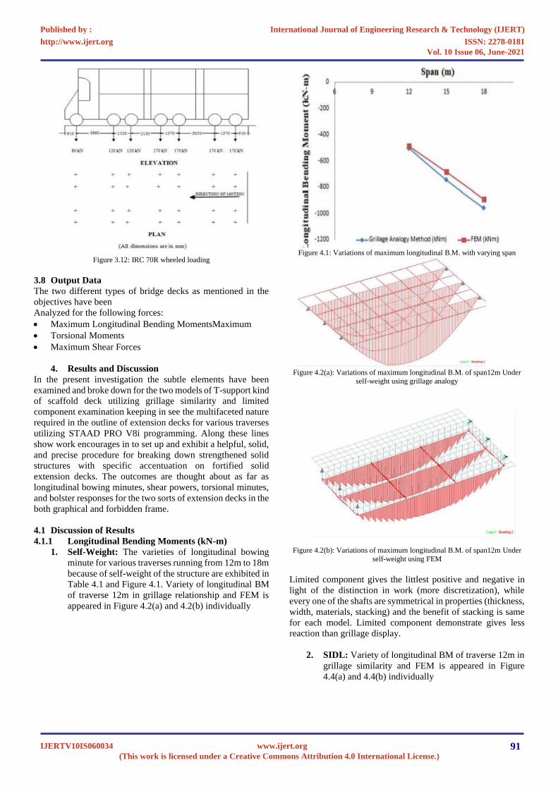
Figure 3.12: IRC 70R wheeled loading
3.8 Output Data
The two different types of bridge decks as mentioned in the
objectives have been
Analyzed for the following forces:
• Maximum Longitudinal Bending MomentsMaximum
• Torsional Moments
• Maximum Shear Forces
4. Results and Discussion
In the present investigation the subtle elements have been
examined and broke down for the two models of T-support kind
of scaffold deck utilizing grillage similarity and limited
component examination keeping in see the multifaceted nature
required in the outline of extension decks for various traverses
utilizing STAAD PRO V8i programming. Along these lines
show work encourages in to set up and exhibit a helpful, solid,
and precise procedure for breaking down strengthened solid
structures with specific accentuation on fortified solid
extension decks. The outcomes are thought about as far as
longitudinal bowing minutes, shear powers, torsional minutes,
and bolster responses for the two sorts of extension decks in the
both graphical and forbidden frame.
4.1 Discussion of Results
4.1.1 Longitudinal Bending Moments (kN-m)
1. Self-Weight: The varieties of longitudinal bowing
minute for various traverses running from 12m to 18m
because of self-weight of the structure are exhibited in
Table 4.1 and Figure 4.1. Variety of longitudinal BM
of traverse 12m in grillage relationship and FEM is
appeared in Figure 4.2(a) and 4.2(b) individually
Figure 4.1: Variations of maximum longitudinal B.M. with varying span
Figure 4.2(a): Variations of maximum longitudinal B.M. of span12m Under
self-weight using grillage analogy
Figure 4.2(b): Variations of maximum longitudinal B.M. of span12m Under
self-weight using FEM
Limited component gives the littlest positive and negative in
light of the distinction in work (more discretization), while
every one of the shafts are symmetrical in properties (thickness,
width, materials, stacking) and the benefit of stacking is same
for each model. Limited component demonstrate gives less
reaction than grillage display.
2. SIDL: Variety of longitudinal BM of traverse 12m in
grillage similarity and FEM is appeared in Figure
4.4(a) and 4.4(b) individually
International Journal of Engineering Research & Technology (IJERT)
ISSN: 2278-0181http://www.ijert.org
IJERTV10IS060034(This work is licensed under a Creative Commons Attribution 4.0 International License.)
Published by :
www.ijert.org
Vol. 10 Issue 06, June-2021
91

Figure 4.3: Variations of maximum longitudinal B.M. (in case of SIDL)
Figure 4.4(a): Variations of maximum longitudinal B.M. of span 12m under
SIDL using grillage analogy
Figure 4.4(b): Variations of maximum longitudinal B.M. of span 12m under
SIDL using FEM
3 Live Load Conditions: The extension deck has been
examined according to IRC 6:2014 rules for two instances
of IRC live loadings i.e. IRC Class 70R wheeled stacking
and IRC Class A stacking.
IRC Class 70R(W) loading: The variety of twisting minute
initiated in connect for IRC Class 70R wheeled stacking
vehicle for various ranges has been exhibited in Table 4.3
and the graphical portrayal of the same has been
introduced in Figure 4.5, Figure 4.6(a) and Figure 4.6(b).
It has been watched that longitudinal twisting minutes
demonstrate an expanding pattern for the live stacking
condition 70R in both FEM and grillage similarity with
increment in traverse.
Figure 4.5: Variations of maximum longitudinal B.M. with varying span (in
case of IRC 70R loading)
Figure 4.6(a): Variations of maximum longitudinal B.M. of span 12m IRC
Class 70R (W) Using grillage analogy
Figure 4.6(b): Variations of maximum longitudinal B.M. of span 12m IRC
Class 70R (W) Using grillage analogy
4. IRC Class A loading: The varieties of plan longitudinal
bowing minute in the extension deck for expanding ranges
under IRC Class A live stacking have been exhibited in
Table 4.4 and Figure 4.7. Variety of longitudinal BM of
traverse 12m in grillage relationship and FEM is appeared
in Figure 4.8(a) and 4.8(b) individually.
International Journal of Engineering Research & Technology (IJERT)
ISSN: 2278-0181http://www.ijert.org
IJERTV10IS060034(This work is licensed under a Creative Commons Attribution 4.0 International License.)
Published by :
www.ijert.org
Vol. 10 Issue 06, June-2021
92
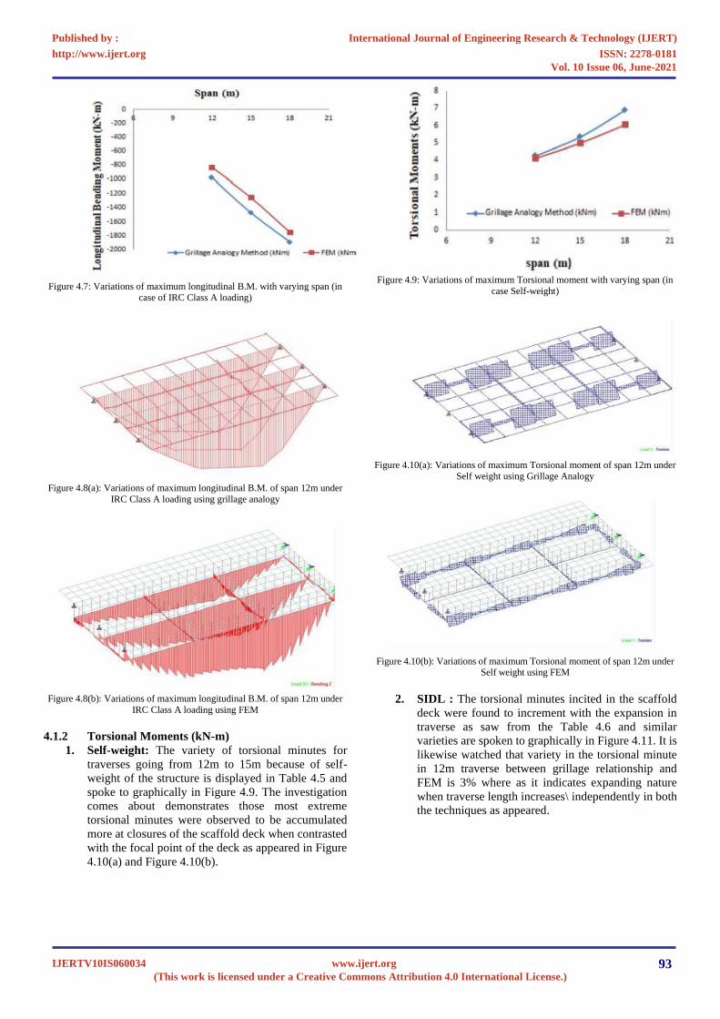
Figure 4.7: Variations of maximum longitudinal B.M. with varying span (in
case of IRC Class A loading)
Figure 4.8(a): Variations of maximum longitudinal B.M. of span 12m under
IRC Class A loading using grillage analogy
Figure 4.8(b): Variations of maximum longitudinal B.M. of span 12m under
IRC Class A loading using FEM
4.1.2 Torsional Moments (kN-m)
1. Self-weight: The variety of torsional minutes for
traverses going from 12m to 15m because of self-
weight of the structure is displayed in Table 4.5 and
spoke to graphically in Figure 4.9. The investigation
comes about demonstrates those most extreme
torsional minutes were observed to be accumulated
more at closures of the scaffold deck when contrasted
with the focal point of the deck as appeared in Figure
4.10(a) and Figure 4.10(b).
Figure 4.9: Variations of maximum Torsional moment with varying span (in
case Self-weight)
Figure 4.10(a): Variations of maximum Torsional moment of span 12m under
Self weight using Grillage Analogy
Figure 4.10(b): Variations of maximum Torsional moment of span 12m under
Self weight using FEM
2. SIDL : The torsional minutes incited in the scaffold
deck were found to increment with the expansion in
traverse as saw from the Table 4.6 and similar
varieties are spoken to graphically in Figure 4.11. It is
likewise watched that variety in the torsional minute
in 12m traverse between grillage relationship and
FEM is 3% where as it indicates expanding nature
when traverse length increases\ independently in both
the techniques as appeared.
International Journal of Engineering Research & Technology (IJERT)
ISSN: 2278-0181http://www.ijert.org
IJERTV10IS060034(This work is licensed under a Creative Commons Attribution 4.0 International License.)
Published by :
www.ijert.org
Vol. 10 Issue 06, June-2021
93

Figure 4.11: Variations of maximum torsional moment with varying span (in
case of SIDL)
Figure 4.12(a): Variations of maximum torsional moment of span 12m under
SIDL Using Grillage Analogy
Figure 4.12(b): Variations of maximum torsional moment of span 12m under
SIDL Using FEM
3. Live load conditions: The extension deck has been
investigated according to IRC 6:2014 rules for two classes of
IRC live loadings-IRC Class 70R haggled Class A stacking.
The investigation comes about are examined underneath:
a) IRC Class 70R(W) loading: The variety of torsional
minutes because of IRC Class 70R stacking case for traverses
extending from 12m to 18m has been exhibited and Figure
4.13. Varieties of most extreme torsional snapshot of traverse
12m under IRC Class 70R (w) utilizing Grillage Analogy and
FEM is appeared in Figure 4.14(a) and Figure 4.14(b)
Figure 4.13: Variations of maximum Torsional Moment with varying span (in
case of IRC 70R loading)
Figure 4.14(a): Variations of maximum Torsional Moment of 12m span under
IRC 70R loading using Grillage Analogy
Figure 4.14(b): Variations of maximum Torsional Moment of 12m span under
IRC70R loading using FEM
b) IRC Class A loading: IRC Class A loading: The torsional
minutes have been found to have more prominent incentive in
grillage similarity technique then FEM with the expansion in
traverse under IRC Class A stacking and the same is spoken to
graphically in Figure 4.15. Varieties of most extreme torsional
snapshot of traverse 12m under IRC Class An utilizing Grillage
Analogy and FEM is appeared in Figure 4.16(a) and Figure
4.16(b)
International Journal of Engineering Research & Technology (IJERT)
ISSN: 2278-0181http://www.ijert.org
IJERTV10IS060034(This work is licensed under a Creative Commons Attribution 4.0 International License.)
Published by :
www.ijert.org
Vol. 10 Issue 06, June-2021
94

Figure 4.15: Variations of maximum Torsional Moment with varying span (in
case of IRC Class A loading)
Figure 4.16(a): Variations of maximum Torsional Moment of 12m span under
IRC Class A loading using Grillage Analogy
Figure 4.16(b): Variations of maximum Torsional Moment of 12m span under
IRC Class A loading using FEM
4.1.3 Shear force (kN)
1. Self-Weight: The variation of maximum shear force
for right spans ranging from 12 m to 18m due to self-
weight of the structure has been presented in Figure
4.17.
Figure 4.17: Variations of shear force with varying span (in case of self-
weight)
Figure 4.18(a): Variations of shear force of 12m span under self-weight using
Grillage Analogy
Figure 4.18(b): Variations of shear force of 12m span under self-weight using
FEM
2. SIDL: The relatively same pattern for the outline shear
powers has been gotten for SIDL case as got on account of self-
weight stacking case, the variety in the consequences of FEM
and Grillage Analogy all the more yet relatively same for
various traverse length, as exhibited in Table 4.10 and
graphically looked at as appeared. Varieties of shear power of
12m traverse under self-weight utilizing Grillage and FEM is
appeared in Figure 4.20(a) and Figure 4.20(b)
International Journal of Engineering Research & Technology (IJERT)
ISSN: 2278-0181http://www.ijert.org
IJERTV10IS060034(This work is licensed under a Creative Commons Attribution 4.0 International License.)
Published by :
www.ijert.org
Vol. 10 Issue 06, June-2021
95

Figure 4.19: Variations of maximum shear force with varying span (in case of
SIDL )
Figure 4.20(a): Variations of maximum shear force of 12m span under SIDL
using Grillage Analogy
3. Live Load Conditions: The extension deck has been
dissected according to IRC 6:2014 rules for two classes of IRC
live loadings-Class 70R wheeled stacking and Class A
stacking. The examination comes about for the two kinds are
talked about underneath:
IRC Class 70R(W) stacking: The most extreme shear powers
have been found to increment with increment in traverse in both
the models under IRC Class 70R wheeled stacking as saw and
the varieties are spoken to graphically in Figure 4.21. Varieties
of shear power of 12m traverse under self-weight utilizing
Grillage and FEM is appeared in Figure 4.22(a) and Figure
4.22(b)
Figure 4.21: Variations of maximum shear force with varying span (in case of
class 70R (W) live loading)
Figure 4.22(a): Variations of maximum shear force of 12m span under class
70R (W)
Live loading using Grillage Analogy
Figure 4.22(b): Variations of maximum shear force of 12m span under class
70R (W) live loading using FEM
a) IRC Class A loading: The greatest shear powers have
been found to increment with increment in traverse in
both the models under IRC Class A stacking and the
varieties are spoken to graphically in Figure 4.23. A
similar rising pattern for this situation likewise has
been seen as on account of the power reactions got
from the use of IRC Class 70R live stacking. .
Varieties of shear power of 12m traverse under self-
weight utilizing Grillage and FEM is appeared in
Figure 4.24(a) and Figure 4.24(b)
Figure 4.23: Variations of maximum shear force with varying span (in case of
IRC
Class A loading)
International Journal of Engineering Research & Technology (IJERT)
ISSN: 2278-0181http://www.ijert.org
IJERTV10IS060034(This work is licensed under a Creative Commons Attribution 4.0 International License.)
Published by :
www.ijert.org
Vol. 10 Issue 06, June-2021
96

Figure 4.24(a): Variations of maximum shear force of 12m span under IRC
Class A
loading using Grillage Analogy
Figure 4.24(b): Variations of maximum shear force of 12m span under IRC
Class A loading using FEM
Thus for all the considered load cases, the shear force tends to
increase with the increase in span ranges also with
methodology. The variations in shear forces in percentage
difference along the span for all the loading cases are as
follows:
Self-weight- in the range of 5% to 8%
SIDL- in the range of 8% to 10%
Live IRC Class 70R wheeled loading- in the range of 5 % to
6.5 %
Live IRC Class A loading- in the range of 10% to 12%
5. CONCLUSIONS
Bridges are a standout amongst the most difficult activity of all
considerate designing works. The number and sizes of scaffolds
have persistently expanded in the previous couple of years.
This has\ required to grow new plan systems. To adapt up to
this request, gigantic endeavors everywhere throughout the
world as dynamic research in the investigation, plan and
development of Bridges are proceeding. The focal point of this
demonstrating is to discover the reason of the outcomes'
disparities of the two models, while the goal of this proposal is
to recreate the conduct of scaffold structure as far as (shear
drive, twisting minute, and torsion) by fluctuating the traverse.
All done by STAAD.Pro V8i programming. In the present
work, it has been watched that more drawn out traverse spans
are one of real worry due to conjusted urban regions and in
addition expanded activity development rate. The parametric
investigation on T-Girder solid extension for differing traverse
length has been led, the parameters like bowing minutes,
torsional minutes and shear powers have been dissected for IRC
Class An and 70R stacking on T-support spans. The near
investigation was directed in light of the expository
demonstrating of just upheld RC T-bar Bridge by grillage
similarity technique and Finite component strategy utilizing
Staad Pro V8i. Based on the examinations, it has been
presumed that:
• Based on this examination grillage relationship technique
gives the moderate outcome with deference BM esteems in
the longitudinal brace when contrasted with limited
component strategy.
• In the instance of T-Girder bridges, it has been watched
that the longitudinal bowing minutes demonstrates a rising
pattern with increment in ranges. In any case, the mid
traverse longitudinal twisting snapshots of the external
girders, were observed to be relatively higher than then the
longitudinal bowing minutes in the center support. The
varieties in rate contrast for right edge straight bridges
between grillage similarity and limited component
technique are found in the scope of 2% to 8 % for dead
load cases and 10% to 14.5% for live load cases, which are
stopped worthy qualities.
In the instance of T-Girder bridges, it has been watched
that the torsional minutes increments with increment in
traverse and furthermore external brace demonstrates more
torsional minute at that point center support. The varieties
in rate contrast between two strategies are found in the
scope of 3% to 12% for dead load cases and 12% to14%
for live load cases.
• In the instance of T-Girder bridges, it has been watched
that the shear compel additionally increments with
increment in ranges. Likewise, it has been discovered that
most extreme shear powers tend to increment close to the
edge backings of the external supports for every one of the
traverses considered in the investigation. The varieties in
rate distinction between the grillage similarity technique
and limited component strategy are found in the scope of
5% to 10% for dead load cases and 5% to 12% for live load
cases.
• When the explanatory outcomes are looked at for IRC
Class 70 R (W) and IRC Class A stacking, it has been
discovered that the plan esteems with IRC Class 70 R (W)
give relatively high reactions and in this way are
represented to be utilized as a part of the outline of the
extensions.
• In conclusion, Finite Element show has more discretization
(more exact), so the plan base of this reaction with the
littler component gives less measure of materials et cetera
(that is the conservative factor), therefore limited
component demonstrate is more temperate outline than
grillage display.
• Maximum BM happens for class 70R wheeled vehicle.
Thus class 70R vehicle case is the most basic case for
greatest BM in longitudinal brace.
• Maximum SF happens for class 70R wheeled vehicle.
Thus class 70R wheeled vehicle case is the most basic case
for greatest Shear compel in longitudinal brace.
6. FUTURE SCOPE
However during the course of this study, it has been found that
there are still some grey areas. In order to find the more details,
further studies can be recommended in the following ways:
• In request to discover the points of interest, the
investigation can be led on more extraordinary kind of
RCC spans and diverse span cases.
• The study can be additionally stretched out to multi-lane
bridges.
International Journal of Engineering Research & Technology (IJERT)
ISSN: 2278-0181http://www.ijert.org
IJERTV10IS060034(This work is licensed under a Creative Commons Attribution 4.0 International License.)
Published by :
www.ijert.org
Vol. 10 Issue 06, June-2021
97

• The study has been led on basically upheld deck chunk. An
examination might be led on consistent deck slabs.
• The study can be additionally stretched out for breaking
down the impact of skew edges by considering stress and
strain parameters.
REFERENCES
[1] Indian Road Congress, IRC: 6-2017. Standard Specifications and Code
of Practice for Road Bridges Section: II- Loads and Stresses, New Delhi,
India.
[2] Indian Road Congress, IRC: 21-2000. Standard Specifications and Code of Practice for Road Bridges, Section III Cement Concrete (Plain and
Reinforced), New Delhi, India.
[3] Indian Road Congress, IRC: 22-1986. Standard Specifications and Code of practice for Road Bridges. Section: VI – Composite Construction, New
Delhi, India.
[4] Indian Road Congress, IRC: 24-2001. Standard Specifications and Code of Practice for Road Bridges, Section: V – Steel Road Bridges, New
Delhi, India.
[5] India Road Congress, IRC: 112 – 2011 Standard Specifications and Code of Practice for Concrete Road Bridges, New Delhi, India
[6] Indian Standard, IS: 808-1989. Dimensions for Hot Rolled Steel Beam,
Column, Channel and Angle Sections, New Delhi, India. [7] Chapman and Balakrishna (1964) Chapman, J. C., & Balakrishnan, S.
(1964). Experiments on composite beams. The Structural
Engineer, 42(11), 369-383. [8] Goble et al. (1992), Upper Limb Asymmetries in the Matching of
Proprioceptive Versus Visual Targets Daniel J. Goble, and Susan H.
Brown [9] Menessa (2007) Influence of Skew Angle on Reinforced Concrete Slab
Bridges March 2007 Journal of Bridge Engineering 12(2)
[10] Gupta et al (2007) Gupta, J. J.; Doley, S.; Bujarbaruah, K. M., 2007. Evaluation of forage based feeding system for rabbit production in
northeastern region of India. Indian J. Anim. Nutr., 24 (4): 216-218
[11] Onyia (2008) Determination of the critical buckling load of shear deformable unified beam ME Onyia, EO Rowland-Lato International
Journal of Engineering and Technology 10 (3), 647-657
[12] Qaqish et al (2008)IJREAT International Journal of Research in
Engineering & Advanced Technology, Volume 1, Issue 2, April-May,
2013 ISSN: 2320 - 8791
Published by: PIONEER RESEARCH & DEVELOPMENT GROUP (www.prdg.org) 1 Comparative Study of the Analysis and Design of T-
Beam Girder and Box Girder Superstructure
Bapat (2009) [13] INFLUENCE OF BRIDGE PARAMETERS ON FINITE ELEMENT
MODELING OF SLAB ON GIRDER BRIDGES. Amey V. Bapat
ABSTRACT The present study is part of the Long Term Bridge Performance Program (LTBP) funded by the Federal Highway
Administration.
Shreedhar, et al (2012) [14] Analysis of T-beam bridge using finite element method R Shreedhar, S
Mamadapur International Journal of Engineering and Innovative
Technology 2 (3), 340-346 [15] Khatri, et al (2012) Vikash Khatri, P. R. Maiti, P. K. Singh,Ansuman Kar,
“Analysis of skew bridges using computational methods”, IJCER, May –
June 2012, vol.2, issue no. 3, PP: 628-636. [16] Jaggerwal et al. (2014) Himanshu Jaggerwal and Yogesh Bajpai,
“Analysis of skew bridges using grillage analogy method”, international journal of engineering & science research Vol-4/Issue-8/463-473,
IJESR/August 2014.
[17] Bhosale, (2013) International Journal of Engineering and Innovative Technology (IJEIT) Volume 2, Issue 7, January 2013 1 Experimental
Study on Connections, By Using Light Gauge Channel Sections and
Packing Plates/Stiffener Plate at the Joints V.M.Vaghe, S.L.Belgaonkar, A.S.Kharade A.S.Bhosale.
[18] Samuel (2016) Redd, Samuel Carey, "Strength, durability, and
application of grouted couplers for integral abutments in accelerated bridge construction projects" (2016). Graduate Theses and Dissertations.
15080.
[19] Arun L (2018) International Research Journal of Engineering and Technology (IRJET) Volume: 05 Issue: 12 Dec 2018 ANALYSIS AND
DESIGN OF BRIDGE DECK USING GRILLAGE METHOD - AS PER
IRC Pooja C, Arun L, Thejashwini
[20] Baidar Bakht The Grillage analogy in bridge analysis Authors: Leslie
G. Jaeger and Baidar Bakht
International Journal of Engineering Research & Technology (IJERT)
ISSN: 2278-0181http://www.ijert.org
IJERTV10IS060034(This work is licensed under a Creative Commons Attribution 4.0 International License.)
Published by :
www.ijert.org
Vol. 10 Issue 06, June-2021
98