a comparative study on channel coding scheme for
TRANSCRIPT

A Comparative Study on Channel Coding Schemefor Underwater Acoustic CommunicationMustafa Sami Ahmed ( [email protected] )
Universiti Tun Hussein Onn Malaysia https://orcid.org/0000-0002-3741-7091Nor Shahida Mohd Shah
Universiti Tun Hussein Onn Malaysia
Research Article
Keywords: Channel coding scheme, underwater acoustic, Convolutional, LDPC, Turbo, Polar, t-distribution
Posted Date: September 13th, 2021
DOI: https://doi.org/10.21203/rs.3.rs-826429/v1
License: This work is licensed under a Creative Commons Attribution 4.0 International License. Read Full License

A comparative study on Channel Coding Scheme for underwater acoustic
communication
Mustafa Sami Ahmed1, Nor Shahida Mohd Shah2 ([email protected]), ([email protected])
1Departmant of Communication Engineering, Faculty of Electrical and Electronic Engineering, Universiti Tun Hussein Onn Malaysia, Parit Raja, Batu Pahat, 86400,
Johor, Malaysia.
Abstract
There are various challenges in underwater acoustic communication (UWA) however
bit error rate (BER) is considered as the main challenge as it significantly affects the
UWA communication. In this paper, different coding schemes such as Convolution,
Turbo, LDPC, and Polar coding based on the t-distribution noise channel are
investigated, and binary phase-shift keying (BPSK) modulation with a code rate of
1/2 has considered in the evaluation and analyses. The evaluation of these channel
coding schemes is performed based on BER, computational complexity as well as
latency. The results have shown the outperform of polar coding in UWA over other
channel coding schemes as it has lower BER and lower computational complexity.
Keywords: Channel coding scheme; underwater acoustic; Convolutional; LDPC;
Turbo; Polar; t-distribution.
1. Introduction
Under water explorations, subsea resource extractions, pollution monitoring, national
defence missions etc. are being critically analysed by underwater acoustic
communications (UWAC) and networking technologies. The applications of UWAC
have attracted increased interests as the oceans are explored as a sustainable source of
food and energy [1], [2],[3]. Communications across shallow seawater channels are
characterized by high multipath, high noise level, strong Doppler and other complex
random transmission features. These complicate underwater communication (UWC)
in terms of reliability and a low data rate compared with wireless communication [4].
Recent research focus on acoustic communications has sought to address
issues such as reliability, latency, and bandwidth efficiency, where adaptation to the
changing propagation conditions is the main focus [2]. In the systems’ designs, the
nature of the acoustic propagation forces trade-offs on the various issues depending

on the requirements. For instance, reliability is a trade-off for a high data rate while
latency is traded for full reliability. Moreover, a low computational complexity is
required to achieve a high-speed data rate system. Thus, in channel coding,
computational complexity and reliability are compromised with respect to each other
depending on the systems’ design. Figure 1 demonstrates the trade-off between
reliability, latency and computational complexity considered in channel coding
techniques. These channel trade-offs and constraints are challenging; however,
acoustic channel exhibit peculiar challenges and solutions. This paper considers a user
requirement channel coding scheme for UWAC system of lengthy message
transmission.
Figure 1: Requirements for the channel schemes for UWAC
In this work, different channel coding schemes, turbo, convolution, LDPC, and
polar codes are considered and evaluated for application in the transmission of
lengthy messages (256< K ≤ 1024 bits) with respect to user requirement of
complexity, BER and latency performance on the t-distribution of noise channel with
Binary phase-shift Keying (BPSK) of code rate 1/2. Next, Section 2 presents the
channel model in UWA while Section 3 describes the channel coding schemes. The
results and analyses are given in Section 4 and finally, 5 concludes the research.

2. Channel model in UWA
Based on the analysis of the field data measurements in a shallow water, a noise
model of the underwater acoustic channel is presented in [5]. The likelihood density
function has been proposed for the noise amplitude distribution and the probability
functions have been derived in [5],[6]. Hence, for binary signalling of the channel, an
expression to the symbol error probability is presented. The noise data collected from
a shallow water was also simulated to show the noise effects on the performance of
binary signalling system of UWAC. In addition, t-distribution was used to show good
fitting of the field measurement analysis of the amplitude of the noise distribution
with average degree of freedom of about 3. Equation (1) expresses the symbol error
probability of the binary UWA noise channel.
2
2
0
2 20.636 1 1b b
BPSK
o o
E EP x dx
N N
(1)
where x is a vector of M discrete amplitude levels of noise, and bo/EN is the energy per
bit to noise power spectral density ratio. Some researchers have indicated that the
noise distribution in shallow water follows the Gaussian distribution while others
assume the noise distribution in UWA is non-white and non-Gaussian [7],[8].
3. Channel coding schemes
In channel coding, redundancies are added to some useful bits to secure the data in a
noisy channel and to reduce transmission errors to the minimum regardless of its
intricacies in communication systems. The main step of the channel coding
procedures is partitioning the coding into several subsets. There are four common
kinds of the channel coding schemes and these are convolutional codes (CC), turbo
codes (TC), polar codes (PC) and low density parity check (LDPC) code [9]. Figure 2
depicts the digital communication system block diagram of the different channel
coding schemes. The most important aspect of channel coding is its ability to provide
the satisfaction for user requirements.
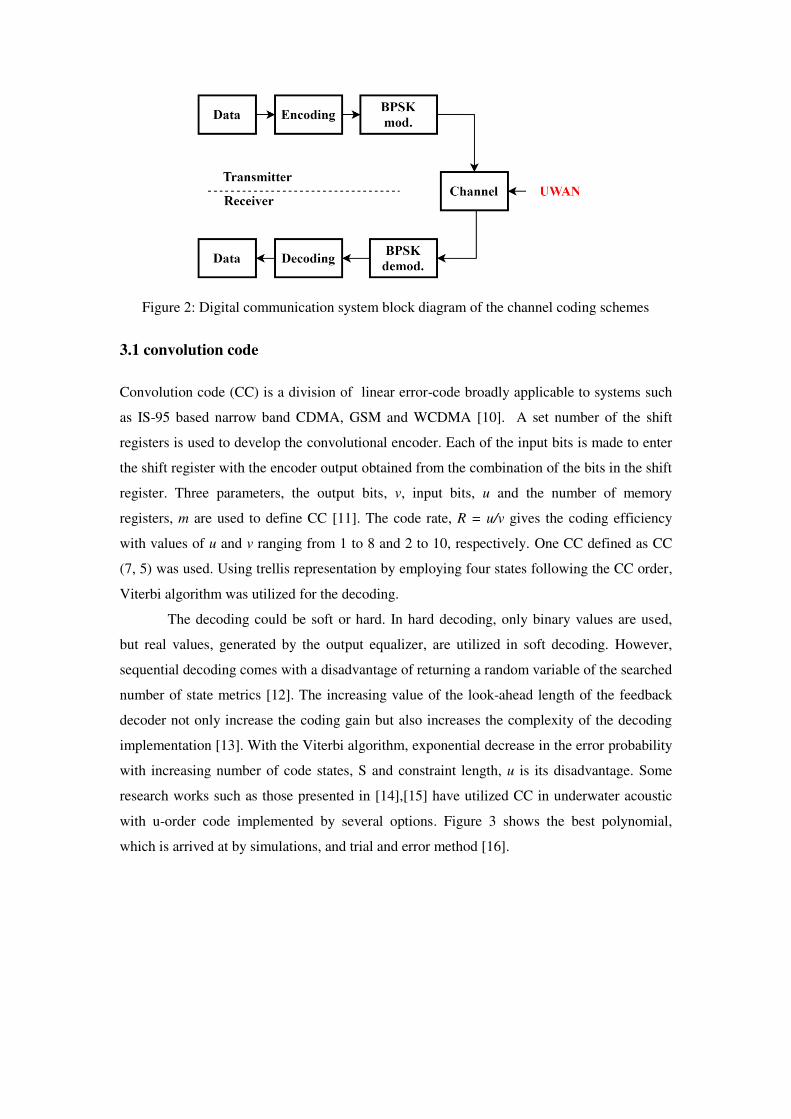
Figure 2: Digital communication system block diagram of the channel coding schemes
3.1 convolution code
Convolution code (CC) is a division of linear error-code broadly applicable to systems such
as IS-95 based narrow band CDMA, GSM and WCDMA [10]. A set number of the shift
registers is used to develop the convolutional encoder. Each of the input bits is made to enter
the shift register with the encoder output obtained from the combination of the bits in the shift
register. Three parameters, the output bits, v, input bits, u and the number of memory
registers, m are used to define CC [11]. The code rate, R = u/v gives the coding efficiency
with values of u and v ranging from 1 to 8 and 2 to 10, respectively. One CC defined as CC
(7, 5) was used. Using trellis representation by employing four states following the CC order,
Viterbi algorithm was utilized for the decoding.
The decoding could be soft or hard. In hard decoding, only binary values are used,
but real values, generated by the output equalizer, are utilized in soft decoding. However,
sequential decoding comes with a disadvantage of returning a random variable of the searched
number of state metrics [12]. The increasing value of the look-ahead length of the feedback
decoder not only increase the coding gain but also increases the complexity of the decoding
implementation [13]. With the Viterbi algorithm, exponential decrease in the error probability
with increasing number of code states, S and constraint length, u is its disadvantage. Some
research works such as those presented in [14],[15] have utilized CC in underwater acoustic
with u-order code implemented by several options. Figure 3 shows the best polynomial,
which is arrived at by simulations, and trial and error method [16].

Figure 3: Convolutional encoder structure [14]
3.2 Turbo code
Turbo codes (TC) are normally comprised of two parallel convolution encoders separated by
an interleaver [17]. The main aim is the selection of suitable interleaver by the construction of
the polynomial codes for individual encoders. With the considerations of the individual
encoders as convolutional, the interleaver is the main element to be analysed and discussed in
the encoding process. Figure 4 shows a turbo encoder using an interleaver. A systematic
stream output, tu and a parity stream, 1b are contained in the first encoder (containing the
systematic and the first parity stream) while only parity stream, 2b is present in the second
individual encoder (containing the interleaved systematic stream and the second parity
stream) resulting to the formation of 1/3 TC. In addition, performance losses are avoided by
acknowledging the first and last states of the encoder at the decoder by trellis termination.
Two soft-input soft-output (SISO) decoders represents the turbo decoder at the decoding unit.
It is worthy of note that both turbo decoders and the convolutional decoders are similar in
structure with only a few variations. The decoding iterative scheme is essentially comprised
of an interleaver, a posteriori probability (APP) decoder and deinterleaver [11].

Figure 4: Turbo code structure [11]
Nevertheless, turbo coding is faced with a major challenge of characteristic delay linked with
both the decoding algorithm and the interleaver [10]. The associated high implementational
complexities could make the block lengths and code rates fail to satisfy the requirements of
UWA [18]. Several submissions have been made on turbo codes and its use in UWA
[5],[10],[19].
3.3 LDPC code
A class of linear error-correction code, Low-Density Parity Check (LDPC) matrix
code, was in 1962, introduced by Gallager [20]. It is characterized by a sparsed parity
check matrix H. WiMAX and DVB-S2 adopted LDPC code. LDPC code can be
considered regular or irregular LDPC codes [21]. It is regular when H has equal
number of ones in each column, wc and the equal number of ones in each row, wr [22].
An example of regular binary LDPC codes [21] is the original Gallager codes [20].
Although, it has generally very large size of H matrix, it has very low the density of
the nonzero element [12]. LDPC code of length, n can be written as (n, wc, wr). Thus,
each information bit is characterized by wc parity checks while each parity check bit is
characterized by wr information bits [12]. An algebraic construction can be used to
represent the parity check matrix, H [21], and by Tanner graph [21]. In this case, the
variable or bit nodes (VN or BN) in Tanner graph is equal to wc, and the check nodes
(CN) is equal to wr connected by 1s in the H matrix. The representation of Tanner
graph is shown in Figure 5. An example of H matrix algebra representation is given in
equation (2) [21].

1 1 1 0 1 1 1 0 0 0 0 0
0 0 0 0 1 1 1 1 0 1 0 1
1 0 0 1 0 0 0 1 1 1 0 1
0 1 0 1 0 0 1 1 1 0 1 0
1 1 1 1 0 0 0 0 0 0 1 1
0 0 1 0 1 1 0 0 1 1 1 0
H
(2)
Figure 5. Tanner graph of the example H matrix
LDPC is a simple code which is characterised by linear time encoding and decoding
with high efficiency and low complexity compared with turbo code. LDPC code is a
high-performance coding scheme of RF communication, however, it is not used in the
UWAC. This is because firstly, a long package (about 1000 bits) is needed whereas
the UWA communication commonly adopts a short package since the channel is
characterised by variable propagation delay and low communication rate [10].
Secondly, it requires more iterations which makes it more complex as compared to
other simplified codes [23].
3.4 Polar code
In 2009, polar codes (PC) were invented by Erdal Arikan [24]. This class of linear
error-correction code was introduced based on polarization technique, a new concept.
PC became active research focus as soon as they were invented. This is owned to the
fact that PC demonstrate promising outcome with increasing capacity. They have
shown better performance over other coding techniques and hence, extended to cover
a number of applications and generalizations as presented in [25]. PC offer very low
complexity and explicit construction encoding and decoding. Furthermore, arbitrary
design of the code rate of a PC is possible making it more flexible for applications to
various scenarios, such as security coding on the physical layer [4]. PC can be defined
as (N, K) with N and K denoting the encoded block and the information block lengths,
respectively. N = 2n, and n ≥ 0 where n is a natural integer [27]. The remaining N − K

indices is called the frozen bit indices [27]. Channel polarization transform is used to
construct the PC [26] with the polarization transform being the encoder, which is
given by the kernel of equation (3) [24].
1 0
1 1F
(3)
For larger input size, the transform is found the Kronecker product of this kernel with
itself. This causes the PC to have lengths of powers of 2. For a code of length N, and
2log ( )n N , the encoder is given by equation (4)
nG F
(4)
where n
F
F is the Kronecker product of F with itself for n times. The encoding is
then carried out as in (4), which is shown in Figure 6 for a code of length 4. In this
study, the technique of Successive Cancellation (SC) decoding is applied as the
decoder for the PC due to the regular structure of the PC.
Figure 6. Polar encoder of length 4.
4. Results and Analyses
This section presents the outcomes of UWA system simulation to evaluate the
performance of channel coding schemes based on t-distribution of the noise channel.
Table 1 shows the simulation parameters applied for the communication scheme. The
analysis of UWA system is evaluated in three phases. Firstly, BER reduction of CC,
TC, LDPC and PC is assessed and compared with the signal to noise ratio (SNR).
Secondly, the computational complexity level was analysed and lastly, the decoding
latency of the channel coding schemes is investigated and discussed. The results of
the simulations were retrieved from simulation in MATLAB using the adopted BPSK
with code rate 1/2.
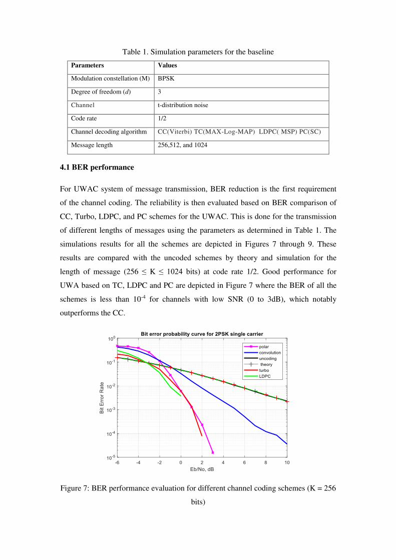
Table 1. Simulation parameters for the baseline
Parameters Values
Modulation constellation (M) BPSK
Degree of freedom (d) 3
Channel t-distribution noise
Code rate 1/2
Channel decoding algorithm CC(Viterbi) TC(MAX-Log-MAP) LDPC( MSP) PC(SC)
Message length 256,512, and 1024
4.1 BER performance
For UWAC system of message transmission, BER reduction is the first requirement
of the channel coding. The reliability is then evaluated based on BER comparison of
CC, Turbo, LDPC, and PC schemes for the UWAC. This is done for the transmission
of different lengths of messages using the parameters as determined in Table 1. The
simulations results for all the schemes are depicted in Figures 7 through 9. These
results are compared with the uncoded schemes by theory and simulation for the
length of message (256 ≤ K ≤ 1024 bits) at code rate 1/2. Good performance for
UWA based on TC, LDPC and PC are depicted in Figure 7 where the BER of all the
schemes is less than 10-4 for channels with low SNR (0 to 3dB), which notably
outperforms the CC.
Figure 7: BER performance evaluation for different channel coding schemes (K = 256
bits)

From Figures 8 and 9, it is clear that polar code scheme is more significant (BER
performance is 10−3 at SNR -1 dB) than TC, LDPC, and CC schemes for different
message lengths (512 ≤ K ≤ 1024 bits) at code rate of 1/2. The PC scheme has better
reliability with an improvement of 1.5 dB channel gain compared with TC scheme at
length [K =512 and 1024 bits] because the SC decoder of polar code has an
acceptable performance in short length messages however, it achieves better results in
longer length messages. Also, Figures 8 and 9 reveal that BER of 10−4 at message K =
512 and 1024 bits is achievable using the TC. Since the message length is short and
TC is characterized by random interleaving, the random position in the medium is not
really very random. Furthermore, the decoding capability is limited by punctured TC
to correct the errors emanating from the removal of some of the parity bits.
Figure 8: BER performance of different channel coding schemes for K = 512 bits

Figure 9: BER performance of different channel coding schemes for K = 1024 bits
4.2 Complexity
The computational complexity is an essential performance metric to be evaluated in
codes building and its applied especially in UWA. Therefore, in this paper, the
complexity evaluation is analysed and discussed, which is important in examining the
computational complexity in the encoding and decoding techniques. In this section, it
is required to understand the complexity of the decoding algorithm used to evaluate
and find the iteration number identical to providing fair comparison for different
schemes. The decoding complexity can be evaluated through multiple mathematical
operations such as addition, subtract, multiplication, division, and comparison. Based
on code building, different result conclusions can be obtained.
The parameters related to the computational complexity of the PC scheme is
calculated and compared with TC, LDPC and CC schemes. Table 2 presents the
equations used in the determination of the number of operations for the various
schemes. The parameters K, R and N denote the information block length, the code
rate and the encoded block length respectively [27] [24]. Additionally, m represents
the memory length of the component for TC and CC [28],[29]; dc and dv represent the
average check degree and average variable degree respectively for LDPC scheme
[30], while Imax stands for the maximum number of iterations.

Table 2. Computational complexity of polar code, turbo code and some of the
previously channel code methods in literature
Method Computational complexity
Polar [24] 2 ( )O Nlog N
Turbo [27] Imax× 16×K×2m+Imax× 8×K×2m
LDPC [30] Imax× 2×N×dv +M× (2×dc-1)+Imax× M×dc
Convolution [28] 4·R·N·2m
Table 3 shows the comparison of the computational complexity of each
studied channel coding scheme with TC scheme. It can be seen that the computational
complexity of PC scheme is kept lowest as compared with other coding schemes
along with the variation of K parameter. This could be attributed that the PC scheme
is constructed based on simple algorithm (Successive Cancellation). Therefore, it is
implemented efficiently by the factor graph of the code that has a structure resembling
the Fast Fourier Transform (FFT) [24]. On the other hand, the coding schemes of TC
and LDPC show higher computational complexity compared with PC and CC
schemes. This is because, they construct base on an iterative algorithm with high
number of iterations leading to increase in the computational complexity. The
comparison is clearly illustrated in Figure 10.
Table 3. comparison of the computational complexity of polar code and turbo code
Code
Scheme
Parameters
Complexity
Complexity Ratio
w.r.t. Turbo
decoder (%) K m dc dv
N=
(K/R) R Imax
Turbo
256
3 - - -
1/2
8 393216 100
LDPC - 7.17 3.58 - 16 142663.68 36.28
CC 6 - - 512
- 65536 16.66
Polar - - - - 4608 1.17
Turbo
512
3 - - -
1/2
8 786432 100
LDPC - 7.17 3.58 - 16 285327.36 36.28
CC 6 - - 1024
- 131072 16.66
Polar - - - - 10240 1.30
Turbo
1024
3 - - -
1/2
8 1572864 100
LDPC - 7.17 3.58 - 16 570654.72 36.28
CC 6 - - 2048
- 262144 16.66
Polar - - - - 22528 1.43

Figure 10. Computational complexity versus information block lengths, K for various
techniques with coding rate of R = 1/2.
4.3 Latency
Latency is considered as the third requirement for the implementation of UWA
communication channel coding schemes. It is defined as the time taken for the
message bits transmitted over all communication blocks as displayed in Figure 2. In
this section, the latency is evaluated and compared in terms of different channel
decoding schemes such as polar, Turbo, LDPC and Convolution coding. The
MATLAB functions tic and toc are used to calculate the decoding latency time with
taking in consideration the type of processor used in the simulation. The simulation
result shown in Figure 11 is the computational latency of the different channel coding
schemes of UWA for transmitted message length of 256 ≤ k ≤ 1024 bits at code rate
of 1/2. The PC gives higher decoding computational latency compared with the other
coding schemes as a result of the serial decoding by SC algorithm. It is time-
consuming and could get worse with an increasing code length, N.

Figure 11. Decoding computational latency
Figure 11 also shows TC (MAX-Log-MAP) and LDPC (MSP) give have a higher
decoding computational latency than CC (Viterbi) owing to the associated iterative
algorithms. Higher decoding computational latency is given by the LDPC (MSP)
compared with the TC (MAX-Log-MAP) since LDPC (MSP) requires more number
of iterations (Imax=16) than the TC (Imax= 8). However, if the system can tolerate large
time delay and complexity, TC will be considered one of the competing error
correction codes.
5. Conclusion
In conclusion, different channel coding schemes of convolution, Turbo, LDPC, and
Polar coding were analysed for UWA system based on the t-distribution noise channel
with BPSK modulation. The evaluated results of the different coding schemes show
that polar coding is the optimum channel coding scheme for UWA as it fulfils user
requirements in terms of BER reduction and low computational complexity.
Moreover, other requirements such as application type, quality, cost, and data
transmission rate are often considered in the choice of channel coding techniques. For
instance, the high-speed data rate requires low computational complexity, whereas an
excellent BER reduction performance is needed for high-quality. Hence, there i9s
always a trade-off between computational complexity and BER reduction

performance in the channel coding techniques. This must be kept firmly considered in
the choice of channel coding technique for BER reduction.
Acknowledgements This research was funded by the Ministry of Higher Education
Malaysia under Fundamental Research Grant Scheme Vot No. K096 and partially
sponsored by Universiti Tun Hussein Onn Malaysia.
References
[1] M. F. Ali, D. N. K. Jayakody, Y. A. Chursin, S. Affes, and S. Dmitry, "Recent
advances and future directions on underwater wireless communications," Archives of
Computational Methods in Engineering, pp. 1-34, 2019.
[2] A. Song, M. Stojanovic, and M. Chitre, "Editorial Underwater Acoustic
Communications: Where We Stand and What Is Next?," IEEE Journal of Oceanic
Engineering, vol. 44, pp. 1-6, 2019.
[3] M. S. Ahmed, N. S. Mohd Shah, Y. Y. Al‐Aboosi, M. S. Gismalla, M. F. Abdullah,
Y. A. Jawhar, et al., "Filter orthogonal frequency‐division multiplexing scheme based
on polar code in underwater acoustic communication with non‐Gaussian distribution
noise," ETRI Journal, vol. 43, pp. 184-196, 2021.
[4] G. Qiao, S. Xing, and F. Zhou, "A Multi-User Detection Scheme Based on Polar
Code Construction in Downlink Underwater Acoustic OFDM Communication
System," IEEE Access, vol. 7, pp. 65973-65981, 15 May 2019 2019.
[5] M. S. Ahmed, N. S. M. Shah, F. Ghawbar, Y. A. Jawhar, and A. A. Almohammedi,
"Filtered-OFDM with channel coding based on T-distribution noise for underwater
acoustic communication," Journal of Ambient Intelligence and Humanized
Computing, pp. 1-14, 2020.
[6] N. S. M. Shah, Y. Y. Al-Aboosi, and M. S. Ahmed, "Error Performance Analysis in
Underwater Acoustic Noise With Non-Gaussian Distribution," TELKOMNIKA, vol.
16, pp. 681-689, 2018.
[7] Y. Y. Al-Aboosi, A. Z. Sha’ameri, and A. H. Sallomi, "Enhancement signal detection
in underwater acoustic noise using level dependent estimation time-frequency de-
noising technique," Journal of Marine Engineering & Technology, vol. 19, pp. 1-14,
2020.
[8] Y. Y. Al-Aboosi, M. S. Ahmed, N. S. M. Shah, and N. H. H. Khamis, "STUDY OF
ABSORPTION LOSS EFFECTS ON ACOUSTIC WAVE PROPAGATION IN
SHALLOW WATER USING DIFFERENT EMPIRICAL MODELS," vol. 12, pp.
6474-6478, NOVEMBER 2017 2017.

[9] J. Huang, S. Zhou, and P. Willett, "Nonbinary LDPC coding for multicarrier
underwater acoustic communication," IEEE Journal on Selected Areas in
Communications, vol. 26, 2008.
[10] L. Liu, Y. Wang, L. Li, X. Zhang, and J. Wang, "Design and implementation of
channel coding for underwater acoustic system," in ASIC, 2009. ASICON'09. IEEE
8th International Conference on, 2009, pp. 497-500.
[11] B. Tahir, S. Schwarz, and M. Rupp, "BER comparison between Convolutional,
Turbo, LDPC, and Polar codes," in Telecommunications (ICT), 2017 24th
International Conference on, 2017, pp. 1-7.
[12] Z. R. M. Hajiyat, A. Sali, M. Mokhtar, and F. Hashim, "Channel Coding Scheme for
5G Mobile Communication System for Short Length Message Transmission,"
Wireless Personal Communications, vol. 106, pp. 377-400, 2019.
[13] B. Sklar, "Digital Communications Fundamentals and Applications," Instructor, vol.
201705, 2017.
[14] J. Trubuil, A. Goalic, and N. Beuzelin, "An overview of channel coding for
underwater acoustic communications," in MILITARY COMMUNICATIONS
CONFERENCE, 2012-MILCOM 2012, 2012, pp. 1-7.
[15] P. Zhu, X. Xu, X. Tu, Y. Chen, and Y. Tao, "Anti-Multipath Orthogonal Chirp
Division Multiplexing for Underwater Acoustic Communication," IEEE Access, vol.
8, pp. 13305-13314, 2020.
[16] S. Bernard, "Digital communications fundamentals and applications," Prentice Hall,
USA, 2001.
[17] C. Berrou, A. Glavieux, and P. Thitimajshima, "Near Shannon limit error-correcting
coding and decoding: Turbo-codes. 1," in Communications, 1993. ICC'93 Geneva.
Technical Program, Conference Record, IEEE International Conference on, 1993,
pp. 1064-1070.
[18] L. Liu, Y. Zhang, P. Zhang, L. Zhou, and J. Niu, "Channel coding for underwater
acoustic single-carrier CDMA communication system," in Seventh International
Conference on Electronics and Information Engineering, 2017, p. 103222S.
[19] M. Falk, G. Bauch, and I. Nissen, "On Channel Codes for Short Underwater
Messages," Information, vol. 11, p. 58, 2020.
[20] R. G. Gallager, "Low-density parity-check codes," IRE Transactions on information
theory, vol. 8, pp. 21-28, 1962.
[21] W. Han, J. Huang, and M. Jiang, "Performance analysis of underwater digital speech
communication system based on LDPC codes," in Industrial Electronics and
Applications, 2009. ICIEA 2009. 4th IEEE Conference on, 2009, pp. 567-570.

[22] M. El-Mahallawy, A. S. TagEldien, and S. S. Elagooz, "Performance enhancement of
underwater acoustic OFDM communication systems," Wireless Personal
Communications, vol. 108, pp. 2047-2057, 2019.
[23] J. Malhotra, "Investigation of channel coding techniques for high data rate mobile
wireless systems," International Journal of Computer Applications, vol. 115, 2015.
[24] E. Arikan, "Channel polarization: A method for constructing capacity-achieving
codes for symmetric binary-input memoryless channels," IEEE Transactions on
information Theory, vol. 55, pp. 3051-3073, 2009.
[25] W. Wang, L. Li, and K. Niu, "An efficient construction of polar codes based on the
general partial order," EURASIP Journal on Wireless Communications and
Networking, vol. 2019, pp. 1-12, 2019.
[26] H. Vangala, E. Viterbo, and Y. Hong, "A comparative study of polar code
constructions for the AWGN channel," arXiv preprint arXiv:1501.02473, 2015.
[27] S. Shao, P. Hailes, T.-Y. Wang, J.-Y. Wu, R. G. Maunder, B. M. Al-Hashimi, et al.,
"Survey of Turbo, LDPC and Polar Decoder ASIC Implementations," IEEE
Communications Surveys & Tutorials, vol. 21, pp. 2309 - 2333, 2019.
[28] M. Sybis, K. Wesolowski, K. Jayasinghe, V. Venkatasubramanian, and V.
Vukadinovic, "Channel coding for ultra-reliable low-latency communication in 5G
systems," in 2016 IEEE 84th vehicular technology conference (VTC-Fall), 2016, pp.
1-5.
[29] C. Berrou, A. Glavieux, and P. Thitimajshima, "Near Shannon limit error-correcting
coding and decoding: Turbo-codes. 1," in Proceedings of ICC'93-IEEE International
Conference on Communications, 1993, pp. 1064-1070.
[30] S.-Y. Chung, G. D. Forney, T. J. Richardson, and R. Urbanke, "On the design of low-
density parity-check codes within 0.0045 dB of the Shannon limit," IEEE
Communications letters, vol. 5, pp. 58-60, 2001.