a comparative study of the mechanical properties and failure...
TRANSCRIPT

Composite Structures 160 (2017) 89–99
Contents lists available at ScienceDirect
Composite Structures
journal homepage: www.elsevier .com/locate /compstruct
A comparative study of the mechanical properties and failure behavior ofcarbon fiber/epoxy and carbon fiber/polyamide 6 unidirectionalcomposites
http://dx.doi.org/10.1016/j.compstruct.2016.10.0370263-8223/� 2016 Elsevier Ltd. All rights reserved.
⇑ Corresponding author.E-mail addresses: [email protected] (Y. Ma), ueda.masahito@
nihon-u.ac.jp (M. Ueda), [email protected] (T. Yokozeki), [email protected] (T. Sugahara), [email protected] (Y. Yang), [email protected] (H. Hamada).
Yan Ma a, Masahito Ueda b, Tomohiro Yokozeki c, Toshi Sugahara d, Yuqiu Yang e,⇑, Hiroyuki Hamada a
aAdvanced Fibro-Science, Kyoto Institute of Technology, Kyoto 606-8585, JapanbDepartment of Mechanical Engineering, College of Science and Technology, Nihon University, Tokyo 101-8308, JapancDepartment of Aeronautics and Astronautics, The University of Tokyo, Tokyo 113-8656, JapandMaruhachi Corporation, Fukui 910-0276, JapaneKey Laboratory of Textile Science & Technology, Ministry of Education, College of Textiles, Donghua University, Shanghai 201620, PR China
a r t i c l e i n f o
Article history:Received 10 September 2016Revised 13 October 2016Accepted 15 October 2016Available online 18 October 2016
Keywords:Polymer matrix compositeFailure behaviorDamage mechanicsPrepreg
a b s t r a c t
Two types of unidirectional carbon fiber reinforced plastic were fabricated using identical carbon fibersbut different matrix systems. Thermoplastic polyamide 6 and thermosetting epoxy were used as matri-ces. A large number of on-axis tensile tests of unidirectional carbon fiber reinforced polyamide 6 (CF/PA6)and the unidirectional carbon fiber reinforced epoxy (CF/Epoxy) laminates were performed. Mechanicalproperties and failure behaviors are discussed based on fiber distribution, impregnation conditions andinterfacial shear strength. Tensile strengths were predicted by means of a modified global load sharingmodel and compared with experimental results. Step-by-step tensile tests revealed the fracture processof 0-degree unidirectional CF/PA6 laminates.
� 2016 Elsevier Ltd. All rights reserved.
1. Introduction
Carbon fiber reinforced plastics (CFRPs) have been used in anextensive range of engineering applications because of their out-standing mechanical properties, which enable lightweight andextended service-life structures [1–5]. Metallic materials havegradually been replaced by CFRP [6–9]. It is well known that themechanical properties of a CFRP are affected by various factorssuch as the properties of the fiber and matrix, the fiber volumefraction, fiber distribution, impregnation of the matrix, and com-patibility between the fiber and the resin (interface and inter-phase). Manufacturing processes such as temperature, pressure,and process time also affect the mechanical properties. Therefore,manymethods to improve the mechanical properties of CFRPs suchas fiber treatment [10–12], post-treatment [7,9], structure opti-mization [7,9,13–15], and micro- or nano-scale filler doping [16–21] have been investigated. One of the most efficient ways to ame-liorate the capability of CFRPs is to choose an appropriate surface
treatment to improve interfacial strength between the fibers andthe matrix.
During loading of a unidirectional (UD) CFRP, mesoscopicevents, such as matrix cracking and fiber breakage, initiate andpropagate progressively. Such damage accumulates with increasedloading. Fiber breakage and matrix cracking often cause interfacialde-bonding [22]. A firm adhesive interface (ideal impregnation ofmatrix and strong bonding between fibers and matrix) is necessaryfor the efficient transfer of stress throughout the interface [23].Modification of the interface could affect fracture modes of a UDCFRP, resulting in disparate mechanical properties [24–28]. Thefracture process of a UD CFRP is not currently well understoodbecause the process is extremely rapid (>500 m/s [29]). Ultimatefailure of a UD CFRP always occurs abruptly after initiation ofmesoscopic events, without any symptoms or visible signs of dam-age serving as an alarm.
Analytical modeling of tensile failure of a UD CFRP, followed byfiber fragmentation is well established. A useful baseline isobtained by assuming that stress re-distribution around brokenfiber follows global load sharing (GLS) [30,31]. This approachassumes that the load from a broken fiber is shared uniformlyand equally to all remaining intact fibers across the cross-sectionof the break point [30–44]. Curtin [30,31] was the first to developan analysis of the stress–strain response of a fragmenting bundle,

90 Y. Ma et al. / Composite Structures 160 (2017) 89–99
based on the Cox’s [32] shear lag model, Rosen’s [33] chain of bun-dle concept and the Kelly–Tyson [34] approximation model forinefficient length. Curtin’s model was later extended by Neumeis-ter [35,36] to account in an approximate way for the overlap ofinfluence zones adjacent to fiber breaks, and subsequently an exactsolution to the fragmentation problem was developed. Furtherresearch using the GLS model has mainly focused on investigatingmechanical behavior, the influencing factors and mechanisms [37–44].
In the present study, a typical thermoplastic resin, polyamide 6(PA6) and a thermosetting epoxy resin were used as matrices tofabricate UD carbon fiber reinforced PA6 laminates (CF/PA6) andepoxy laminates (CF/Epoxy) through hot compression molding.Their failure behaviors and mechanical properties were investi-gated based on the fiber distribution, impregnation conditionsand interfacial shear strength (IFSS). The modified GLS modelwas used to predict tensile strengths, which were then comparedwith experimental results.
2. Experimental methods
2.1. Materials
2.1.1. Production of unidirectional compositesTwo types of UC CFRP were fabricated using one type of carbon
fiber and different matrix systems. Two UD prepreg sheets wereprepared from carbon fibers (T700SC 12K, Toray, Tokyo, Japan)with PA6 (MXD-PA, Mitsubishi Gas Chemical, Tokyo, Japan), andcarbon fibers (T700SC 12K, Toray) with epoxy (MCP939, MaruhachiCorporation, Fukui, Japan). The mechanical properties of the rawmaterials are shown in Table 1. The thickness of a single ply laminawas about 0.1 mm. CFRP laminates with a thickness of 1 mm werefabricated by laminating 10 plies of prepreg sheets with stackingsequences of [0]10 for 0-degree longitudinal tensile tests. Moldingconditions were 280 �C for 3.5 min under a compression pressureof 4 kg/cm2 for CF/PA6 laminates and 130 �C for 50 min under acompression pressure of 25 kg/cm2 for CF/Epoxy laminates. Simi-larly, laminates with thickness of 2 mm and stacking sequencesof [0]20 were prepared for transverse tensile tests. Specimens ofboth CF/PA6 and CF/Epoxy laminates were cut with a size of15 � 250 � 1 and 25 � 15 � 02 (Width � Length � Thickness:
Table 1Mechanical properties of materials.
Material Manufacturer Type
CF Toray T700SC 12 kPA6 Mitsubishi Gas Chemical Company MXD-PAEpoxy Maruhachi Corp. MCP1110
E: Tensile modulus;r: Tensile strength;d:.Elongation;q: Density.* Yield point.$Break point.
Fig. 1. Schematic of specimens used for tensile
mm) for longitudinal and transverse tensile tests, respectively.Rectangular-shaped aluminum-alloy tabs were bonded on bothends of the specimens using an epoxy adhesive (AralditeTM), asshown in Fig. 1.
2.1.2. Sample preparation for microindentation testsFrom the UD composites, specimens of about 2 mm � 25 mm
were cut out and embedded standing upright in a PMMA tubefilled with liquid epoxy resin. In this way, an epoxy resin cylinder,containing a sample of CFRPs at the center with fibers in longitudi-nal direction, is produced. 2 mm thick plate is cut off in order to geta plane perpendicular to the fiber direction.
After cutting, the previously cut face side of the cylinder isgrinded and polished by using SiC abrasive paper with grain sizefrom 400, 600, 800, 1200, 1500–2000 step-by-step, then use thealuminum powder with grain size from 1 mm, 0.1 mm to0.05 mm progressively. For this procedure, the cylinder is clampedin an adapter holding the cylinder perpendicular to the polishingplane. After finishing the first side, the last step in the samplepreparation procedure is to grind and polish the second side ofthe specimen in a similar manner as describe above, till a slice ofcomposite with a thickness of about 100 lm.
2.2. Experimental procedures
2.2.1. Tensile testsAbout 60 pieces of 0-degree specimens and more than 10 pieces
of 90-degree specimens were prepared. The tensile tests were car-ried out on a computer-controlled, screw-driven universal testingmachine (55R4206, Instron, Kanagawa, Japan) equipped with a100-kN load cell at a speed of 1 mm/min on the basis of testingstandard ASTM D3039 [45]. The tensile tests were performed atroom temperature in a relative humidity (RH)-controlled labora-tory (23 ± 0.5 �C, 48 ± 2% RH).
2.2.2. Single-fiber push-out testsSingle-fiber push-out tests were performed using a Berkovich
Indenter with pyramid geometry (Nano Indenter G200, AgilentTechnologies, Oak Ridge, TN, USA), as shown in Fig. 2. The loadwas applied at a constant rate of 0.2 lm/s. For single-fiber push-out tests, the specimen is required to be thin, to allow fracture over
E(GPa) r(MPa) d.(%) q.(g�cm�3)
230 4900 2.1 1.82.4 82*/48
$4.0*/136
$1.1
3.2 80.6 5.4 1.2
tests, based on the ASTM D3039 standard.

Indenter
Matrix
Sample
Foil with holes
F: 100-500 mN
4 mm
1 mm
Fig. 2. Illustration of single-fiber push-out tests layout.
Y. Ma et al. / Composite Structures 160 (2017) 89–99 91
the whole interface of the loaded fiber and to push the latter outcompletely. Prepared thin slice specimens of thickness about100 lm were placed on an aluminum foil with holes. The speci-mens were arranged in such a way that a hole was positioned atthe position of the loaded fibers, enabling the indenter to push-out the fiber completely into the hole.
The IFSS sy is calculated using Eq. (1).
sy ¼ Fmax
2prf lfð1Þ
where Fmax is the load when interfacial debonding occurs, typicallythe initial peak load; rf is the fiber radius (T700S: 3.5 lm); and lf isthe specimen thickness.
2.2.3. Microscope observationThe fiber volume fraction, Vf, was measured on a polished sur-
face of the whole cross-section in a similar way to that describedin Ref. [8]. The fiber volume fraction was measured as follows. (i)Images taken with an optical microscope (VHX-500F CCD camera,KEYENCE, Osaka, Japan, which has a resolution of 1600 � 1200 pix-els) were preprocessed by the aid of ImageJ software. (ii) Functionsin ImageJ software ‘‘Make Binary” and ‘‘Watershed” were used toobtain binary photos, then the function ‘‘Noise? Remove outlier”[46] was used to obtain clear boundary carbon fiber images of CF/PA6 and CF/Epoxy laminates. (iii) The function ‘‘Analyze? Analyze
Particles” was used to calculate the area ratioPFibercrosssection
crosssectionofCFRP
� �,
which is clearly related to the fiber volume fraction because ofits UD characteristics. At the same time, the cross-section of spec-imens was observed to investigate the carbon fiber distributionand crack propagation in CF/PA6 and CF/Epoxy laminates.
2.2.4. Scanning electron microscope observationAll fracture specimens were observed with the optical micro-
scope and then selected samples were coated with an Au-Pd layerand examined in more detail using a scanning electron microscope(SEM, JSM 5200, JEOL, Tokyo, Japan).
3. Modified Global Load Sharing model
The ineffective length d of a fiber embedded in matrix is definedby Eq. (2) according to the Kelly–Tyson approximation [34].
2d ¼ rf rfsy
ð2Þ
where rf is the stress in intact fiber. The probability of fiber break-age Pf(rf, 2d) is a function of rf and 2d, and follows a Weibull distri-bution, as shown in Eq. (3)
Pf ðrf ;2dÞ ¼ 1� exp �2dL0
rf
r0
� �m� �ffi 2d
L0
rf
r0
� �m
ð3Þ
where r0, m, L0 are the Weibull scaling parameter, the Weibullmodulus and the span length to determine the Weibull parameters,respectively. The analytical derivation of the GLS model is intro-duced as follows. The matrix axial stress is neglected; namely thecomposite stress rL can be derived as Vf times the fiber sustainedstress. The fiber sustained stress can be divided into two compo-nents for intact and broken fibers. Thus, the average fiber stress isdefined as the sum of stress in the intact fiber times the probabilityof non-fractured fibers and the recovery stress in the broken fibertimes the probability of failure, as indicated in Eq. (4):
rL ¼ Vf rf f1� Pf ðrf ;2dÞg þ 2syrf
LPf ðrf ;2dÞ� �
¼ rf V f 1� 1� Ld
� �Pf ðrf ;2dÞ
� �ð4Þ
L is a parameter governing the stress recovery rate in brokenfibers. According to the Kelly–Tyson approximation [34], the stressrecovers linearly from the breakage point. Curtin [30,31] hypothe-sized that the average distance from the fiber breakage is half of d,as described in Eq. (5).
L ffi d2
ð5Þ
Taketa [47] improved this hypothesis by taking into account thepossible positions of the fiber fracture in the range of 2d. L in Eq. (5)could then be modified as
L ffi 7d12
ð6Þ
Combining Eqs. (2), (4) and (6), the constitutive expression forcomposite strength can be predicted, as shown in Eq. (7) [47]
rL ¼ rf V f 1� 512
rf
r1
� �mþ1 !
ð7Þ
where
r1 ¼ rm0 L0syrf
� � 1mþ1
ð8Þ
rf ¼ r1
�12
5mþ 10
� 1mþ1
ð9Þ
Then, maximizing with respect to the strain yields, the ultimatetensile strength is
r�L ¼ Vfr1
125mþ 10
� � 1mþ1 mþ 1
mþ 2
� �ð10Þ
To construct a stress–strain curve, the linear relationshipbetween fiber stress and composite strain shown in Eq. (11) canbe substituted into above equations, where Ef is the fiber modulus.
rf ¼ Ef ef ð11Þ
4. Results and discussion
4.1. Fiber distribution
The cross-section of 0-degree CF/PA6 and CF/Epoxy laminatesare shown in Fig. 3(a) and (a’) and in Fig. 3(b) and (b’), respectively.CF/Epoxy laminates exhibited a more uniform fiber distributionthan CF/PA6 laminates. CF/PA6 laminates exhibited a biased/inho-mogeneous fiber distribution; a ‘‘bundle”-like fiber agglomerationwas observed. Poor fiber impregnation areas internally, with fiberconcentrations, were observed in CF/PA6 laminates, as shown inFig. 3(a’). The difference in fiber distribution between the two

Fig. 3. Cross-section of CF/PA6 laminates at low magnification (a) and high magnification (a’) and CF/Epoxy laminates at low magnification (b) and high magnification (b’).Poor impregnation areas and resin concentration areas in CF/PA6 laminates can be observed in (a’).
92 Y. Ma et al. / Composite Structures 160 (2017) 89–99
systems (CF/PA6 and CF/Epoxy) is that epoxy wets the fibers at thepre-polymer stage, while the PA6 resin is already polymerized dur-ing the fiber impregnation process and its ability to infiltrate thefiber bundles is much lower than that of the unreacted epoxy resin.
4.2. Fiber volume fraction
Because of their UD character, the fiber volume fraction of CF/PA6 and CF/Epoxy laminates were calculated according to thecross-sectional ratio between fibers and laminates, which couldbe measured by image analysis software (ImageJ software) asexplained in Section 2.2.3. The results of more than 30 specimensshowed the Vf values for CF/PA6 and CF/Epoxy laminates were42.3% (C:V: �8.8%) and 46.5% (C:V: �7.7%), respectively.
4.3. Interfacial shear strength
The IFSS was approximated by the average shear strength givenby Eq. (1). The IFSS results for CF/PA6 laminates and CF/Epoxy lam-inates are shown in Fig. 4. For CF/PA6 laminates, two kinds of typ-ical areas including a fiber concentration area (CF/PA6-A: poorimpregnation) and a single fiber area (CF/PA6-B: good impregna-tion) were measured, as shown in Fig. 4(a). The results show thatCF/PA6 laminates with good fiber impregnation (IFSS�18.0 MPa)exhibited higher IFSS than CF/Epoxy laminates (IFSS�15.0 MPa).However, the CF/PA6 laminates without good fiber impregnation(IFSS�7.6 MPa) exhibited lower IFSS than CF/Epoxy laminates.The lower IFSS area was dominant and was much larger than thehigher IFSS area in the cross-section of CF/PA6. The IFSS resultsmeasured by the single-fiber push-out tests using the BerkovichIndenter with a pyramid geometry in the present study exhibiteda relatively low IFSS than that measured by other testing methods[47–50]. However, a negative effect of poor impregnation on theIFSS of CF/PA6 laminates could be observed.
4.4. Mechanical properties
4.4.1. Longitudinal loadingMechanical properties of CF/PA6 and CF/Epoxy laminates are
summarized in Table 2. Calculated stress–strain curves of 0-degree laminates from the modified GLS model and typical exper-imental stress–strain curves (CF/PA6: Vf � 0.431, CF/Epoxy:Vf � 0.475) are compared in Fig. 5. The basic parameters includingYoung’s modulus, diameter and gage length, Weibull scale andshape parameters, IFSS and fiber volume fraction used in the pre-sent calculation are shown in Table 3.
The relationship between Vf and tensile modulus and the rela-tionship between Vf and tensile strength, together with resultsfrom the GLS model are shown in Fig. 6(a) and (b), respectively.Vf and tensile modulus exhibited a linear relationship and fittedthe rule-of-mixtures prediction well, as shown in Fig. 6(a). Theexperimental IFSS and that cited from ref [47] were used to predictthe strength by the GLS model. Results indicated that the GLS pre-diction exhibited a good fit to the strength of CF/PA6 laminates.However, the predicted results for CF/Epoxy laminates showed rel-atively high tensile strengths compared with experimental resultsbecause of the relatively low experimental IFSS. The relationshipbetween modulus and strength by tensile tests, together withresults from the GLS model are shown in Fig. 7.
The results shown in Table 2 indicate that there was an appre-ciable scattering of tensile strength. The statistical distribution ofcomposite strengths is usually described by the Weibull equation[51], with the Weibull distribution given by
PF ¼ 1� exp � rf
r0
� �a� �ð12Þ
where PF is the cumulative probability of failure of a composite atapplied tensile strength rf , a is the Weibull modulus (Weibull

Fig. 4. Interfacial shear strength of CF/PA6 and CF/Epoxy laminates measured by push-out tests (a) and Weibull plots of interfacial shear strength for CF/PA6-B and CF/Epoxylaminates (b).
Table 2Mechanical properties of unidirectional laminates.
Composites Alignment Number Vf (%) Tensile modulus (GPa) Tensile strength (MPa)
Mean C.V. (%) Mean C.V.(%) Mean C.V. (%)
CF/PA6 0� 59 42.3 8.8 98.2 8.2 1308.9 9.2CF/Epoxy 67 46.5 7.7 109.1 7.3 1664.0 8.3
CF/PA6 90� 20 – – 7.4 7.3 33.0 15.7CF/Epoxy 11 – – 7.6 6.2 71.8 7.3
C.V.=Coefficient of variation.
Fig. 5. Typical tensile stress–strain curve comparisons between experiments andpredictions from the GLS model.
Table 3Material constants used in calculations.
Material constants CF/PA6 CF/Epoxy
Young’s modulus of fiber (Ef) 230 GPa# 230 GPa#
Diameter of fiber (rf) 7 lm# 7 lm#
Fiber gage length (L0) 100 mm* 100 mm*
Weibull scale factor (r0) 2700 MPa* 2700 MPa*
Weibull shape factor (m) 9.03* 9.03*
Interfacial shear strength (sy) 18 MPa 15 MPaFiber volume fraction (Vf) 42.27% 46.50%
# From Tory Corp;* Cited from Ref [47].
Y. Ma et al. / Composite Structures 160 (2017) 89–99 93
shape parameter), and r0 is a Weibull scale parameter (characteris-tic stress). Taking the logarithm of both sides of Eq. (12), rearrange-ment of the two-parameter Weibull statistical distributionexpression gives the following:
ln lnð 11� Fi
Þ� �
¼ a lnðrf Þ � alnðr0Þ ð13Þ
Hence the Weibull modulus a can be obtained by linear regres-sion from a Weibull plot of Eq. (13). The probability of failure Fi atthe ith ranked specimen from a total of N specimens is obtainedfrom the symmetric rank method as
Fi ¼ i� 0:5N
ð14Þ
where i is rank of the specimen from lowest to highest strength.The Weibull plots of tensile strength for 0-degree UD CF/PA6
and CF/Epoxy laminates are shown in Fig. 8(a). The Weibull modu-lus a for 0-degree CF/PA6 and CF/Epoxy laminates were calculatedto be 13.3 and 14.9, respectively. The difference in Weibull modu-lus can be attributed to the distribution of the flaws that exist inthe composites. It is well known that many defects are formed ina carbon fiber during precursor manufacturing and various subse-quent treatments. The existence of these defects, including fibermisalignment, void and non-impregnation in UD compositesresults in scattering of the tensile strength. As a result, the Weibullmodulus can be regarded as a defect frequency distribution factor[51]. High values of a indicates that there are few defects and theyare evenly distributed throughout the material. Low values of aindicates more defects that are less evenly distributed, causing agreater scatter in strength [52].

Fig. 6. (a) Relationship between Vf and modulus for both CF/PA6 and CF/Epoxy laminates. The continuous line represents the predicted Vf and modulus relation using therule-of-mixtures. (b) Vf and tensile strength for both CF/PA6 and CF/Epoxy laminates. The continuous lines represent the predicted Vf and modulus relation using the modifiedGLS model. The shaded area indicates the scattering of predicted tensile strength using the GLS model, based on the experimental interfacial shear strength results.
Fig. 7. Relationship between tensile modulus and tensile strength of CF/PA6 andCF/Epoxy laminates with different fiber volume fractions.
Fig. 8. Weibull plots of tensile strength for 0-degree (a) and 90-degree (b) unidirectionafracture modes for 0-degree CF/PA6 and CF/Epoxy laminates after tensile tests are mark
94 Y. Ma et al. / Composite Structures 160 (2017) 89–99
4.4.2. Transverse loadingMechanical properties of 90-degree UD CF/PA6 and CF/Epoxy
laminates are shown in Table 2. Results indicate that the transversetensile strengths of CF/Epoxy laminates were more than doublethose of CF/PA6 laminates. The Weibull plots of tensile strengthfor 90-degree UD CF/PA6 and CF/Epoxy laminates are shown inFig. 8(b). The Weibull modulus a for 90-degree CF/PA6 and CF/Epoxy laminates were 7.5 and 16.0, respectively. According tothe IFSS and the transverse strength of UD CF/PA6 and CF/Epoxylaminates, it could be inferred that the poor impregnation of CF/PA6 laminates had negative effects on the mechanical propertiesand their stabilities.
4.5. Fracture behavior
After tensile tests, two typical fracture modes, including split-ting and the step-like mode, of both CF/PA6 and CF/Epoxy lami-nates were observed, as shown in Fig. 9. Specimens fractured inthe step-like mode showed a smoother fracture surface (as shownin Fig. 9(a) and (b)), while specimens fractured in splitting mode
l CF/PA6 and CF/Epoxy laminates. Fracture modes, including splitting and step-likeed in (a).

Fig. 9. Two typical fracture modes of CF/PA6 and CF/Epoxy laminates. (a) Step-likefracture mode of CF/PA6 laminates; (b) Step-like fracture mode of CF/Epoxylaminates; (c) Splitting fracture mode of CF/PA6 laminates.
Y. Ma et al. / Composite Structures 160 (2017) 89–99 95
exhibited a broom-like head (as shown in Fig. 9(c)). The main dif-ference was that 0-degree CF/Epoxy laminates all showed thestep-like fracture mode after tensile tests, while CF/PA6 laminatesexhibited not only step-like fracture modes (�54.7%) but also thesplitting fracture mode (�45.3%). The fracture behavior distribu-tion of CF/PA6 laminates are shown in Figs. 6(b), 7 and 8(a). Thereis no evident relationship between the fracture mode and mechan-ical properties.
4.6. Step-by-step optical observation
To investigate the fracture process in both CF/PA6 and CF/Epoxylaminates, step-by-step tensile tests were carried out. In detail,
Fig. 10. Crack propagation in CF/PA6 laminates under different axis tensile strain via cinitiated from the fiber concentration bundles, in which insufficient bonding existed; (bbreakage; (c) and (c’) strain�1.2%: Crack propagated along the concentration areasobservation.
tensile tests were stopped at strains of 0.2%, 0.8% and 1.2% forCF/PA6 laminates and 0.2%, 0.8% and 1.3% for CF/Epoxy laminates,as shown in Fig. 5. The corresponding polished cross-sections andside-sections of CF/PA6 and CF/Epoxy laminates are shown inFigs. 10 and 11, respectively.
For CF/PA6 laminate, the crack initiated from the fiber concen-tration areas first (strain�0.2%), as shown in Fig. 10(a). With anincrease in tensile strain (strain � 0.8%), the crack propagated intothe fiber concentration areas with little fiber breakage and thenalong the fiber concentration areas with greater fiber breakage(strain � 1.2%), as shown in Fig. 10(b) and (b’) and Fig. 10(c) and(c’), respectively. However, there was no obvious stiffness degrada-tion in the stress–strain relation of CF/PA6 laminates, even thoughthe cracks gradually occurred during the tensile process, as shownin Fig. 5, because of small amount of the damages. In contrast, forCF/Epoxy laminates, there was no obvious crack or fiber breakageup to a tensile strain of 1.3%, as shown in Fig. 11.
The fracture surfaces of CF/PA6 and CF/Epoxy laminates areshown in Fig. 12(a) and (b), respectively. It is clear that morecracks propagated along the fiber concentration areas in CF/PA6laminates and fractured into small parts. In contrast, most ofthe cracks in CF/Epoxy laminates propagated along the thicknessdirection.
Fig. 10 indicates the existence of stress concentration of CF/PA6laminates. Therefore, modified GLS model may not be adequate inthis case, and local load sharing (LLS) model is appropriate alterna-tive. However, the experimental results showed relatively largescatter, which could cause by non-uniform fiber distribution andvariation in interfacial strength from place to place. Non-uniformfiber distribution and interfacial strength variation need to be con-sidered to predict scatter in tensile strengths.
4.7. SEM observation
The SEM observation of fracture surfaces along the fiber direc-
tion (marked ‘‘A�” and ‘‘�AD”, as shown in Fig. 9(a) and (b),respectively) of both CF/PA6 and CF/Epoxy laminates in step-likefracture mode are shown in Fig. 13(a) and (b), respectively. It isclear for CF/PA6 laminates that delamination occurred and cracks
ross-section and side-section observation. (a) and (a’) strain�0.2%: The first crack) and (b’) strain�0.8%: Crack propagated in the concentration areas with little fiberwith greater fiber breakage. (a–c) cross-section observation; (a’–c’) side-section

Fig. 11. Cross-sectional observation of CF/Epoxy laminates under different axis tensile strains via cross-section and side-section observation. (a–a’) strain � 0.2%, (b–b’)strain � 0.8%, (c–c’) strain � 1.3%. (a–c) cross-section observation, (a’–c’) side-section observation.
Fig. 12. Cross-section observation of (a) CF/PA laminates and (b) CF/Epoxy laminates after breakage. More cracks propagated along the fiber concentration areas in CF/PA6laminates and then fractured into small parts. Most of the cracks in CF/Epoxy laminates propagated along the thickness direction.
96 Y. Ma et al. / Composite Structures 160 (2017) 89–99
propagated along the fiber concentration areas, as shown in Fig. 13(a). However, no delamination occurred and few large-scale cracksand smooth fracture surfaces could be observed in CF/Epoxy lam-inates, as shown in Fig. 13(b). The SEM observation of the fracturesurface vertical to the fiber direction (marked ‘‘�B” and ‘‘�BD”, asshown in Fig. 9(a) and (b), respectively) in both CF/PA6 and CF/Epoxy laminates in step-like fracture mode are shown in Fig. 14(a) and (b), respectively. It was found that much of the PA6 resinsurrounding carbon fibers were torn from fibers, which indicatesthat cracks propagated mainly in the lower IFSS area. In contrast,for CF/Epoxy laminates, many cracks propagated in the epoxy
matrices. These representative characteristics indicate that frac-ture of CF/PA6 and CF/Epoxy laminates were dominated by interfa-cial failure and cohesive failure, respectively.
The SEM observation of the fracture surface along (marked‘‘�C” as shown in Fig. 9(c)) and vertical to (marked ‘‘�D” as shownin Fig. 9(c)) the fiber direction of CF/PA6 laminates in splitting frac-ture mode are shown in Fig. 15(a) and (b), respectively. Similar tothe behavior shown in Fig. 13(a), cracks in CF/PA6 laminates prop-agated along the fiber concentration areas, as shown in Fig. 15(a).Representative interfacial failure (adhesive failure) could beobserved in Fig. 15(b).

Fig. 14. SEM observation of the fracture surface of (a) CF/PA6 laminates and (b) CF/Epoxy laminates vertical to the fiber direction. (a’) Large amounts of PA6 resinssurrounding the carbon fibers were torn from the fibers, which could be directly observed in CF/PA6 laminates. In contrast, for CF/Epoxy laminates (b’), many crackspropagated within the epoxy matrices.
Fig. 13. SEM observation of the fracture surface of (a) CF/PA6 laminates and (b) CF/Epoxy laminates along the fiber direction. Cracks propagated along the fiber concentrationareas and delamination occurred in CF/PA6 laminates. No delamination, but axial cracks, occurred in CF/Epoxy laminates.
Fig. 15. SEM observation of the fracture surface along and vertical to the fiber direction of CF/PA6 in splitting fracture mode.
Y. Ma et al. / Composite Structures 160 (2017) 89–99 97
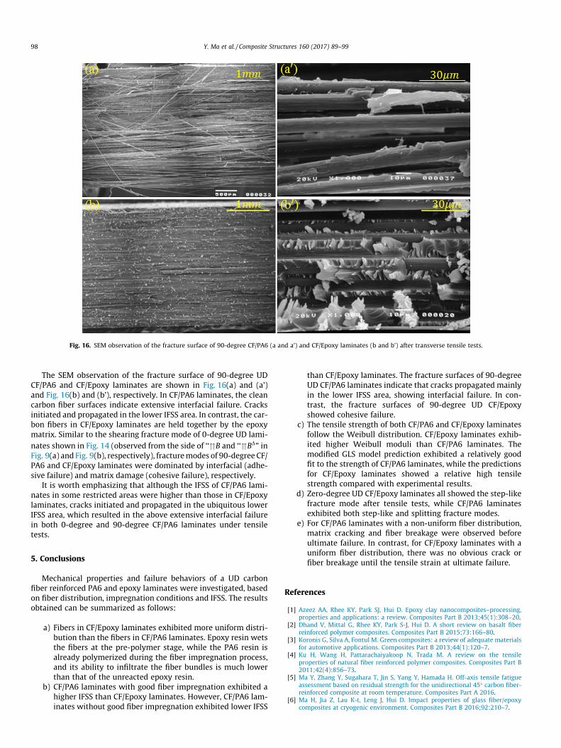
Fig. 16. SEM observation of the fracture surface of 90-degree CF/PA6 (a and a’) and CF/Epoxy laminates (b and b’) after transverse tensile tests.
98 Y. Ma et al. / Composite Structures 160 (2017) 89–99
The SEM observation of the fracture surface of 90-degree UDCF/PA6 and CF/Epoxy laminates are shown in Fig. 16(a) and (a’)and Fig. 16(b) and (b’), respectively. In CF/PA6 laminates, the cleancarbon fiber surfaces indicate extensive interfacial failure. Cracksinitiated and propagated in the lower IFSS area. In contrast, the car-bon fibers in CF/Epoxy laminates are held together by the epoxymatrix. Similar to the shearing fracture mode of 0-degree UD lami-nates shown in Fig. 14 (observed from the side of ‘‘�B and ‘‘�BD” inFig. 9(a) and Fig. 9(b), respectively), fracturemodes of 90-degree CF/PA6 and CF/Epoxy laminates were dominated by interfacial (adhe-sive failure) and matrix damage (cohesive failure), respectively.
It is worth emphasizing that although the IFSS of CF/PA6 lami-nates in some restricted areas were higher than those in CF/Epoxylaminates, cracks initiated and propagated in the ubiquitous lowerIFSS area, which resulted in the above extensive interfacial failurein both 0-degree and 90-degree CF/PA6 laminates under tensiletests.
5. Conclusions
Mechanical properties and failure behaviors of a UD carbonfiber reinforced PA6 and epoxy laminates were investigated, basedon fiber distribution, impregnation conditions and IFSS. The resultsobtained can be summarized as follows:
a) Fibers in CF/Epoxy laminates exhibited more uniform distri-bution than the fibers in CF/PA6 laminates. Epoxy resin wetsthe fibers at the pre-polymer stage, while the PA6 resin isalready polymerized during the fiber impregnation process,and its ability to infiltrate the fiber bundles is much lowerthan that of the unreacted epoxy resin.
b) CF/PA6 laminates with good fiber impregnation exhibited ahigher IFSS than CF/Epoxy laminates. However, CF/PA6 lam-inates without good fiber impregnation exhibited lower IFSS
than CF/Epoxy laminates. The fracture surfaces of 90-degreeUD CF/PA6 laminates indicate that cracks propagated mainlyin the lower IFSS area, showing interfacial failure. In con-trast, the fracture surfaces of 90-degree UD CF/Epoxyshowed cohesive failure.
c) The tensile strength of both CF/PA6 and CF/Epoxy laminatesfollow the Weibull distribution. CF/Epoxy laminates exhib-ited higher Weibull moduli than CF/PA6 laminates. Themodified GLS model prediction exhibited a relatively goodfit to the strength of CF/PA6 laminates, while the predictionsfor CF/Epoxy laminates showed a relative high tensilestrength compared with experimental results.
d) Zero-degree UD CF/Epoxy laminates all showed the step-likefracture mode after tensile tests, while CF/PA6 laminatesexhibited both step-like and splitting fracture modes.
e) For CF/PA6 laminates with a non-uniform fiber distribution,matrix cracking and fiber breakage were observed beforeultimate failure. In contrast, for CF/Epoxy laminates with auniform fiber distribution, there was no obvious crack orfiber breakage until the tensile strain at ultimate failure.
References
[1] Azeez AA, Rhee KY, Park SJ, Hui D. Epoxy clay nanocomposites–processing,properties and applications: a review. Composites Part B 2013;45(1):308–20.
[2] Dhand V, Mittal G, Rhee KY, Park S-J, Hui D. A short review on basalt fiberreinforced polymer composites. Composites Part B 2015;73:166–80.
[3] Koronis G, Silva A, Fontul M. Green composites: a review of adequate materialsfor automotive applications. Composites Part B 2013;44(1):120–7.
[4] Ku H, Wang H, Pattarachaiyakoop N, Trada M. A review on the tensileproperties of natural fiber reinforced polymer composites. Composites Part B2011;42(4):856–73.
[5] Ma Y, Zhang Y, Sugahara T, Jin S, Yang Y, Hamada H. Off-axis tensile fatigueassessment based on residual strength for the unidirectional 45� carbon fiber-reinforced composite at room temperature. Composites Part A 2016.
[6] Ma H, Jia Z, Lau K-t, Leng J, Hui D. Impact properties of glass fiber/epoxycomposites at cryogenic environment. Composites Part B 2016;92:210–7.
Y. Ma et al. / Composite Structures 160 (2017) 89–99 99
[7] Ma Y, Sugahara T, Yang Y, Hamada H. A study on the energy absorptionproperties of carbon/aramid fiber filament winding composite tube. Compos.Struct. 2015;123:301–11.
[8] Ma Y, Yang Y, Sugahara T, Hamada H. A study on the failure behavior andmechanical properties of unidirectional fiber reinforced thermosetting andthermoplastic composites. Composites Part B 2016;99:162–72.
[9] Xu J, Ma Y, Zhang Q, Sugahara T, Yang Y, Hamada H. Crashworthiness of carbonfiber hybrid composite tubes molded by filament winding. Compos. Struct.2016;139:130–40.
[10] Gassan J, Bledzki AK. The influence of fiber-surface treatment on themechanical properties of jute-polypropylene composites. Composites Part A1997;28(12):1001–5.
[11] Liu W, Mohanty AK, Askeland P, Drzal LT, Misra M. Influence of fiber surfacetreatment on properties of Indian grass fiber reinforced soy protein basedbiocomposites. Polymer 2004;45(22):7589–96.
[12] Rong MZ, Zhang MQ, Liu Y, Yang GC, Zeng HM. The effect of fiber treatment onthe mechanical properties of unidirectional sisal-reinforced epoxy composites.Compos. Sci. Technol. 2001;61(10):1437–47.
[13] Awad ZK, Aravinthan T, Zhuge Y, Gonzalez F. A review of optimizationtechniques used in the design of fibre composite structures for civilengineering applications. Mater. Des. 2012;33:534–44.
[14] Jiang T, Kuila T, Kim NH, Ku B-C, Lee JH. Enhanced mechanical properties ofsilanized silica nanoparticle attached graphene oxide/epoxy composites.Compos. Sci. Technol. 2013;79:115–25.
[15] Marín L, Trias D, Badalló P, Rus G, Mayugo J. Optimization of compositestiffened panels under mechanical and hygrothermal loads using neuralnetworks and genetic algorithms. Compos. Struct. 2012;94(11):3321–6.
[16] Wetzel B, Haupert F, Zhang MQ. Epoxy nanocomposites with highmechanical and tribological performance. Compos. Sci. Technol. 2003;63(14):2055–67.
[17] Kelnar I, Kotek J, Kaprálková L, Munteanu B. Polyamide nanocomposites withimproved toughness. J. Appl. Polym. Sci. 2005;96(2):288–93.
[18] Subramaniyan AK, Sun C. Toughening polymeric composites using nanoclay:crack tip scale effects on fracture toughness. Composites Part A 2007;38(1):34–43.
[19] Xu Y, Van Hoa S. Mechanical properties of carbon fiber reinforced epoxy/claynanocomposites. Compos. Sci. Technol. 2008;68(3):854–61.
[20] Wei T, Fan Z, Luo G, Wei F. A new structure for multi-walled carbon nanotubesreinforced alumina nanocomposite with high strength and toughness. Mater.Lett. 2008;62(4):641–4.
[21] Lau K-T, Chipara M, Ling H-Y, Hui D. On the effective elastic moduli of carbonnanotubes for nanocomposite structures. Composites Part B 2004;35(2):95–101.
[22] Tanaka M, Hojo M, Hobbiebrunken T, Ochiai S, Hirosawa Y, Fujita K, et al.Influence of non-uniform fiber arrangement on tensile fracture behavior ofunidirectional fiber/epoxy model composites. Compos. Interfaces 2005;12(3–4):365–78.
[23] Chamis C. Mechanics of load transfer at the interface. In: Plueddemann EP,editor. Interfaces in Polymer Composites. San Diego: Academic Press; 1974. p.33–77.
[24] Keusch S, Queck H, Gliesche K. Influence of glass fibre/epoxy resin interface onstatic mechanical properties of unidirectional composites and on fatigueperformance of cross ply composites. Composites Part A 1998;29(5):701–5.
[25] Selzer R, Friedrich K. Mechanical properties and failure behaviour of carbonfibre-reinforced polymer composites under the influence of moisture.Composites Part A 1997;28(6):595–604.
[26] Boccardi S, Meola C, Carlomagno G, Sorrentino L, Simeoli G, Russo P. Effects ofinterface strength gradation on impact damage mechanisms inpolypropylene/woven glass fabric composites. Composites Part B2016;90:179–87.
[27] Lu T, Liu S, Jiang M, Xu X, Wang Y, Wang Z, et al. Effects of modifications ofbamboo cellulose fibers on the improved mechanical properties of cellulosereinforced poly (lactic acid) composites. Composites Part B 2014;62:191–7.
[28] Lu T, Jiang M, Jiang Z, Hui D, Wang Z, Zhou Z. Effect of surface modification ofbamboo cellulose fibers on mechanical properties of cellulose/epoxycomposites. Composites Part B 2013;51:28–34.
[29] H. Kusano, Y. Aoki, Y. Hirano, T. Hasegawa, Y. Nagao, Visualization on statictensile test for unidirectional CFRP, in: ICCM-17, Edinburgh.
[30] Curtin W. Exact theory of fibre fragmentation in a single-filament composite. J.Mater. Sci. 1991;26(19):5239–53.
[31] Curtin WA. Theory of mechanical properties of ceramic-matrix composites. J.Am. Ceram. Soc. 1991;74(11):2837–45.
[32] Cox H. The elasticity and strength of paper and other fibrous materials. Brit. J.Appl. Phys. 1952;3(3):72.
[33] Rosen BW. Tensile failure of fibrous composites. AIAA J. 1964;2(11):1985–91.[34] Kelly A, Tyson WR. Tensile properties of fibre-reinforced metals:
copper/tungsten and copper/molybdenum. J. Mech. Phys. Solids 1965;13(6).329in1339-338in2-350.
[35] Neumeister JM. Bundle pullout—a failure mechanism limiting the tensilestrength of continuous fiber reinforced brittle matrix composites—and itsimplications for strength dependence on volume and type of loading. J. Mech.Phys. Solids 1993;41(8):1405–24.
[36] Neumeister JM. A constitutive law for continuous fiber reinforced brittlematrix composites with fiber fragmentation and stress recovery. J. Mech. Phys.Solids 1993;41(8):1383–404.
[37] Beyerlein IJ, Phoenix SL, Sastry AM. Comparison of shear-lag theory andcontinuum fracture mechanics for modeling fiber and matrix stresses in anelastic cracked composite lamina. Int. J. Solids Struct. 1996;33(18):2543–74.
[38] Landis C, McGlockton M, McMeeking R. An improved shear lag model forbroken fibers in composite materials. J. Compos. Mater. 1999;33(7):667–80.
[39] Xia Z, Curtin W. Multiscale modeling of damage and failure in aluminum-matrix composites. Compos. Sci. Technol. 2001;61(15):2247–57.
[40] Xia Z, Curtin W, Okabe T. Green’s function vs. shear-lag models of damage andfailure in fiber composites. Compos. Sci. Technol. 2002;62(10):1279–88.
[41] Okabe T, Ishii K, Nishikawa M, Takeda N. Prediction of tensile strength ofunidirectional CFRP composites. Adv. Compos. Mater. 2010;19(3):229–41.
[42] Okabe T, Nishikawa M, Takeda N, Sekine H. Effect of matrix hardening on thetensile strength of alumina fiber-reinforced aluminum matrix composites.Acta Mater. 2006;54(9):2557–66.
[43] Okabe T, Sekine H, Ishii K, Nishikawa M, Takeda N. Numerical method forfailure simulation of unidirectional fiber-reinforced composites with springelement model. Compos. Sci. Technol. 2005;65(6):921–33.
[44] Beyerlein IJ, Phoenix SL. Statistics of fracture for an elastic notched compositelamina containing Weibull fibers—Part I. Features from Monte-Carlosimulation. Eng. Fract. Mech. 1997;57(2):241–65.
[45] Materials ASoT. Standard Test Method for Tensile Properties of Polymer MatrixComposite Materials. ASTM D3039/D3039M-14.West Conshohocken: AmericanSociety of TestingMaterials; 2014.
[46] RossollA,MoserB,MortensenA.Tensile strengthof axially loadedunidirectionalNextel 610TM reinforced aluminium: a case study in local load sharing betweenrandomly distributed fibres. Composites Part A 2012;43(1):129–37.
[47] Taketa I. Analysis of failure mechanisms and hybrid effects in carbon fibrereinforced thermoplastic composites (Ph.D. thesis), 2011.
[48] Liu W, Zhang S, Li B, Yang F, Jiao W, Hao L, et al. Improvement in interfacialshear strength and fracture toughness for carbon fiber reinforced epoxycomposite by fiber sizing. Polym. Compos. 2014;35(3):482–8.
[49] Zhu M, Li M, Wu Q, Gu Y, Li Y, Zhang Z. Effect of processing temperature on themicro-and macro-interfacial properties of carbon fiber/epoxy composites.Compos. Interfaces 2014;21(5):443–53.
[50] Sharma M, Gao S, Mäder E, Sharma H, Wei LY, Bijwe J. Carbon fiber surfacesand composite interphases. Compos. Sci. Technol. 2014;102:35–50.
[51] Weibull W. A statistical distribution function of wide applicability. J. Appl.Mech. 1951;103:293–7.
[52] Naito K, Tanaka Y, Yang J-M, Kagawa Y. Tensile properties of ultrahigh strengthPAN-based, ultrahigh modulus pitch-based and high ductility pitch-basedcarbon fibers. Carbon 2008;46(2):189–95.