a comparative analysis of different...
TRANSCRIPT

Adnan Ghareeb Tuaamah Al-Hasnawi, Eckehard Specht
137
A COMPARATIVE ANALYSIS OF DIFFERENT SPECIAL INJECTOR BURNER DESIGNS BY USING CFD
Adnan Ghareeb Tuaamah Al-Hasnawi1,2, Eckehard Specht1
1 Institute of Fluid Dynamics and Thermodynamics Otto von Guericke University Universitätsplatz 2 D-39106 Magdeburg, Germany2 Training and Workshop Center University of Technology-Baghdad Tal Muhammad 35010, Baghdad, Iraq E-mail: [email protected]
ABSTRACT
Hot air from the cooling zone of a continuous kiln is available at the end of the corresponding firing zone. It can be used again with the application of special injectors. 3D simulations in a domain containing injector nozzles are carried out to evaluate the temperature distribution inside the continuous kiln in case of using the hot air which comes from the cooling zone. The roller hearth kiln is taken as a computational domain in this study. Parameters referring to the direc-tion of the burner streamline, the quantity of the air sucked and the effect of the cone length are studied. The temperature distribution at the outlet is determined in case of fixing the burner against or along the direction of the main flow. It is shown that the maximum air velocity at the outlet of the burner cone is about 90m/s. The upstream model temperature distribution is found better than the downstream one. It is also suggested that a burner with longer outlet duct can protect the product from direct exposure to the flame.
Keywords: continuous kiln, ceramic products, CFD, flow mixing, pre mixed combustion.
Received 13 September 2016Accepted 25 November 2016
Journal of Chemical Technology and Metallurgy, 52, 1, 2017, 137 - 147
INTRODUCTION
Continuous kilns are extensively used in industry for the production of a wide range of ceramics (bricks, tiles, sanitary ware, porcelain, vitrified clay, etc.). Tunnel kilns and roller hearth kilns are the major variants of the continuous kiln. The materials are placed on cars in the latter or on rollers which are pushed slowly through the kiln. The middle section of the kiln contains of a row of burners. There, the fuel and air injected flow in a counter current to the material through the kiln. The hot gases heat up the material to the sintering temperature. The design of the continuous kiln depends on the product, which in turn affects the cross section. Providing a homogeneous temperature in the cross section presents a definite problem. The flow and heat transfer there must be known to simulate the kiln process. Therefore
a lot of studies referring to the heat transfer and the simulation of the firing process in the continuous kilns are carried out. A. Mezquita et al. present a calculation methodology based on certain kiln operating param-eters aiming to save energy. They suggest recovering a part of cooling gases in the firing chamber instead of their exhaustion into the atmosphere. According to them the static pressure and oxygen content profiles in the studied ceramic tile kiln verify that gases from the fast cooling zone enter the combustion chamber. Furthermore, they find that the air and gas volume flow rates in each burner ring and the oxygen content in the kiln chamber enable the gas volume flow rate from the cooling to the firing zone. Furthermore, the results are compared with experimental data. It is concluded that 17 % of the energy can be saved in the kiln. M. Han et al. [2] propose an optimization process for fuel and air

Journal of Chemical Technology and Metallurgy, 52, 1, 2017
138
used around a tunnel kiln. Real process data is used to calculate the energy to be supplied by fuels using the corresponding mass and energy balances. They find that the use of admixed coal in case of pulverized coal or natural gas in the firing zone is advantageous. The admixed coal improves the heating value of pulverized coal, thereby causing no significant change of the fuel cost. Natural gas eases the combustion providing good control of the temperature profile in the firing zone, and decreasing the environmental degradation. S. Kaya et al.[3] improve the firing zone to minimize the fuel cost by finding the optimal operating variables. Mathemati-cal models are used to present the simplest form of the phenomena of heat transfer, combustion of admixed coal and pulverized coal, together with gas flow. They conclude that the overall energy balance predicts an energy use of 3385 KJ/kg brick, which is 2.7 % higher than the optimized results. S. Kaya et al. [4] optimize the heat recovery in the firing zone by finding the opti-mum suction and air blown. The mathematical model presents the phenomena of heat transfer and fluid flow. It treats also state variables such as the air mass flow rate, the brick and air temperatures along the cooling zone of a tunnel kiln. They find that the minimum pressure drop is obtained when the tunnel kiln’s cooling zone is composed of two regions of suction and two regions of blowing. S. H. Pulko et al. [5] carry out modelling of a tunnel kiln to study the behaviour of ceramics during firing and their variation with time. The TLM technique is used to model the heat conduction within the ceramic. It is accepted that the radiation affects the kiln function and any visible burner, as well as the contact surface between two ceramic bodies, that between a ceramic body and the kiln walls. The results demonstrate the feasibility of a ceramic piece deformation during firing.
Regarding CFD simulations, A.H. Tehzeeb et al. [6] develop a new model for brick production in a tunnel kiln by using ANSYS. One-sixth of the width (540 mm) is taken in the simulation because of kiln symmetric geometry. The turbulence (k-ε) model is chosen for turbulence modeling. They estimate that CO2 and NOx volumes generated inside the kiln refer to 1.010 m3/s and 0.108 m3/s, respectively. The direction of the air and gas flow and velocity inside the tunnel are identified. Fur-thermore, the simulation results are validated through a comparison with values provided in a previous research and real emission data. R. Oba et al. [7] present a nu-
merical model to simulate a tunnel kiln used in ceramic industry. The tile load is presented as a single block. The domain of the resolution is divided in sub-domains of different volumes. The model is solved for the energy distribution in the burning zone, the radiation between the ceramic load and the refractory walls, the advec-tion of gases inside the kiln and the energy loss from the kiln to the surroundings. Vicent et al. [8] elaborate a numerical simulation of a tunnel kiln used for firing clay tiles, bricks, and similar products using natural gas and sawdust as fuels. They develop a thermal model which provides efficient energy consuming design. The results show how the fuel consumption decrease brings about increase of the walls thermal insulation thickness and affects the load internal area of heat exchanged with combustion gases inside the kiln. It is also shown that a greater number of less tortuous channels inside the load are required to promote efficient gas circula-tion. The numerical simulation results are compared to experimental values. R. Oba et al. [9] present a thermal analysis of a tunnel kiln used for the production of roof tiles using firewood and shale oil. A three dimensional numerical model based on the finite volume method is used to describe the thermal behaviour of the kiln. They use the prescribed flue gas and air flow to overcome the obstacle of high computational cost due to the large di-mensions of the numerical domain. The results obtained show that 35 % of the energy input to the kiln is lost through the walls and the roof to the surroundings. Also, the radiation heat flux is found of greater significance to the heat transfers to and from the load accounting for more than 75 % of the heat transfer. T. S. Possamai et al. [10] advance a model of thermal energy transport in ceramic frits melting kilns with oxy-firing combustion process. They develop a numerical simulation in Fortran language coupled with simulation in CFD software. The rectangular refractory kiln working at a mean inside temperature of 1400oC is used as a domain in the analy-sis. The k-ε model is adopted for turbulence modelling. The effect of several variables in the process such as the kiln geometry, the burner position, the fuel and the oxidizing type is studied. CFD results are compared to experimental data and prove that the mathematical models used in the numerical simulation are practically consistent. Furthermore, the comparisons to the global results from the FORTRAN code are expected to show even higher accuracy.
Adnan Ghareeb Tuaamah Al-Hasnawi, Eckehard Specht
139
The literature review provides guidelines and an extensive background for the present study. It is clear that most of the models and simulations are focused on the thermal process aiming kiln efficiency improvement.
A hot air rich in oxygen is available between firing and cooling zone. It can be used again in the firing zone through a special injector. There is no study reporting the use of air from the cooling zone in the firing zone of a continuous kiln. That is why the present work reports on the investigation of the temperature distribution in the firing zone of a continuous kiln and the flame behaviour under different geometric and operation parameters in case of us-ing a special injector nozzle. This work can also contribute to a number of aspects of industrial interest such as cost reduction, productivity and efficiency increase.
General conditionsIn premixed flames, the fuel and oxidizer are inti-
mately mixed before they enter the combustion device. In many industrial premixed systems, combustion takes place in a thin flame sheet. The premixed combustion model considers the reacting flow field to be divided into regions of burnt and unburnt species separated by the flame sheet. The flame front propagation is modelled by solving a transport equation for the density-weighted mean reaction progress variable, denoted by c [11].
𝜕𝜕𝜕𝜕𝜕𝜕
(𝜌𝜌𝑐𝑐) + ∇ ∗ (𝜌𝜌𝑣𝑣 𝑐𝑐) = ∇ ∗ � 𝜇𝜇𝜕𝜕𝑆𝑆𝑐𝑐𝜕𝜕∇𝑐𝑐� + 𝜌𝜌𝑆𝑆𝑐𝑐 (1)
where ρ is the density, v is the mean reaction progress variable, Sc is the reaction progress, tSc is the source term, v is the velocity, is the turbulent Schmidt number, while μt is the turbulent viscosity.
The value of c is defined as a boundary condition at all flow inlets. It is usually specified as either 0 (unburnt) or 1 (burnt) [11].
The ratio between air to fuel (methane) is 9:1, which is the stoichiometric combustion ratio. The non-adiabatic premixed combustion (Zimont) model and the k- model are used to carry out this work. The governing equations (continuity, momentum, energy equations) for flow field, temperature distribution and heat transfer in the studied domain are solved in the Cartesian coordinate system [11, 12].
( ) 0 ii
Ux
ρ∂=
∂ (2)
( ) ( ) jj i
i i i i
U PU Ux x x x
ρ µ∂∂ ∂ ∂
= −∂ ∂ ∂ ∂
(3)
( ) ( ) p ji i i
TC U T kx x x
ρ ∂∂ ∂=
∂ ∂ ∂ (4)
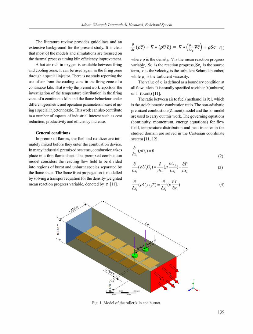
Fig. 1. Model of the roller kiln and burner.

Journal of Chemical Technology and Metallurgy, 52, 1, 2017
140
where, Ui and T are the time-averaged velocity and tem-perature in i direction. с, Cp, k, м and P are the density, specific heat, thermal conductivity, viscosity and static pressure, respectively.
Geometry and process simplification of the con-tinuous kiln
The special injector nozzle is used in different con-tinuous kilns. In this study the roller hearth kiln is taken as a computational domain. ANSYS ICEM CFD is used to draw the geometry. The typical roller kiln is 126m long, 1.45 m wide and 0.872 m high [13]. This kiln is used for producing tiles. The typical tile dimensions are 0.045x0.045x0.007 m. The roller kiln sample has four burners with premixed combustion. These burners are placed on the roof of the roller kiln. As shown in Fig. 1, a half of the kiln total width is taken as a studying domain
to minimize the simulation time.There is a bore hole on the roof. It allows the injector
to suck air from inside of the kiln channel and use it in the combustion process. The burner dimensions refer to a diameter of 0,024 m, length of 0.5 m, an output diameter of 0.034 m with a slope of 28.3 and 0.044 m diameter of the orifice to suck air. The cone dimensions refer to an outlet diameter of 0.006m and length of 0.031 m as shown in Fig. 2. To find the temperature distribution at the outlet in two cases (the burner fires against the main flow or along the main flow), a new geometry is created to decrease the computation time but provide accurate re-sults. The empty cube with orifice at the mid length of the kiln is proposed. The slop of the burner is not considered here. The unborn mixture is injected from the ending edge of the burner, as shown in Fig. 3.
Fig. 2. Model of the burner system.

Adnan Ghareeb Tuaamah Al-Hasnawi, Eckehard Specht
141
Fig. 3. Modelling of the combustion chamber.
Fig. 4. a) Show location of the density region; b) Mesh with the prism layer of the different size element.

Journal of Chemical Technology and Metallurgy, 52, 1, 2017
142
Grid design and mesh independence studyVarious meshes are generated in the combustion
chamber to study the mesh independence. The mesh is generated using the tetra/mixed method (Delaunary) with a prism layer. In general, the Delaunary method is considered more suitable for CFD simulations. This method roots from the surface and proceeds further to the top filling the whole geometry.
Five different meshes are generated by applying the maximum size element. The mesh in the region that is in front the burner is maintained fine by using the density region method. Thus, the density region is not a part of
the geometry, but is used only to refine the mesh in a volumetric zone as shown in Fig. 4a. Fig. 4b presents three different grid settings. The details referring to the different mesh sitting are listed in Table 1.
The global element scale factor is 1, while the maxi-mum size of the burner and the density region are 0.003 and 0.007, respectively.
The influence of the grid number is described as temperature. Fig. 5 shows the peak temperature, which depends upon the grid number. It can be seen that the peak temperature increases with increase of the number of elements.
Fig. 5. Grid independence study for the computational domain.
Fig. 6. 3D modelling of combustion chamber.

Adnan Ghareeb Tuaamah Al-Hasnawi, Eckehard Specht
143
The temperature distribution curve changes to a line and the peak temperature remains constant at 1144.22°C when the grid number increases to 2888541cells. The results referring to the simulated temperature distribu-tion obtained from model No.4 are illustrated in Fig. 6. It illustrates the 3D model mesh chosen for simulation of the combustion chamber.
The computational mesh represents the geometry of the region of interest. Therefore, the burners mesh is extremely fine with a maximum element size of 0.003. It is used to study the direction of the streamline, the quantity of the air sucked and the maximum velocity for
the different burner designs. The maximum element size for the whole geometry and the perimeter of the tiles is 0.1 and 0.04, respectively. The total element is 5413676. Fig. 7 shows the roller kiln mesh.
RESULTS AND DISCUSSION
Three different designs are proposed to study (i) air sucked directly (ii) air sucked by bore hole in the roof insulation (iii) air sucked by bore hole in the roof insulation with a longer burner outlet. The results in this section include the influence of the cone length, the amount of air suction, and the behavior of the streamline (without combustion). This is the scope of this research.
The second purpose is to find the temperature dis-tribution at the outlet (with combustion) in two different cases, when the burner is installed against the direction of the main flow (Upstream), and when the burner is installed in the direction of the main flow (Downstream).
The effect of the three different burner designs on the velocity distribution and on the direction of the
Table 1. Mesh setting details.
Mesh No. Max size Cells number
1 0.1 2641966 2 0.07 2645324 3 0.04 2751402 4 0.03 2888541 5 0.02 3674289
Fig. 7. 3D modelling of the roller kiln and burner.Fig. 8. Contours of velocity distribution at z = 0.978 m in longitudinal direction.

Journal of Chemical Technology and Metallurgy, 52, 1, 2017
144
Fig. 9. (a) burner; (b) velocity distribution inside the burner system at different levels.

Adnan Ghareeb Tuaamah Al-Hasnawi, Eckehard Specht
145
streamline is demonstrated in Figs. 8 and 9.Fig. 8 illustrates the contours of the velocity distribu-
tion inside the roller kiln on the ground of the different models. Fig. 8 (i) shows the first design burner installed with orifice of suction air exposed along the stream of the main flow, so that air is sucked directly from the surrounding. Fig. 8 (ii) and (iii) show the air is sucked by bore hole in the roof insulation.
The outlet of the burner is supplied with a guide at an angle of 28.3o to control the direction of the stream. This is applied to the other models too. The velocity of the main flow is 2 m/s, and air is injected into the burner with velocity of 12 m/s.
Fig. 8 shows that the velocity distribution is similar in all models. Furthermore, the streamline is exposed directly on the tiles in the first and second models, while in the third model (iii) the streamline is not tangential to the product. A steam guide is used in all models.
The velocity distribution at different levels within the burner is shown in Fig. 9. Fig. 9a shows the posi-tion of the selected points along the burner. Fig. 9b (i) shows that the velocity distribution changes completely
and increases in the suction region (between 0.9 m and 0.872 m). The same behavior is observed in the other designs as shown in Fig. 9b (i) and (ii). It is seen that the maximum velocity is about 90 m/s at the cone outlet, and it is decreased to 20 m /s at the burner outlet. The value of air sucked is about 13 m3/h, 15 m3/h and 12 m3/h, respectively. Furthermore, the cone length is studied. It is found that when its length is increased twice, the air sucked increases with about 40 %.
The shape of the premixed flame referring to two cases (the burner fires in the same direction and against the direction the main flow) is presented in Fig. 10. The temperature of the main flow and of the mixture (from the burner) is 1000°C and 600°C, respectively, while the velocity is 2 m/s and 12 m/s, correspondingly.
Fig. 10a illustrates the buoyancy effect of the burner fired in the direction of the main flow (downstream flow). On the other hand, it is worth noting that the temperature around the burner as shown in figure 10b (upstream flow) has better distribution.
Fig. 11 shows the temperature distribution at the outlet of the kiln in two different cases, upstream and
Fig. 10. Influence of the burner direction on temperature contours (a) downstream flow; (b) upstream flow.

Journal of Chemical Technology and Metallurgy, 52, 1, 2017
146
downstream of the main flow. The width of the tempera-ture distribution is not very different, always between 1000°C and 1163°C, but there is a very small increase in upstream case. Moreover, it can be observed that the peak of temperature distribution in the downstream case increases about 14 % when compared to the upstream one. This is due to the impact of the main flow on the temperature distribution in the domain.
CONCLUSIONS
3D simulations are carried out to a part of a continu-ous kiln by using ANSYS-14 aiming to study a special injector nozzle introduction. The standard k-e turbulence model is used in this study. The mixing and the stream-line in the kiln are visualized by temperature contours in the cross section of the kiln. The post-process is used to show the effect of the parameters considered on the mixing and the streamline of the burner. Based on CFD results the following conclusions are drawn:
l The maximum velocity at the outlet of the cone in case of a roller kiln is about 90 m/s.
l The upstream model provides better temperature distribution in the cross-section area than the down-stream one in case of a roller hearth kiln.
Burner with longer outlet protects the product from
direct exposure to the flame in case of a roller hearth kiln.
REFERENCES
1. A. Mezquita, J. Boix, E. Monfort, G. Mallol, Energy Saving in Ceramic Tile Kilns: Cooling gas heat re-covery, Appl. Therm. Eng., 65, 1-2, 2014, 102-110.
2. E. Mancuhan, K. Kucukada, Optimization of Fuel and Air Use in a Tunnel Kiln to Produce Coal Admixed Bricks, Appl. Therm. Eng., 26, 14-15, 2006, 1556-1563.
3. S. Kaya, E. Mançuhan, K. Küçükada, Modelling and Optimization of the Firing Zone of a Tunnel Kiln to Predict the Optimal Feed Locations and Mass Fluxes of the Fuel and Secondary Air, Appl. Energy, 86, 3, 2009, 325-332.
4. S. Kaya, K. Küçükada, E. Mançuhan, Model-Based Optimization of Heat Recovery in The Cooling Zone of a Tunnel Kiln, Appl. Therm. Eng., 28, 5-6, 2008, 633-641.
5. S.H. Pulko, A.L. Hurst, H.R. Newten, Simulation The Behaviour of Ceramics During Firing, Department of Electronics Engineering University of Hull Cottingham.
6. A.H. Tehzeeb, M. Bhuiyan, N. Jayasuriya, Evaluation of Brick Kiln Performances Using Computational
Fig. 11. Temperature distribution at outlet of the kiln as a function of burner.

Adnan Ghareeb Tuaamah Al-Hasnawi, Eckehard Specht
147
Fluid Dynamics, Energy Environ. Eng. 1, 2, 2012, 1-8.7. R. Oba, T. S. Possamai, V.D.P. Nicolau, Numerical
Simulation of Tunnel Kilns Applied To White Tile With Natural Gas, 21st Brazilian Congrress Of Mechanical Engineering, Natal, RN, Brazil, 2011, 24-28.
8. V.D.P. Nicolau, A.P. Dadam, Numerical and Experimental Thermal Analysis of a Tunnel Kiln Used in Ceramic Production, J. Brazilian Soc. Mech. Sci. Eng., 31, 4, 2009, 297-304.
9. R. Oba, T.S. Possamai, V.P. Nicolau, Thermal Analysis of a Tunnel Kiln Used to Produce Roof Tiles,
Appl. Therm. Eng., 63, 1, 2014, 59-65.10. T.S. Possamai, R. Oba, V.D.P. Nicolau, Numerical
Simulation of a Ceramic Kiln Used in Frits, 20th International Congress of Mechanical Eng. Gramdo, RS, Brazil, 2009, 15-20.
11. ANSYS Inc., ANSYS FlUENT 14.0 Theory Guide, Canonsburg, USA, 2009.
12. H. Struchtrup, Thermodynamics and Energy Conversion, Springer-Verlag, Berlin Heidelberg, 2014.
13. F. Becker, Becker Energy Consulting, Elsterweg 6 90530 Wendelstein, Germany.