a command and control vehicle of a … · title of thesis: a command and control vehicle for the...
TRANSCRIPT
AD-A258 888
A COMMAND AND CONTROL VEHICLEFOR THE LIGHT CAVALRY REGIMENT
OF A CONTINGENCY CORPS
A thesis presented to the Faculty of the U.S. ArmyCommand and General Staff College in partial
fulfillment of the requirements for thedegree
MASTER OF MILITARY ART AND SCIENCE
DTICELECTE
S DEC3 01992D[1by
MARK W. MAIERS, MAJ, USAB.S., UNIVERSITY OF NEW YORK AT ALBANY, NEW YORK, 1986
Fort Leavenworth, Kansas1992
Distribution for public release; distribution is unlimited.
0639232796
11me n enN N n n gu n nnum n ninuul IIIONI enn n
REPORT DOCUMEN'(ATION PAGE ) Fo, .Ap07o401
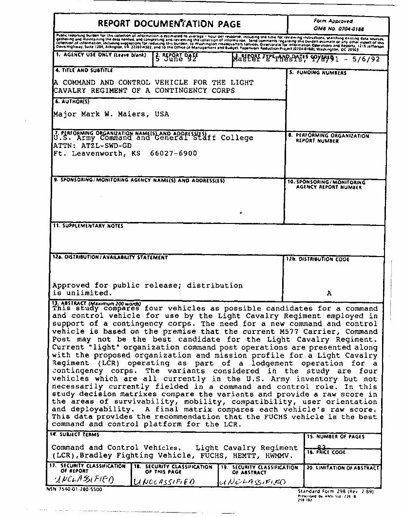
P~~~~~~~~~~~(~~~4- Teotn ~ee o hi o~toto n~miont~m~dt ~r~ I ~ GEC 100E114. 1ACIdi~nq the time foe rev.e.,nq ~ ~ ft Weh n o . data st0..eLndd .ea~ information. sand comments ato d-At AsP of thisC0414%11901 of information. ifidwiclng swgaevhionl foe reducitiq this W~ed~n. to Wasihngton -4,1adquaoFlerl Sef..chs i. rec~orat. roe information OP~atiOns and he"oni. 1213 ieff omonOavrs Highway. lUite 1204. Arlington. VA22202-40)0. and to the office of Managem~ent and 6Iwd~et. 'apeWOek fedct~on Piolec (0704-01111). Washingtonu. OC 2010).1. AGENCY USE ONLY (Leave blank) . I R ORT O4 •EP u n e 04YA RpiIoY r"SW "Ie~ CIPy 8Rý9l1 - 5/6/9 2
4. TITLE AND SUBTITLE S. FUNDING NUMBERS
SCOMMAND AND CONTROL VEHICLE FOR THE LIGHTCAVALRY REGIMENT OF A CONTINGENCY CORPS
6. AUTHOR(S)
Major Mark W. Maiers, USA
7. PERFORMING OIUANIZATIOr NAMIa(ShAN OfAOO 1f. College 8. PERFORMING ORGANIZATIONU PFArmy CommanT a Senera(ff College REPORT NUMBERATTN: ATZL-SWD-GDFt. Leavenworth, KS 66027-6900
9. SPONSORING/MONITORING AGENCY NAME(S) AND ADORESS(ES) 10. SPONSORING/ MONITORINGAGENCY REPORT NUMBER
11. SUPPLEMENTARY NOTES
12a. OISTRIBUTION / AVAILABIUTY STATEMENT 12b. DISTRIBUTION CODE
Approved for public release; distributionis unlimited. A
13. ABSTRACT (Maximum 200 words)This study compares four vehicles as possible candidates for a commandand control vehicle for use by the Light Cavalry Regiment employed insupport of a contingency corps. The need for a new command and controlvehicle is based on the premise that the current M577 Carrier, CommandPost may not be the best candidate for the Light Cavalry Regiment.Current "light" organization command post operations are presented alongwith the proposed organization and mission profile for a Light CavalryRegiment (LCR) operating as part of a lodgement operation for acontingency corps. The variants considered in the study are fourvehicles which are all currently in the U.S. Army inventory but notnecessarily currently fielded in a command and control role. In thisstudy decision matrixes compare the variants and provide a raw score inthe areas of survivability, mobility, compatibility, user orientationand deployability. A final matrix compares each vehicle's raw score.This data provides the recommendation that the FUCHS vehicle is the bestcommand and control platform for the LCR.14. SUBJECT TERMS iS. NUMBER OF PAGES
Command and Control Vehicles, Light Cavalry Regiment 16. HE CODE(LCR),Bradley Fighting Vehicle, FUCHS, HEMTT, HWMMV.
17. SECURITY CLASSIFICATION 18. SECURITY CLASSIFICATION 19. SECURITY CLASSIFICATION 20. LIMITATION OF ABSTRACTOF REPORT OF THIS PAGE OF ABSTRACT
"4/L'"/-1 91FI I U /JcL/- 4/59 F, F0 lc-i A/)C-4 t ,-,l+Z)NSN 7540-01-280-5500 Standard Form 298 (Rev 2 89)
P'e,14ied bir AN15 Sid 119 I146 '02

A COMMAND AND CONTROL VEHICLEFOR THE LIGHT CAVALRY REGIMENT
OF A CONTINGENCY CORPS
A thesis presented to the Faculty of the U.S. ArmyCommand and General Staff College in partial
fulfillment of the requirements for thedegree
MASTER OF MILITARY ART AND SCIENCE
by
MARK W. MAIERS, MAJ, USAB.S., UNIVERSITY OF NEW YORK AT ALBANY, NEW YORK, 1986
Accesion For
NTIS CRA&IDTIC TAr3 77
Uianou..CeJ fJdstification ......................
B y ..................................................
Distribution IFort Leavenworth, Kansas
1992 AvailabJ',ijt,Cc,--
Av•,I I .:Dist
D ftSIst
Distribution for public release; distribution is unlimited.
MASTER OF MILITARY ART AND SCIENCE
THESIS APPROVAL PAGE
Name of candidate: Major Mark W. Maiers
Title of thesis: A Command and Control Vehicle for the LightCavalry Regiment of a Contingency Corps
Approved by:
&•/•1E Thesis Committee Chairman
oln -Rbrt Hurle S.
U " te-kc•"J Member
Lieutenant Colonel Jon Moilanen, M.A.
Accepted this 5th day of June 1992 by:
____" 4____/____ ____ , Director, Graduate DegreePlilip t. Brookes, Ph.D. Programs
The opinions and conclusions expressed herein are those of thestudent author and do not necessarily represent the views ofthe U.S. Army Command and General Staff College or any othergovernmental agency.
ii
ABSTRACT
A COMMAND AND CONTROL VEHICLE FOR THE LIGHT CAVALRY REGIMENTOF A CONTINGENCY CORPS by Major Mark W. Maiers, USA, 78 pages.
This study compares four vehicles as possible candidates fora command and control vehicle for use by the Light CavalryRegiment employed in support of a contingency corps. The needfor a new command and control vehicle is based on the premisethat the current M577 Carrier, Command Post may not be thebest candidate for the Light Cavalry Regiment.
Current "light" organization command post operations arepresented along with the proposed organization and missionprofile for a Light Cavalry Regiment (LCR) operating as partof a lodgement operation for a contingency corps.
The variants considered in the study are four vehicles whichare all currently in the U.S. Army inventory but notnecessarily currently fielded in a command and control role.
In this study decision matrixes compare the variants andprovide a raw score in the areas of survivability, mobility,compatibility, user orientation and deployability. A finalmatrix compares each vehicle's raw score. This data providesthe recommendation that the FUCHS vehicle is the best commandand control platform for the LCR.
iii
ACKNOWLEDGEMENTS
I would like to thank the personnel at the CombinedArms Center-Combat Developments for their assistance inproviding information on the evolving structure of the LightCavalry Regiment as discussed in Chapter 1. Additional helpwas provided by the personnel of the Natick Laboratory whoprovided information and pictures of the Standard IntegratedCommand Post. The other diagrams of the HMMWV, HEMTT, LAV-25and Bradley vehicles in this study were extracted directlyfrom the technical manual for that vehicle. The "Janes"manuals provided some of the diagrams for the HEMTT and theGerman Liaison Office of Fort Leavenworth provided thesketches and technical data for the FUCHs vehicle. Finally,my thanks to my committee members, the staff of the Commandand General Staff College, the personnel of the GraduateDegree Program Office and my family for their assistance andpatience in the completion of this study.
iv

TABLE OF CONTENTS
LIST OF FIGURES .......................................... vii
CHAPTER 1INTRODUCTION ............................................. 1
Thesis Statement ....................................... 5Scope ..................................... ........... 5Definitions, Limitations, and Delimitations ............ 6
The Light Cavalry Regiment (LCR) ..................... 6The TAC and the TOC ................................... 8Delimitations ....................................... 10Limitations ......................................... 11
Thesis Outline ......................................... 13
CHAPTER 2LITERATURE REVIEW ........................................ 15
Other Current "Light" Command Posts ................... 15U.S. Army Light Infantry Division ..................... 15The Marine Command Post ................................ 18Research and Information Sources ...................... 20
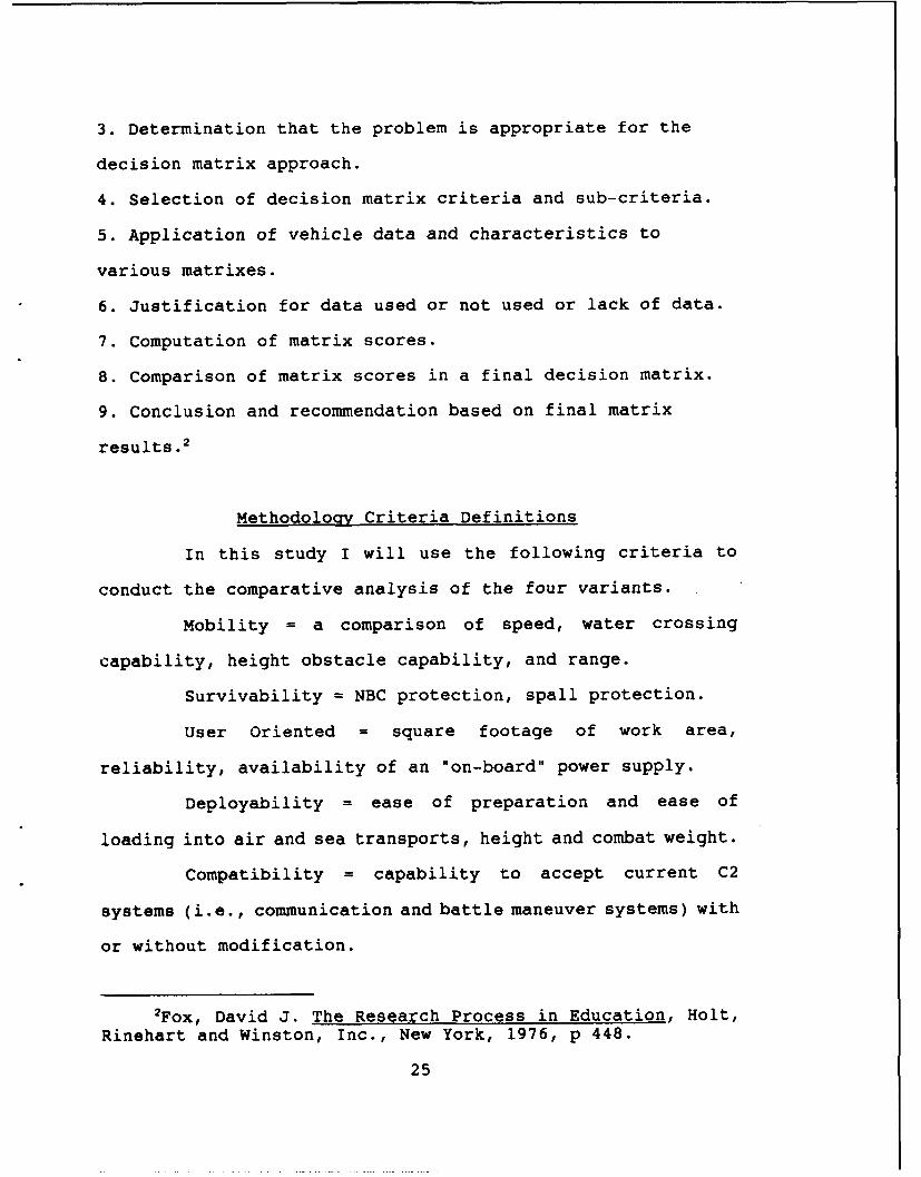
CHAPTER 3METHODOLOGY ............................................... 24
Methodology Criteria Definitions ...................... 25Methodology Model ..................................... 26Weighting Criteria ..................................... 27
CHAPTER 4ANALYSIS OF SELECTED VARIANTS ........................... 29
Vehicle Descriptions and Capabilities ............... .29The HMMWV Variant ................................. ..29HMMWV Description ................................. ..31The HEMTT Variant ................................... 33HEMTT Description .................................... 37The Bradley Variant ........ ....................... 39BRADLEY Description ................................. 40The FUCHS Variant ................................... 44FUCHS Description .................................... 45
v
Comparison of the Four Variants ....................... 48Mobility ............................................ 48Survivability ....................................... 51Compatability/Cost .................................. 54User Oriented ....................................... 55Deployability ....................................... 58
CHAPTER 5RECOMMENDATION AND CONCLUSION ........................... 60
Conclusion ............................................ 63
APPENDIX 1SAMPLE SURVEY ........................................... 66
APPENDIX 2THE LAV-25 .............................................. 67
BIBLIOGRAPHY .............................................. 71
INITIAL DISTRIBUTION LIST ................................. 75
vi
LIST OF FIGURES
Figure No.
CHAPTER 11. Light Cavalry Initial Deployment ................ 8
2. Light Cavalry Follow-On Deployment .............. 9
3. Light Cavalry Regiment ......................... 10
4. Headquarters and Headquarters Troop (LightCavalry Regiment ............................... 11
5. Light Cavalry Squadron (Light CavalryRegiment) ...................................... 12
CHAPTER 21. Tac CP Layout (2nd Bde, 7th ID) ................ 16
2. TOC Internal Layout (2nd Bde, 7th ID) .......... 17
3. MCATF Command and Control Elements ............. 19
4. Assault Amphibious Command Vehicle, LVTC-7 ..... 20
CHAPTER 31. Comparative Analysis Model ..................... 26
2. Interval Scale .................................. 27
CHAPTER 4
1. M997 Maxi-Ambulance ............................ 30
2. Right Rear view of the Maxi-Ambulance .......... 32
3. Oshkosh M977 Heavy Expanded Mobility TacticalTruck (8 X 8) .................................. 33
vii
4. S-783/S-784, S-785/S-786 Expandable Shelters ... 35
5. Left Front View (HEMTT) ........................ 38
6. Right Rear View (HEMTT) ........................ 38
7. Bradley Interior Arrangement ................... 40
8. Bradley Fighting Vehicle (Left Front View) ..... 41
9. Bradley Fight Vehicle (Right Rear View) ........ 42
10. Bradley Vehicle with Swim Barrier Erected ...... 43
11. FUCHS (front, Side, and Rear View) ............. 45
12. FUCHS Interior Arrangement ..................... 46
13. Mobility Matrix ................................ 50
14. Survivability Matrix ........................... 53
15. Compatability/Cost Matrix ...................... 54
16. User Oriented Matrix ........................... 57
17. Deployability Matrix ........................... 59
Chapter 51. Rank Order/Weighting of Criteria ............... 61
2. Best Variant Matrix ............................ 62
APPENDIX 21. The General Motors 8X8 Command and Control
Vehicle ........................................ 67
viii

CHAPTER 1
INTRODUCTION
As the requirements for mobility, flexibility anddispersion of units become increasingly apparent on thebattlefield, the problems of control and coordination aremagnified. The focal point for control and coordinationis the command post, hence it is essential that thisinstallation be capable of effective, continuous operationregardless of circumstances...command posts can no longerafford time previously consumed by facility erection anddismantling. (The command post vehicle) should be capableof cross-country operations, have an amphibious capabilityof crossing inland water obstacles, and be suitable foruse in all climatic conditions. It should be airtransportable in Air Force cargo and assault-type aircraftand...should be transportable by army helicopter usingexternal sling-carry means. The vehicle should contain anintegral power source, separate from that required forvehicular movement. Facilities should include necessaryflooring, siding, and roofing to permit easy, quickassembly of several units. Facilities such as map boards,lights, power outlets, heat, ventilation, and blackoutcapabilities will be built in. The vehicle should providebuilt-in protection from shell fragments and chemical,biological and radiation effects. To the extent feasible,replaces various standard tentage used for commandposts.'
The preceding 4uote sounds like an excellent concept
document for a command post vehicle. Amazingly enough, all
'Mobile Command Post Vehicles. CDOG Project Nr USACGSC57-4, 15 July 1958. Fort Leavenworth Archives #N-18378.128B
1

those previous requirements come from a study conducted in
July of 1958. Unfortunately, the military has been struggling
with the various forms of vehicular command posts ever since
it has had to command and control motorized or vehicular
mounted tactical formations.
This study will attempt to identify a vehicle already
in the Army inventory that might be a better solution for a
command and control vehicle for the Light Cavalry Regiment
rather than the M577 Carrier, Command Post vehicle.
A command post (CP) is the principle facility employed
by the commander to command and control combat operations. A
CP consists of those coordinating and special staff activities
and representatives from supporting Army elements and other
services that may be necessary to carry out operations. 2
Currently, command posts are big, heavily staffed
organizations built around a myriad of vehicle types. Most
command posts, including the current command posts for the
light infantry divisions, are based on some type of transport
vehicle and housed primarily in tents.
The signif i ant problem with this light division design
is that once positioned it is basically immobile. It takes
time to setup and time to take back down. It has no command
and control capability while on-the-move. It therefore
requires duplication in one form or another (ground or
2FM-101-5-1, Operational Terms and Symbols, Hqs,
Department of the Army, Washington, D.C., Oct 1985, p 1-17.
2
airborne "jump" CP) to provide continuity.
Most command posts in the heavy divisions are based on
our current M-577, the Carrier, Command Post. This vehicle,
when compared to the current MIAl and M2/M3 fleet, is too
slow, too unreliable, and too limited. The M577AI/A2 is
unable to keep pace with our current Bradley and M1 fleet. It
lacks protection in an NBC environment and provides little
protection from penetration or spall effects. A U.S. Army
Armor Center report on Operation Desert Storm states, "the
M577 was inadequate as a command and control vehicle during
the operation...the need for new, perhaps Bradley/MLRS based,
C31... vehicle is clear.",3
Even the builder of the M577s, FMC Corporation,
realizes this insufficiency and has proposed yet another
modification and rebuild of the basic M577, currently known as
the XM577A3. It would be inequitable not to mention this
experimental vehicle's proposed capabilities. The XM577A3 has
a combat weight of 31,800 pounds which would rank it less than
the FUCHS, a variant evaluated in this study. It is roughly
the same height as a BRADLEY when reduced (102 inches). It
has a 300-mile range and a maximum speed of 40 mph, which
means it is still slow compared to the BRADLEY or the Ml tank.
FMC promises an interior of 502 cubic feet, "hybrid NBC
protection, air conditioning, bolt-on armor (side, top, and
31Memorandum dtd 24 July 91, U.S. Army Armor Center andFort Knox, Subject: United States Army Armor Center Desert"2hield/Storm Emerging Observations Executive Summary, p 16.
3

belly) and a composite panel spall liner." The proposed price
per vehicle was not available. 4
The current M577 can communicate during movement but
can hardly perform those functions associated with command
post operation, such as administrative functions and planning
once the canvas extensions come down, the lights go o--, e I
the ramps are closed.
The Army needs a command post that can operate on the
move as well as provide a better work area with better
protection and better capabilities. A command and control
system must provide tactical commanders with flexibility and
mobility. CPs must be able to collect, analyze, and present
information rapidly, and communicate orders, coordinate
support, and provide direction to forces. The CP vehicle must
have the characteristics of reliability, survivability,
mobility, speed, and durability. 5 This thesis, will examine
a number of options for a basic command post vehicle. It will
concentrate on vehicles that are already in the field and have
established performance records, repair parts. stockage, and
trained mechanics. It contends that one or more of the four
4FMC Factsheet, The XM577A3, Armored Tactical Command andControl System, FMC Corporation, Ground Systems Division,Santa Clara, California, May 1991.
5Goedkoop, Thomas R. The Task 'Force Tactical OperationCenter: An Organization for Success, Master of Military Artand Science Monograph, US Army Command and General StaffCollege, 1988, p 22.
4
variants used in this study will do a better job than the M-
577 for the Light Cavalry Regiment.
Thesis Statement
Given four currently fielded variants, which vehicle is
best suited as a command and control vehicle for the future
LCR command post? A new organization has been proposed by
the United States Army Armor Center and Fort Knox for the
Light Cavalry Regiment (LCR). This new type of cavalry
regiment will be discussed later in Chapter 2. It is the
command and control vehicle which is the focus of this study.
Scoe
In selecting a base vehicle which is the best for
future LCR operations, the intent of this study is to stay
within the bounds of currently known technologies. All but
one of the variants presented have already been tried in
previous command post tests. Moreover, this study will not
apply any future technologies in the way of command and
control equipment to the selected base vehicle unless it is an
item already selected for fielding.
The study will present a number of CP functions which
will be applied in the analysis of each command post vehicle
5

variant. This study will attempt to define each of these
functions based on my concept of possible LCR deployment
scenarios. The method for the analysis will be fully
explained in Chapter 2.
Definitions, Limitations, and Delimitations
DEFINITIONS
The Light Cavalry Regiment (LCR)
The baseline of this study is the future Light Cavalry
Regiment (LCR). The following paragraphs present the current
state of information regarding this organization. This
information is the most current available at the time of this
writing as provided by the Combined Arms Center for Combat
Developments at Fort Leavenworth.
The current concept for a Light Cavalry Regiment is a
unit that:
-- maintains a quick reaction package to support
contingency operations.
-- deploys immediately after the initial entry force to
rapidly expand security for the airfield/port of debarkation
(APOD). Air superiority is assumed.
-- performs specified cavalry tasks for a corps.
-- uses augmentation to provide METT-T 6 unique
6Considerations used in mission planning, i.e., Mission,Enemy, Terrain (and weather), Troops, and Time available. FM100-5.
6
capabilities (infantry, air defense, etc.)
-- operates with mobility and stealth to cover large
areas and great depths.
-- maximizes use of long range fires (Tactical Air,
Multiple Launch Rocket System (MLRS], Army Tactical Missile
System [ATACMS], and helicopters).
The missions for the LCR as envisioned by the U.S.
Army Combined Arms Center, Combat Developments Directorate
(CAC-CD) include:
-- deployment by air
-- traditional reconnaissance/security missions for
contingency forces to include:
- zone, route, area reconnaissance
-- screen, guard, cover
-- attack, defend, delay
-- Deployment in squadron or task organized packages
(heavy/light/aviation).
-- operation across continuum of military operations
-- strategic deterrence.
Figures 1 and 2 on the following pages illustrate a
proposed light cavalry squadron in the initial deployment
phase and the follow-on deployment. Figures 3-5 depict the
organizations and equipment of the current proposed LCR
structure by CAC-CD. CAC-CD is responsible within the U.S.
Army for designing the equipment and organizational structure
of future units.
7
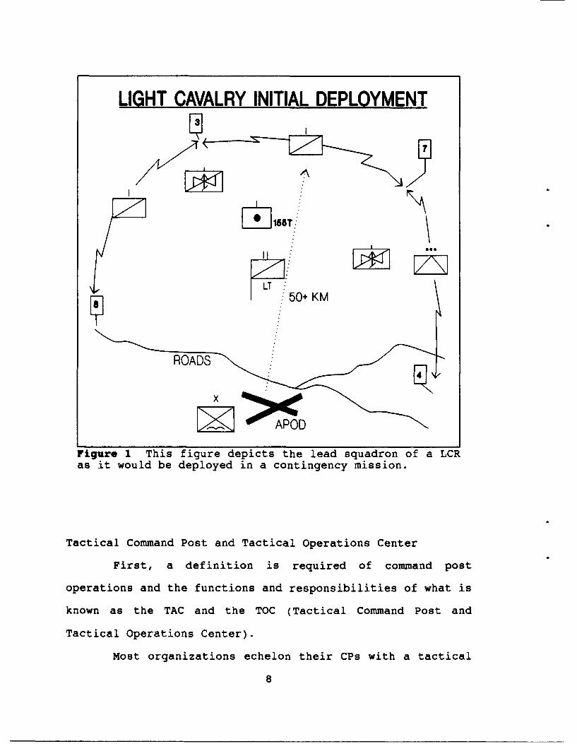
LIGHT CAVALRY INITIAL DEPLOYMENT
W ,
LT50+ KM
ROADS
Figure 1 This figure depicts the lead squadron of a LCRas it would be deployed in a contingency mission.
Tactical Command Post and Tactical Operations Center
First, a definition is required of command post
operations and the functions and responsibilities of what is
known as the TAC and the TOC (Tactical Command Post and
Tactical Operations Center).
Most organizations echelon their CPs with a tactical
8
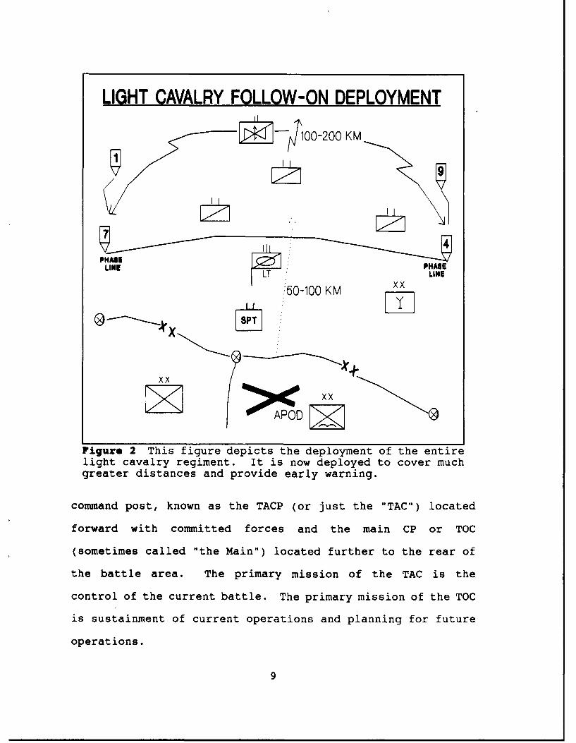
LIGHT CAVALRY FOLLOW-ON DEPLOYMENT
0020KM
PLPINLINE LT x LINE
:50-100 KM xx
x x
Figure 2 This figure depicts the deployment of the entirelight cavalry regiment. It is now deployed to cover muchgreater distances and provide early warning.
command post, known as the TACP (or just the "TAC") located
forward with committed forces and the main CP or TOC
(sometimes called "the Main") located further to the rear of
the battle area. The primary mission of the TAC is the
control of the current battle. The primary mission of the TOC
is sustainment of current operations and planning for future
operations.
9
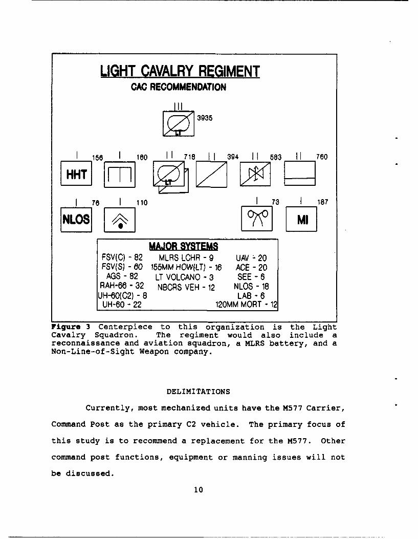
LIGHT CAVALRY REGIMENTCAC RECOMMENDATION
Z 3935
I 166 I 160 II 718 II 394 II 683 II 760aNTI1 78 I 110 1 73 I 187
MAJOR SYSTEMBFSV(C) - 82 MLRS LCHR - 9 UAV :- 20FSV(S) - 60 155MM HOWfLT) - 16 ACE - 20
AGS - 82 LT VOLCANO - 3 SEE - 6RAH-66 - 32 NBCRS VEH - 12 NLOS - 18
UH-60(C2) - 8 LAB - 6UH-60 - 22 120MM MORT - 12
Figure 3 Centerpiece to this organization is the LightCavalry Squadron. The regiment would also include areconnaissance and aviation squadron, a MLRS battery, and aNon-Line-of-Sight Weapon company.
DELIMITATIONS
Currently, most mechanized units have the M577 Carrier,
Command Post as the primary C2 vehicle. The primary focus of
this study is to recommend a replacement for the M577. Other
command post functions, equipment or manning issues will not
be discussed.
10
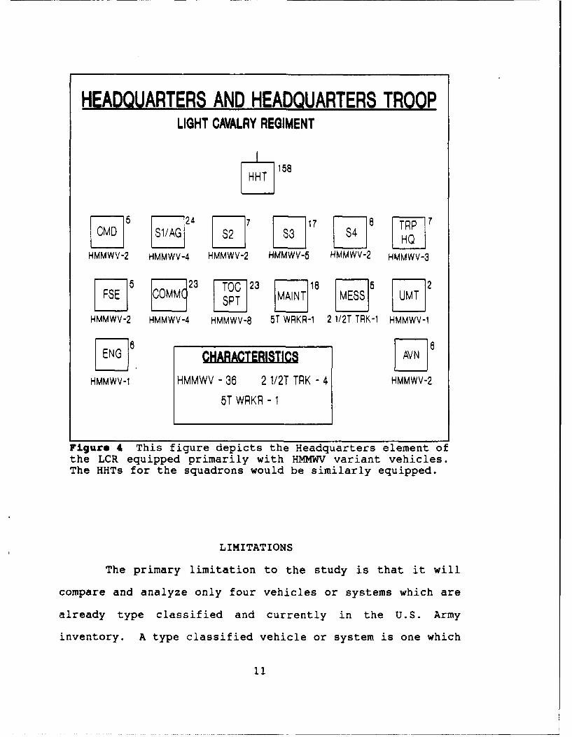
HEADQUARTERS AND HEADQUARTERS TROOPLIGHT CAVALRY REGIMENT
j158
6 4717 HQT-p
HMMWV-2 HMMWV-4 HMMWV-2 HMMWV-5 HMMWV-2 HMMWV-3
l 6 23 TO 23 18 6 12
HMMWV-2 HMMWV-4 HMMWV-8 5T WRKR-1 2 1/2T TRK-1 HMMWV-1
HMMWV-1 HMMWV - 36 2 1/2T TRK - 4 HMMWV-2
5T WRKR - 1
Figure 4 This figure depicts the Headquarters element ofthe LCR equipped primarily with HMMWV variant vehicles.The HHTs for the squadrons would be similarly equipped.
LIMITATIONS
The primary limitation to the study is that it will
compare and analyze only four vehicles or systems which are
already type classified and currently in the U.S. Army
inventory. A type classified vehicle or system is one which
11

LIGHT CAVALRY SQUADRONLIGHT CAVALRY REGIMENT
S718
j 206 108 48 140
FSV(C) - 2 14 AGS 155 HOW (It) - 8HMMWV - 34 13X FSV(C) HMMWV - 83/4T TRL - 17 9XAGS 2 1/2T TRK - 51 1/2T TRK - 11 2X120MM 5T TRK 14WTR TRL - 3 1 1/2T TRL - 65T WRKR - 4 3/4T TRL - 4
1 1/2T TRL - 20 WTR TRL - 1MKT - 3
5T TRK - 15CHARACTERISTICS
FSV(C) - 41 2 1/2T TRK -16RECON-AREA, ZONE, ROUTE AGS - 41 WTR TRL - 4SECURITY-GUARD, SCREEN 165 HOW (LT) - 8 5T WRKR - 4
ECONOMY OF FORCE 120MM MORT - 6 1 1/2T TRL - 26HMMWV - 42 MKT - 33/4 TRL - 21 5T TRK -29
Figure 5 This figure shows the proposed organization andprimary equipment for the light cavalry squadron.
has already been tested to meet the standards of operation as
set by acquisition guidelines and requirements documents.
In discussing this thesis topic with personnel of the Command
and Control Directorate of the Combined Arms Center, upwards
of 24 different variants were proposed for inclusion into this
study. The four selected for this study were based on the
following criteria: currently type classified;
already (or partially) fielded; availability of historical and
12

besic descriptive data; and the ability to present that data
without getting into the dilemma of presenting classified
data.
The four variants which will be used as a basis for
this study are as follows:
-- M997 High Mobility Multipurpose Wheeled Vehicle
(HMMWV)
-- M2A2/M3A2 Bradley Fighting Vehicle (BFV)
-- M985 Heavy Expanded Mobility Tactical Truck (HEMTT)
w/Shelter (Standardized Integrated Command
Post,[SICPS]) [also known as the Functional CP]
-- FOX NBC Recon Vehicle (TPz FUCHS) 6X6
Thesis Outline
The remaining chapters of the thesis are described
below.
Chapter 2: Literature Review. Chapter 2 will review
the current types of light command posts already in use. In
addition a list of documents will be presented with a brief
summary of what information was pertinent for use in this
study.
Chapter 3: Methodology. The general plan to meet
objectives includes a listing of the various functional
requirements of a command post vehicle and apply those
elements in a matrix against four variants as candidates for
a future command post vehicle. Assumptions and the parameters
13
of the study are presented. A survey was conducted to
determine the 'weighting' of criteria for the decision support
matrix. A reommendation will be made based on the matrix.
Chapter 4: Analysis. Chapter 4 will present a general
discussion of the operational characteristics of each of the
candidate vehicles. Each vehicle will be discussed separately
first in regard to the scope, limitations, and parameters
previously mentioned. A short discussion will disclose the
rationale for assignment of base scores in the comparison
matrix prior to the application of weighted criteria.
Chapter 5: Conclusion. The conclusion from
this study is be to recommend a command and control vehicle
for the LCR that is best equipped for the command and control
missions that a LCR may be tasked to perform as part of a
contingency corps with global contingencies. Future army
units will have to be highly flexible in their ability to
focus on a large number of different types of threat and
environments. This study will provide the basis for the
command post base vehicle.
14

CHAPTER 2
LITERATURE REVIEW
The purpose of the literature review is to present
other information relative to the problem and to present
information sources and research information which are used in
the completion of this study. Having completed research, the
data collected will be applied to a selected methodology which
results in formulation of a conclusion and recommendation.
For the purposes of this study I will first present
some examples of a current light brigade size command post.
Secondly, I will summarize the research and information
sources which I used in the comparison of selected variants.
Other Current "Light Command Posts"
U.S. Army Light Infantry Division
A command post currently in existence which most
closely models the apparent needs of a future light cavalry
regiment is the command post organization of a brigade in a
light infantry division. Researching this type of command
15
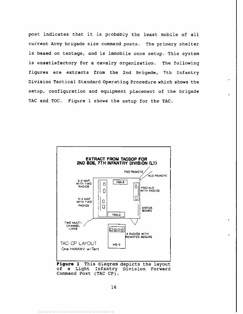
post indicates that it is probably the least mobile of all
current Army brigade size command posts. The primary shelter
is based on tentage, and is immobile once setup. This system
is unsatisfactory for a cavalry organization. The following
figures are extracts from the 2nd Brigade, 7th Infantry
Division Tactical Standard Operating Procedure which shows the
setup, configuration and equipment placement of the brigade
TAC and TOC. Figure 1 shows the setup for the TAC.
EXTRACT FROM TACSOP FOR2ND BDE, 7TH INFANTRY DIVISION (LI)
FSO REMOTE
S -2 M A P _ _ _ _
R O
WITH TWO 5 TLRADIOS FSO/ALO
E WITH RADIOS
S-3 MAPWITH TWO "1
RADIOS 11 STATUS
BOARD
TWO MULTi-
B
CHANNELLINES
4 RADIOS WITHEMOTES SECURE
TAO OP LAYOUT HO-3
One HMMWV w/Tent
Figure 1 This diagram depicts the layoutof a Light Infantry Division ForwardCommand Post (TAC CP).
16

This command post configuration is transported by HMMWVs and
3/4 ton trailers. It has little capability to function on the
move. This type of setup suffic- 'nr the light infantry
brigade. Once the brigade is in place on the ground it is
relatively immobile so there is not a requirement for a mobile
C2 capability. This CP is based primarily on the expandable
tent version of the Standardized Integrated Command Post
(SICPS).
Figure 2 depicts the TOC operation which again is
totally housed in expandable tents.
EXTRACT FROM TACSOP FOR2ND 1JDE, TTH INFANTRY DIVISION (LT)
GENERATO TOO INTERNAL LAYOUTExit ; BASED ON EXPANDABLE TENTS.r r 2
CPS.1E I I SNTEL NCO
FSO/PEMBASS
WIN ýCOHAIRj _ BarEFINO 8OARD
-AJEN T RAN CE
Figure 2 This figure depicts the layoutof a Light Infantry Division Main CommandPost.
17

The Marine Command Post
The Marine Corps Mechanized Combined Arms Task Force
(MCATF) is built around battalion size maneuver elements.
Armor and infantry units comprise the task force, dependent
upon the mission and area of operations.' This force has a
mission profile similiar to missions that the LCR is expected
to carry out. The MCATF is a force which is expected to
conduct contingency operations in any part of the world on
short notice. For that reason it is interesting to conduct a
short review of the MCATF's command and control structure and
procedures.
A regimental-sized MCATF will consist of at least two
battalion-siZed maneuver elements. The principle forces of a
MCATF are tanks, infantry mounted in amphibious assault
vehicles (AAVs) and artillery.
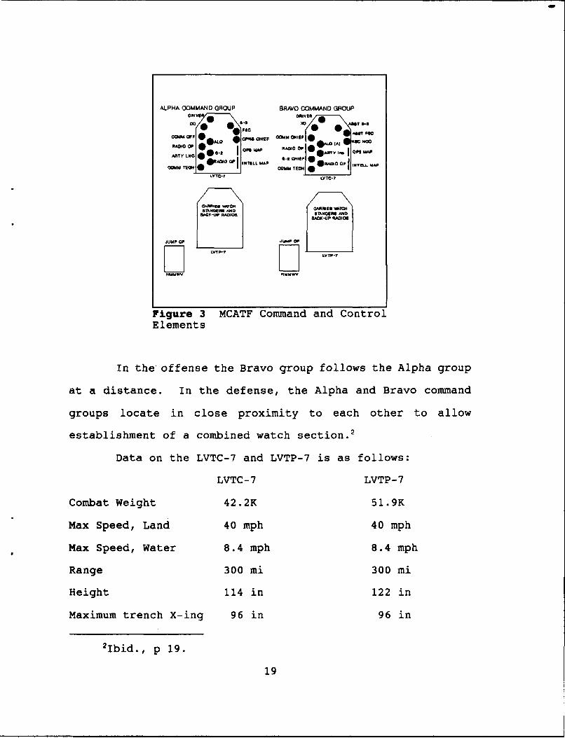
The command and control element for a MCATF is made up
of six principle vehicles, two Assault Amphibian Personnel and
Cargo Carriers (LVTP-7), two Assault Amphibious Command
Vehicles (LVTC-7), and two HMMWVs. This arrangement gives the
command group the capability to operate as two separate
command groups designated as the ALPHA Command Group and the
BRAVO Command Group. Each group is made up of three vehicles.
A LVTC-7 is the primary vehicle. The LVTP-7 and HMMWV carry
personnel and equipment as shown on the following page.
'Marine Corps Institute, Mechanized Operations,Amphibious Warfare School, Marine Barracks, Washington, D.C.,MCI 7509B, 1983, p 2.
18
ALPHA COMMAND GROUP BRAVO OMMANO GROUP
OMMO OP OMM
RADIO OP *@0 *jIL EA.) akis 1D6004S : A
AigurT MA MCAT RADIO OF an CoP MAP
*RADIO OP IITELL MAP group @R^o00 OP MT- APCOMMJ COMM TECH
LVTC- 7 VLYTTT
"I'TonE AND CARRIES VAT04MACK-UP RADIOS UDR N
LACK-UP RADIOSN
JUMP CP JUMP OP
NMMV IAMMWVO
Figure 3 MCATF Command and ControlElements
In the offense the Bravo group follows the Alpha group
at a distance. In the defense, the Alpha and Bravo command
groups locate in close proximity to each other to allow
establishment of a combined watch section.'
Data on the LVTC-7 and LVTP-7 is as follows:
LVTC-7 LVTP-7
Combat Weight 42.2K 51.9K
Max Speed, Land 40 mph 40 mph
Max Speed, Water 8.4 mph 8.4 mph
Range 300 mi 300 mi
Height 114 in 122 in
Maximum trench X-ing 96 in 96 in
2Ibid., p 19.
19

Both vehicles have approximately 462 cubic foot of space in
the cargo/troop compartment area (14ft X 5.5ft X 6ft).
ASSAULT AMPHIBIOUS COMMAND VEHICLE, LVTC-7
Figure 4 This a silhouette view of the LVTC-7 vehicle used bythe U.S. Marine Corps as a command post vehicle.
In units equipped with the LAV-25 the LAV Command and
Control variant is used. A discussion on this vehicle can be
found in Appendix 2.
Research and Information Sources
The US Army Armor Center and Fort Knox published a
report (May 91) which lays out the broad base design of the
future LCP. Little has been mentioned regarding the design of
the headquarters element of the LCR and the type of v-ehicle
that will comprise the command post. Major General Thomas
Foley, Commanding General of the U.S. Army Armor Center and
Fort Knox discusses these concepts in Armor 2000 - A Balanced
20
Force for the Army of the Future. The Combat Development
Branch of the Combined Arms Center (CAC-CD) has some studies
which were completed during the mid-1980s that dealt primarily
with the design of a light armor battalion and the CS\CSS
units required to support it. A concept test for improving
command and control was also conducted in between 1986 and
1987 by Fort Knox. This test was titled, Command and Control
Vehicle Concept Program - Command and Control Enhancements
Force Development Testing and Experimentation. The results of
this test discuss the application of various modifications to
the M1 tank, Bradley Fighting Vehicle, the M577 Command Post
Carrier, and the M1009 Commercial Utility Cargo Vehicle. Many
of the findings were useful in the selection of the four
variants used in this study.
The results from a report entitled Division Command
Post Test conducted at Fort Hood in 1975 also provided
insights as why there is a need for better mobility, and
surviva.'lity in CP design.
A few published monographs from the School of Advanced
Military Studies at Fort Leavenworth provided information
discussing the doctrinal shortfalls in command and control of
reconnaissance missions of armored cavalry.
Approximately 25 works have been identified by the
Combined Arms Research Library that discuss aspects of the
structure of command and control systems at the tactical
level. These works do not address the issue of command and
21
control vehicle variants directly, but serve as background
material in command post operation and the information needs
of the commander and staff.
Several Jane's series books on combat vehicles, combat
support vehicles and command and control systems were very
helpful in providing some of the basic data used in comparing
the variants.
Current MTOEs and after action reports that discuss the
organization, manning and deployment of the "light" and
"airborne" command posts are available at the U.S. Army's
Center for Army Lessons Learned (CALL). The Desert Storm
Special Study Project Archives have a variety of reports which
discuss operational problems of the two armored cavalry
regiments deployed during Operation Desert Storm. These
monographs, MTOE designs as provided by Combined Arms Center,
Combat Developments (CAC-CD), as well as reports from Desert
Storm provide the basis for analysis in order to identify
operational shortfalls and discuss possible solutions.
The technical data for this study was extracted from a
variety of U.S. Army Technical Manuals (TMs) which were
available for each of the specific vehicle variants.
Reports from various units participating in Desert
Storm, briefing packages on Desert Storm and emerging insights
from the Total Armor Force Management Office at Fort Knox were
key to the focus of this study.
Marine technical bulletins and the manufacturer's
22

Operator Handbook for the LAV-25 dated 30 May 1984 were
helpful in the development of the information presented in
Appendix 2.
Finally, technical information provided by the Army
Material Command (AMC), and the FMC Corporation in the form of
fact sheets and information papers on the Standardized
Integrated Command Posts (SICPs) and the German FUCHS vehicle
were key to two of the variants used in this study.
23
CHAPTER 3
METHODOLOGY
It is a truth beyond argument that full andaccurate information becomes most vital at the point ofimpact, for unless it is correctly applied there, thewisest plans of the ablest general will likely fail.'
S.L.A. Marshall
The methodology used in this study is primarily a
comparison of four different vehicle variants for use in the
C2 role of a Light Cavalry Regiment (LCR). Comparative
matrixes were obtained from the Army Acquisition Course at the
U.S. Army Logistics Management College at Fort Lee which were
used in the selection of vehicles during the Army acquisition
process.
The process of my research and analysis is as follows:
1. Determination of a problem or information void.
2. Statement of research problem.
'Marshall, S.L.A., Men Against Fire, Washington: Infantry
Journal, 1947, quote is attributed to this work.
24
3. Determination that the problem is appropriate for the
decision matrix approach.
4. Selection of decision matrix criteria and sub-criteria.
5. Application of vehicle data and characteristics to
various matrixes.
6. Justification for data used or not used or lack of data.
7. Computation of matrix scores.
8. Comparison of matrix scores in a final decision matrix.
9. Conclusion and recommendation based on final matrix
results.2
Methodology Criteria Definitions
In this study I will use the following criteria to
conduct the comparative analysis of the four variants.
Mobility = a comparison of speed, water crossing
capability, height obstacle capability, and range.
Survivability = NBC protection, spall protection.
User Oriented = square footage of work area,
reliability, availability of an "on-board" power supply.
Deployability = ease of preparation and ease of
loading into air and sea transports, height and combat weight.
Compatibility = capability to accept current C2
systems (i.e. , communication and battle maneuver systems) with
or without modification.
2Fox, David J. The Research Process in Education, Holt,
Rinehart and Winston, Inc., New York, 1976, p 448.
25
Cost = a comparison of purchase price of each vehicle.
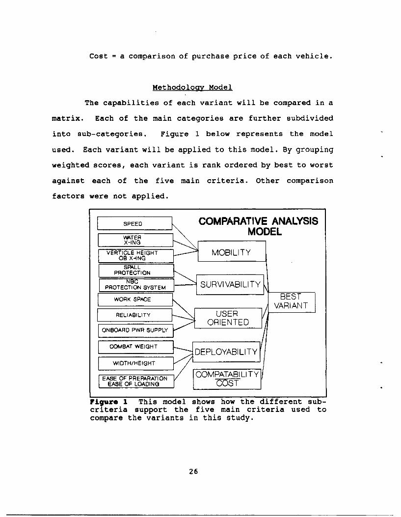
Methodology Model
The capabilities of each variant will be compared in a
matrix. Each of the main categories are further subdivided
into sub-categories. Figure 1 below represents the model
used. Each variant will be applied to this model. By grouping
weighted scores, each variant is rank ordered by best to worst
against each of the five main criteria. Other comparison
factors were not applied.
SPEED • COMPARATIVE ANALYSISM•TER
X-ING
VER ICOLE HEIGHT I MOBILITYE8 XOING
SPALL I
PROTECTI ON
NBC SRIVB ITPROTECTION SURVVABLIT
WORK SPACE BEST
RELIABILITY USERVAIN
ONBO---RD PWR SUPPLY "...OENE
COMBAT WEIGHT DEPLOYABILITY
,,IDTH/HEIGHTEASE OF PREPARAT, ON CO/ TBIIT
EASE OF LOADING [V COST
Figure I This model shows how the different sub-criteria support the five main criteria used tocompare the variants in this study.
26
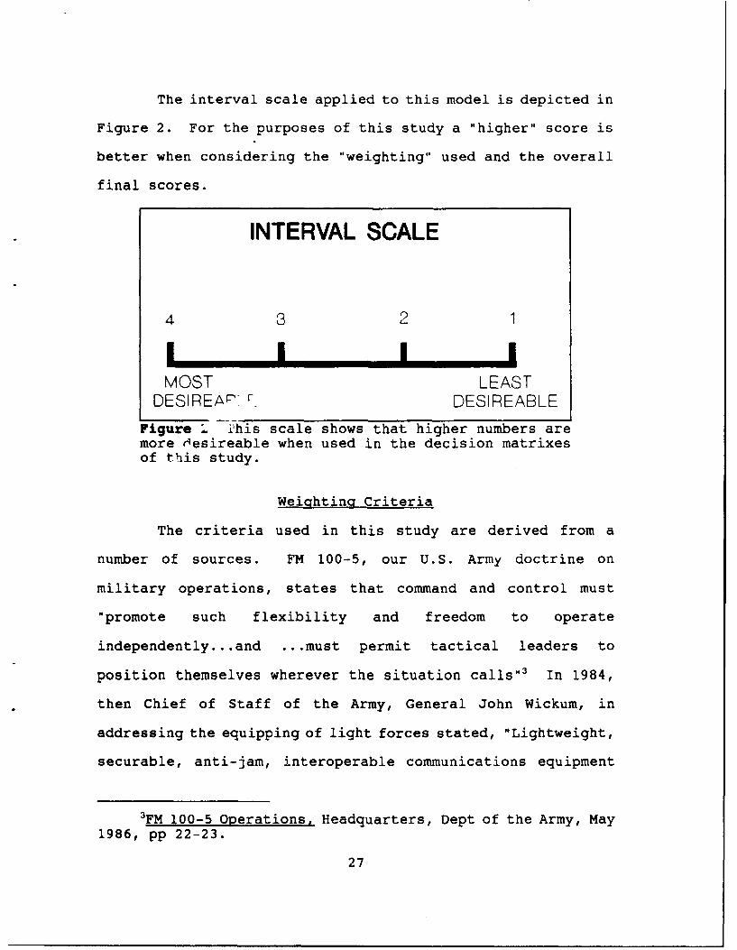
The interval scale applied to this model is depicted in
Figure 2. For the purposes of this study a "higher" score is
better when considering the "weighting" used and the overall
final scores.
INTERVAL SCALE
4 3 2I i i iMOST LEAST
DESIREAr'. DESIREABLE
Figure k 2his scale shows that higher numbers aremore Hesireable when used in the decision matrixesof this study.
Weighting Criteria
The criteria used in this study are derived from a
number of sources. FM 100-5, our U.S. Army doctrine on
military operations, states that command and control must
"promote such flexibility and freedom to operate
independently...and ... must permit tactical leaders to
position themselves wherever the situation calls"3 In 1984,
then Chief of Staff of the Army, General John Wickum, in
addressing the equipping of light forces stated, "Lightweight,
securable, anti-jam, interoperable communications equipment
3FM 100-5 Operations, Headquarters, Dept of the Army, May
1986, pp 22-23.
27
will be needed to support decentralized, independent
operations. Appropriate design criteria will include: light,
high mobility vehicles, high reliability.. .and longer range. "'4
These sources and others drove the selection of the
five main criteria listed in Figure 1. A survey was conducted
at Fort Leavenworth, among staff college students and faculty,
in January of 1992, to determine which of the five criteria
were most important to users in the field. (See Appendix 1
Sample Survey.) Combat arms, combat support and combat
service support officers who had experience in our current C2
vehicles were asked to rank order from "most important" to
"least important" the five major criteria while comparing
their application to a possible future command and control
vehicle. The results of this poll will be discussed in
Chapter 5.
4Chief of Staff, US Army, White Paper 1984, LightInfantry Divisions, Headquarters, Dept of the Army,Washington, D.C., May 1984, p 5.
28
CHAPTER 4
ANALYSIS OF SELECTED VARIANTS
In this chapter the effectiveness and potential
utility of each of the four command and control variants
will be assessed. The assessment of each vehicle variant
will be preceded by a technical description of the variant
and a listing of it's various capabilities.
Assessment will be performed by comparing the
variants in a series of matrixes as explained in Chapter 3.
After each of the variants have been analyzed and a base
score determined, the final step will be to combine the base
score for each of the variants into a final decision matrix.
The vehicle with the best overall score will provide the
basis for final recommendation and conclusions.
Vehicle Descriptions and Capabilities
The HMMWV Variant
The High Mobility Multipurpose Wheeled Vehicle or
HMMWV has a number of models which were considered for the
purpose of this study. Communication variants are already
29
fielded extensively throughout the Army which consist of a
S-250 Shelter mounted on the back of the M1037 or M!042
model HMMWV. The only difference between these two models is
a winch mounted on the front of the M1042 model. Currently,
the S-250 Shelters are equipped to function as switchboards,
or Subscriber Entry Point nodes (SENS nodes) for the
Multiple Subscriber Network (MSE). This model was not
selected because the shelter currently is not equipped with
an NBC system nor is there a kit available to increase
ballistic protection.'
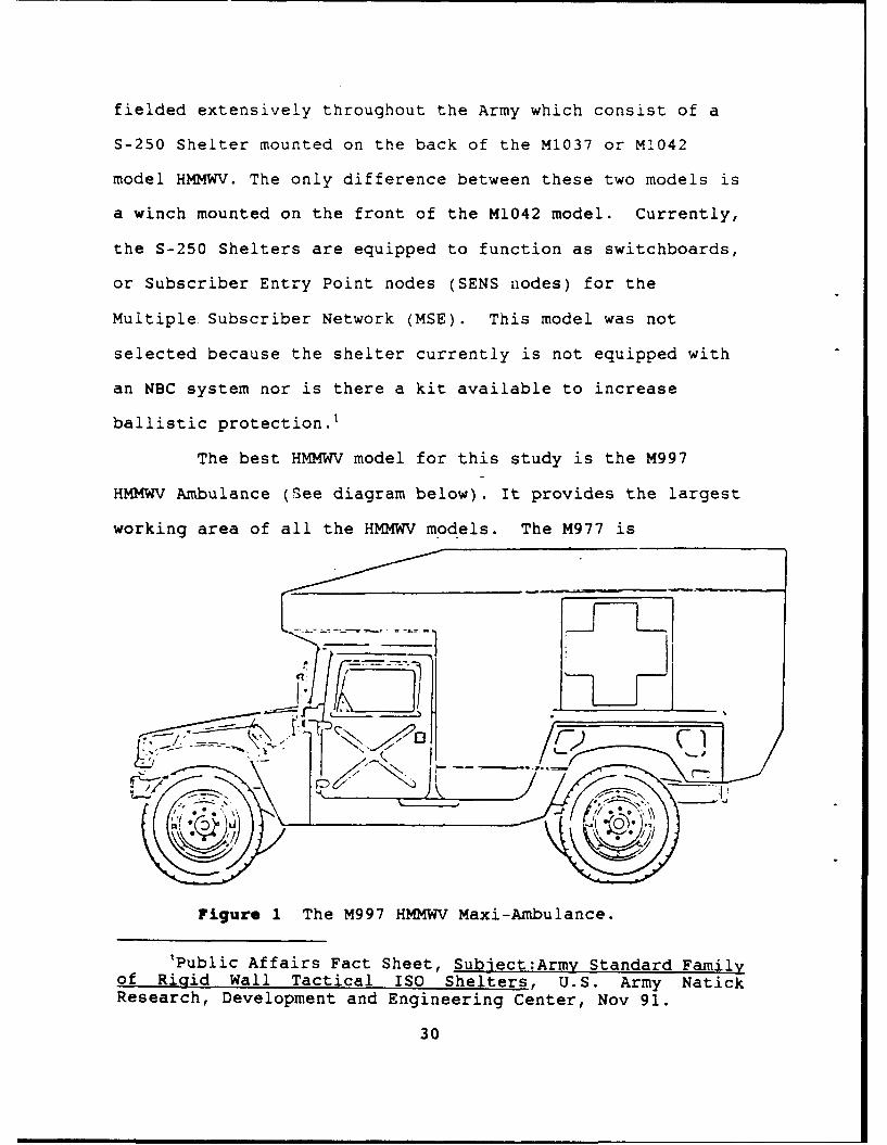
The best HMMWV model for this study is the M997
HMMWV Ambulance (See diagram below). It provides the largest
working area of all the HMMWV models. The M977 is
Figure 1 The M997 HMMWV Maxi-Ambulance.
'Public Affairs Fact Sheet, Subject:Army Standard Familyof Riqid Wall Tactical ISO Shelters, U.S. Army NatickResearch, Development and Engineering Center, Nov 91.
30
equipped with a NBC gas-particulate system and air
conditioning system. The current ambulance body is made of
the same kevlar material found in the standard armored HMMWV
body. This kevlar body provides limited protection from
shrapnel and small arms penetration.
HMMWV Description
The HMMWV is a four wheel vehicle which has a drive
train in the midships position allowing the front
differential to be raised. This, together with the geared
hubs, provides a ground clearance of 24 inches. To reduce
life cycle and initial procurement costs, standard
automotive components are used wherever possible, as in the
engine, transmission, transfer case, brakes and steering.
The independent suspension, front and rear, gives
good maneuverability, ease of handling and part commonality.
The geared hubs give .406m all-round ground clearance
incorporating raised axles for high speed operations on road
and cross country. The hubs also provide a 1.92:1 torque
output multiplication at the ground.
The HMMWV will accelerate from a standstill to 48
km/h in seven seconds and from a standstill to 80 km/h in 20
seconds. Three HMMWVs can be carried in a C-130 Hercules
transport aircraft, six in a C-141B and 15 in a C-5A
31
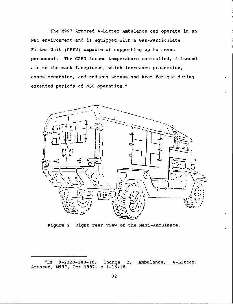
The M997 Armored 4-Litter Ambulance can operate in an
NBC environment and is equipped with a Gas-Particulate
Filter Unit (GPFU) capable of supporting up to seven
personnel. The GPFU forces temperature controlled, filtered
air to the mask facepieces, which increases protection,
eases breathing, and reduces stress and heat fatigue during
extended periods of NBC operation. 3
-GN
7_1
/ .. . i I -_ 1 . ..-. lI. --"I-
t
_ _ CF• -
C .Iff
Figure 2 Right rear view of the Maxi-Ambulance.
3TM 9-2320-280-10, Change 2, Ambulance, 4-LittersArmored, M997, Oct 1987, p 1-16/18.
32
The HEMTT Variant
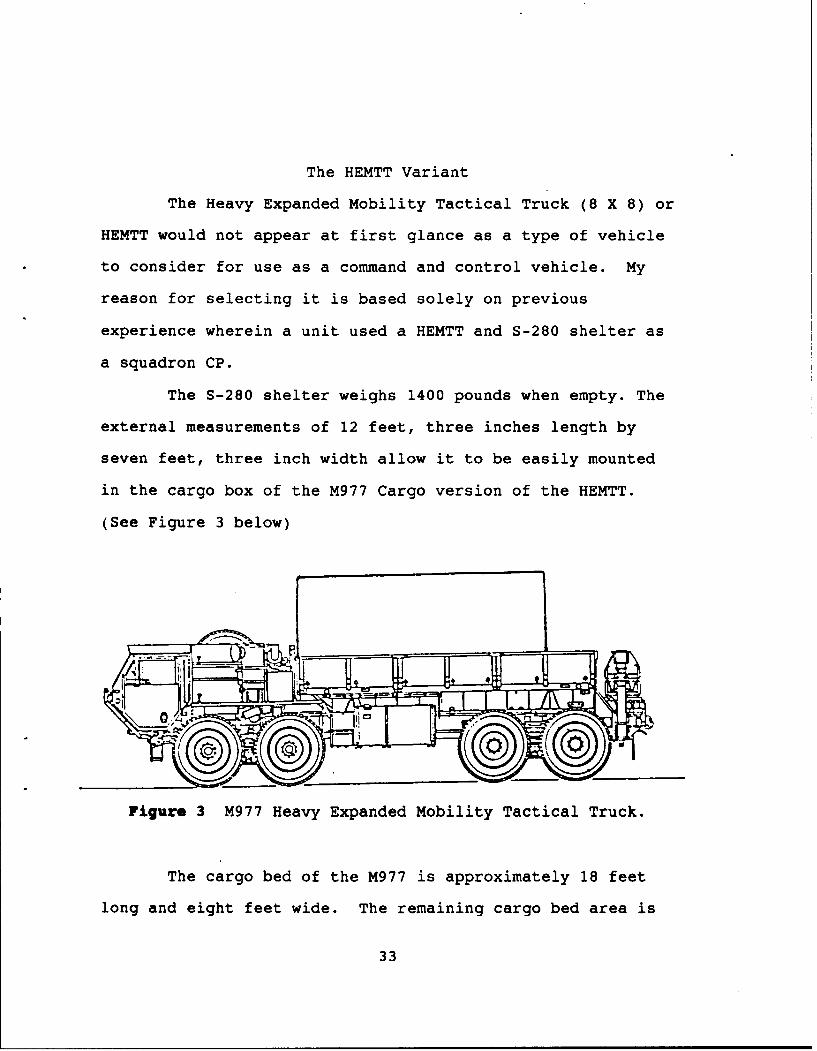
The Heavy Expanded Mobility Tactical Truck (8 X 8) or
HEMTT would not appear at first glance as a type of vehicle
to consider for use as a command and control vehicle. My
reason for selecting it is based solely on previous
experience wherein a unit used a HEMTT and S-280 shelter as
a squadron CP.
The S-280 shelter weighs 1400 pounds when empty. The
external measurements of 12 feet, three inches length by
seven feet, three inch width allow it to be easily mounted
in the cargo box of the M977 Cargo version of the HEMTT.
(See Figure 3 below)
Figure 3 M977 Heavy Expanded Mobility Tactical Truck.
The cargo bed of the M977 is approximately 18 feet
long and eight feet wide. The remaining cargo bed area is
33
used to mount a 3KW or 5KW generator (as an on-board power
supply) and to carry the personal gear (TA-50) of on-board
personnel.
Another feature is that the boom can be used as a
quick deploying antenna by attaching two or three lengths of
a normal antenna mast and the head and then raising the boom
to the vertical ý7sition fully extended.
The current S-280 Shelter is capable of being
shielded by the addition of a modification kit to provide at
least 60db attenuation to electric and magnetic fields and
to plane waves in the frequency range from 0.15MHz to
10,000MHz. Bolt on kevlar armor could be added to this
shelter to increase ballistic protection. 4
This type of shelter is currently in use by many
units for electrical test and repair facilities and is
normally mounted on the 5 ton series truck.
Development of these type of shelters has resulted in
the recent fielding of a new series of containers which meet
standards of "International Organization for
Standardization" (ISO). These ISO shelters have exterior
dimensions of eight feet by eight feet by 20 feet when in
their transportation mode. These shelters are for use in
4public Affairs Fact Sheet, Subject: Army StandardFamily of RiQid Wall Tactical Shelters, S-280/G Shelter, U.S.Army Natick Research, Development and Engineering Center, Nov91.
34

situations requiring highly mobile, environmentally
controlled, work-in/live-in space.
The shelter panels are sandwich construction of
nonmetallic honeycomb core thermally bonded with facings of
aluminum skins which allow the users to mount hardware or
equipment anywhere on the panels. Each shelter has built-in
systems for three phase electrical distribution, internal
fluorescent lights, an external area light and interface for
external environmental control units. Each is equipped with
leveling jacks and can be erected in the field without
special tools. The shelter comes in three versions;
nonexpandable (S-781 or S-782), one-side expandable (S-783
or S-784), or two side expandable (S-785 or S-786).
There are two model numbers of each type, the lower
number designating a 60 amp system and the higher
designating a 100 amp system. The nonexpandable version has
an empty weight of 3,900 pounds and a floor area of 145
5." • ".." *.. - ... * ••:•V. *: 1,
Figure 4 S-783/S-784, S-785/S-786 Expandable Shelter.
35

expandable models weigh 6,900 pounds and have a floor area
of 390 square feet. (See Figure 4).
U.S. Army Natick RD&E Center is further developing
the functional capacities of these shelters by developing
connecting passageways, hardwall extension kits. To further
enhance capabilities upgrades are available to counter
specific threats which include chemical protection,
electromagnetic interference (EMI) protection,
electromagnetic pulse (EMP) protection, ballistic
protection, and blast and thermal protection. 5
No reference was found to substantiate whether or not
one of the new ISO shelters had ever been mounted on the bed
of a HEMTT M977. The overall length of the ISO shelter (20
feet) exceeds the current bed length (18 feet) of the M977.
However, this additional length could be accommodated by
removing the front and rear cargo bed side wall panels and
dismounting the boom assembly. Available power telescoping
antennas could be used in lieu of the boom assembly for
antenna erection.
Due to the increased potential for protection,
increased work area, and expansion this type of shelter
provides, I determined the HEMTT vehicle would be a solid
candidate for a command and control vehicle if it carries
one of the new ISO shelters. Even with the smaller S-280
5Public Affairs Fact Sheet, Subject: Army StandardFamily of Rigid WAll Tactical ISO Shelters, U.S. Army NatickResearch, Development and Engineering Center, Nov 91.
36
candidate for a command and control vehicle if it carries
one of the new ISO shelters. Even with the smaller S-280
model shelter, the HEMTT is a solid option.
For the purposes of this study the HEMTT C2 variant
will be considered to be carrying Non-expandable S782/G (100
amp) shelter. Although the larger work area provided by one
of the expanding versions would have been preferred, the
non-expanding models were chosen, due to the need to
restrict weight wherever possible.
HEMMT Description
The first prototype for the HEMTT was completed in
December of 1981 as a replacement for the M520 GOER. The
first production vehicles were delivered in September of
1982. The vehicle makes extensive use of standard
commercial automotive components including an Oshkosh truck
cab, standard eight-cylinder diesel engine and a standard
four-speed automatic transmission.
The chassis is formed of channel bolted construction
with heavy duty front bumper and skid plate, external
hydraulic connection, service and emergency air brake
connection, slave start connection and trailer electrical
connector. (See front below and rear view Figure 5 and 6,
respectively.)
37

Figure 5 M977 Left Front View.
_, if . •:- . r;A x..~t~rr
Figure 6 M977 Right Rear View.
The rear axles are Eaton DS-480 single reduction type
with driver controlled differential. The engine is a
38
Detroit Diesel 8V-92TA, V-8, 2 stroke, 12.06 liter diesel
developing 445 hp at 2100 rpm. The M977 Cargo truck is the
basic member of the HEMTT series with a light duty material
handling crane at the very rear. The cargo area is 18 feet
long with drop sides.'
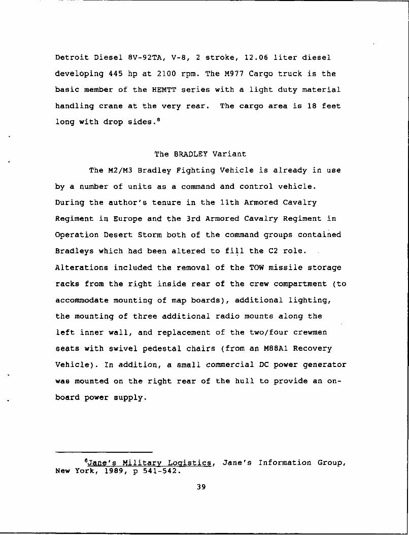
The BRADLEY Variant
The M2/M3 Bradley Fighting Vehicle is already in use
by a number of units as a command and control vehicle.
During the author's tenure in the 11th Armored Cavalry
Regiment in Europe and the 3rd Armored Cavalry Regiment in
Operation Desert Storm both of the command groups contained
Bradleys which had been altered to fill the C2 role.
Alterations included the removal of the TOW missile storage
racks from the right inside rear of the crew compartment (to
accommodate mounting of map boards), additional lighting,
the mounting of three additional radio mounts along the
left inner wall, and replacement of the two/four crewmen
seats with swivel pedestal chairs (from an M88A1 Recovery
Vehicle). In addition, a small commercial DC power generator
was mounted on the right rear of the hull to provide an on-
board power supply.
6Jane's Military Logistics, Jane's Information Group,
New York, 1989, p 541-542.
39

BRADLEY INTERIOR ARRANGEMENT
hlm WI" ile.
Figure 7 BRADLEY top view andinterior arrangement.
Of all the variants considered in this study, the rradley
is the most heavily armed and most capable of providing the
LCR and subordinate squadron commanders a command and
control vehicle with the best self-defense capability.
BRADLEY Description
The first production Bradley Fighting Vehicles were
delivered to the Army in July of 1982. The hull of the
fighting vehicle is made of all-welded aluminum armor with
spaced laminate armor fitted to the hull, sides and rear.
The driver sits at the front of the vehicle on the
left and has a single piece hatch cover. Periscopes provide
the driver with vision while the hatch is secured. The
center front periscope can be replaced by an AN/VVS-2
40
passive night periscope for night operations. The engine
compartment is to the right of the driver and houses a
Cummins VTA A-903T turbo-charged 8-cylinder diesel
developing 500 hp at 2600 rpm (newer models develop 600 hp).
The engine is coupled to a General Electric HMPT-500
hydro-mechanical transmission that has three different speed
ranges. The vehicle has a Halon fixed fire extinguisher
system. Main armament consists of a McDonnell Douglas
Helicopter Company M242 25mm Chain Gun with a 7.62 M240C
machine gun mounted coaxially to the right of the main gun.
The 25mm cannon is dual feed and the gunner can select
single shots, 100 or 200 rpm rates of fire.
HATCHCOVER
ARMOR PLATE
INTAKE GRILLE SCREEN
TRIM VANE -"''" •
ý4 IDLER
k.TRACK
ROAD WHEEL
HEADLIGHTASSEMBLY EXTERIOR FIRE
DRIVE SUPPRESSION
Figure 8 Left front view of the M2/M3 BRADLEY vehicle.
41
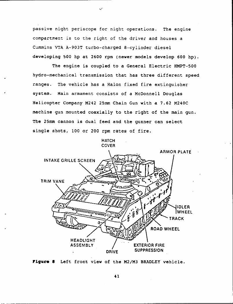
The turret has a 360-degree electric traverse and the
weapons can be elevated from -10 to +60 degrees. Mounted on
the gunners side of the vehicle is the TOW sub-system. A
single-piece hatch cover that opens to the rear is located
over the troop compartment. On the rear of the vehicle is a
large hydraulically operated ramp which has an integral door
in the left side.
CARGO HATCH COVER
HATCH COVERPERISCOPE- FUEL
M2AI, M3AI ONLY FILLER
REAR COVER
STOWAGEB0X ENGINE
BOX EXHAUSTTAILLIGHT EXAS
I DEFLECTOR
RAMP "EXHAUST
ACCESS TWING GRILLE
DOOR PINTLE RAMP
TRAILER PORTS - EXTERIOR FIRERECEPTACLE M2, M2A1 SUPPRESSION
ONLY HANDLE-CREWCOMPARTMENT
Figure 9 Right rear view of the M2/M3 BRADLEY vehicle.
The Bradley has a central gas particulate filter
system for the commander, gunner and driver, but personnel
42

in the rear compartment have to wear individual protective
masks. The Bradley does not have an over-pressure system.
The Bradley is fully amphibious being propelled in
the water by its tracks. Preparation time is required prior
to swimming the vehicle in orde- '-o erect a water barrier
which is normally stowed in a rolled position along the top
of the side skirts. The application of additional armor
protection makes the Bradley too heavy for the current
flotation curtain. (See Figure 10 below of a Bradley with
the Water Barrier erected).
--- . • ------
• "• • ",, ~. N .,. .--.
WATERBARRIER
Figure 10 BRADLEY vehicle with swim barrier erected.
The Bradley is air transportable in the C-141 and C5A
however, when being airlifted in the C-141 Starlifter the
head of the gunner's integral sight and the skirt plates are
removed and all road arm positions (6 on each side) are
snubbed in the up position using steel cables. Although the
combat weight of the Bradley M3A2 is 66,000 pounds it can be
reduced to 44,000 pounds for air transport by the removal of
the add-on armor and side skirting.
43

and revised ammunition stowage. Other improvements are
planned. Tests have been underway at the U.S. Aimy
Materials Technology Laboratory (MTL) since September of
1986 for the construction of a molded thick laminate
composite (reinforced plastic) hull based on the Bradley
7chassis.
The FUCHS Variant
Of the four variants in this study, only the FUCHs
Transportpanzer 1, (Armored Personnel Carrier), was
specifically developed as a command and control vehicle.
The U.S. Army does not have this model in it's inventory.
Since 1989, the U.S. Army has purchased a number of the
FUCHs vehicles but only of the NBC Reconnaissance version,
known in the U.S. Army's nomenclature as the NBC
Reconnaissance System (NBCRS or FUCHS NBCRS) or as the
"FOX". The NBCRS is an integrated system capable of
detecting, identifying, and marking areas of nuclear,
biological, and chemical contamination. 8
The German Army designation for the FUCHS C2 version
is the FueFu (FUCHS + Fuhre (for commander or leader)). The
vehicle has a 5kw generator in the left wing of the rear
7Jane's Armour and Artillery, 1988-89, Jane's InformationGroup, New York, 1988, p 396-400.
8Matthews, George F., Initial TransportabilityEngineerinQ Analysis of the Nuclear-Biological-ChemicalReconnaissance System (NBCRS) FUCHS TPZ1 Version, MilitaryTraffic Management Command, Nov 1986, p 1.
44
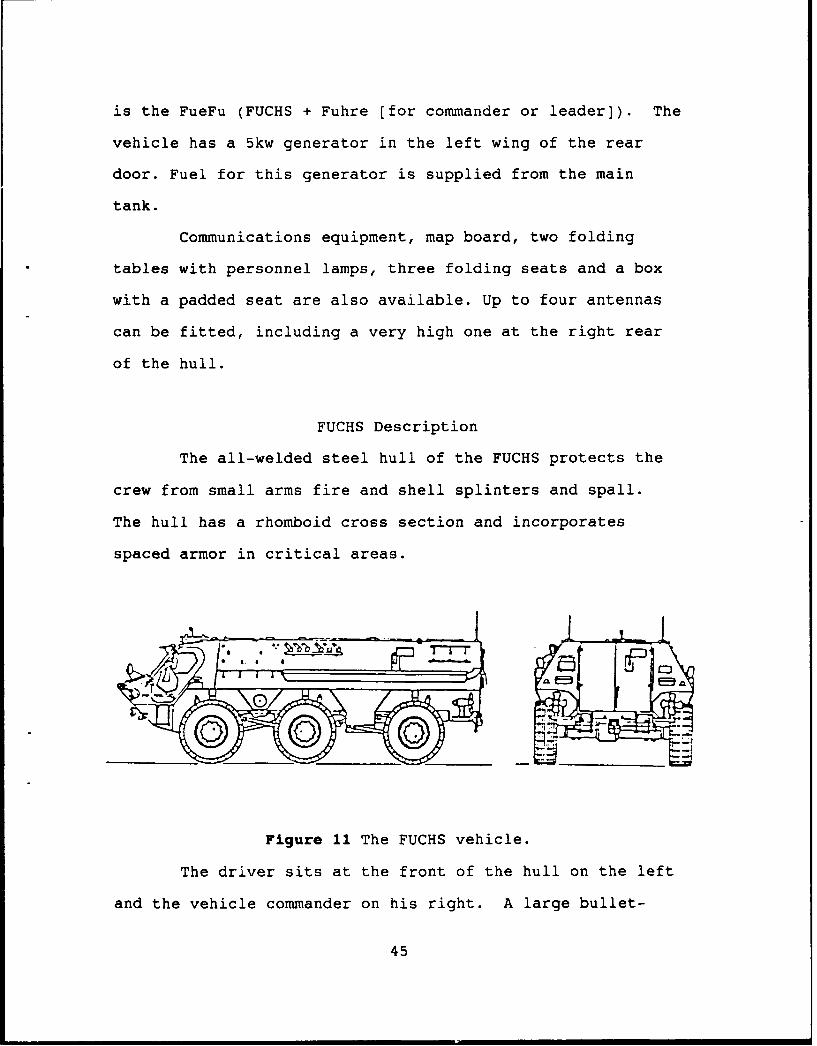
is the FueFu (FUCHS + Fuhre (for commander or leader]). The
vehicle has a 5kw generator in the left wing of the rear
door. Fuel for this generator is supplied from the main
tank.
Communications equipment, map board, two folding
tables with personnel lamps, three folding seats and a box
with a padded seat are also available. Up to four antennas
can be fitted, including a very high one at the right rear
of the hull.
FUCHS Description
The all-welded steel hull of the FUCHS protects the
crew from small arms fire and shell splinters and spall.
The hull has a rhomboid cross section and incorporates
spaced armor in critical areas.
Figure 11 The FUCHS vehicle.
The driver sits at the front of the hull on the left
and the vehicle commander on his right. A large bullet-
45

proof windscreen to their front can be covered by an armored
shutter hinged at the top. There are four periscopes fitted
to the drivers roof hatch and the center one can be replaced
by a passive periscope for nigh+ operations.
FUCHS INTERIOR ARRANGEMENT
Engine/transmissionOn-board Aux Generator Compartment Driver's Position
Map Board
Crew CompartmentWorking Area
Vehicle Commander'sPosition
NBC OVER-PRESSURE SYSTEM
Figure 12 This diagram presents an over-head view of theFUCHS vehicle. The driver and commander are situated forward.
The engine compartment is located behind the driver
and contains an eight-cylinder Mercedes-Benz OM 402A exhaust
turbo-charged, liquid cooled, diesel developing 320 hp at
2500 rpm. The transmission is a ZF model HP 500 6-speed
automatic.
The transporter is fully amphibious being propelled
46

by two four-blade propellers beneath the floor level of the
vehicle at the rear of the hull. The propellers can be
traversed through 360 degrees to provide steering. Nominal
amphibious payload is 4410 pounds.
The vehicle has a NBC over-pressure system, which can
ventilate both the crew and personnel compartments. One
export variant of this vehicle does have the ability to air
condition the crew and driver compartment. The vehicle can
mount a 7.62 over the commanders hatch ring or a 2?mm
Rheinmetall cannon over the first circular roof hatch of the
crew compartment.9
The cargo compartment has up to 19.6 square feet.
protection system, heaters, batteries and radio equipment
are fitted on top of the wheel housing to save space.
9Jane's Armour and Artillery, 1988-89, Jane's Information
Group, New York, 1988, p 296-298.
47

Comparison of the Four Variants
The definitions of the five criteria used for
analysis of the variants are important to understand. The
definitions as they are used in this study are presented in
the following paragraphs. In completing this study efforts
were made to ensure the material presented was clear,
concise and unclassified. Some of the criteria lend
themselves to easy complication by continually adding on
sub-criteria and related data. In this study each of the
five main criteria are divided into no more than four sub-
criteria.
In using the decision matrixes, it was decided
initially that higher numbers would be better for the
scoring process. Each of the vehicles performance data for
each criteria was entered into the matrix and a score
assigned based on comparison. A "one" is the lowest score
possible in each category and a "four" is the highest. In
the event that two vehicles had the same performance data in
any given category, they were both assigned the same score
in descending order with the other variants.
Mobility
The first area of comparison is mobility. This
criteria is made up of four sub-criteria. The sub-criteria
are: range, maximum speed capability, maximum water fording
48
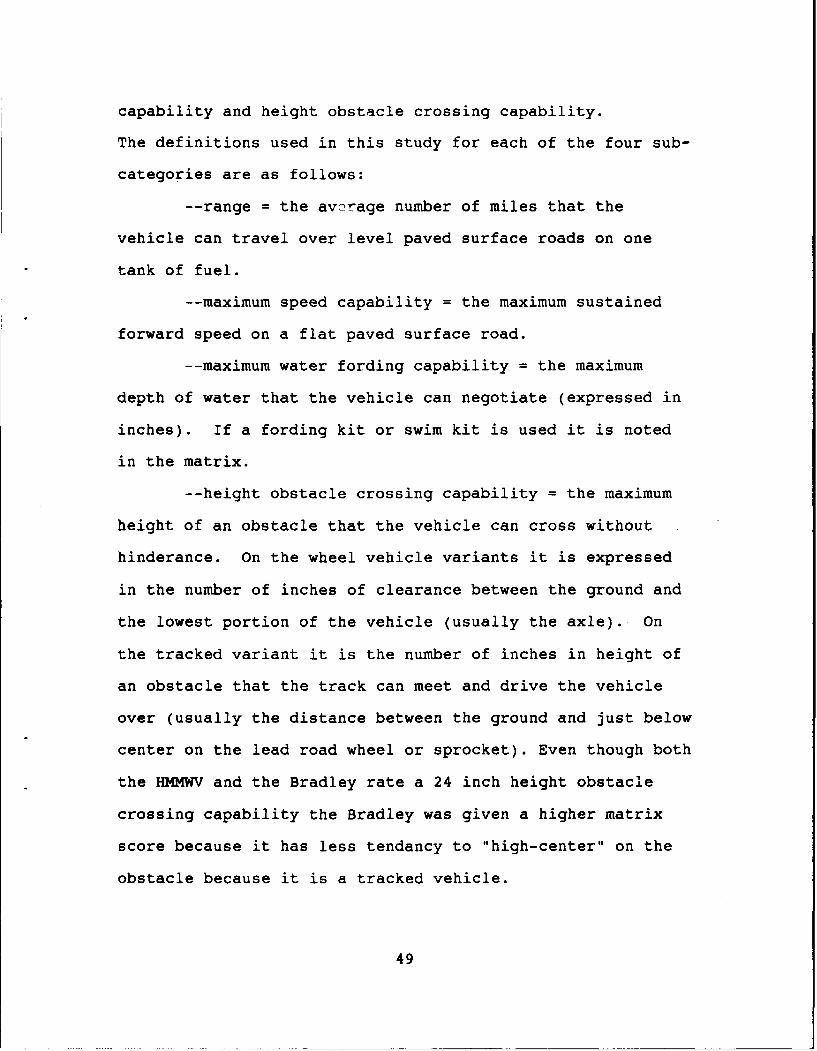
capability and height obstacle crossing capability.
The definitions used in this study for each of the four sub-
categories are as follows:
-- range = the average number of miles that the
vehicle can travel over level paved surface roads on one
tank of fuel.
-- maximum speed capability = the maximum sustained
forward speed on a flat paved surface road.
-- maximum water fording capability = the maximum
depth of water that the vehicle can negotiate (expressed in
inches). If a fording kit or swim kit is used it is noted
in the matrix.
-- height obstacle crossing capability = the maximum
height of an obstacle that the vehicle can cross without
hinderance. On the wheel vehicle variants it is expressed
in the number of inches of clearance between the ground and
the lowest portion of the vehicle (usually the axle). On
the tracked variant it is the number of inches in height of
an obstacle that the track can meet and drive the vehicle
over (usually the distance between the ground and just below
center on the lead road wheel or sprocket). Even though both
the HMMWV and the Bradley rate a 24 inch height obstacle
crossing capability the Bradley was given a higher matrix
score because it has less tendancy to "high-center" on the
obstacle because it is a tracked vehicle.
49

The application of the given data yields the results given
in Figure 13 below.
MOBILITY MATRIXHIGHER 18 BETTERA. O
SCOCOR
S9HMMo ,,2,/2 /2/
4
VARIANT 31 3o 57 s a11FUCHS 21 24 V
VARIANT 4 /90 65 REP
MILES MPH INCHES INCHES
Figure 13 The FUCHS and Bradley are rated as best inmobility. Objectively speaking, the FUCHS rates best overall
because of it's faster speed and swim capability.
50
Survivability
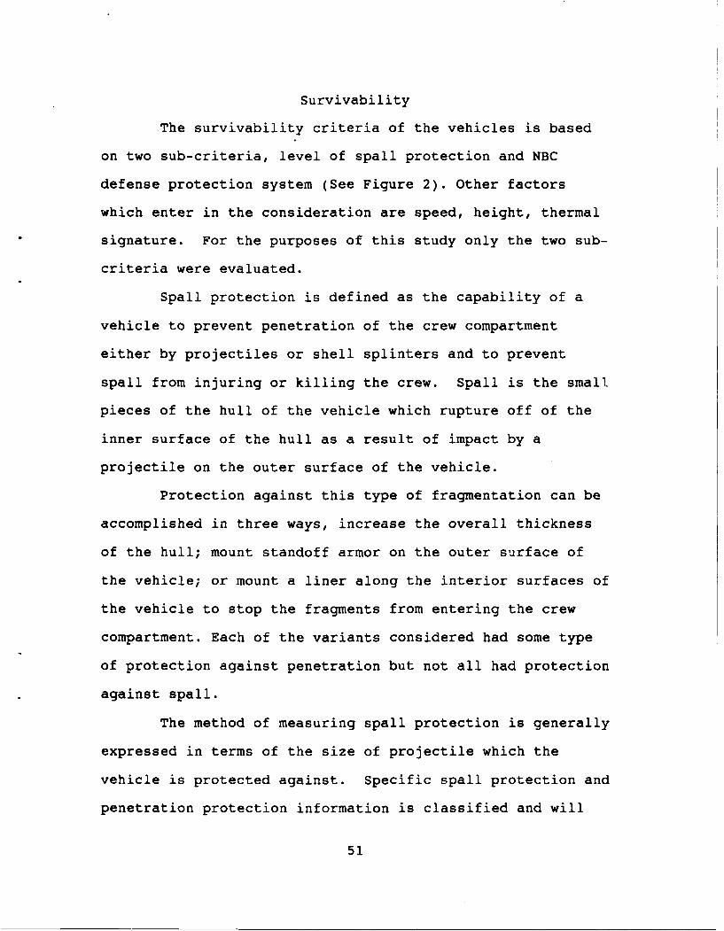
The survivability criteria of the vehicles is based
on two sub-criteria, level of spall protection and NBC
defense protection system (See Figure 2). Other factors
which enter in the consideration are speed, height, thermal
signature. For the purposes of this study only the two sub-
criteria were evaluated.
Spall protection is defined as the capability of a
vehicle to prevent penetration of the crew compartment
either by projectiles or shell splinters and to prevent
spall from injuring or killing the crew. Spall is the small
pieces of the hull of the vehicle which rupture off of the
inner surface of the hull as a result of impact by a
projectile on the outer surface of the vehicle.
Protection against this type of fragmentation can be
accomplished in three ways, increase the overall thickness
of the hull; mount standoff armor on the outer surface of
the vehicle; or mount a liner along the interior surfaces of
the vehicle to stop the fragments from entering the crew
compartment. Each of the variants considered had some type
of protection against penetration but not all had protection
against spall.
The method of measuring spall protection is generally
expressed in terms of the size of projectile which the
vehicle is protected against. Specific spall protection and
penetration protection information is classified and will
51
not be included in the data considered for this study.
NBC over-pressure is a system which provides a
positive air pressure in the interior portion of the
vehicle. This air pressure is maintained by pumping outside
air through a decontamination system and into the crew
compartment. The crew does not have to wear gas masks for
this system to be effective.
Older vehicle NBC systems include a gas-particulate
system which is an air pump which forces air through a set
of large filters mounted in the vehicle. The crewmen must
wear their masks and connect a hose from their mask to the
gas particulate system which provides them with clean
decontaminated air.
The gas particulate system was not considered an
over-pressure system in this study. Crew proficiency is
degraded by having to operate while wearing gas masks,
especially when hooked-up to this type of system by a hose.
52

SURVIVABILITY MATRIXHISHE1 I' 3ETTER * +#
0ML q SCORE
HMMWV 1 3 4 PLAC
VARIANT GAS 'RTICULEVT1 NONE /NO SYSTEM ONLY
(FULL CREW)
HEMTT 2 2 4/N OVER-PRESSURE IN
VARIANT 2 EVLOP- YES ,,CP SHELTER ONLYMEN? NOT FOR TC/DVR
BRADLEY 4 15P TC 3 PLACEVARIANT 3 12.7 MM NO GAO IARTICULATE
SYSTEM ONLY
FUCHS 3 47VARIANT 4 YES
Figure 14 The Bradley does have the capability to add-onadditional armor which may make it superior in overallsurvivability. Adding on armor severly limits mobility anddeployability.
53

Compatability/Cost
The compatibility and cost of each vehicle were
treated as two criteria within the same matrix.
Compatibility is defined as the capability of the vehicle to
assume the command and control role without modification.
The base cost of the vehicle is the approximate purchase
cost of the vehicle in 1990 dollars.
COMPATABILITY COST oHIGHER 18 BETTER #
4% SCOREHMMWV /3 .4s 35 7
VARIANT 1 MINOR MOD REO
HEMTT 4NO 7VA2cP .not fullyVARIANT 2 No /160K+/- testd or fielded
BRADLEY 3/ 4VARIANT 3 YES 1.5M MINOR MOD REQ
FUCHS No/2tNot fielded In
V4US ArmyVARIANTNO 900K C2 configuration
Figure 15 Even though the HEMTT/SICPS and the FUCHS both havespecific C2 designs, the HEMTT scores better than the FUCHS inrequired modifications because it is already partiallyfielded.
54

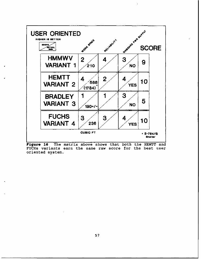
User Oriented
An important consideration in studying a command and
control vehicle is whether or not the vehicle is "user
friendly". This criteria was made up initially of three
sub-criteria; cubic feet of work space, reliability, and
whether or not the vehicle has an on-board power supply
which can handle the expected power requirements without the
operation of the main engine.
Reliability can still be regarded as questionable
because I was not able to obtain the information on mean
time between failures for the FUCHS variant. The numbers
ranking on the matrix (see User Oriented Matrix) are simply
my ranking of the vehicles based on my personal experience.
My rationale for the ranking is as follows. The
HMMWV ranked as best overall because it represented a well
tested vehicle which operated well and is not very
complicated. The FUCHS as second best because of the
reputation of German vehicles as being "the best Deutsche
Marks can buy". In in the author's Desert Shield, Desert
Storm experience, I never witnessed a FUCHS (NBCRS) FOX
Recon vehicle go down for maintenance during an 8 month tour
in Saudi Arabia. The HEMTT rated next to last due to the
size and complexity of the vehicle and the unknown
reliability characteristics of the Standardized Integrated
Command Post (SICPs) unit. Finally, the Bradley ranked last
55

due to the fact that it is a tracked vehicle with
maintenance that has historically been high on tracked
vehicles.
The work space figures represent the cubic footage
available in each of the variants. No clear dimensions were
available for the Bradley, but using the author's
experience, it is easily the smallest of the four on cubic
footage available and thus rates a "one".
The on-board power supply is a feature near and dear
to anyone who has ever had to wrestle with the 4.2kw
generator or a towed 5-30kw trailer as part of the command
post. This feature allows for greater mobility and ease of
operation.
56
USER ORIENTEDMIGHEM 18 BETTERA
'O.K -q"*SCORESoo/ / 9cRVARIANT 1 21•0 NO
VARIANT 2 588 10//1784)
BRADLEY 1 3VARIANT 3 5
FUCHS 3/ 3• 4/y 10
VARIANT 4 236
CUBIC FT - 8-784/GSheltor
Figure 16 The matrix above shows that both the HEMTT andFUCHs variants earn the same raw score for the best useroriented system.
57
Deployability
The final criteria to discuss is the area of
deployability. For this criteria there are only two sub-
criteria. They are overall vehicle height and the weight of
the vehicle when combat loaded. This data was readily
available in a number of sources. (See Figure 17).
The Bradley has a "reducible" height as discussed in
the description. (See p 43). The HEMTT and SICPs shelter
combination is the tallest and the heaviest. The height
could be reduced by dismounting the shelter from the cargo
bed.
58
DEPLOYABILITY MATRIXHIGHER 18 BETTER
400
L~A ie SCOREHMMWV 4/ 3 4 11
VARIANT 1 10,5K o100 IN NOPREP
HEMTT / 1 3 5VARIANT 2 66.9K 147 IN I N 2ODE HEUMT* 6N2 ATS SHELTER - 3,9K
BRADLEY 2 2 /2/ 6VARIANT 3 44K 102 IN .A.LRET/ /CRE (SEE TEXT)
FUCHS .3/ 4 4 11VARIANT 4/ 38,4 K 90-' IN RQI
Figure 17 Naturally the smaller and lighter vehicles wouldscore better in the area of deployability. The FUCHs scoredvery well for an armored vehicle.
59
CHAPTER 5
RECOMMENDATION AND CONCLUSION
The compiled scores from each of the matrixes rere
incorporated into a final matrix to determine the Dest
vehicle. In order to determine weighting of the criteria in
the final decision matrix a survey was used as discussed in
Chapter 3. The results of this survey are as depicted in
figure 1.
The weighting of these criteria determine the final
decision. The raw scores indicate that the best choice is the
FUCHS variant as it received the highest scores 1. the
mobility criteria and tied scores for the best in the
transportability and survivability criteria.
After applying the data from the surveys (See Figure
1), the final scores place the FUCHS variant as the best
choice. This is based primarily on the fact that the FUCHS
scored the best in deployability and mobility which are the
two most important factors according to the survey data. With
the weighting factor applied, the FUCHS continues to rank the
60

RANK ORDER/WEIGHTING OF CRITERIATOTAL NUMBER POLLED - 75 TOTAL NUMBER RESPONDING - 42
TOTAL SURVEYS COMPLETE AND USABLE @ 37
Relative
CRITERIA Weight
DEPLOYABILITY 37% MOST IMPORTANT 1.0
MOBILITY 27% .8
USER ORIENTED 27% .6
SURVIVABILITY 37% .4
COMPATABILITY 65% LEAST IMPORTANT .2
65% OF THE RESPONDENTS HAD EXPERIENCE WITH THE M677 SERIES
Figure 1 The percentages show how respondents placed each ofthe criteria in importance, i.e. 37% agreed deployabilityshould be ranked as most important, 27% agreed that mobilityshould be second, etc. Weighting is in 1/5 increments.
best, and the margin between the FUCHS and the HMMWV was
expanded (See Figure 2). Although the FUCHS scored high in
other areas it's biggest prcb.em area is the fact that it
isn't currently fielded in the command and control variant in
the U.S. Army.
After reviewing the data, my subjective judgement and
military experience also tells me that the FUCHS is the best
vehicle, for the type of mission profile that the Light
61

BEST VARIANT MATRIXHIGHER IS BETTER
WEIGHT FATOR .4 .6 .8 ,0.2 Q4.o SCORE
HMMWV 4 9 9/ 7/ 11 40/
VARIANT 1 / I/1.6 5.4 7.2 1.4 11.0/ 26.6
/
HEMTT 4 10 9 7 5 365//
VARIANT 2 Y1.6 /6.0 7.2 X1.4 X5.0 /21.2
BRADLEY 6 5 /11 4 6 31VARIANT 3
/
VARIANT 3 2 8 6 /0 20.6
FUCHS 7 10 13 5/ 11 / 46 ,
VARIANT 4 2.8.0 . 31.2
Figure 2 Final decision matrix showing raw score totals andscores that each variant received after "weighting" each ofthe critieria.
Cavalry Regiment will face. It's mobility and on-board
capabilites make it more suitable for the variety of
conditions and terrain that the LCR may have to operate in.
The author does not agree with the outcome of the
survey which weighted the selection criteria as shown in
Figure 1. I believe the vehicle has to get where it is going
first and then survive after it arrives. Survivability has to
be the next important factor after deployability.
62

Conclusion
The world as we knew it for the past 40 years is
changing rapidly. The Army must .na-"e just as rapidly in
order to provide security for our national interests. At the
same time the Army must look for ways to modernize its force
while enduring a decreased operating budget.
American forces now can find themselves deployed, on
very short notice, anywhere in the world. Light Cavalry as an
adjunct to either a CONUS (continental United States) based
contingency corps (currently XVIII Corps) or to a forward
deployed corps in Europe will soon be a reality.
This study has attempted to identify a vehicle already
in the Army inventory, that might be a better solution than
the M577 series for a command and control vehicle for the
Light Cavalry Regiment. The concept for the employment of the
C2 vehicle, and what it may be required to do, varies.
Future CPs will operate dispersed in order to enhance
survivability since the CP must survive first, in order to
function. Today, dispersion doctrinally thought of as 3-15
kilometers in distance separating the various cells of the
CP.I Dispersion in the future may be in hundreds of
kilometers, with only the operations and current battle cell
deployed forward and the plans and future battle cell
'Continqency Force Operations, C4000-11, Section IX,Dispersed Command Posts, U.S. Army Command and General StaffCollege, Apr 91, p 11-1-40.
63
remaining at home station.
When considering the variants discussed in this study
it is easy to quickly get into an "apples and oranges"
discussion because some of the variants could be considered
more of a fighting vehicle and as such, a good platform for
the commander to use in moving around the battlefield. Other
variants provide good mobility and a large work area but less
protection or self defense capability. Therefore, they would
be considered more of a mobile communications center rather
than a fighting command and control platform for the commander
to use. But, if the future holds that the mission of the LCR
is to initially secure the lodgement, and next go 100-200
kilometers out and secure the expanse of area required for a
corps deployment, then a communications platform is the
desired naracteristic rather than a "fighting/self defending"
vehicle.
The FUCHS command and control vehicle meets the
requirement for the future in providing the type of vehicle
the U.S. Army needs. However, purchase price may be such a
detractor that the FUCHS as a C2 vehicle may never become a
reality in the U.S. Army.
Without a doubt, the current M577 command and control
vehicle is unsatisfactory. The FUCHs best meets the
requirements for a new command and control vehicle which will
be able to keep pace with a fast and agile light cavalry
64
regiment. The FUCHs will provide the commander with a
platform capable of deploying quickly and surviving on the
battlefields of the future.
65
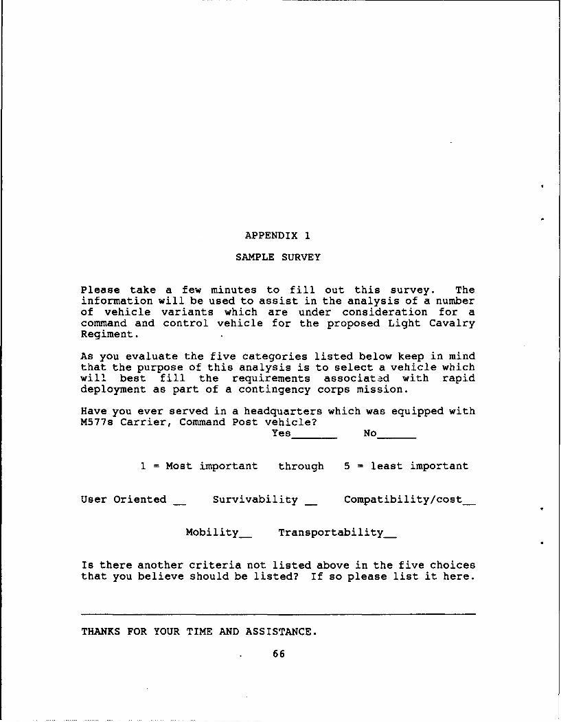
APPENDIX 1
SAMPLE SURVEY
Please take a few minutes to fill out this survey. Theinformation will be used to assist in the analysis of a numberof vehicle variants which are under consideration for acommand and control vehicle for the proposed Light CavalryRegiment.
As you evaluate the five categories listed below keep in mindthat the purpose of this analysis is to select a vehicle whichwill best fill the requirements associated with rapiddeployment as part of a contingency corps mission.
Have you ever served in a headquarters which was equipped withM577s Carrier, Command Post vehicle?
Yes No
1 = Most important through 5 = least important
User Oriented Survivability__ Compatibility/cost_
Mobility_ Transportability_
Is there another criteria not listed above in the five choicesthat you believe should be listed? If so please list it here.
THANKS FOR YOUR TIME AND ASSISTANCE.
66

APPENDIX 2
THE LAV-25
During the time that this study was produced the basic
Light Cavalry Regiment (LCR) organization as discussed in
Chapter 1 (Figure 3) has still not received final approval.
Additional versions have been proposed to the base
organization. One of the versions under consideration is
based on the General Motors Corporation, LAV-25. The LAV-25
is currently in use with by the U.S. Marine Corps.
" " "..• 7. -- " /..7 -'
\\ •z;•- i,.•, •'.. -. ,
\\ ', .;, - .,-•%, .' .I )f<.,
7 7
THE GENERAL MOTORS 8x8 COMMAND AND CONTROL VEHICLE
67
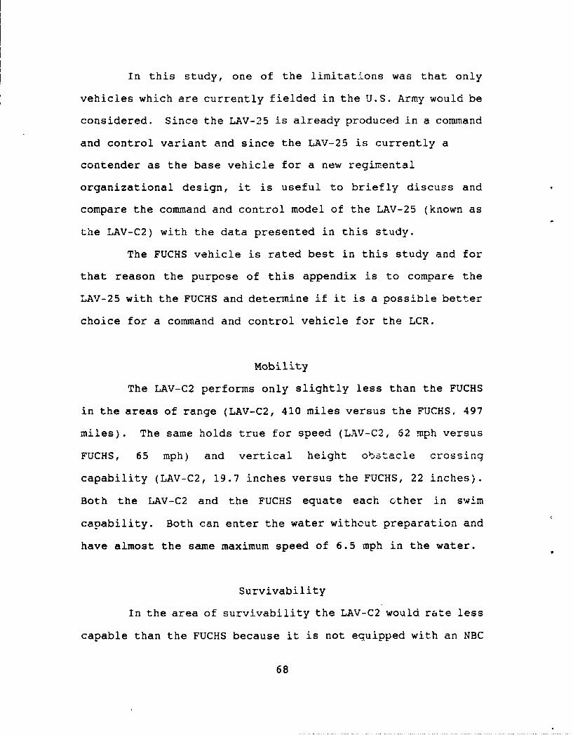
In this study, one of the limitations was that only
vehicles which are currently fielded in the U.S. Army would be
considered. Since the LAV-25 is already produced in a command
and control variant and since the LAV-25 is currently a
contender as the base vehicle for a new regimental
organizational design, it is useful to briefly discuss and
compare the command and control model of the LAV-25 (known as
the LAV-C2) with the data presented in this study.
The FUCHS vehicle is rated best in this study and for
that reason the purpose of this appendix is to compare the
LAV-25 with the FUCHS and determine if it is a possible better
choice for a command and control vehicle for the LCR.
Mobility
The LAV-C2 performs only slightly less than the FUCHS
in the areas of range (LAV-C2, 410 miles versus the FUCHS, 497
miles). The same holds true for speed (LAV-C2, 62 mph versus
FUCHS, 65 mph) and vertical height obstacle crossing
capability (LAV-C2, 19.7 inches versus the FUCHS, 22 inches).
Both the LAV-C2 and the FUCHS equate each other in swim
capability. Both can enter the water without preparation and
have almost the same maximum speed of 6.5 mph in the water.
Survivability
In the area of survivability the LAV-C2 would rate less
capable than the FUCHS because it is not equipped with an NBC
68
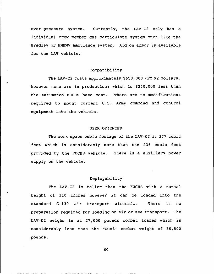
over-pressure system. Currently, the LAV-C2 only has a
individual crew member gas particulate system much like the
Bradley or HMMWV Ambulance system. Add on armor is available
for the LAV vehicle.
Compatibility
The LAV-C2 costs approximately $650,000 (FY 92 dollars,
however none are in production) which is $250,000 less than
the estimated FUCHS base cost. There are no modifications
required to mount current U.S. Army command and control
equipment into the vehicle.
USER ORIENTED
The work space cubic footage of the LAV-C2 is 377 cubic
feet which is considerably more than the 236 cubic feet
provided by the FUCHS vehicle. There is a auxiliary power
supply on the vehicle.
Deployability
The LAV-C2 is taller than the FUCHS with a normal
height of 110 inches however it can be loaded into the
standard C-130 air transport aircraft. There is no
preparation required for loading on air or sea transport. The
LAV-C2 weighs in at 27,000 pounds combat loaded which is
considerably less than the FUCHS' combat weight of 36,800
pounds.
69

Since the LAV-C2 is a close contender to the
capabilities of the FUCHS vehicle the LAV-C2 should be given
strong consideration as a command and control variant. If the
base vehicle of the regiment is the LAV-25 vehicle, the
benefits of using the same power train and base vehicle might
outweigh those gained by using a totally different vehicle
even if that vehicle is slightly superior in some
capabilities.
70
BIBLIOGRAPHY
Andriole, Stephen J. High Technology Inititives in C31.Washington, D.C.: AFCEA International Press, c1986.
Armor 2000 - Armor on the Future Battlefield. US Army ArmorCenter and Fort Knox, May 91.
Beam, Walter R. Command, Control and Communications SystemsEngineering. New York: McGraw Hill, c1989.
Blair, Clay. Ridways Paratroopers: The American Airborne inWWII. Garden City, New York, Dial Press, 1985.
Cavalry Operations on the Airland Operations Battlefield.US Army Armor Center and Fort Knox, May 90
Chief of Staff, US Army, White Paper, 1984, Light InfantryDivisions. Headquarters, Dept of the Army, Washington,D.C., May 1984.
Command and Control in North African Battles, World War II,1941-1943. Ben-Reuven E. Army War College, CarlisleBarracks, Pa., 19 May 89.
Contingency Force Operations. C4000-11, Section IX, DispersedCommand Posts, U.S. Army Command and General StaffCollege, Apr 91.
Cushman, John H. Command and Control of Theater Forces.Cambridge, Mass: Harvard University, 1983.
Desert Storm Archives MaterialPartial Title DSSSP Catalogue #
1-4 CAV Narrative History DSTA1Brigade Command and Control DSTA44C2 DSOP41C2 over tasked vehicle assets DSSN13
71

Command and Control in a heavy Bde-mvmt DSTA44Command and Control Observations DSTA43Interview with Col Frank Akers, G-3 XVIII DSST12Performance of Equipment in extreme condi DSSN12
FM 100-5, Operations. Headquarters, Department of the Army,Washington D.C. May 1984.
FM-101-5-1, Operational Terms and Symbols. Headquarters,Department of the Army, Washington, D.C., Oct 1985.
FMC Factsheet, The XM577A3, Armored Tactical Command andControl System. FMC Corporation, Ground SystemsDivision, Santa Clara, California, May 1991.
Foley, Thomas C. Armor 2000 - A Balanced Force for the Armyof The Future. US Army Armor Center and Fort Knox, Jul90.
Fox, David J. The Research Process in Education. Holt,Rinehart and Winstrn, Inc., New York, 1976.
Goedkoop, T.R. Task Force Tactical Operations Center: AnOrganization for Success. U.S. Army Command and GeneralStaff College, School of Advanced Military Studies,Monograph, Ft Leavenworth, Kansas, 27 Nov 1988.
Jane's C31 Systems. Jane's Information Group, New York, 1987.
Jane's Military Logistics. Jane's Information Group, NewYork, 1989.
Jane's Military Vehicles and Ground Support Equipment. 1985.Janes Publishing Inc., New York, 1985.
Jane's Armour and Artillery, 1988-89. Jane's InformationGroup, New York, 1988.
Johnson, Stuart E. Science of Command and Control.Washington D.C.: AFCEA International Press, c1989.
Lane, John J. Command and Control and Communications.Maxwell Airforce Base, Ala., Air University, Air WarCollege, 1986.
Long, Dennis H. United States Army Armor Center DesertShield/Storm Emerging Observations. Directorate of TotalArmor Force Readiness, US Army Armor Center and FortKnox, 24 July 91.
72
Matthews, George F. Initial Transportability EngineeringAnalysis of the Nuclear-Biological-chemicalReconnaissance System (NBCRS) FUCHS TPZ1 Version.Military Traffic Management Command, Nov 1986.
McElwee, J.W. First Cut at Doctrine for Automation ofPivision Command and Control. U.S. Army Command andGeneral Staff College, School of Advanced MilitaryStudies,Thesis Paper, Fort Leavenworth, Kansas, 2 Dec1985.
Mobile Command Post Vehicles. CDOG Project Nr USACGSC 57-4,15 July 1958. Fort Leavenworth Archives #N-18378.128B
Northwood, Arthur. Rendezvous with Destiny- A History of the101st Airborne Division. Greenville, Tx., 101stAirborne Division Association, 1965.
Public Affairs Fact Sheet, Subject: Army Standards Family ofRigid Wall Tactical Shelters, S-280/G Shelter. U.S.Army Natick Research, Development and EngineeringCenter, Nov 91.
Public Affairs Fact Sheet, Subject: Army Standards Family ofRigid Wall Tactical ISO Shelters. U.S. NatickResearch, Development and Engineering Center, Nov 91.
Rice, M. A. Communications and Information Systems ForBattlefield Command and Control. London, Washington,Brassey's Publishing, 1989.
Rockwell, James M. Tactical C3 for the Ground Forces.Washington, D.C.: AFCEA International Press, c1986.
Sajo, J. R. Command Post: A Comparison of Tactical CommandPost Doctrine of the U.S. And Soviet Armies. U.S. ArmyCommand and General Staff Jollege, Masters Thesis, Mar1988.
Swan, G. C. Tactical Reconnaissance fore the Heavy BrigadeCommander: How Much is Not Enough. U.S. Army Command andGeneral Staff College, School of Advanced MilitaryStudies, Monograph, Fort Leavenworth, Kansas, 14 Dec 88.
TM 9-2320-280-10, Change 2, Ambulance, 4-Litter, Armored M997.Oct 1987.
Van Creveld, Martin L. Command in War. Cambridge,Massachusetts: Harvard University Press, 1985.
Ware, H. L. Command Presence: Where Should the OperationalCommander Be Located On the Modern Battlefield.
73

U.S. Army Command and General Staff College, MastersThesis, Fort Leavenworth, Kansas, 14 May 1989.
Weisband, S. P., J. M. Linville, M. J. Liebhaber, R. W.Obermayer, and J. J. Fallesen. Computer-Mediated GroupProcesses in Distributed Command and Control Systems.Vreuls Research Corp., Thousandý Oaks, Calif., Jun 1988.
Willcox, A.M. Command, Control & Communications. Oxford; NewYork: Brassey's Defense Publishers, C1983.
74

INITIAL DISTRIBUTION LIST
1. Combined Arms Research LibraryU.S. Army Command and General Staff CollegeFort Leavenworth, Kansas 66027-6900
2. Colonel Robert HurleyDirector, Aviation Requirements forCombat Structure of the Army (ARCSA V),Special Study GroupFort Leavenworth, Kansas 66027
3. Defense Technical Information CenterCameron StationAlexandria, Virginia 22314
4. Directorate for Total Armor Force ReadinessU.S. Army Armor Center and Fort KnoxFort Knox, Kentucky 40121
5. Dr. Lon R. SeglieCenter For Army Lessons LearnedCombined Arms CenterFort Leavenworth, Kansas 66027
6. LTC Jon MoilanenCenter for Army TacticsU.S. Army Command and General Staff CollegeFort Leavenworth, Kansas 66027
6. U.S. Army Armor Center and Fort KnoxArmor Center LibraryFort Knox, Kentucky 40121
75