a combined approach for head motion stabilization using...
TRANSCRIPT
University of Minho Department of Industrial Electronics Electronic
Master thesis report2007/2008
A combined Approach for HeadMotion Stabilization using CentralPatterns Generators and a Genetic
Algorithm
Miguel Alexandre Campos Oliveira
Guimaraes, 2008
– i –

University of MinhoDepartment of Industrial Electronics Electronic
Master thesis reportMaster Degree on Industrial Electronics and ComputersYear 2007/08
A combined Approach for HeadMotion Stabilization using CentralPatterns Generators and a Genetic
Algorithm
Miguel Alexandre Campos Oliveira nº 29281
Under supervision of:Cristina Manuela Peixoto Santos, Auxiliar Professor at the Industrial Electronics
Department, University of Minho
Guimaraes, 2008
– ii –

”There are five steps to reach the wisdom: to be silent, to hear, to remember, to act andto study”
Arab saying
To my friends
– iii –

My thanks toI would like to thanks to the following people:
- Professor Cristina Manuela Peixoto Santos, for the incentive, knowledge and supportduring the thesis work and in these last years, working together.
- Professor Manuel Joao Oliveira Ferreira, for his untiring energy that never ends.
- To all my colleges that work with me on the ASBG group during these last years:Victor Emanuel da Silva MendesJose Afonso Machado PiresPatricia Corral RicaldeLuiz Castro
- A special thanks to Professors Ana Maria Alves Coutinho Rocha and Lino AntonioAntunes Fernandes Costa for their help and knowledge on optimization systems.
– iv –

AbstractIn this master thesis, we focus on the development of a quadruped locomotion con-
troller able to stabilize the robot head during the robot movement. The controller ar-chitecture is bio-inspired on motor pattern generators (MPGs). It is based on non-lineardynamical system, that generate rhythmic and discrete trajectories.
The head shaking that results from robot locomotion is important because it difficultsstable image acquisition and the possibility to rely on that information to act accordingly,for instance, to achieve visually-guided locomotion.
We focus on the development of a head controller able to minimize the head motioninduced by locomotion itself. Specifically, we propose a combined approach to generatehead movement stabilization on a quadruped robot, using Motor Pattern Generators(MPGs) and a genetic algorithm.
Head movement is generated by MPGs which are modelled as autonomous differen-tial equations. Specifically, we couple Hopf oscillators. This approach allows to explicitlyspecify parameters such as amplitude, offset and frequency of movement and to smoothlymodulate the generated trajectories according to changes in these parameters. It is there-fore easy to combine the MPG with an optimization method. A genetic algorithm de-termines the best set of parameters that generates the head movement that reduces thehead shaking caused by locomotion.
Experimental results on a simulated AIBO robot demonstrate that the proposedapproach generates head movement that reduces the one induced by locomotion.
– v –

ResumoNesta tese de mestrado, e desenvolvido um controlador para locomocao de um robo
quadruped (Aibo), capaz de estabilizar a cabeca do robo durante o movimento deste.A arquitectura de controlo e inspirada no conceito biologico dos motor pattern gen-
erator (MPG) e e baseada em sistemas dinamicos nao lineares que geram trajectoriasrıtmicas e discretas.
A oscilacao da cabeca que resulta da locomocao do robo e importante porque dificultauma estavel aquisicao de imagens e a possibilidade de o robot actuar de acordo com ainformacao recebida. Por exemplo, locomocao orientada pela visao.
Focamo-nos no desenvolvimento de um controlador para a cabeca do robo, capaz deminimizar a oscilacao da cabeca induzida pela locomocao. E proposta uma solucao quecombina MPG e algoritmos geneticos para gerar Um movimento da cabeca estavel.
O movimento de estabilizacao da cabeca e gerado por MPGs que sao modeladoscomo equacoes diferenciais. Esta solucao permite especificar parametros com a ampli-tude, o offset e a frequencia do movimento e gerar trajectorias suaves de acordo com asalteracoes dos parametros. Assim torna-se mais facil combinar os MPGs com um metodode optimizacao. O algoritmo genetico determina o melhor conjunto de parametros quegera o movimento da cabeca que reduz a oscilacao da cabeca induzida pela locomocao.
Resultados experimentais num robo Aibo simulado, demonstram que a solucao pro-posta gera um movimento da cabeca que reduz o movimento induzido pela locomocao.
– vi –

Contents
1 Introduction 11.1 Objectives . . . . . . . . . . . . . . . . . . . . . . . . . . . . . . . . . . . . 41.2 Motivation . . . . . . . . . . . . . . . . . . . . . . . . . . . . . . . . . . . . 51.3 Research Method . . . . . . . . . . . . . . . . . . . . . . . . . . . . . . . . 51.4 Report Structure . . . . . . . . . . . . . . . . . . . . . . . . . . . . . . . . 6
2 State of the Art 82.1 Nonlinear dynamical system for movement generation . . . . . . . . . . . . 82.2 Head Stabilization . . . . . . . . . . . . . . . . . . . . . . . . . . . . . . . 10
3 Tools 113.1 Aibo ERS-7 . . . . . . . . . . . . . . . . . . . . . . . . . . . . . . . . . . . 113.2 Webots . . . . . . . . . . . . . . . . . . . . . . . . . . . . . . . . . . . . . . 12
4 Motor Pattern Generator (MPG) 144.0.1 Intrinsic properties of the MPG . . . . . . . . . . . . . . . . . . . . 16
5 Locomotion Generation 185.1 Overall Architecture . . . . . . . . . . . . . . . . . . . . . . . . . . . . . . 18
5.1.1 Robotic Setup . . . . . . . . . . . . . . . . . . . . . . . . . . . . . . 195.1.2 Controller Architecture . . . . . . . . . . . . . . . . . . . . . . . . . 20
5.2 Locomotion Pattern . . . . . . . . . . . . . . . . . . . . . . . . . . . . . . . 215.3 Simulations . . . . . . . . . . . . . . . . . . . . . . . . . . . . . . . . . . . 21
6 Head Motion Stabilization 256.1 System Architecture . . . . . . . . . . . . . . . . . . . . . . . . . . . . . . 256.2 Head Movement Generation . . . . . . . . . . . . . . . . . . . . . . . . . . 26
6.2.1 Analysis of the Head Movement . . . . . . . . . . . . . . . . . . . . 27
7 Optimization System 307.1 Genetic Algorithm . . . . . . . . . . . . . . . . . . . . . . . . . . . . . . . 317.2 Fitness Evaluation . . . . . . . . . . . . . . . . . . . . . . . . . . . . . . . 337.3 Results . . . . . . . . . . . . . . . . . . . . . . . . . . . . . . . . . . . . . . 34
– vii –
8 Simulation Results 38
9 Conclusion 40
Bibliography 44
Appendix 45
A Kinematics 45
B ERS-7 Aibo Specifications 47
– viii –
table of tables
5.1 Aibo DOF’s specification . . . . . . . . . . . . . . . . . . . . . . . . . . . . 195.2 Phase differences for walking gait . . . . . . . . . . . . . . . . . . . . . . . 215.3 Walking gait MPG parameters for hip joints . . . . . . . . . . . . . . . . . 225.4 Walking gait MPG parameters for knee joints . . . . . . . . . . . . . . . . 22
7.1 Search ranges of MPG parameters . . . . . . . . . . . . . . . . . . . . . . . 337.2 Search ranges of MPG parameters . . . . . . . . . . . . . . . . . . . . . . . 357.3 maximal movement variation in the (X, Y, Z) . . . . . . . . . . . . . . . . 36
8.1 Parameter values for generating head motion . . . . . . . . . . . . . . . . . 38
– ix –
table of figures
3.1 ERS-7 Aibo robot . . . . . . . . . . . . . . . . . . . . . . . . . . . . . . . . 113.2 Joints of the Aibo neck . . . . . . . . . . . . . . . . . . . . . . . . . . . . . 123.3 Cross-compiler mode . . . . . . . . . . . . . . . . . . . . . . . . . . . . . . 123.4 Webots world . . . . . . . . . . . . . . . . . . . . . . . . . . . . . . . . . . 13
4.1 Generic MPG architecture . . . . . . . . . . . . . . . . . . . . . . . . . . . 144.2 Generic MPG output . . . . . . . . . . . . . . . . . . . . . . . . . . . . . . 16
5.1 Locomotion Architecture . . . . . . . . . . . . . . . . . . . . . . . . . . . . 185.2 Aibo controlled DOF’s . . . . . . . . . . . . . . . . . . . . . . . . . . . . . 195.3 Webots referential frame . . . . . . . . . . . . . . . . . . . . . . . . . . . . 205.4 Planned phase differences . . . . . . . . . . . . . . . . . . . . . . . . . . . 215.5 Movement of the hip joints . . . . . . . . . . . . . . . . . . . . . . . . . . . 225.6 Relationship between the hip and the knee joints . . . . . . . . . . . . . . 235.7 Touch sensors . . . . . . . . . . . . . . . . . . . . . . . . . . . . . . . . . . 245.8 Locomotion snapshots . . . . . . . . . . . . . . . . . . . . . . . . . . . . . 24
6.1 Overall system architecture . . . . . . . . . . . . . . . . . . . . . . . . . . 266.2 Webots referential frame . . . . . . . . . . . . . . . . . . . . . . . . . . . . 276.3 (X, Y, Z)observed data of the robot head . . . . . . . . . . . . . . . . . . . . 286.4 Transformation of the GPS data . . . . . . . . . . . . . . . . . . . . . . . . 286.5 (X, Y, Z)observed oscillation . . . . . . . . . . . . . . . . . . . . . . . . . . . 29
7.1 Schematics of the Optimization System . . . . . . . . . . . . . . . . . . . . 317.2 Joints of the Aibo neck . . . . . . . . . . . . . . . . . . . . . . . . . . . . . 317.3 Aibo referential frames . . . . . . . . . . . . . . . . . . . . . . . . . . . . . 327.4 A chromosome or point . . . . . . . . . . . . . . . . . . . . . . . . . . . . . 327.5 Fitness evolution . . . . . . . . . . . . . . . . . . . . . . . . . . . . . . . . 347.6 Distance for generations 1 and 300 . . . . . . . . . . . . . . . . . . . . . . 357.7 Optimization head motion . . . . . . . . . . . . . . . . . . . . . . . . . . . 367.8 3D head motion . . . . . . . . . . . . . . . . . . . . . . . . . . . . . . . . . 37
8.1 Locomotion with head motion . . . . . . . . . . . . . . . . . . . . . . . . . 398.2 Snapshots of the robot walking in the environment . . . . . . . . . . . . . 39
– x –

A.1 ERS-7 diagram . . . . . . . . . . . . . . . . . . . . . . . . . . . . . . . . . 46
B.1 ERS-7 dimensions . . . . . . . . . . . . . . . . . . . . . . . . . . . . . . . . 48
– xi –

Chapter 1
Introduction
This report presents the work developed in the context of Mestrado Integrado de En-genharia Electronica Industrial e Computadores at the University of Minho. It has beendeveloped in the Industrial Electronics Department, more specifically at the AdaptativeSystems Behavior Group which aims at generating trajectories for robots, by applyingthe nonlinear Dynamical Systems Approach.
The work presented in this master thesis is part of a larger project developed atthe ASBG Group which aims to address the topical issue of robust, flexible quadrupedlocomotion on irregular terrains, modelled as discrete, sensory driven corrections of thelocomotion rhythmic patterns.
Autonomous visually-guided robot locomotion is a challenging task that involves sev-eral relevant subtasks, not yet completely solved. In the ASBG group we are addressingseveral of the related problems. Namely, the generation of the locomotion itself includingadaptive and robust coordination of the degrees-of-freedom (DOFs) for interlimb gait co-ordination; the possibility to generate different gait patterns and to achieve bifurcationamong these patterns according to the current sensorial context; to make the control ar-chitecture fully adaptive in the basis of dynamical systems theory through several kindsof feedback pathways, in order to achieve lateral stability, pendulum effects compensa-tion, phase resetting and obstacle avoidance; to achieve balanced locomotion (lateral andfrontal) by implementing discrete adjustments of the dynamical systems [4]; to includefeedback loops to do online trajectory modulation and take external perturbations intoaccount; to enable the locomotion to adapt to time-varying parameters of the robot body;to achieve feet placement and to enable action steer by online sensory information.
An innovative aspect of the approach applied at the ASBG Group is that to tackleboth the complexity of movement generation and the complexity inherent to the design ofdynamical systems, we assume that any movement can be decomposed in simple rhythmicand discrete primitives that we model by simple, stable, dynamical systems. This move-ment decomposition and the chosen primitives are supported by current neurological andhuman motor control findings, which provide evidence that many behaviors result fromthe combination of a small number of muscles synergies [30] and that discrete movementsare not a special case of rhythmic movements [28]. Typical examples requiring such tra-
– 1 –
jectories include visually-guided locomotion, e.g. being able to rhythmically move limbswhile making discrete adjustments for placing the feet at specific locations; dancing [27]and drumming [1].
As a basic research to realize visually-guided quadruped locomotion, we aim in thiswork at head stabilization of a quadruped robot that walks with a walking gait. Themotion of quadruped, biped and snake-like robots, for instance, with cameras mountedin their heads, causes head shaking.
This kind of disturbances, generated by locomotion itself, makes it difficult to keepthe visual frame stable and, therefore, to act according to the visual information. On thecontrary, their counter part biological mechanisms are able to stabilize the head movement,even when they change the type of gait or adapt to the terrain.
In our research, we propose a motion stabilization system of an ERS-7 AIBO quadrupedrobot, which performs its own head motion according to a feedforward controller. The pro-posed architecture to deal with these problems, and locomotion in general, is bio-inspiredand the design of this architecture is:
� in analogy with solutions exhibited by the nervous system;
� based on the concept of dynamical systems for modelling:
– trajectory generation;
– the interaction between the central nervous system and the peripheral informa-tion. This issue has received little attention so far and is crucial for autonomousand adaptive control;
– the adaptability of the control architecture to unknown environment usingbiologically inspired feedback pathways;
Specifically, we propose a combined approach to generate head movement stabi-lization on a quadruped robot, using Central Pattern Generators (CPGs) and a geneticalgorithm.
We propose a locomotion controller, based on CPGs, that generates trajectories forhip and knee joints. CPGs are neural networks located in the spine of vertebrates, ableto generate coordinated rhythmic movements, namely locomotion [13].
These CPGs are modelled as two embedded dynamical modules, discrete and rhyth-mic, and solved using numeric integration. The rhythmic part is modelled as coupled Hopfoscillators.The discrete module specifies the offset of the rhythmic movement. In here,we do not explore the discrete dynamical system, but In a next step, we will extend thiswork to the achievement of adaptive quadruped locomotion in unknown, rough terrainthat we model as discrete, sensory driven corrections of a basic rhythmic motor patternfor locomotion.
These CPGs are modelled as coupled oscillators and solved using numeric integration.The controller is composed of two embedded dynamical modules: discrete and rhythmic.The discrete module specifies the offset of the rhythmic movement. In a next step, we willextend this work to the achievement of adaptive quadruped locomotion in unknown, rough
– 2 –

terrain that we model as discrete, sensory driven corrections of a basic rhythmic motorpattern for locomotion. However, because these dynamical systems are able to generateboth discrete and rhythmic motions we call it a Motor Pattern Generator (MPG). TheseMPGs have been applied in drumming [1] and postural control [4]. We implement thislocomotion controller both for a simulated and a real ers-7 AIBO from SONY.
We propose a similar head controller, that generates trajectories for tilt, pan andnod head joints.
This dynamical systems approach model for CPGs or MPGs presents multiple inter-esting properties comparatively to other methods [14]. These include: low computationcost which is well-suited for real time; the stability properties of the limit cycle behav-ior (i.e. perturbations are quickly forgotten); intrinsic robustness against small pertur-bations; the smooth online modulation of trajectories through changes in the dynamicalsystems parameters and phase-locking between the different oscillators for different DOFs.Further, these systems, once coupled, produce coordinated multidimensional rhythms ofmotor activity, under the control of simple input signals.
The proposed MPG, based on Hopf oscillators, allows to explicitly specify parame-ters such as amplitude, offset and frequency of movement and to smoothly modulate thegenerated trajectories according to changes in these parameters. Thus, in order to achievethe desired head movement, opposed to the one induced by locomotion, it is necessary toappropriately tune the CPG parameters. This is achieved by optimizing the CPG param-eters using an optimization method. Optimization is done off-line according to the headmovement induced by the locomotion when no stabilization procedure was performed.
This optimization is a non-linear problem where continuity and convexity conditionsare not guaranteed. Thus, searching for a global optimum is a difficult task that requiresapproaches based on stochastic algorithms like evolutionary algorithms, in particular,genetic algorithms. These are search algorithms that mimic the process of natural selec-tion [2]. Thus, unlike conventional algorithms, in general, only the information regardingthe objective to optimize is required. Moreover, they are based on a population thatevolves over time, possibly in the direction of the optimum.
The presented results show that this combined approach is able to generate headmotion that minimizes the one induced by locomotion. However, the overall head stabi-lization system is only shown in a simulated environment using the webots [9] simulator.
Other works have been done which are not shown in here. These include several otherfitness functions for the optimization system. We have attempted to minimize the sum ofthe individual square differences between observed and calculated (X, Y, Z) coordinatesand we have also tried to measure ”similarity” among observed and calculated signals byusing correlation. We are also using other optimization system, an electromagnetic likeAlgorithm [29], to determine the CPG parameters. IN here, we only presente results forthe genetic algorithm, but comparison among these to methodologies are being done.
The robotic platform used in this research is the ers-7 Aibo quadruped robot. Lo-comotion is achieve and presented in the real AIBO. But the control of head motion hasonly been achieved in the robotics simulator Webots [9].
– 3 –
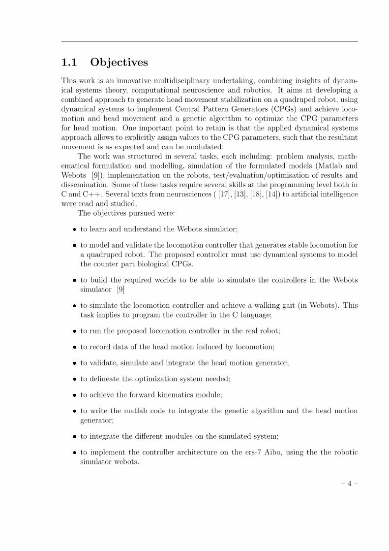
1.1 Objectives
This work is an innovative multidisciplinary undertaking, combining insights of dynam-ical systems theory, computational neuroscience and robotics. It aims at developing acombined approach to generate head movement stabilization on a quadruped robot, usingdynamical systems to implement Central Pattern Generators (CPGs) and achieve loco-motion and head movement and a genetic algorithm to optimize the CPG parametersfor head motion. One important point to retain is that the applied dynamical systemsapproach allows to explicitly assign values to the CPG parameters, such that the resultantmovement is as expected and can be modulated.
The work was structured in several tasks, each including: problem analysis, math-ematical formulation and modelling, simulation of the formulated models (Matlab andWebots [9]), implementation on the robots, test/evaluation/optimisation of results anddissemination. Some of these tasks require several skills at the programming level both inC and C++. Several texts from neurosciences ( [17], [13], [18], [14]) to artificial intelligencewere read and studied.
The objectives pursued were:
� to learn and understand the Webots simulator;
� to model and validate the locomotion controller that generates stable locomotion fora quadruped robot. The proposed controller must use dynamical systems to modelthe counter part biological CPGs.
� to build the required worlds to be able to simulate the controllers in the Webotssimulator [9]
� to simulate the locomotion controller and achieve a walking gait (in Webots). Thistask implies to program the controller in the C language;
� to run the proposed locomotion controller in the real robot;
� to record data of the head motion induced by locomotion;
� to validate, simulate and integrate the head motion generator;
� to delineate the optimization system needed;
� to achieve the forward kinematics module;
� to write the matlab code to integrate the genetic algorithm and the head motiongenerator;
� to integrate the different modules on the simulated system;
� to implement the controller architecture on the ers-7 Aibo, using the the roboticsimulator webots.
– 4 –

The robustness of this architecture will be tested on a simulated and real Aibo ofSony.
1.2 Motivation
Autonomous adaptive locomotion over irregular terrain is one important topic in roboticsresearch. There are several open questions and issues to be addressed and solved. In ourwork we address the general issue of efficiently generating movement. Generating efficientmovement is an engineering challenge because: it requires the production of signals withthe right frequencies, phases and amplitudes for multiple degrees-of-freedom (DOFs) andthe skills to coordinate these multiple DOFs. If efficiency and adaptivity is desired, itrequires the processing of multi-modal and multi-dimensional sensory inputs; the abilityto deal with dynamic, complex and unpredictable environments and adaptivity to changesin body properties.
Animals are efficient and agile to adapt to new environments. It is our motivationand belief, that nature provides us with some solutions to these problems, that is, tocontrol a lot of elements, to form specific walking patterns and provides high autonomousadaptation to various environments. Despite the large number of species and the hugecomplexity of locomotion control involving multiple redundancies, some simple commonfeatures exist.
Therefore, we take inspiration from the neural mechanisms underlying movementcontrol in animals [18] to develop a bio-inspired architecture for adaptive and autonomousgeneration of complex motor behaviors, with application to articulated robots with manyDOFs. In particular, we focus in locomotion which is a relevant and well studied areain robotics but with still a lot of open questions. Locomotion is a very challenging andhigh complex task that requires relevant features of movement control, notably timing,synchronization and accuracy but at the same time involves other high level features suchas the need to keep balance, avoid obstacles, etc.
We expect that the obtained results may be used in the development of controlsoftware that will allow robots to leave laboratories and deal with unknown environmentswith levels of adaptation, efficiency and robustness similar to those of animals. Themotivation is that the approach may find a number of applications in service tasks andwill contribute towards better rehabilitation of movement control in amputees. Therefore,a niche of research is autonomous adaptive locomotion.
1.3 Research Method
This work aims at developing a control architecture that is able to generate both locomo-tion and head stabilization for a quadruped. The proposed control architecture is basedon bio-inspired MPGs and the used robotic platform is the ers-7 Aibo robot, a quadrupedrobot. The research of this work is highly multidisciplinar and addresses the followingissues:
– 5 –
� Neural Systems used in the locomotion.
� Non-linear dynamical systems and their use to achieve robotic controllers.
� Robot locomotion.
� Quadruped Locomotion.
� Ers-7 Aibo robot, including the kinematics.
� The webots simulator.
The research made for this project enabled a good perspective over several problemsand solutions for the quadruped robot locomotion. It also opened our mind to a new setof problems that we should address in our work.
1.4 Report Structure
In chapter 2 we briefly present a state-of-the-art of work related to the one addressed inthis Master thesis. We discuss the use of nonlinear dynamical systems in the roboticsdomain, and specifically in robot locomotion. We also present some works that addressthe head motion stabilization.
In chapter 3 we describe the used tools in this work: the AIBO ers-7 and the webotssimulator.
The generic MPG used to model a biological CPG, and it is properties is presentedin chapter 4. Some examples are shown that illustrate the innovate aspect of this thesisthat applies two type of discrete movements to generate more complex behavior. Thisgeneric MPG is used to generate locomotion and head motion.
The locomotion controller proposed to generate locomotion, based on a networkstructure of coupled MPGs, is described in chapter 5. This controller implements awalking gait in the quadruped robot. We explain the required MPG parameters and thephase-differences between the different MPGs to achieve this gait. We also present theresults obtained when this controller is both simulated in Webots and implement on thereal robot.
With this locomotion architecture it is possible to change locomotion gaits by justchanging the phase-differences and parameters of each MPG.
In chapter 6, we proposed the head motion stabilization system. We describe theproposed optimization system that comprises a head motion generator and a geneticalgorithm. Because optimization is done off-line, relevant data must be recorded andmathematical treated such that it my be comparable to the one achieved by the opti-mization system. These transformations are explained in this chapter. The head motiongenerator based on the generic MPG is presented. This controller controls the 3 neckjoints that position the head.
– 6 –
The used Genetic algorithm and its functionalities such as the evaluation function(fitness) are discussed and presented in chapter 7. The obtained results, concerning theoffline optimization system are presented in this chapter.
In chapter 8 we present the obtained results when the system runs with the headmotion controller tuned as the genetic optimization system determined. The presentedresults are only simulated.
Finally, the thesis ends with conclusions and the presentation of future work.
– 7 –

Chapter 2
State of the Art
In recent years a big effort has being made to allow robots to perform autonomous tasksin unknown and unpredictable environment. Robot locomotion is an example of a chal-lenging task that requires several important features of movement control, notably timing,synchronization and accuracy, but at a very complex level involving high level featuressuch as the need to keep balance, avoid obstacles,etc.
This chapter presents the state-of-the-art of bio-inspired locomotion controllers forrobotic systems. Specifically, those that use CPGs. We briefly describe the need forthe dynamical systems approach to model controllers for locomotion and present theadvantages of such systems over more traditional approaches. We also briefly reviewsome of the works that address head motion stabilization.
2.1 Nonlinear dynamical system for movement gen-
eration
Despite the efficient controllers that have been developed for trajectory following inrobotics and the advances in the control domain which validated dynamic, robust andadaptive control techniques, the problem of generating trajectories in autonomous roboticsis still a complex, unsatisfactory solved problem. Usually, this problem requires that spaceand time constraints on robot motion must be known before hand with an high degreeof precision. Some approaches use hand-coded trajectories or pre-recorded human trajec-tories to generate trajectory templates (such as imitation learning [33] and [34]). Otherapproaches, e.g. in locomotion control, use stability criteria to do online trajectory mod-ulation [35] and [14]. However, most approaches have significant difficulties when theenvironment is dynamic and partially unknown and robust behavior must be generatedin face of uncertain sensors and a dynamically changing environment, where there is acontinuous online coupling to sensory information. In order to develop autonomous robotsystems it is required a tight coupling of planning, sensing and execution.
We address the problem of online generating trajectories by applying an approachthat uses dynamical systems, i.e., systems of differential equations.
– 8 –

There is a growing interest for using nonlinear dynamical systems for online trajec-tory generation: pattern generators for locomotion, potential field approaches for plan-ning [39]and basis field approaches for limb movements [38]. Dynamical systems of-fer multiple interesting features which make them well-suited for trajectory generationcomparatively to other methods based on finite-state machines, sine-based trajectories,ZMP-based [35] or heuristic control laws such as the Virtual Model Control [14]. Theseinclude: low computation cost which is well-suited for real time; the stability propertiesof the limit cycle behavior (i.e. perturbations are quickly forgotten); intrinsic robust-ness against small perturbations; the smooth online modulation of trajectories throughchanges in the dynamical systems parameters and phase-locking between the differentoscillators for different DOFs. Further, these systems, once coupled, produce coordinatedmultidimensional rhythms of motor activity, under the control of simple input signals.
To tackle both the complexity of movement generation and the complexity inherentto the design of dynamical systems, we assume that any movement can be decomposed insimple rhythmic and discrete primitives that we model by simple, stable, dynamical sys-tems. This movement decomposition and the chosen primitives are supported by currentneurological and human motor control findings. The basic idea is to design dynamicalsystems that can generate trajectories that have both discrete and rhythmic componentsand to easily control the switch and/or superposition between the two modes.
The vertebrates basic movements like walking and breading, are generated by thecentral nervous system [17].Despite the physical differences between vertebrate animals,little has changed in the vertebrate motor system, during the evolution. This indicatesthe existence of basics fundamental principles in the central nervous system [20].
The central pattern generator (CPG) concept is supported by studies, that show,that in the spinal cord, there exits a set of specialized neuronal networks that generatecoordinated activities that are responsible for some basic movements in vertebrates. Wetake inspiration from these systems to generate control policies for the locomotion ofrobots. Our mathematical CPGs models are based on nonlinear dynamical systems [24].These are stable limit cycle oscillators [22], that can be phase coupled to generate animallocomotion [23].
Control approaches based on CPGs and nonlinear dynamical systems are widelyused in robotics to achieve tasks which involve rhythmic motions including autonomousadaptive dynamic walking over irregular terrain [36] [11,37], juggling [39], drumming [1],and basis field approaches for limb movements [38].
Works such as [25], uses sensory feedback for the development of quadruped loco-motion controllers based on CPGs. The works of [11] and [26] explore also the feedbacksensory, with the locomotion controllers based on CPG. In [11] is developed a network ofadaptive CPGs to control the equilibrium of a biped robot. CPGs and non-linear dynam-ical systems are also used in robotics to perform tasks that involve walking on irregularterrains, [25] and [4]. Particularly, in [4] we have attempted to address the posturalproblem using this framewrok of discrete and rhythmic primitives.
Others works that use control approaches based on CPGs and nonlinear dynami-cal systems are also used in controllers that were developed for combining discrete and
– 9 –

rhythmic motor primitives in drumming and dancing tasks [1] and [27].
2.2 Head Stabilization
In this research, it is proposed a motion stabilization system of an ERS-7 AIBO quadrupedrobot, which performs its own head motion according to a feedforward controller.
Several similar works have been proposed in literature [5–8]. But these methodsconsider that the robot moves according to a scheduled robot motion plan, which implythat space and time constraints on robot motion must be known before hand as well asrobot and environment models. As such, control is based on this scheduled plan.
A bio-inspirited solution for a quadruped robot, is proposed by [6]. It is based onthe vestibulo ocular reflexes (VOR) that controls the eyes movements to stabilize theimage on the retina. This binocular solution has 9 DOF in the robot head that permits3D rotations(pitch, roll, yaw). However, binocular vision systems, such [6], requiringadditional hardware in the robot.
Other works have successfully achieved gaze stabilization, that consists on imagestabilization during head movements in space. In [7] it is propose a motion and gazestabilization based on a new adaptive approach designed Model Reference AdaptativeControl (MRAC). It is based on a feedback and feedforward controllers for a 2 DOFstruture. They modified the head motion schedule in other to minimize the actual headmotion to achieve gaze stabilization. In [31] it is proposed an adaptative visual servoingand in [32] it is proposed a feedback error learning.
In [7] is presented a head stabilization of a snake like robot. This stabilizationis achieved by controlling the neck joints that create an head motion that opposes theundulation of the robot body. They propose a method for the head direction stabilizationand another for position and direction stabilization of the head.
In our work, we propose a different methodology because we combine the nonlineardynamical systems approach and an optimization algorithm. This is possible because weuse autonomous nonlinear differential equations to generate trajectories, and these equa-tions are analytically solvable meaning that we can modulate the generated trajectoriesaccording to the dynamical parameters that we assign explicitly. This is a very importantaspect of our work.
– 10 –

Chapter 3
Tools
In this chapter we presente the most important tools used during these master tese.
3.1 Aibo ERS-7
ERS-7 robot belongs to a large family of entertainment robots, produced by SonyTM,called Aibo.On 1999 Sony released the first Aibo model, as a pet robot dog. Since thatdata several models were set in the marked.
In the beginning, it was not possible to developed software for Aibo, but in 2002,Sony release the Aibo OPEN-R Software Development Kit (SDK) that uses OPEN-Rlanguage for Aibo programming. Since then, Aibo becomes a very interesting roboticplatform for research purposes.
The ERS-7 model (fig 3.1) has 20 DOFs and is equipped with sensors that allowhim to ear, touch and dynamical interact with the environment. This sensor character-istics combined with the stability of the robot platform, makes the ERS-7 robot, a goodplataform for robotic quadruped locomotion. Apendix B shows the hardware ERS-7
Figure 3.1: ERS-7 Aibo robot
– 11 –
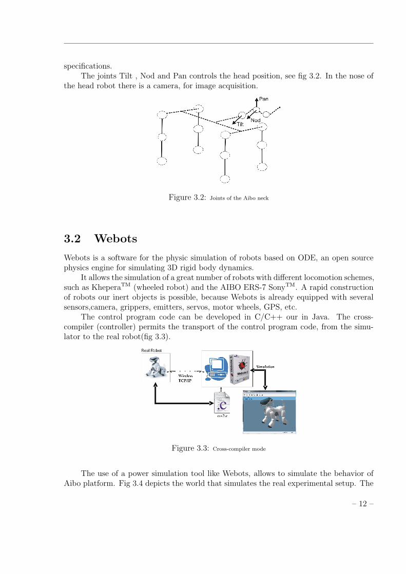
specifications.The joints Tilt , Nod and Pan controls the head position, see fig 3.2. In the nose of
the head robot there is a camera, for image acquisition.
Figure 3.2: Joints of the Aibo neck
3.2 Webots
Webots is a software for the physic simulation of robots based on ODE, an open sourcephysics engine for simulating 3D rigid body dynamics.
It allows the simulation of a great number of robots with different locomotion schemes,such as KheperaTM (wheeled robot) and the AIBO ERS-7 SonyTM. A rapid constructionof robots our inert objects is possible, because Webots is already equipped with severalsensors,camera, grippers, emitters, servos, motor wheels, GPS, etc.
The control program code can be developed in C/C++ our in Java. The cross-compiler (controller) permits the transport of the control program code, from the simu-lator to the real robot(fig 3.3).
Figure 3.3: Cross-compiler mode
The use of a power simulation tool like Webots, allows to simulate the behavior ofAibo platform. Fig 3.4 depicts the world that simulates the real experimental setup. The
– 12 –
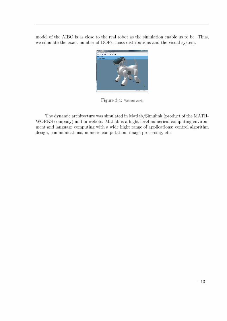
model of the AIBO is as close to the real robot as the simulation enable us to be. Thus,we simulate the exact number of DOFs, mass distributions and the visual system.
Figure 3.4: Webots world
The dynamic architecture was simulated in Matlab/Simulink (product of the MATH-WORKS company) and in webots. Matlab is a hight-level numerical computing environ-ment and language computing with a wide hight range of applications: control algorithmdesign, communications, numeric computation, image processing, etc.
– 13 –
Chapter 4
Motor Pattern Generator (MPG)
In this section we present our model of the generic MPG used to generate trajectoriesfor one DOF. First, we present in detail the architecture of each MPG which is madeof discrete and rhythmic primitives and then we discuss the intrinsic properties of thesystem that makes it suitable to generate more complex movements and online trajectoriesmodulation.
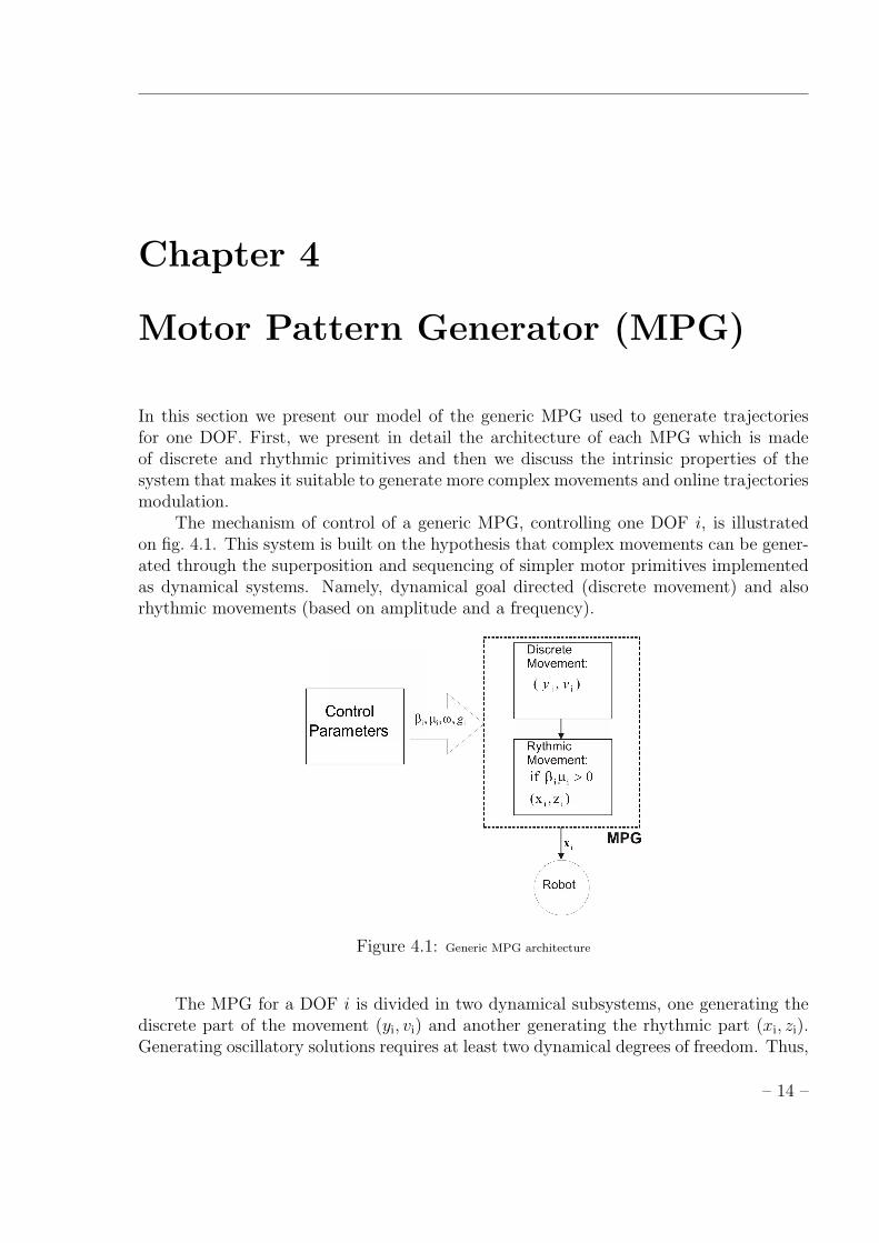
The mechanism of control of a generic MPG, controlling one DOF i, is illustratedon fig. 4.1. This system is built on the hypothesis that complex movements can be gener-ated through the superposition and sequencing of simpler motor primitives implementedas dynamical systems. Namely, dynamical goal directed (discrete movement) and alsorhythmic movements (based on amplitude and a frequency).
Figure 4.1: Generic MPG architecture
The MPG for a DOF i is divided in two dynamical subsystems, one generating thediscrete part of the movement (yi, vi) and another generating the rhythmic part (xi, zi).Generating oscillatory solutions requires at least two dynamical degrees of freedom. Thus,
– 14 –
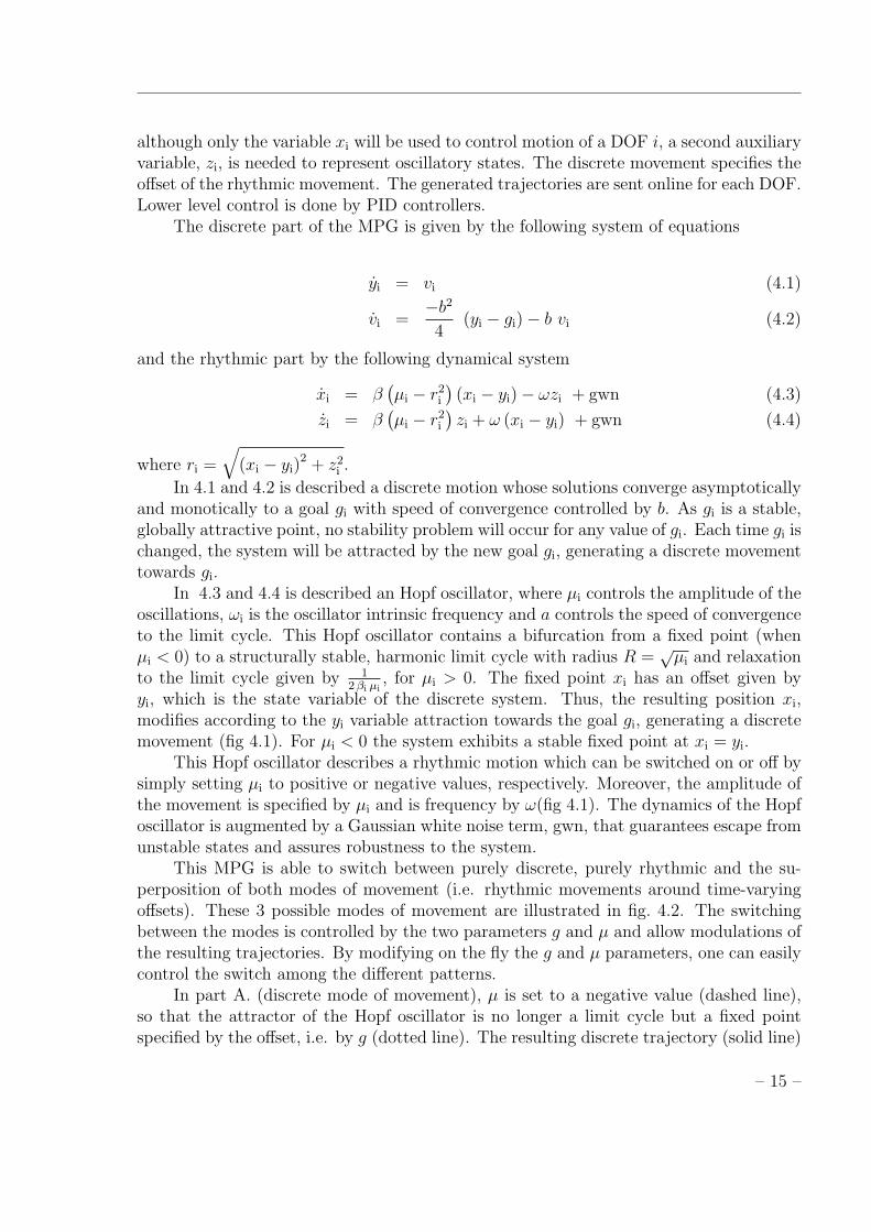
although only the variable xi will be used to control motion of a DOF i, a second auxiliaryvariable, zi, is needed to represent oscillatory states. The discrete movement specifies theoffset of the rhythmic movement. The generated trajectories are sent online for each DOF.Lower level control is done by PID controllers.
The discrete part of the MPG is given by the following system of equations
yi = vi (4.1)
vi =−b2
4(yi − gi)− b vi (4.2)
and the rhythmic part by the following dynamical system
xi = β(µi − r2
i
)(xi − yi)− ωzi + gwn (4.3)
zi = β(µi − r2
i
)zi + ω (xi − yi) + gwn (4.4)
where ri =√
(xi − yi)2 + z2
i .
In 4.1 and 4.2 is described a discrete motion whose solutions converge asymptoticallyand monotically to a goal gi with speed of convergence controlled by b. As gi is a stable,globally attractive point, no stability problem will occur for any value of gi. Each time gi ischanged, the system will be attracted by the new goal gi, generating a discrete movementtowards gi.
In 4.3 and 4.4 is described an Hopf oscillator, where µi controls the amplitude of theoscillations, ωi is the oscillator intrinsic frequency and a controls the speed of convergenceto the limit cycle. This Hopf oscillator contains a bifurcation from a fixed point (whenµi < 0) to a structurally stable, harmonic limit cycle with radius R =
õi and relaxation
to the limit cycle given by 12βi µi
, for µi > 0. The fixed point xi has an offset given byyi, which is the state variable of the discrete system. Thus, the resulting position xi,modifies according to the yi variable attraction towards the goal gi, generating a discretemovement (fig 4.1). For µi < 0 the system exhibits a stable fixed point at xi = yi.
This Hopf oscillator describes a rhythmic motion which can be switched on or off bysimply setting µi to positive or negative values, respectively. Moreover, the amplitude ofthe movement is specified by µi and is frequency by ω(fig 4.1). The dynamics of the Hopfoscillator is augmented by a Gaussian white noise term, gwn, that guarantees escape fromunstable states and assures robustness to the system.
This MPG is able to switch between purely discrete, purely rhythmic and the su-perposition of both modes of movement (i.e. rhythmic movements around time-varyingoffsets). These 3 possible modes of movement are illustrated in fig. 4.2. The switchingbetween the modes is controlled by the two parameters g and µ and allow modulations ofthe resulting trajectories. By modifying on the fly the g and µ parameters, one can easilycontrol the switch among the different patterns.
In part A. (discrete mode of movement), µ is set to a negative value (dashed line),so that the attractor of the Hopf oscillator is no longer a limit cycle but a fixed pointspecified by the offset, i.e. by g (dotted line). The resulting discrete trajectory (solid line)
– 15 –
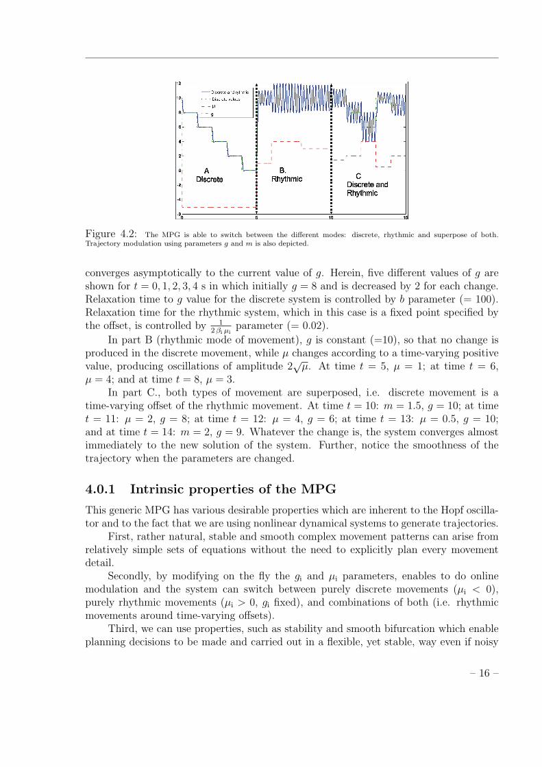
Figure 4.2: The MPG is able to switch between the different modes: discrete, rhythmic and superpose of both.Trajectory modulation using parameters g and m is also depicted.
converges asymptotically to the current value of g. Herein, five different values of g areshown for t = 0, 1, 2, 3, 4 s in which initially g = 8 and is decreased by 2 for each change.Relaxation time to g value for the discrete system is controlled by b parameter (= 100).Relaxation time for the rhythmic system, which in this case is a fixed point specified bythe offset, is controlled by 1
2βi µiparameter (= 0.02).
In part B (rhythmic mode of movement), g is constant (=10), so that no change isproduced in the discrete movement, while µ changes according to a time-varying positivevalue, producing oscillations of amplitude 2
√µ. At time t = 5, µ = 1; at time t = 6,
µ = 4; and at time t = 8, µ = 3.In part C., both types of movement are superposed, i.e. discrete movement is a
time-varying offset of the rhythmic movement. At time t = 10: m = 1.5, g = 10; at timet = 11: µ = 2, g = 8; at time t = 12: µ = 4, g = 6; at time t = 13: µ = 0.5, g = 10;and at time t = 14: m = 2, g = 9. Whatever the change is, the system converges almostimmediately to the new solution of the system. Further, notice the smoothness of thetrajectory when the parameters are changed.
4.0.1 Intrinsic properties of the MPG
This generic MPG has various desirable properties which are inherent to the Hopf oscilla-tor and to the fact that we are using nonlinear dynamical systems to generate trajectories.
First, rather natural, stable and smooth complex movement patterns can arise fromrelatively simple sets of equations without the need to explicitly plan every movementdetail.
Secondly, by modifying on the fly the gi and µi parameters, enables to do onlinemodulation and the system can switch between purely discrete movements (µi < 0),purely rhythmic movements (µi > 0, gi fixed), and combinations of both (i.e. rhythmicmovements around time-varying offsets).
Third, we can use properties, such as stability and smooth bifurcation which enableplanning decisions to be made and carried out in a flexible, yet stable, way even if noisy
– 16 –
sensory information is used to steer action. If we include sensory feedback in the MPG,sensory information will be forgotten as soon as it disappears from the environment thanksto the stability of the system. Therefore, the MPG can thus produce trajectories that arestable to perturbations.
The possibility to integrate sensory feedback terms allows robustness against per-turbations and provides the ability to smoothly recover from perturbations by meansof coupling terms in the dynamics, in contrast to other approaches such as finite statemachines [1].
Another advantage of the MPG is the fact that it is possible to parameterize thesystem by analytic approximation, which facilitates the modulation of the goal, ampli-tude and the frequency of the trajectory. Easy modulation of the goal and amplitude isshown in fig. 4.2. Since the goal and amplitude are linearly related to the vectors −→g and−→µ , simple modulation of these vectors can generate an infinite variation of stable trajec-tories. Modulation of these vectors results in smooth modulation of goal and amplitudeparameters and is thus interesting for trajectory generation in a robot.
Further, the coordination and synchronization among the DOFs, achieved throughthe coupling among the dynamics of several DOFs, provides for a smooth and an adaptivebehaviour of the complete system in face perturbations in the sensed environment. Thistype of control scheme has a wide range of applications in multi-dimensional controlproblems.
– 17 –
Chapter 5
Locomotion Generation
In this chapter is described locomotion generation for a quadruped robot. The robotplatform is the Sony ERS-7. The locomotion is based on non-linear dynamic systemsthat model a MPG (chapter 4).
5.1 Overall Architecture
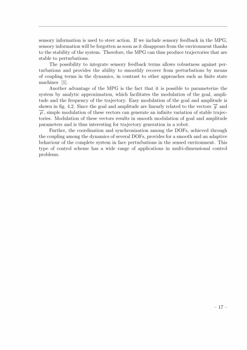
Figure 5.1: Locomotion Architecture
Fig 5.1 depicts the overall architecture used to generate locomotion. A networkstruture of MPGs generates planned trajectories for the robot hip and knee joints. EachMPG, similar to the one presented in chapter 4, controls one degree-of-freedom (DOF) ofthe robot.
– 18 –

5.1.1 Robotic Setup
The robot used to implement the forward locomotion is the model ERS-7 of the SonyAiBO. Robot description was presented in chapter 3,section 3.1.
The dog assumes a stand-up position, different from the position normally used inRoboCup [15] on the Aibo locomotion.
Locomotion is achieved by controlling 8 DOF of the robot, 2 DOFs for each limb.Considering only one limb, there are two joints in the hip (swing and flap) and one in theknee. For the locomotion, we used only the hip swing and the knee, see fig 5.2.
Figure 5.2: Scheme of the Aibo controlled DOF’s
From now on, the swing hip joint will be referred to as hip. We will also refer tothe joints as FLL[1],FLL[2],FLL[3] for the Front Left limb; FRL[1],FRL[2],FRL[3] for theFront Right limb; HLL[1],HLL[2],HLL[3] for the Hind Left limb and HRL[1],HRL[2],HRL[3]for the Hind Right limb.
In locomotion the neck joints are fixed. This means that the robot head moves withthe robot. Joints description are presented in table 5.1.
Table 5.1: Aibo DOF’s specification
DOF Description
FLL[1] Front Left Limb HipFLL[3] Front Left Limb KneeFRL[1] Front Right Limb HipFRL[3] Front Right Limb KneeHLL[1] Hind Left Limb HipHLL[3] Hind Left Limb KneeHRL[1] Hind Right Limb HipHRL[3] Hind Right Limb Knee
– 19 –
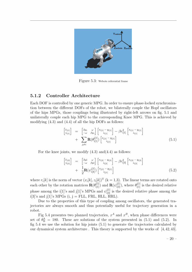
Figure 5.3: Webots referential frame
5.1.2 Controller Architecture
Each DOF is controlled by one generic MPG. In order to ensure phase-locked synchroniza-tion between the different DOFs of the robot, we bilaterally couple the Hopf oscillatorsof the hips MPGs, those couplings being illustrated by right-left arrows on fig. 5.1 andunilaterally couple each hip MPG to the corresponding Knee MPG. This is achieved bymodifying (4.3) and (4.4) of all the hip DOFs as follows:[
xi[1]
zi[1]
]=
[βµi ω−ω βµi
] [xi[1] − yi[1]
zi[1]
]− βr2
i[1]
[xi[1] − yi[1]
zi[1]
]+
∑j 6=i
R(θj[1]i[1])[xj[1] − yj[1]
zj[1]
](5.1)
For the knee joints, we modify (4.3) and(4.4) as follows:[xi[3]
zi[3]
]=
[βµi ω−ω βµi
] [xi[3] − yi[3]
zi[3]
]− βr2
i[3]
[xi[3] − yi[3]
zi[3]
]+
1
2R(ψ
j[1]i[3])
[xj[1] − yj[1]
zj[1]
](5.2)
where ri[k] is the norm of vector (xi[k], zi[k])T (k = 1,3). The linear terms are rotated onto
each other by the rotation matrices R(θj[1]i[1]) and R(ψ
j[1]i[3]), where θ
j[1]i[1] is the desired relative
phase among the i[1]’s and j[1]’s MPGs and ψj[1]i[3] is the desired relative phase among the
i[3]’s and j[1]’s MPGs (i, j = FLL, FRL, HLL, HRL).Due to the properties of this type of coupling among oscillators, the generated tra-
jectories are always smooth and thus potentially useful for trajectory generation in arobot.
Fig 5.4 presentes two planned trajectories, xA and xB, when phase differences wereset of θA
B = 180. These are solutions of the system presented in (5.1) and (5.2). Infig 5.4 we use the solution for hip joints (5.1) to generate the trajectories calculated byour dynamical system architecture . This theory is supported by the works of [4,42,43].
– 20 –
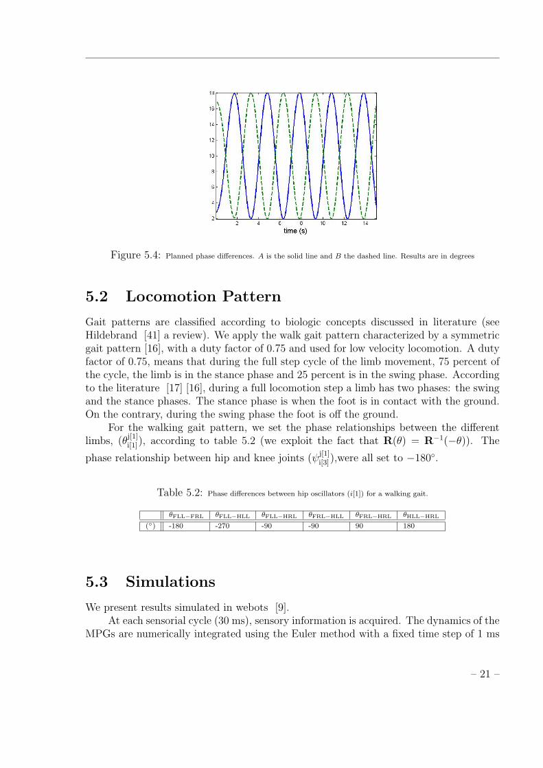
Figure 5.4: Planned phase differences. A is the solid line and B the dashed line. Results are in degrees
5.2 Locomotion Pattern
Gait patterns are classified according to biologic concepts discussed in literature (seeHildebrand [41] a review). We apply the walk gait pattern characterized by a symmetricgait pattern [16], with a duty factor of 0.75 and used for low velocity locomotion. A dutyfactor of 0.75, means that during the full step cycle of the limb movement, 75 percent ofthe cycle, the limb is in the stance phase and 25 percent is in the swing phase. Accordingto the literature [17] [16], during a full locomotion step a limb has two phases: the swingand the stance phases. The stance phase is when the foot is in contact with the ground.On the contrary, during the swing phase the foot is off the ground.
For the walking gait pattern, we set the phase relationships between the differentlimbs, (θ
j[1]i[1]), according to table 5.2 (we exploit the fact that R(θ) = R−1(−θ)). The
phase relationship between hip and knee joints (ψj[1]i[3]),were all set to −180◦.
Table 5.2: Phase differences between hip oscillators (i[1]) for a walking gait.
θFLL−FRL θFLL−HLL θFLL−HRL θFRL−HLL θFRL−HRL θHLL−HRL
(◦) -180 -270 -90 -90 90 180
5.3 Simulations
We present results simulated in webots [9].At each sensorial cycle (30 ms), sensory information is acquired. The dynamics of the
MPGs are numerically integrated using the Euler method with a fixed time step of 1 ms
– 21 –

thus specifying servo positions. Parameters were chosen in order to respect feasibility ofthe experiment and are given in tables 5.3 and 5.4.
We recorded the servo planned trajectories and the joints trajectories, xi and xi
respectively, see fig 5.1.
Table 5.3: Walking gait MPG parameters for hip joints
Amplitude(◦) y (◦) ω (rad s−1) β µi1
2βµi(s)
10 10 2.0944 0.025 25 0.8
Table 5.4: Walking gait MPG parameters for knee joints
Amplitude(◦) y (◦) ω (rad s−1) β µi1
2βµi(s)
5 40 2.0944 0.1 6.25 0.8
Fig 5.5 shows the planned trajectories (solid line) and the real trajectories (dashedline) of the front and hind hip joints.
Figure 5.5: Planned movement, xi, (solid line) and joint movement, xi, (dashed line). Results are in degrees.
Fig 5.6 presents the FLL[1] and FLL[3] real trajectories. Note the -180º phaserelationship.
The obtained duty-factor is 0.7087. Fig 5.7 shows touch sensors of each limb. Thelimbs touch the ground in this sequence: FRL,HLL,FLL,HRL.
– 22 –
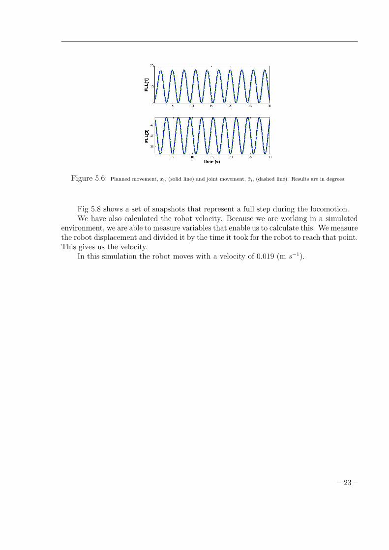
Figure 5.6: Planned movement, xi, (solid line) and joint movement, xi, (dashed line). Results are in degrees.
Fig 5.8 shows a set of snapshots that represent a full step during the locomotion.We have also calculated the robot velocity. Because we are working in a simulated
environment, we are able to measure variables that enable us to calculate this. We measurethe robot displacement and divided it by the time it took for the robot to reach that point.This gives us the velocity.
In this simulation the robot moves with a velocity of 0.019 (m s−1).
– 23 –
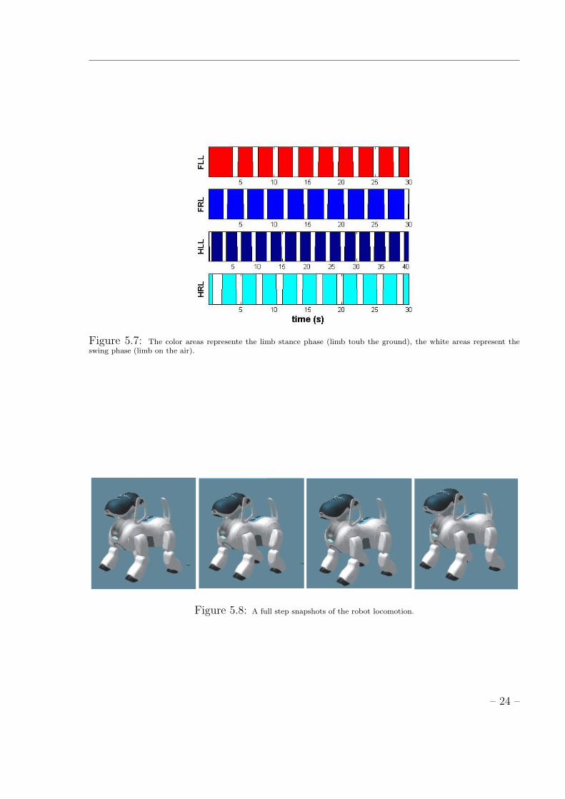
Figure 5.7: The color areas represente the limb stance phase (limb toub the ground), the white areas represent theswing phase (limb on the air).
Figure 5.8: A full step snapshots of the robot locomotion.
– 24 –

Chapter 6
Head Motion Stabilization
In the previous chapter we have presented a locomotion controller that generates a walk-ing gait for the quadruped robot. However, locomotion by itself causes head shaking.This is an important problem which must be dealt with, if we want to consider to usevisually sensory information acquired by a camera mounted over the robot head. More-over, biological systems are able to stabilize the head movement, even when they have todeal with disturbances such as changing the type of gait or adapting to the environment.
In this chapter, we will present the proposed solution to achieve head stabilization.We propose a combined approach of dynamical systems and an optimization system. Thiscombination is particularly easy to achieve using the dynamical systems approach becausethe generated trajectories are modulated according to the dynamical parameters, whichare set explicitly.
Head motion is generated by a dynamical architecture that model CPGs, similarlyto the locomotion controller presented in the previous chapter. In order to achieve thedesired head movement, opposed to the one induced by locomotion, it is necessary toappropriately tune the CPG parameters. This is achieved by optimizing these CPGparameters using a genetic algorithm (GA).
Optimization is done off-line according to the head movement induced by the loco-motion when no stabilization procedure was performed.
6.1 System Architecture
Our aim is to propose a control architecture that is able to generate locomotion for aquadruped robot and to generate head motion such as to minimize the head movementinduced by the the locomotion itself.
The overall system architecture is depicted in fig. 6.1.A locomotion controller biologically inspired in the concept of MPGs, generate hip
and knee trajectories. This controller was presented in chapter 4. These trajectories areused as input for the PID controllers of these joints.
The head movement controller is implemented as two embedded dynamical systemsand superimposes discrete and rhythmic primitives. This enables to independently control
– 25 –
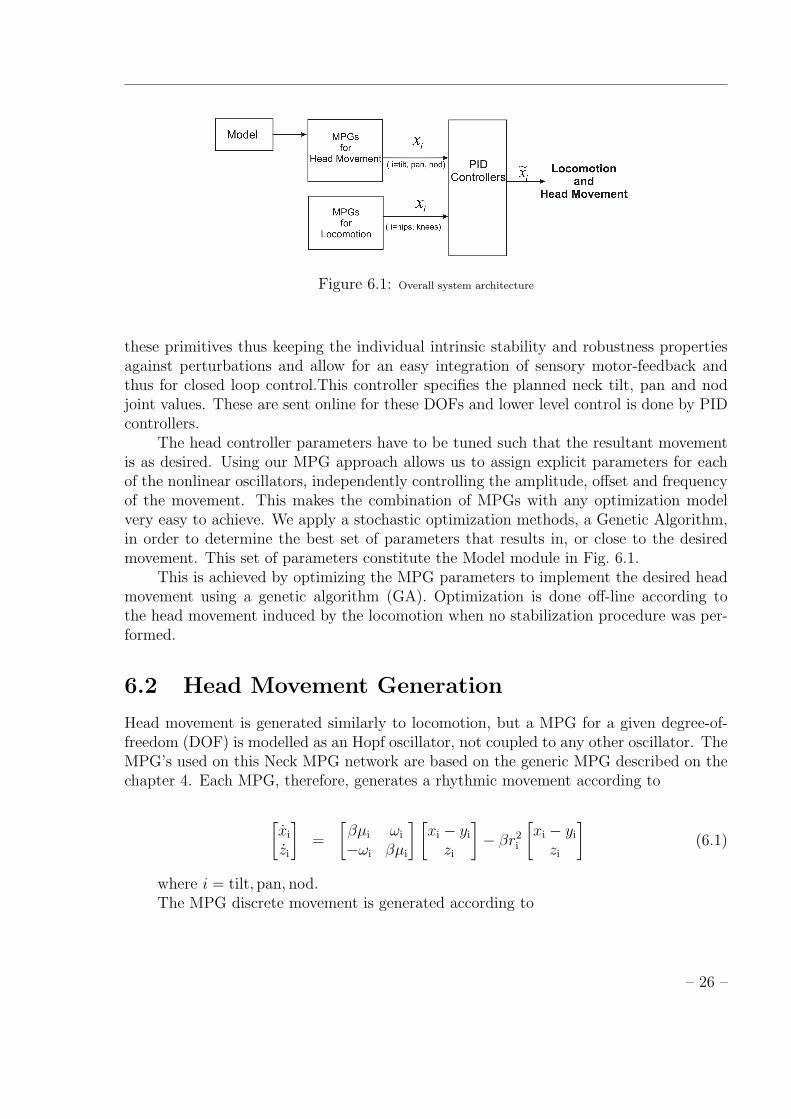
Figure 6.1: Overall system architecture
these primitives thus keeping the individual intrinsic stability and robustness propertiesagainst perturbations and allow for an easy integration of sensory motor-feedback andthus for closed loop control.This controller specifies the planned neck tilt, pan and nodjoint values. These are sent online for these DOFs and lower level control is done by PIDcontrollers.
The head controller parameters have to be tuned such that the resultant movementis as desired. Using our MPG approach allows us to assign explicit parameters for eachof the nonlinear oscillators, independently controlling the amplitude, offset and frequencyof the movement. This makes the combination of MPGs with any optimization modelvery easy to achieve. We apply a stochastic optimization methods, a Genetic Algorithm,in order to determine the best set of parameters that results in, or close to the desiredmovement. This set of parameters constitute the Model module in Fig. 6.1.
This is achieved by optimizing the MPG parameters to implement the desired headmovement using a genetic algorithm (GA). Optimization is done off-line according tothe head movement induced by the locomotion when no stabilization procedure was per-formed.
6.2 Head Movement Generation
Head movement is generated similarly to locomotion, but a MPG for a given degree-of-freedom (DOF) is modelled as an Hopf oscillator, not coupled to any other oscillator. TheMPG’s used on this Neck MPG network are based on the generic MPG described on thechapter 4. Each MPG, therefore, generates a rhythmic movement according to
[xi
zi
]=
[βµi ωi
−ωi βµi
] [xi − yi
zi
]− βr2
i
[xi − yi
zi
](6.1)
where i = tilt, pan, nod.The MPG discrete movement is generated according to
– 26 –

yi = vi (6.2)
vi =−b2
4(yi − gi)− b vi (6.3)
The control policy is the xi variable, obtained by integrating the MPGs dynamicalsystems, and represents tilt, pan and nod joint angles in our experiments. These are sentonline for the corresponding PID controllers.
Note that the final movement for each of these joints is a rhythmic motion whichamplitude of movement is specified by µi, offset by yi and is frequency by ωi.
6.2.1 Analysis of the Head Movement
When the robot walks it moves on coordinates (X, Y, Z) of a world coordinate system (anallocentric one) (fig 6.2).
Figure 6.2: Webots referential frame
We have built a GPS into the AIBO camera (in its head), that enables us to verifyhow the head effectively moves in the world coordinate system.
We recorded the (X, Y, Z) head coordinates in a world coordinate system (Fig 6.2),when the robot walks during 30 s and no head stabilization is performed. Fig 6.3 showsthis data.
In X and Y coordinates, it is possible to verify vertical and horizontal oscillations ofthe head. But there is also an oscillation in the Z coordinate. This last oscillation repre-sents a back and forward movement of the head during the locomotion. This movementis prejudicial if we want to use visual sensory information acquired by a camera mountedon the robot head.
We are interested in the opposite of this movement around the (X, Y, Z) coordinates.From now on, this data is referred to as (X, Y, Z)observed.
This data suffers several transformations in order to be used for the proposed opti-mization system. Fig. 6.4 depicts these transformations.
Firstly (first step in Fig. 6.4), the GPS data is mathematical treated to keep only theoscillations in the movement and remove the drift that the robot has in the X coordinateand also the forward movement in the Z coordinate fig 6.5. This transformation removes
– 27 –
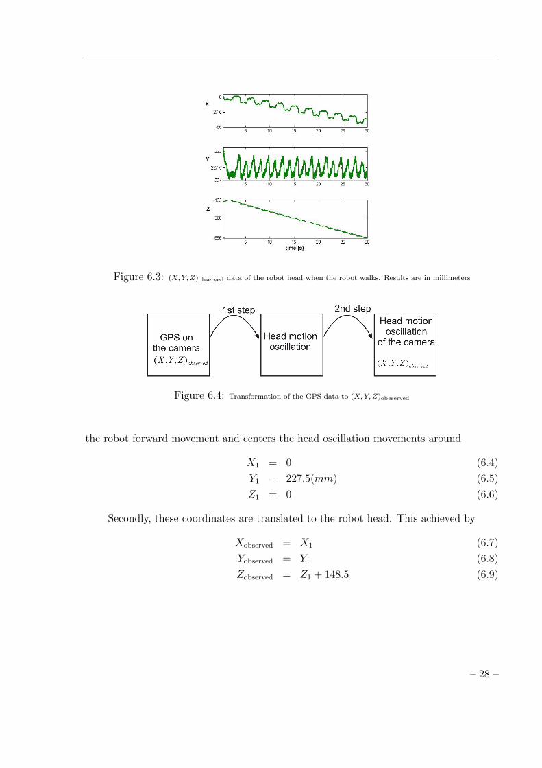
Figure 6.3: (X,Y, Z)observed data of the robot head when the robot walks. Results are in millimeters
Figure 6.4: Transformation of the GPS data to (X,Y, Z)obeserved
the robot forward movement and centers the head oscillation movements around
X1 = 0 (6.4)
Y1 = 227.5(mm) (6.5)
Z1 = 0 (6.6)
Secondly, these coordinates are translated to the robot head. This achieved by
Xobserved = X1 (6.7)
Yobserved = Y1 (6.8)
Zobserved = Z1 + 148.5 (6.9)
– 28 –
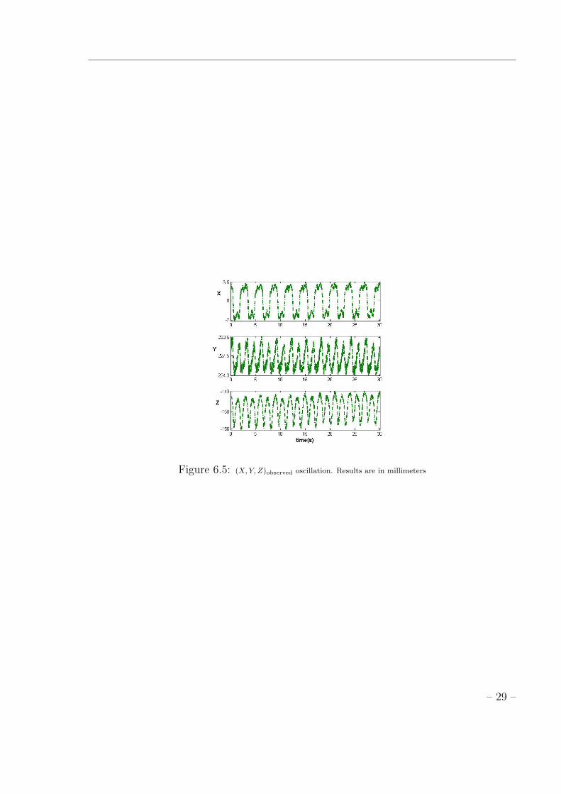
Figure 6.5: (X,Y, Z)observed oscillation. Results are in millimeters
– 29 –

Chapter 7
Optimization System
In order to implement the head motion required to reduce the camera (head) movementinduced by locomotion itself, it is necessary one or several optimal combinations of am-plitude, offset and frequency of each head oscillator. This is possible because we caneasily modulate amplitude, offset and frequency of the generated trajectories accordingto changes in the MPG parameters and these are represented in an explicit way by ourMPG. Therefore, we have to tune the MPG parameters: amplitude µi, offset Oi andfrequency ω.
The multitude of parameter combinations is large, and it is difficult to derive anaccurate model for the tested quadruped robot and for the environment. Besides, sucha model based approach would also require some post-adaptation of results (because ofbacklash, friction, etc).
In this study, the search of parameters suitable for the implementation of the requiredhead motion was carried out based on the data from actually simulated tested quadrupedrobot. The next step is to implement the same ideas in the real quadruped robot.
The optimization system runs during 30 s. This is the time for which we haveimplemented head stabilization. It is arbitrary and could have been chosen differently.We use a GA as a method of optimization of the combinations of the different MPGparameters.
The basic idea is to combine the MPG model for head movement generation withthe optimization algorithm. Fig. 7.1 illustrates a schematics of the overall optimizationsystem.
Three head MPGs ( 6.1) generate rhythmic motion for the tilt, pan and nod joints.By applying forward kinematics [12], we calculate the resulting (X, Y, Z)calculated headcoordinates in the world coordinate system. The distance between the observed andcalculated head coordinates is the evaluated criterion used to explore the parameter spaceof the MPG model to identify the head movement that minimizes the one induced bylocomotion itself.
Forward Kinematics were used according to [12] and are detailed explained in theAppendix A..
Both (X, Y, Z)observed and (X, Y, Z)calculated head coordinates must be relatively to the
– 30 –
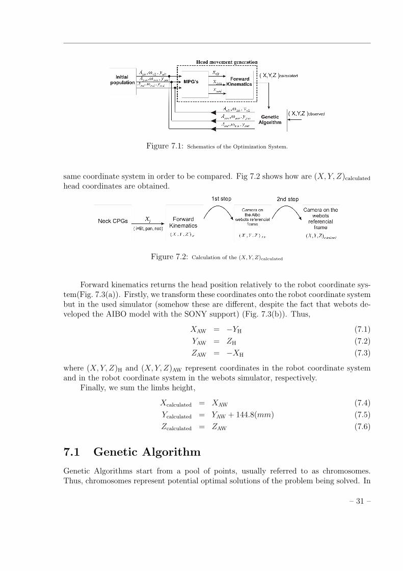
Figure 7.1: Schematics of the Optimization System.
same coordinate system in order to be compared. Fig 7.2 shows how are (X, Y, Z)calculated
head coordinates are obtained.
Figure 7.2: Calculation of the (X,Y, Z)calculated
Forward kinematics returns the head position relatively to the robot coordinate sys-tem(Fig. 7.3(a)). Firstly, we transform these coordinates onto the robot coordinate systembut in the used simulator (somehow these are different, despite the fact that webots de-veloped the AIBO model with the SONY support) (Fig. 7.3(b)). Thus,
XAW = −YH (7.1)
YAW = ZH (7.2)
ZAW = −XH (7.3)
where (X, Y, Z)H and (X, Y, Z)AW represent coordinates in the robot coordinate systemand in the robot coordinate system in the webots simulator, respectively.
Finally, we sum the limbs height,
Xcalculated = XAW (7.4)
Ycalculated = YAW + 144.8(mm) (7.5)
Zcalculated = ZAW (7.6)
7.1 Genetic Algorithm
Genetic Algorithms start from a pool of points, usually referred to as chromosomes.Thus, chromosomes represent potential optimal solutions of the problem being solved. In
– 31 –

(a) (b)
Figure 7.3: (a)Real dog referencial frame (b) Aibo webots referential frame .
order to implement a GA, it is necessary to define the representation of the search spaceand a fitness function which permits the comparison between the different chromosomes.Furthermore, genetic operators and the selection mechanism must also be defined.
One or several optimal combinations of amplitude, offset and frequency of each tilt,pan and nod oscillators are necessary in order to generate the desired head movement.Therefore, each chromosome consists in 9 MPG free parameters, as shown in fig 7.4, thatspan our vector space for the optimization.
Figure 7.4: A chromosome is made of nine MPG free parameters.
In our optimization system, we begin the GA search by randomly generating aninitial population of chromosomes.
The GA selection operator assures that chromosomes are copied to the next genera-tion with a probability associated to their fitness values. Therefore, this operator mimicsthe survival of the fittest in the natural world. Although selection assures that in thenext generation the best chromosomes will be present with a higher probability, it doesnot search the space, because it just copies the previous chromosomes. The search re-sults from the creation of new chromosomes from old ones by the application of geneticoperators. The crossover operator, takes two randomly selected chromosomes; one pointalong their common length is randomly selected, and the characters of the two parentstrings are swapped, thus generating two new chromosomes. The mutation operator, ran-domly selects a position in the chromosome and, with a given probability, changes thecorresponding value. This operator does assure that new parts of the search space areexplored, which selection and crossover could not fully guarantee.
In this work, real representation of the variables was considered. So, each vector con-sists of a vector of real values representing the decision variables of the problem. Geneticoperators were chosen taking into account this representation. In order to recombine and
– 32 –

mutate chromosomes, the Simulated Binary Crossover (SBX) and Polynomial Mutationwere considered, respectively. These operators simulate the working of the traditional bi-nary operators [3]. In order to select chromosomes for the application of genetic operators,a tournament selection was implemented.
7.2 Fitness Evaluation
The distance between the observed and calculated head coordinates is used as fitnessfunction in order to evaluate the resulting head movement.A chromosome giving a smallerdistance is evaluated as excellent and is in the best chromosomes. The fitness of the ichromosome is given by
fi =n∑j=1
√(Xj −X’j)
2 + (Yj − Y ’j)2 + (Zj − Z’j)
2 (7.7)
where j is an head position sample (because the points are generated and acquired in adiscrete manner), n is total number of samples originated during the evaluation time and(X, Y, Z), (X ′, Y ′, Z ′) represent observed and calculated head coordinates with the MPGparameters of the i chromosome, respectively.
The problem has several simple boundary constraints. In order to guarantee thefeasibility of the initial solutions and all solutions generated during the search, a repairmechanism was implemented. Thus, an infeasible solution is repaired exploring the rela-tions among variables expressed by the constraints. In this case, the search ranges of theMPG parameters were set beforehand as shown in Table 7.1 for the purpose of efficientlearning and according to the limits of the tilt, pan and nod DOFs.
Table 7.1: Search ranges of MPG parameters
Lower limit Upper limit
Atilt(◦) −75 0
ytilt(◦) −75 + Atilt
20− Atilt
2
wtilt (rad s−1) 1 12
Apan(◦) −88 88
ypan(◦) −88 + Atilt2
88− Atilt2
wpan (rad s−1) 2 12
Anod(◦) −15 45
ynod(◦) −15 + Atilt2
45− Atilt2
wnod (rad s−1) 1 12
Search for optimal parameters is carried out by performing the overall optimizationsystem over a preset number of generations.
These works are still under development, reason why the results of this studies, arenot presented in this thesis. We have also attempted other fitness functions. Firstly
– 33 –

we tried to minimize the sum of the individual square diferences between observed andcalculated (X, Y, Z) coordinates. We are currenty working in another fitness in which wecalculate the correlation between individual (X, Y, Z) observed and calculated trajectories.The idea is to obtain a measure of ”similarity” between the two.
We are also implementing the optimization system using electromagnetic algorithmto optimize the MPG parameters.
7.3 Results
We depict results when a population was established with 100 chromosomes and a presetnumber of 300 generations was set. The evaluation time, for head movement generationis 30 s.
Fig. 7.5 shows the fitness evolution of the best point for each of the 300 generations.The best point has a fitness value of 3972 that was achieved at iteration 179.
Figure 7.5: Fitness evolution of the best point for each of the 300 generations.
Table 7.2 shows tuned MPG parameters representing the best point of the 1st and300th generation.
The distance dj is given by
dj =
√(Xj −X ′j
)2+(Yj − Y ′j
)2+(Zj − Z ′j
)2(7.8)
where j is an head position sample and (X, Y, Z), (X ′, Y ′, Z ′) represent the observedand calculated head coordinates for the parameters values of the best solution found. Infig 7.6, the variation of dj is shown for the best solutions of 1st (dotted line) and 300th(solid line) generation for times ranging between t = 5 and 15 s. This figure allows abetter understanding of the evaluation of the fitness function, and represents the distance
– 34 –

Table 7.2: Search ranges of MPG parameters
1st generation 300th generation
Atilt(◦) 0.3 1.8234
ytilt(◦) 0 −0.9117
wtilt (rad s−1) 4.188 4.1120
Apan(◦) 5.5 8.0461
ypan(◦) 0 0.1232
wpan (rad s−1) 2.094 2.1304
Anod(◦) 0.3 0.4955
ynod(◦) 0 −1.1609
wnod (rad s−1) 4.188 3.9968
between observed and calculated values of head movement in each sample time of theevaluation time. In the figure we can observe that this distance is smaller for generation300.
Figure 7.6: Distance for generations 1(dotted line) and 300(solid line) and time between 5 and 15 seconds.Results arein millimeters
Fig. 7.7 depicts the time courses of the (X, Y, Z) calculated (solid line) and observed(dotted line) head movement according to the MPG parameters of the best solutionof 300th generation. Table 7.3 gives the maximal movement variation in the (X, Y, Z)coordinates for the observed and calculated movement. We conclude that the generatedmovements are quite similar in the X coordinate. The calculated movement is quitedifferent in the Z coordinate. This results from the fact that the pan joint controlsmovement in the X coordinate, while both the tilt and nod joints control the Y and Z
– 35 –

coordinates. If we are able to mimic movement in the Y coordinate, in the Z coordinatethis mimic is therefore difficult to achieve.
Figure 7.7: (X,Y, Z) calculated (solid line) and observed (dotted line) head movement according to the MPG parametersof the 300th generation best point. Results are in millimeters
Table 7.3: maximal movement variation in the (X, Y, Z)
max variation X(mm) max variation Y(mm) max variation Z(mm)Observed Movement 13.42 5.9 11.3
Calculated Movement 12.02 3.7 8.5
Fig 7.8 depicts 3D observed and calculated head movement for the best point of the300th generation. In this figure we confirm that these two movements are quite similarand main differences are observed at the Z coordinate.
– 36 –

Figure 7.8: 3D observed (dotted line) and calculated (solid line) head movement according to the MPG parametersof the 300th generation best point. START and start indicate where the observed and calculated movement started,respectively. The FINAL and the final indicate where the observed and calculated movement started, respectively
– 37 –

Chapter 8
Simulation Results
Our aim was to build a system able to eliminate or reduce the head motion of a robot thatwalks in the environment. For that, we set a dynamical controller generating trajectoriesfor the head joints such that the final head movement is opposite to the one induced bylocomotion.
In this chapter, we describe the experiment done in a simulated ers-7 AIBO robotusing Webots [9].
The ers-7 AIBO dog robot is a 18 DOFs quadruped robot made by Sony. Thelocomotion controller generates the joint angles of the hip and knee joints in the sagittalplane, that is 8 DOFs of the robot, 2 DOFs in each leg. Only walk gait is generated andtested.
The head controller generates the joint angles of the 3 DOFs: tilt, pan and nod. Theother DOFs are not used for the moment, and remain fixed to an appropriately chosenvalue during the experiments.
The AIBO has a camera built into is head.At each sensorial cycle (30 ms), sensory information is acquired. The dynamics of
the MPGs are numerically integrated using the Euler method with a fixed time step of 1ms thus specifying servo positions. Parameters were chosen in order to respect feasibilityof the experiment and are given in table 8.1.
Table 8.1: Parameter values for generating head motion
β ω (rad s−1) µi1
2βµi(s)
tilt 0.75 4.19 0.83 0.8pan 0.04 2.09 16.18 0.8nod 10.18 4.19 0.06 0.8
We expect that the proposed feedforward solution minimizes the variation of the GPScoordinates, meaning that the head remains near the same position during the experiment.We clearly observe that the X and Y coordinates of the marker position oscillate less.
– 38 –

Figure 8.1: (X,Y, Z) coordinates of the GPS positioned in the AIBO head when the robot walks during 30s. The solidlines indicate the experiment with the neck motion solution and dotted indicate the experiment in which the neck motionsolution is not implemented. Results are in millimeters
Note that there is some drift in the X coordinates, meaning the robot slightly deviatestowards is side while walking. The observed peaks in the Y coordinate reflect the finalstage of the swing phase and the begin of the stance phases of the fore legs, correspondingto an accentuated movement of the robot center of mass. This problem will be addressedin current work, by improving the locomotion controller and take into account balancecontrol [4].
As expected, we verify that the proposed feedforward solution minimizes the headmovement. This minimization is mostly verified in the X and Y coordinates as previouslyexplained. In conclusion, the proposed solution is able to minimize the head movementinduced by the locomotion, but it is not able to eliminate it. In fig 8.2 we can see a setof snapshots of the robot walking with stabilization of the head movement.
Figure 8.2: Snapshots of the robot walking in the environment. The robot moves is head in order to compensate theinduce head motion.
– 39 –

Chapter 9
Conclusion
In this thesis, we presented a controller architecture that generates both quadruped robotlocomotion and head stabilization. We developed a locomotion controller based on non-linear dynamical system, that model CPGs. This controller superimposes discrete andrhythmic movement primitives, generating smooth and stable trajectories. We imple-mented a quadruped robot walking gait pattern, by setting the limbs MPGs parametersto the correct values according to biological data.
The required head motion needed to eliminate or reduce the head shaking inducedby locomotion, is generated by CPGs built-in in the tilt, pan and nod joints. These CPGparameters are tuned by an optimization system. This optimization system combinesCPGs and a genetic algorithm. As a result, sets of parameters obtained by the evolutionstrategy were adequate for the implementation of a head movement that does not eliminatebut reduces the one induced by the locomotion.
We have attained the objectives that we initially stated within this Master thesis. Wehave give a step forward in the ASBG Group main goal of generating efficient movementfor robots with many DOFs. This work will be further integrated with other dynamicalsystems we have developed to address other locomotion related problems.
This master thesis work, allowed us to acquire knowledge in the area of bio-inspireddynamical systems and to further explore the advantages of the proposed approach. De-spite the increasing number of works made in this area, there are still a lot of openquestions. This makes the area so interesting and exciting to work on.
Currently, we are extending this work in order to achieve: generation and switchamong different gaits patterns according to the sensorial information, robust and stablelocomotion by integrating others sensory-motor feedbacks loops, control of the locomotiondirection , visually-guided movements, including feet-placement and online optimization.
For optimization, we are currently using other methods such as particle swarm [40]and electromagnetism algorithm [29].
– 40 –

Bibliography
[1] S Degallier, C P. Santos, L Righetti and A Ijspeert. Movement Generation usingDynamical Systems: a Drumming Humanoid Robot. In Humanoids’06 IEEE-RASInternational Conference on Humanoids Robots, Genova, Italy, December 4-6 2006
[2] Goldberg, D.: Genetic Algorithms in Search, Optimization, and Machine Learning,Addison-Wesley, (1989).
[3] Deb, K. Agrawal, R.B.: Simulated binary crossover for continuous search space.Complex Systems 9(2), 115–149, (1995).
[4] Castro, Luiz, Santos, C P; Oliveira, M and Ijspeert, A, ”Postural Control on aQuadruped Robot Using Lateral Titl: a Dynamical System Approach”, EuropeanRobotics Symposium EUROS 2008, Prague, 2008.
[5] Takizawa, S, Ushida, S, Okatani, T, Deguchi, K.: 2DOF Motion Stabilization ofBiped Robot by Gaze Control Strategy. 2005 IEEE/RSJ International Conferenceon Intelligent Robots and Systems (IROS 2005). Aug. 2005:3809-3814
[6] Ravi Kaushik, Marek Marcinkiewicz, Jizhong Xiao, Simon Parsons, and TheodoreRaphan: Implementation of Bio-Inspired Vestibulo-Ocular Reflex in a QuadrupedalRobot,2007 IEEE International Conference on Robotics and Automation (ICRA2007), Roma, Italy, 10-14 April 2007: 4861-4866
[7] Yamada, H.; Mori, M.; Hirose, S., Stabilization of the head of an undulating snake-like robot, 2007 IEEE/RSJ International Conference on Intelligent Robots and Sys-tems (IROS 2007), San Diego, CA, USA, Oct 29 - Nov 2, 2007 : 3566-3571
[8] Yurak Son, Takuya Kamano, Takashi Yasuno, Takayuki Suzuki,and HironobuHarada: Generation of Adaptive Gait Patterns for Quadruped Robot with CPGNetwork Including Motor Dynamic Model, Electrical Engineering in Japan, Vol. 155,No. 1, 2006
[9] O. Michel, “Webots: Professional mobile robot simulation,” International Journal ofAdvanced Robotic Systems, vol. 1, no. 1, pp. 39–42, 2004.
– 41 –
[10] A. Sproewitz, R. Moeckel, J. Maye, M. Asadpour, and A.J. Ijspeert. Adaptive lo-comotion control in modular robotics. In Workshop on Self-Reconfigurable Robot-s/Systems and Applications IROS07, pages 81-84, November 2007.
[11] Ludovic Righetti and Auke Jan Ijspeert. ”Pattern generators with sensory feedbackfor the control of quadruped locomotion”. IEEE International Conference on Roboticsand Automation ICRA 2008, California, 2008.
[12] E. Tira-Thompson, Tekkotsu: A rapid development framework for robotics, Master’sthesis, Masters Thesis, Carnegie Mellon University (2004).
[13] S. Grillner. ”Neurobiological bases of rhythmic motor acts in vertebrates”. Science,Vol. 228, No. 4696, pp. 143-149, 1985
[14] J Pratt, C Chew, A Torres, P Dilworth, G Pratt, Virtual Model Control: An intuitiveapproach for bipedal locomotion, The Int. J. of Robotics Research, 2001, 20 (2), 129-143
[15] U. Duffert and Jan Hoffmann . Reliable and Precise Gait Modeling for a QuadrupedRobot. In RoboCup 2005
[16] Milton Hildebrand. Symmetrical Gaits of the Horses, Science,New Series, Vol. 150,No.3697. (Nov. 5, 1965), pp. 701-708
[17] S. Grillner, Locomotion in Vertebrates: Central Mechanisms and Reflex Interaction.PHYSIOLOGICAL Reviews, Vol. 55, No. 2, April 1975
[18] S. Grillner Neural networks for vertebrate locomotion. Scientific American, pages48-53, January 1996.
[19] F Delcomyn. Neural basis for rhythmic behaviour in animals. Science, 210:492-498,1980
[20] Schaal, S; Kotosaka, S and Sternad, D. , Nonlinear dynamical systems as move-ment primitives. In IEEE International Conference on Humanoid Robotics. IEEE,Cambridge, MA. (2000)
[21] Shik, M; Severin, F and Orlovsky, G. Control of walking by means of electricalstimulation of the midbrain. Biophysics, 11:756-765, 1966
[22] Schoner, G and Kelso, J. , Dynamic pattern generation in behavioural and neuralsystems. Science, 239:1513-1520.(1988)
[23] Collins, J; Richmond, S, Hard-wired central pattern generators for quadruped loco-motion, Biological Cybernetics, 71, 375-385.(1994)
[24] Schoner, Gregor Dynamic theory of action-perception patterns: The timebefore- con-tact paradigm. Human Movement Science, 3: 415-439.(1994)
– 42 –

[25] Y. Fukuoka, H. Kimura, and A. Cohen. Adaptive dynamic walking of a quadrupedrobot on irregular terrain based on biological concepts. Int. J. of Robotics Research. 2003
[26] Sarah Degallier, Ludovic Righetti, and Auke Ijspeert. ”Hand placement duringquadruped locomotion in a humanoid robot: A dynamical system approach.” InProceedings of the 2007 IEEE/RSJ International Conference on Intelligent Robotsand Systems,California, 2007,pp. 2047-2052.
[27] Santos, C P; Ferreira, M; Oliveira, M; Pires, A; Degallier, S and Ijspeert, A -Choreography generation for a quadruped robot using dynamical systems, Au-tonomous Robots (submitted)
[28] S. Schaal, S. Kotosaka, D. Sternad, Nonlinear dynamical systems as movement prim-itives, in: International Conference on Humanoid Robotics. Cambridge, MA, Sept6-7, 2001, Springer, 2001, pp. 117-124.
[29] S. I. Birbil and S.C. Fang, An electromagnetism-like mechanism for global optimiza-tion, Journal of Global Optimization, 25 (2003) pp.263-282
[30] M.C. Tresch, Ph. Saltiel, and E. Bizzi. The construction of movement by the spinalcord. Nature Neuroscience, 2:162-167, 1999.
[31] Takahiro Miyashita, Koh Hosoda, Susumu Takeuchi and Minoru Asada: ”A Reflec-tive Walk Based on a Combination of Reflections”, Journal of the Robotics Societyof Japan, Vol. 18, No. 3, pp. 381 - 386, 2000
[32] T. Shibata and S. Schaal: ”Biomimetic Gaze Stabilization based on Feedback-Error-Learning with Nonparametric Regression Networks”, Neural Networks, Vol. 14, No.2, pp. 201-216, 2001
[33] A. J. Ijspeert, J. Nakanishi, S. Schaal, Learning control policies for movementimitation and movement recognition, in: Neural Information Processing System(NIPS2001), 2001.
[34] R. Blickhan, The spring-mass model for running and hopping, J. Biomechanics 22(11-12) (1989) 1217-1227.
[35] M. Vukobratovic, B. Borovac, Zero-moment point - thirty five years of its life, Inter-national Journal of Humanoid Robots 1 (1) (2004) 157-173.
[36] G Taga, Emergence of bipedal locomotion through entrainment among the neuro-musculo-skeletal system and the environment, Physica D, 1994, 75 (1-3), 190-208
[37] Y. Fukuoka, H. Kimura, and A. Cohen. Adaptive dynamic walking of a quadrupedrobot on irregular terrain based on biological concepts. Int. J. of Robotics Research,3-4, 187-202, 2003
– 43 –
[38] S Giszter, F Mussa-Ivaldi, E Bizzi. Convergent force fields organized in the frog’sspinal cord. J. of Neuroscience, 13:467-491, 1993
[39] M Buhler, S Koditscheck. Planning and control of a juggling robot. Int J of RoboticsResearch, 13(2), 101-118, 1994
[40] Pugh, Jim ; Zhang, Yizhen ; Martinoli, Alcherio. Particle swarm optimization forunsupervised robotic learning, Swarm Intelligence Symposium, 2005, p. 92-99
[41] Milton Hildebrand, Analysis of vertebrate structure. New York: John Wiley, , 1982.
[42] Cristina P. Santos, Manuel Ferreira, ”Two Vision-guided vehicles: temporal coordina-tion using nonlinear dynamical systems”, IEEE International Conference on Roboticsand Automation, ICRA 2007, April 2007, Roma, Italy.
[43] C Santos. Generating timed trajectories for an autonomous vehicle: A non-lineardynamical systems approach. In IEEE Int. Conf. On Robotics and Automation,pages 3741–3746, New Orleans, April 26-1 May 2004. IEEE.
– 44 –

Appendix A
Kinematics
This module calculates the required coordinate transformations and the correspondingangles for a given Cartesian position (inverse kinematics). This module was built usingthe Tekkotsu [12] Open Source program available at: http://www.cs.cmu.edu/ tekkot-su/index.html.
The kinematics module enables to precisely calculate the position of points on amanipulator (static kinematics), and model how they will change as each joint moves(dynamic kinematics). Further, enables to calculate which joint values will achieve adesired position (inverse kinematics) in order to produce controlled motions. On theAIBO robot, each limb is a separate manipulator, defining a chain from a common baseat the center of the robot to a different end effector (e.g. a paw or the camera). All of theAIBO’s joints are revolute. The AIBO robot has no grippers on most of its limbs, so theyare limited to non-prehensile manipulation. To account for this, the inverse kinematicsolution has been generalized in order to solve for any point on (or off) of a link, and notjust the bottom of the paw. Therefore, manipulation with any surface of the robot canbe done.
The AIBO is described as a single unbranched chain of joints separated by links.The description uses nine chains: one for each leg, one for the head (ending in the cameraas an end-effector), one for the mouth (i.e., the lower jaw), and three for the IR sensors.All these chains have a common origin at the center of the body.
Reference frames are determined by the Denavit-Hartenberg method of computingkinematic parameters. The Z axis of each link is determined by the axis of rotation forrevolute joints, or the direction of extension for prismatic joints (which is used for the IRsensors and camera). The X axis is then determined (sometimes with remaining freedom)by the relationship between consecutive links, and the Y axis is then uniquely determinedby the X and Z axes.
The origin of the base reference frame is at the center of the body. For convenience,each chain has an associated series of reference frames for each of its joints and links asdepicted in fig. A.1.
The four leg chains have five reference frames each: the base, the shoulder joint(which moves the leg forward or back), the elevator joint (which moves the leg in or out),
– 45 –

Figure A.1: Diagram taken from Sony’s documentation. The origin point is drawn as a circle in the center of the bodyfrom which the head and leg chains sprout. A ray emanating from the center of the camera’s field of view is also depicted.To each reference frame the associated coordinate axes are depicted as little triplets.
the knee joint, and the ball of the foot.
– 46 –
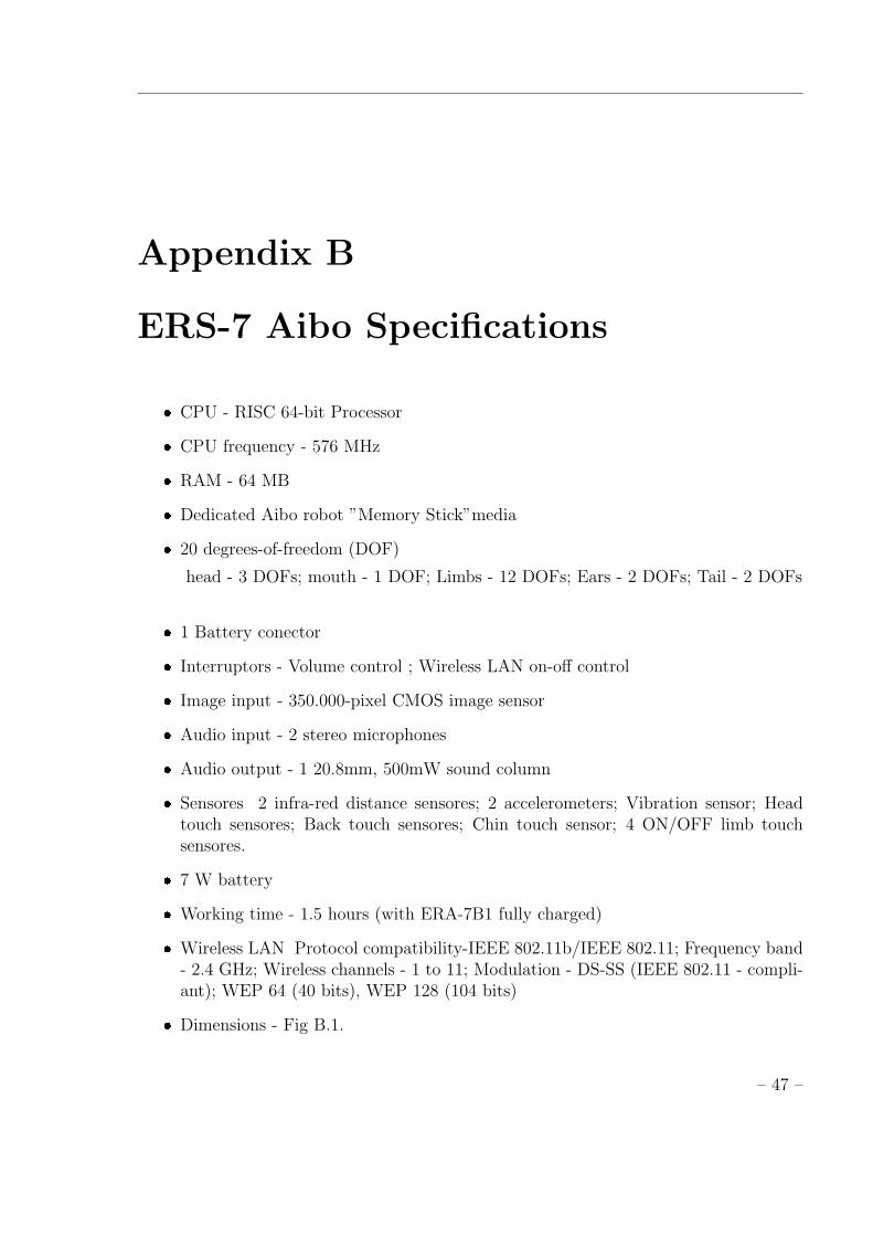
Appendix B
ERS-7 Aibo Specifications
� CPU - RISC 64-bit Processor
� CPU frequency - 576 MHz
� RAM - 64 MB
� Dedicated Aibo robot ”Memory Stick”media
� 20 degrees-of-freedom (DOF)
head - 3 DOFs; mouth - 1 DOF; Limbs - 12 DOFs; Ears - 2 DOFs; Tail - 2 DOFs
� 1 Battery conector
� Interruptors - Volume control ; Wireless LAN on-off control
� Image input - 350.000-pixel CMOS image sensor
� Audio input - 2 stereo microphones
� Audio output - 1 20.8mm, 500mW sound column
� Sensores 2 infra-red distance sensores; 2 accelerometers; Vibration sensor; Headtouch sensores; Back touch sensores; Chin touch sensor; 4 ON/OFF limb touchsensores.
� 7 W battery
� Working time - 1.5 hours (with ERA-7B1 fully charged)
� Wireless LAN Protocol compatibility-IEEE 802.11b/IEEE 802.11; Frequency band- 2.4 GHz; Wireless channels - 1 to 11; Modulation - DS-SS (IEEE 802.11 - compli-ant); WEP 64 (40 bits), WEP 128 (104 bits)
� Dimensions - Fig B.1.
– 47 –

Figure B.1: ERS-7 dimensions.
– 48 –