a close look at single point threading version 8rick.sparber.org/spt.pdf · a close look at single...
TRANSCRIPT
R. G. Sparber September 4, 2011 Page 1 of 30
A Close Look at Single Point
Threading, version 8
By R. G. Sparber
Copyleft protects this document.
1
Contents
A review of the Theory ............................................................................................. 2
The Cutter .................................................................................................................. 3
The Parting Tool Method .......................................................................................... 5
The Traditional Method ............................................................................................ 8
A Compound Set Over Greater Than 30° ........................................................... 13
A Compound Set Over Less Than 30° ................................................................ 15
The Standard Case ................................................................................................... 17
The Non-standard Case (just for doc) ..................................................................... 18
The Malcolm Method .............................................................................................. 19
That Professional Look and Feel ............................................................................. 23
Bench Work ............................................................................................................. 23
Reminder Card ........................................................................................................ 28
Acknowledgements ................................................................................................. 30
1 You are free to copy and distribute this document but not change it.

R. G. Sparber September 4, 2011 Page 2 of 30
A review of the Theory
The center of the bolt is shown as that dashed line at the top. Not drawn to scale,
we have the profile of the thread. The outer most surface of the thread is defined as
the major diameter. This is the view as you stand in front of the lathe and look
down at the thread in front of the cutter.
The pitch of a thread is the distance between identical features. I have chosen the
points or crest in this diagram. The pitch equals the reciprocal of the threads per
inch. For example, if I have 20 threads per inch, then the pitch equals �
����� =
0.05”.
By design, the thread height, H, equals approximately 0.866 times the pitch.
No matter how you run the cutter, the end result must look like this for an external
thread2. The thread profile is essentially a V groove with the top and bottom
missing. If it helps your understanding, unwrap the thread from the bolt and see it
as a long groove. The cutter runs along this groove. This mental model does not
explain the pitch but should be otherwise correct.
2 This is an American National Standard Unified External Screw Thread.

R. G. Sparber September 4, 2011 Page 3 of 30
Regardless of method, the cutter's main axis must be perpendicular to the
longitudinal axis of the lathe. This axis is the same as the center of rotation.
The Cutter I am using a threading tool that has a 60° included angle. This shape enables me to
cut an American National Standard Unified External Screw Thread profile. Any
thread can be cut if you grind the correct profile into a cutter. This is where High
Speed Steel cutters really shine. They are easy to grind to any profile.
One challenge is to form the tip of the cutter accurately. Malcolm of
gingery_machines provided me with an answer. His YouTube video
(http://www.youtube.com/watch?v=ma6kdIHwrFI) is very helpful but I have to
admit, I could not follow the math. So here is my try at it.
One note about this procedure – it does not work on cutters made from ¼ x ¼ tool
blanks given an anvil diameter of 0.25”. There isn’t enough angled flank on the
cutter.

R. G. Sparber September 4, 2011 Page 4 of 30
The cutter has been
ground with a known
included angle. The tip
is on the center line of
the cutter. The diameter
of the mic’s spindle is
known. The cutter is
held so its centerline is
perpendicular to the
mic’s spindle. A piece
of flat stock is resting
on the back side of the
spindle and the flattened
tip of the cutter. The
mic has been adjusted so the anvil and spindle just contact the cutter.
���� ��� ����
������ ������� ���
��
� ������������� � ���
�� � �!���� ���! ����� ������� ���
��
If the included angle = 60° and the diameter of the mic spindle is 0.25”, then
���� ��� � ���
"#"$$� %#�$&
�� � "#"$'(!���� ���
Since tip length = )
*�
�#+,,�
*- � ����� �
�
���.e can also write the mic reading
for a given Threads Per Inch:
��� � "
�'/01�2 %#�34&
The tip should equal�
*���.
R. G. Sparber September 4, 2011 Page 5 of 30
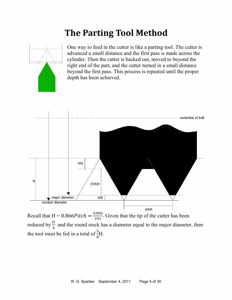
The Parting Tool Method
One way to feed in the cutter is like a parting tool. The cutter is
advanced a small distance and the first pass is made across the
cylinder. Then the cutter is backed out, moved to beyond the
right end of the part, and the cutter turned in a small distance
beyond the first pass. This process is repeated until the proper
depth has been achieved.
Recall that H = %#3550���� � �#+,,
���. Given that the tip of the cutter has been
reduced by )
* and the round stock has a diameter equal to the major diameter, then
the tool must be fed in a total of 6
+H.

R. G. Sparber September 4, 2011 Page 6 of 30
For a ¼ - 20 thread this means that H = �#+,,
����� = 0.043”; the tip has been reduced by
�#�*77
* = 0.011”; and the total feed in of the tool is
6
+ x 0.043 = 0.027”.
If the stock starts with a nominal diameter, then the total feed in of the tool = �
+8 2
6
+8 �
7
*H. But then when done cutting the thread, you must reduce the part
by a radius of )
+ to the major diameter so the crest is correct.
Donald of the gingery_machines BBS points out: “The usual argument against this
method (i.e. in favor of setting over so you're feeding effectively parallel to one
face) is to avoid the cut material from both sides of the tool bit from crowding; this
crowding causes an increase in pressure and can lead to chatter or digging the cut-
off material into the face and pushing the work piece out of alignment, leading to a
tapered thread.”
Russ of atlas_craftsman pointed out that with the cutting force on both sides of the
cutter, there is no consistent pressure on the leadscrew and halfnuts. The result is
that any backlash will show up as a wandering thread. The methods shown below
don’t have this problem.
Doc of atlas_craftsman wrote – “… I believe the helix on the lead screw
provides constant pressure towards the headstock , eliminating backlash or a

R. G. Sparber September 4, 2011 Page 7 of 30
drunken thread ...the straight in bit has pressure perpendicular , but there is
pressure to the left by the driving of the lead screw...” So I guess Russ and
Doc will have to go outside and settle the matter ;-)

R. G. Sparber September 4, 2011 Page 8 of 30
The Traditional Method The compound is set to an angle less than 30° but typically greater than 27º. For
the sake of clarity, let’s say it is 30º for now. Recall that the cutter has a 60º
included angle. On each pass, the compound is advanced into the work. Note that
the right face slides along the cut side of the V. The left face does all of the cutting.
We start with the point of the cutter on the surface of
the cylinder. Then, with the cutter off of the part, we
feed in a small amount, typically 0.005”.
The process is repeated as we march down the left
side of the groove that will become our thread.
Note that in the Parting Tool Method, we are
advancing the cross feed dial and in the Traditional
Method it is the compound dial.
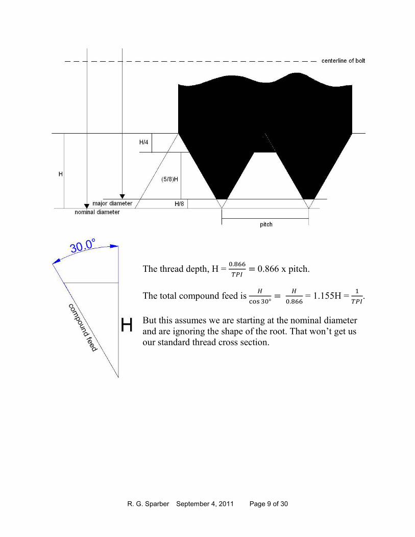
R. G. Sparber September 4, 2011 Page 9 of 30
The thread depth, H = �#+,,
����0.866 x pitch.
The total compound feed is )
9:;7�<�
)
�#+,, = 1.155H =
�
���.
But this assumes we are starting at the nominal diameter
and are ignoring the shape of the root. That won’t get us
our standard thread cross section.

R. G. Sparber September 4, 2011 Page 10 of 30
If we are starting at the nominal diameter and the
cutter's tip has been shortened by )
*, then we must
feed in
=
>)?
@
>)
9:;7�<�
7)
* 9:;7�<� %#3558 �
7
*���.
When done with all passes of the cutter, we must
remove )
+from the outside radius. This can be
done with a cutter but note that a burr may be
raised. Something like a thread clearing file will
be needed. An alternate method, mentioned by
CT2 of gingery_machines is to put a file on the
surface with the lathe running. You are not
removing much metal and you avoid raising a burr.
I will return to this subject later.

R. G. Sparber September 4, 2011 Page 11 of 30
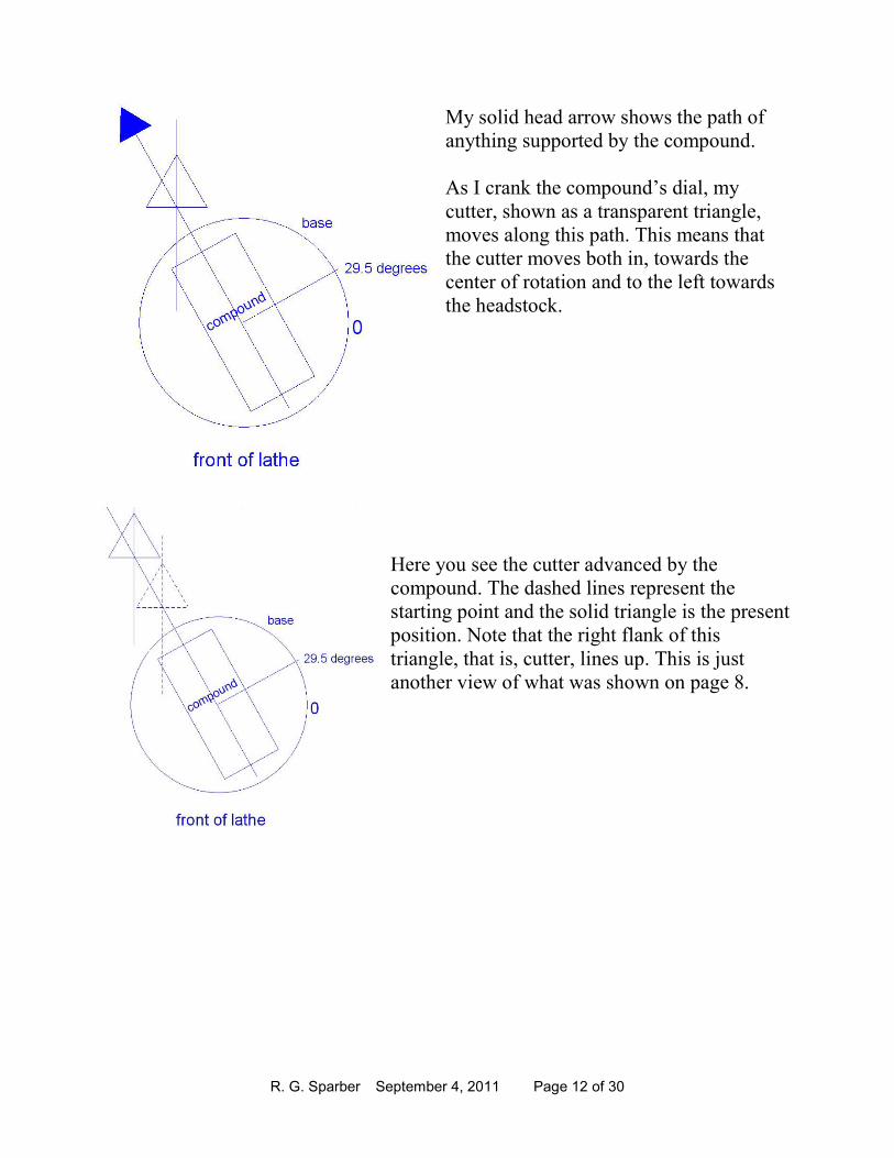
Next, let’s look at having the compound at other than 30 º. First, I better define
what I mean by this angle, at least on my Atlas-Craftsman lathe.
Here is a top view of my compound. The
circle represents my graduated scale which
reads out in degrees. On both sides of my
zero point the numbers increase. With the
compound set to 0°, my axis of movement
is perpendicular to the longitudinal axis of
the lathe.
When I set over my compound to 29.5°, it looks
like this. My dial and pointer which is on the
side reads the angle which is the same as the
angle formed by the compound’s axis and a line
perpendicular to the longitudinal axis.
Not all lathes define 0° as perpendicular to the
longitudinal axis. Some have 0° defined as
parallel to the longitudinal axis.
When in doubt, get a picture!
R. G. Sparber September 4, 2011 Page 12 of 30
My solid head arrow shows the path of
anything supported by the compound.
As I crank the compound’s dial, my
cutter, shown as a transparent triangle,
moves along this path. This means that
the cutter moves both in, towards the
center of rotation and to the left towards
the headstock.
Here you see the cutter advanced by the
compound. The dashed lines represent the
starting point and the solid triangle is the present
position. Note that the right flank of this
triangle, that is, cutter, lines up. This is just
another view of what was shown on page 8.

R. G. Sparber September 4, 2011 Page 13 of 30
A Compound Set Over Greater Than 30°
It is hard to see a ½ degree difference so let me
exaggerate the picture.
The right face of the cutter is at an angle of 30°
with respect to the lathe’s cross feed axis. The
tool path, as set by the compound angle, is at
greater than 30°, I chose 36.2°.
At the end of the first pass, the cutter has followed
the tool path which is at an angle of 36.2°.
If I pull the cutter out and look at the cut, I can
see that the tip is right on my tool path line
which is at 36.2° but the right flank has cut at
30°. Note that the V that was cut does have the
desired 60° included angle.

R. G. Sparber September 4, 2011 Page 14 of 30
Let’s take another pass with the cutter. When I
advanced the cutter with the compound, my tip will
again follow the tool path at a 36.2° angle.
Pulling the cutter out we can see how the first cut
compares to the second. We get this nasty ridge
between cuts and clearly this is not the uniform left
flank that we need.
Here is a photograph of a thread cut with the compound
angle greater than 30°. You can clearly see the ridges
on the right side. The left side doesn’t look so great
either.
Russ, the author of the picture, wrote:
“I do have to comment on the picture of the cut thread:
at the end it was taking a .060 DOC3 cut with .020 chip
on a threading insert, some stripping of the base
material would be expected. I don't think I've cut a
thread like that in 20 years, I should have run a cleanup
pass or 2.”
3 DOC means Depth Of Cut.
Picture by Russ Kepler used by permission.

R. G. Sparber September 4, 2011 Page 15 of 30
OK, so we now know how not to set the compound and what happens if we do.
A Compound Set Over Less Than 30°
Say our compound is correctly set to less than 30°. Then
the tool path is set to less than 30°. I have chosen 27°.
We start with the tip of the cutter on the surface of the
cylinder. I have drawn the tool path line through this tip.
With the cutter to the right of the cylinder, the compound
is turned to advance the cutter towards the center of
rotation. Then the first pass is made.
When the cutter is withdrawn, we see the V made by
the cutter. The bottom of the V is aligned with the tool
path line.
R. G. Sparber September 4, 2011 Page 16 of 30
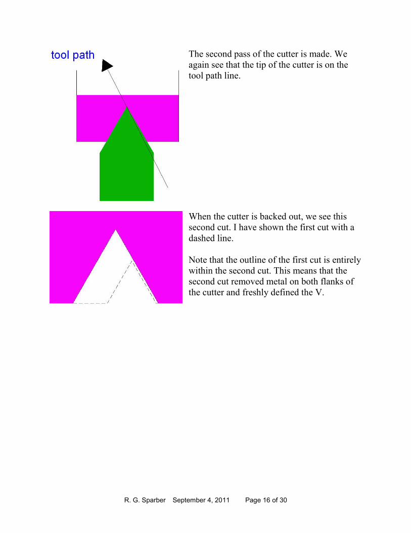
The second pass of the cutter is made. We
again see that the tip of the cutter is on the
tool path line.
When the cutter is backed out, we see this
second cut. I have shown the first cut with a
dashed line.
Note that the outline of the first cut is entirely
within the second cut. This means that the
second cut removed metal on both flanks of
the cutter and freshly defined the V.

R. G. Sparber September 4, 2011 Page 17 of 30
The Standard Case
Now we will put it all together. The compound
is set over at an angle of β° where β° is less
than 30°.
The tip of the cutter has )
* removed from its
length.
The cutter touches down at the major diameter.
We feed the cutter in a total of 6
+H on the
radius which means the compound is turned in
a total of
@
>)
ABCD<.
Recall that H = �#+,,
��� so we can say that the
total compound infeed = �#6*�
������ABCD<�.
If the compound is set over 29°, then
the total compound infeed = �#6*�
������ABC�E<� =
�#,�E
���.
For example, if we are dealing with 20 TPI, then
the total compound infeed = �#6*�
�����ABC�E<� =
�#,�E
���0.03093” ≈ 0.031”
Note that if the set over was 30°, this total compound infeed would be
�#6*�
�����ABC7�<� =
�#,�E
���0.03123” versus 0.03093”.
So for practical purposes, the total infeed is the same for 29° or 30°.
R. G. Sparber September 4, 2011 Page 18 of 30
The Non-standard Case (just for doc)
If you can’t be bothered turning the nominal diameter down to the major diameter
nor blunting the cutter tip by )
*, then this equation is for you:
Total compound infeed = ���� � �
���.
The compound should be set over at an angle between 27 and 29.5°.
Don’t forget to reduce the nominal diameter to the major
diameter when done cutting the thread. That will be a
reduction in diameter of )
* =
�#��F
���.
For example, if you are cutting 20 TPI, then the total
compound infeed is �
�� = 0.050”. Then remove
�#��F
��� =
�#��F
��
= 0.011” from the diameter.
This non-standard root will be more likely to fail. But for
many applications, this is not an issue because the part is
not stressed that much.

R. G. Sparber September 4, 2011 Page 19 of 30
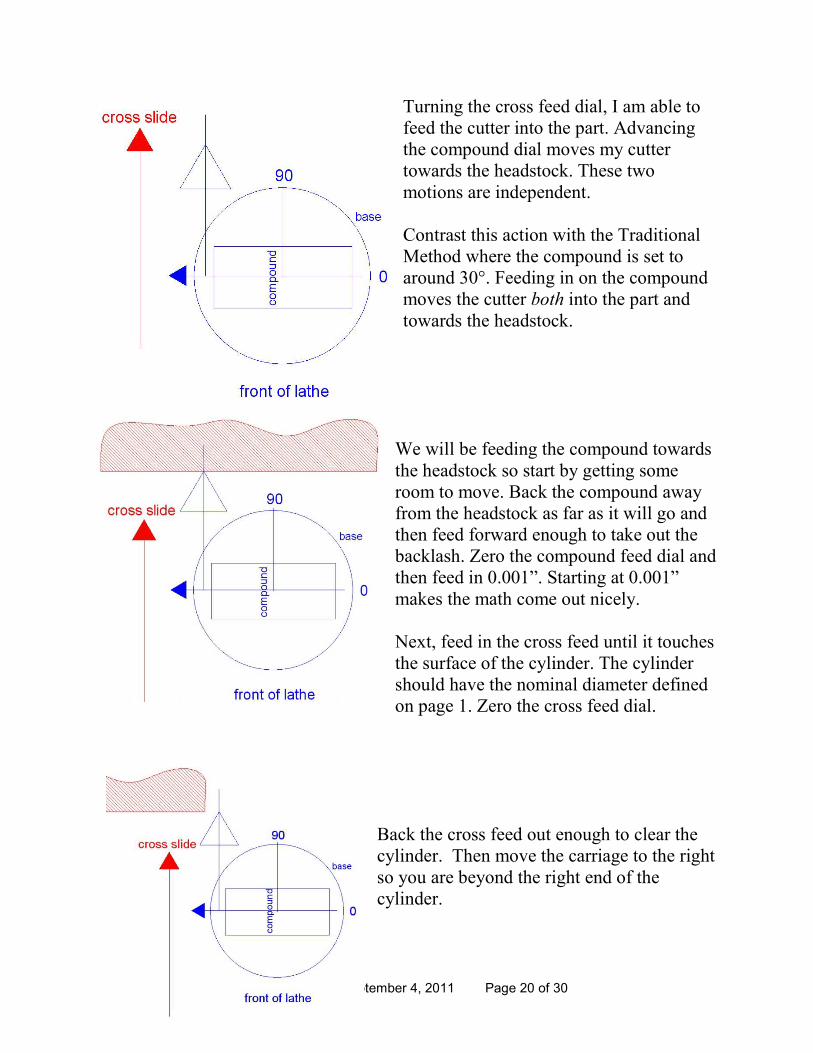
The Malcolm Method
I do not know who invented this method but my friend Malcolm was the first to
tell me about it. The advantage of this method is you can directly read thread depth
on the cross feed dial as you are cutting.
The compound is set parallel to the longitudinal
axis of the lathe. Movement forward is towards
the headstock.
The cutter is attached to the compound. The
centerline of the cutter is set perpendicular to
the lathe’s center of rotation.
R. G. Sparber September 4, 2011 Page 20 of 30
Turning the cross feed dial, I am able to
feed the cutter into the part. Advancing
the compound dial moves my cutter
towards the headstock. These two
motions are independent.
Contrast this action with the Traditional
Method where the compound is set to
around 30°. Feeding in on the compound
moves the cutter both into the part and
towards the headstock.
We will be feeding the compound towards
the headstock so start by getting some
room to move. Back the compound away
from the headstock as far as it will go and
then feed forward enough to take out the
backlash. Zero the compound feed dial and
then feed in 0.001”. Starting at 0.001”
makes the math come out nicely.
Next, feed in the cross feed until it touches
the surface of the cylinder. The cylinder
should have the nominal diameter defined
on page 1. Zero the cross feed dial.
Back the cross feed out enough to clear the
cylinder. Then move the carriage to the right
so you are beyond the right end of the
cylinder.

R. G. Sparber September 4, 2011 Page 21 of 30
Turn the cross feed dial back to zero and then advance it by 0.002” in preparation
for the first pass. We now have the cross feed dial at 0.002” and the compound dial
at 0.001”.
Start the lathe and make your first cut using the leadscrew feed. At the end of the
pass, disengage the split nut, back the cross feed out enough to clear the cylinder,
and return to the position to the right of the part.
We are now ready to take our second pass. Turn
the cross feed dial back to zero and then
advance it by the original 0.002” plus another
0.002” for a total of 0.004”.
Advance the compound dial by 0.001” to
0.002”.
We now have the cross feed dial at 0.004” and
the compound dial at 0.002”.
By accomplishing these movements, we end up
moving the cutter at a 63.4° angle with respect to the longitudinal
axis: 0.001” towards the headstock and 0.002” into the part. This is
the same as setting the compound at 90° - 63.4° = 26.6° and feeding
in 0.00224”.
Make your cut.
Again, back the cross feed away from the part and move all the way to the right.
We are now ready to take our third pass. Turn the cross feed dial back to zero and
then advance it 0.002” beyond the last cut. The cross feed dial should now read
0.006”.
Advance the compound dial 0.001” beyond the last cut. The compound dial should
now read 0.003”. We have move 0.001” closer to the headstock.
Make your cut.
R. G. Sparber September 4, 2011 Page 22 of 30
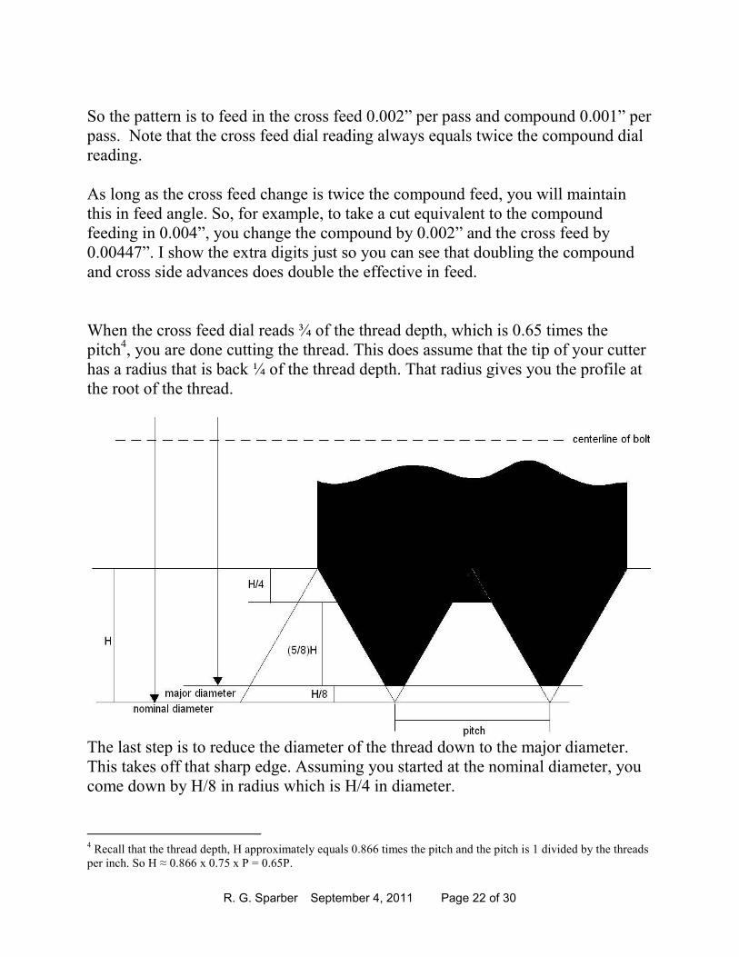
So the pattern is to feed in the cross feed 0.002” per pass and compound 0.001” per
pass. Note that the cross feed dial reading always equals twice the compound dial
reading.
As long as the cross feed change is twice the compound feed, you will maintain
this in feed angle. So, for example, to take a cut equivalent to the compound
feeding in 0.004”, you change the compound by 0.002” and the cross feed by
0.00447”. I show the extra digits just so you can see that doubling the compound
and cross side advances does double the effective in feed.
When the cross feed dial reads ¾ of the thread depth, which is 0.65 times the
pitch4, you are done cutting the thread. This does assume that the tip of your cutter
has a radius that is back ¼ of the thread depth. That radius gives you the profile at
the root of the thread.
The last step is to reduce the diameter of the thread down to the major diameter.
This takes off that sharp edge. Assuming you started at the nominal diameter, you
come down by H/8 in radius which is H/4 in diameter.
4 Recall that the thread depth, H approximately equals 0.866 times the pitch and the pitch is 1 divided by the threads
per inch. So H ≈ 0.866 x 0.75 x P = 0.65P.

R. G. Sparber September 4, 2011 Page 23 of 30
That Professional Look and Feel
As a finishing touch, it is good to form a taper on
the end of the threaded part. I’ve always done this
on my belt sander but CT2 of gingery_machines
pointed out that cutting the taper on the lathe with the threading tool gives better
results.
Bench Work Here is where I put up or shut up.
I first ground a cutter from
¼ x ¼ HSS. Rough layout
lines were scribed through
Dyken. Then I removed
most of the metal on my
bench grinder.
R. G. Sparber September 4, 2011 Page 24 of 30
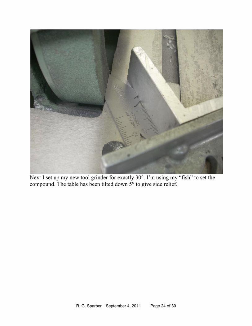
Next I set up my new tool grinder for exactly 30°. I’m using my “fish” to set the
compound. The table has been tilted down 5° to give side relief.

R. G. Sparber September 4, 2011 Page 25 of 30
The cutter is clamped to my aluminum
angle which is pressed up against the
compound. I’m taking a series of light
passes. The set up is then flipped over
and my fish again used to set 30° for
the other flank.

R. G. Sparber September 4, 2011 Page 26 of 30
This is a close up
of how well the
cutter fits the fish.
No light shines
through the
interface.
I’m using my
calibrated loupe to
put a 0.01” flat on
the tip. It took
about 20 passes
with a stone.
Ideally the flat
should be �
*���� %#%"�$&#
I was unable to
use Malcolm’s
trick with the mic
because this size
HSS does not
reach across the spindle’s diameter.
I first turned the outside diameter to the major diameter. Machinery’s Handbook
says for a ¼-20 thread, 1A class, the major diameter should be between 0.2367”
and 0.2489”. Using my wiz bang digital mic, I got a diameter of 0.24850” so I am
0.0004” below the maximum and 0.0118” above the minimum.
R. G. Sparber September 4, 2011 Page 27 of 30
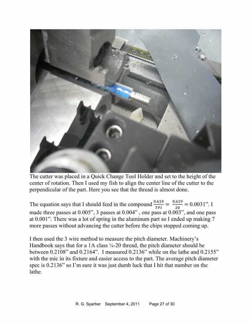
The cutter was placed in a Quick Change Tool Holder and set to the height of the
center of rotation. Then I used my fish to align the center line of the cutter to the
perpendicular of the part. Here you see that the thread is almost done.
The equation says that I should feed in the compound �#,�E
����
�#,�E
���0.0031”. I
made three passes at 0.005”, 3 passes at 0.004” , one pass at 0.003”, and one pass
at 0.001”. There was a lot of spring in the aluminum part so I ended up making 7
more passes without advancing the cutter before the chips stopped coming up.
I then used the 3 wire method to measure the pitch diameter. Machinery’s
Handbook says that for a 1A class ¼-20 thread, the pitch diameter should be
between 0.2108” and 0.2164”. I measured 0.2136” while on the lathe and 0.2155”
with the mic in its fixture and easier access to the part. The average pitch diameter
spec is 0.2136” so I’m sure it was just dumb luck that I hit that number on the
lathe.
R. G. Sparber September 4, 2011 Page 28 of 30
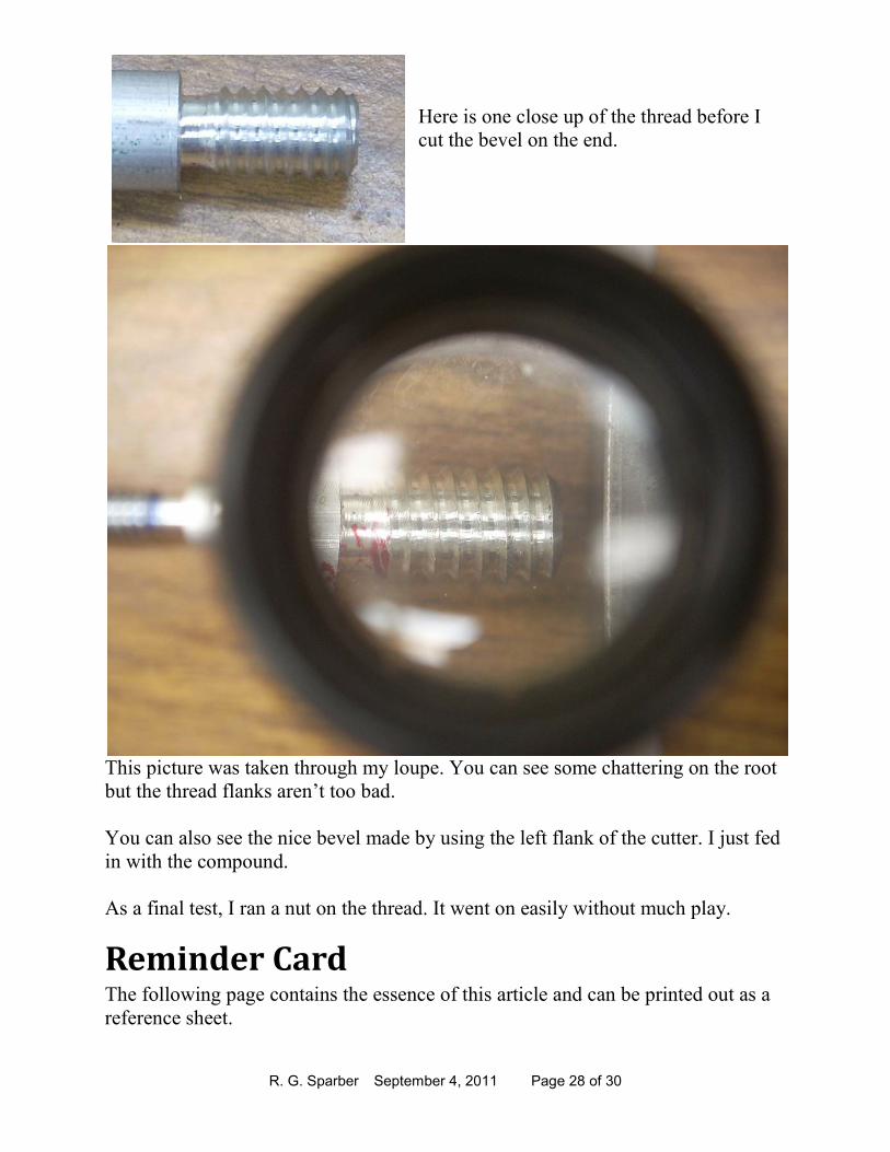
Here is one close up of the thread before I
cut the bevel on the end.
This picture was taken through my loupe. You can see some chattering on the root
but the thread flanks aren’t too bad.
You can also see the nice bevel made by using the left flank of the cutter. I just fed
in with the compound.
As a final test, I ran a nut on the thread. It went on easily without much play.
Reminder Card The following page contains the essence of this article and can be printed out as a
reference sheet.
R. G. Sparber September 4, 2011 Page 29 of 30
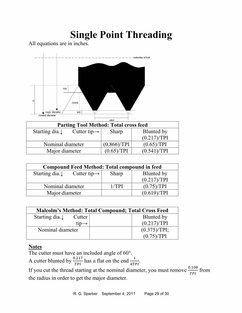
Single Point Threading All equations are in inches.
Parting Tool Method: Total cross feed
Starting dia.↓ Cutter tip→ Sharp Blunted by
(0.217)/TPI
Nominal diameter (0.866)/TPI (0.65)/TPI
Major diameter (0.65)/TPI (0.541)/TPI
Notes
The cutter must have an included angle of 60°.
A cutter blunted by �#��F
��� has a flat on the end
�
*���.
If you cut the thread starting at the nominal diameter, you must remove �#��+
��� from
the radius in order to get the major diameter.
Compound Feed Method: Total compound in feed
Starting dia.↓ Cutter tip→ Sharp Blunted by
(0.217)/TPI
Nominal diameter 1/TPI (0.75)/TPI
Major diameter (0.619)/TPI
Malcolm’s Method: Total Compound; Total Cross Feed
Starting dia.↓ Cutter
tip→
Blunted by
(0.217)/TPI
Nominal diameter (0.375)/TPI;
(0.75)/TPI

R. G. Sparber September 4, 2011 Page 30 of 30
Acknowledgements
Thanks to Donald of gingery_machines for pointing out the problem with the
Parting Tool Method. Thanks to Walter of atlas_craftsman for helping me
understand the effect of setting the compound at less than 30°. Thanks to Russ of
atlas_craftsman for explaining how the Parting Tool Method can cut a wandering
thread. Thanks to CT2 of gingery_machines for seeing that the compound’s feed
tells you thread depth when using the Traditional Method, mentioning an alternate
way to cut the taper on the end, and how to avoid a burr as the nominal diameter is
reduced to the major diameter. Thanks to doc of atlas_craftsman for pointing out
why you don’t get a wandering thread with the Parting Method, helping me solve
the mystery of the compound set over value, and questioning the thread profile
plus checking overall clarity of the article. Thanks to Bill of atlas_craftsman for
explaining the effects of setting the compound over more than 30°. Thanks to Russ
Kepler for testing the effect of compound angle and taking the picture. Thanks to
Bruce of atlas_craftsman for suggesting that I include the tip width equation.
Thanks to Chris for noticing that most of the figures were up-side-down. Last but
certainly not least is Malcolm from gingery_machines for his patience as he
carefully explained his method to me.
These generous people again demonstrate that “all of us are smarter than any one
of us”.
I welcome your comments and questions.
Rick Sparber