a cationic diode based on asymmetric nafion film deposits · a cationic diode based on asymmetric...
TRANSCRIPT
A Cationic Diode Based on Asymmetric Nafion Film DepositsDaping He,† Elena Madrid,† Barak D. B. Aaronson,† Lian Fan,‡ James Doughty,‡ Klaus Mathwig,§
Alan M. Bond,∥ Neil B. McKeown,⊥ and Frank Marken*,†
†Department of Chemistry, University of Bath, Claverton Down, Bath BA2 7AY, U.K.‡Department of Biology and Biochemistry, University of Bath, Claverton Down, Bath BA2 7AY, U.K.§Pharmaceutical Analysis, Groningen Research Institute of Pharmacy, University of Groningen, P.O. Box 196, 9700 AD Groningen,The Netherlands∥Monash University, School of Chemistry, Clayton, Vic 3800, Australia⊥EastChem School of Chemistry, University of Edinburgh, David Brewster Road, Edinburgh, EH9 3FJ, U.K.
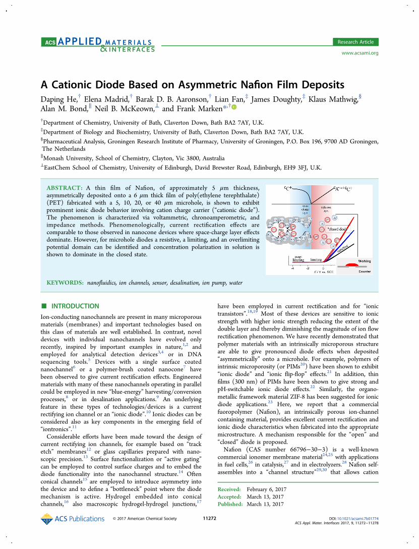
ABSTRACT: A thin film of Nafion, of approximately 5 μm thickness,asymmetrically deposited onto a 6 μm thick film of poly(ethylene terephthalate)(PET) fabricated with a 5, 10, 20, or 40 μm microhole, is shown to exhibitprominent ionic diode behavior involving cation charge carrier (“cationic diode”).The phenomenon is characterized via voltammetric, chronoamperometric, andimpedance methods. Phenomenologically, current rectification effects arecomparable to those observed in nanocone devices where space-charge layer effectsdominate. However, for microhole diodes a resistive, a limiting, and an overlimitingpotential domain can be identified and concentration polarization in solution isshown to dominate in the closed state.
KEYWORDS: nanofluidics, ion channels, sensor, desalination, ion pump, water
■ INTRODUCTION
Ion-conducting nanochannels are present in many microporousmaterials (membranes) and important technologies based onthis class of materials are well established. In contrast, noveldevices with individual nanochannels have evolved onlyrecently, inspired by important examples in nature,1,2 andemployed for analytical detection devices3,4 or in DNAsequencing tools.5 Devices with a single surface coatednanochannel6 or a polymer-brush coated nanocone7 havebeen observed to give current rectification effects. Engineeredmaterials with many of these nanochannels operating in parallelcould be employed in new “blue-energy” harvesting/conversionprocesses,8 or in desalination applications.9 An underlyingfeature in these types of technologies/devices is a currentrectifying ion channel or an “ionic diode”.10 Ionic diodes can beconsidered also as key components in the emerging field of“iontronics”.11
Considerable efforts have been made toward the design ofcurrent rectifying ion channels, for example based on “tracketch” membranes12 or glass capillaries prepared with nano-scopic precision.13 Surface functionalization or “active gating”can be employed to control surface charges and to embed thediode functionality into the nanochannel structure.14 Oftenconical channels15 are employed to introduce asymmetry intothe device and to define a “bottleneck” point where the diodemechanism is active. Hydrogel embedded into conicalchannels,16 also macroscopic hydrogel-hydrogel junctions,17
have been employed in current rectification and for “ionictransistors”.18,19 Most of these devices are sensitive to ionicstrength with higher ionic strength reducing the extent of thedouble layer and thereby diminishing the magnitude of ion flowrectification phenomenon. We have recently demonstrated thatpolymer materials with an intrinsically microporous structureare able to give pronounced diode effects when deposited“asymmetrically” onto a microhole. For example, polymers ofintrinsic microporosity (or PIMs20) have been shown to exhibit“ionic diode” and “ionic flip-flop” effects.21 In addition, thinfilms (300 nm) of PIMs have been shown to give strong andpH-switchable ionic diode effects.22 Similarly, the organo-metallic framework material ZIF-8 has been suggested for ionicdiode applications.23 Here, we report that a commercialfuoropolymer (Nafion), an intrinsically porous ion-channelcontaining material, provides excellent current rectification andionic diode characteristics when fabricated into the appropriatemicrostructure. A mechanism responsible for the “open” and“closed” diode is proposed.Nafion (CAS number 66796−30−3) is a well-known
commercial ionomer membrane material24,25 with applicationsin fuel cells,26 in catalysis,27 and in electrolyzers.28 Nafion self-assembles into a “channel structure”29,30 that allows cation
Received: February 6, 2017Accepted: March 13, 2017Published: March 13, 2017
Research Article
www.acsami.org
© 2017 American Chemical Society 11272 DOI: 10.1021/acsami.7b01774ACS Appl. Mater. Interfaces 2017, 9, 11272−11278

transport through sulfonate-lined hydrophilic channels (Figure1) within a hydrophobic fluorocarbon matrix.31,32 Thenegatively charged channels allow permanent uptake andconduction of guest molecules, in particular hydrophobiccations.33,34
In this report, Nafion is applied as a thin (approximately 5μm thick) film onto a microhole in a poly ethylene-terephthalate (PET) substrate. The voltammetric characteristicsof the resulting “asymmetric” device are compared to thecorresponding “symmetric” case with Nafion applied to bothsides of the PET substrate. It is demonstrated that only the“asymmetric” case results in current rectification or ionic diodephenomena. More generally, it is shown that a macroscopicasymmetry in the membrane|aqueous electrolyte interface onopposite sides of the membrane introduces effects that areusually associated with microscopically asymmetric nanoconedevices. The physical reasons for the rectification effects areassociated with ionomer conductivity in the “open” diode stateand with concentration polarization (defined here as adiffusional transport overpotential due to a concentrationgradient in the electrolyte) in the external electrolyte close tothe PET microhole for the “closed” diode state.
■ EXPERIMENTAL SECTIONChemical Reagents. Nafion-117 (5 wt % in a mixture of lower
aliphatic alcohols and water), concentrated hydrochloric acid (37%),sodium hydroxide (≥98%), concentrated nitric acid (69.0%),concentrated perchloric acid (70%), sodium chloride, potassiumchloride, and rhodamine B (97%) were obtained from Sigma-Aldrichor Fisher Scientific and used without further purification. Solutionswere prepared under ambient conditions in volumetric flasks withultrapure water of resistivity 18.2 MΩ cm from an ELGA PurelabClassic system.Instrumentation. Electrochemical data (for both voltammetry and
impedance) were recorded at T = 20 ± 2 °C on a potentiostatedsystem (Ivium Compactstat). A classic 4-electrode electrochemical cellsimilar to that employed in previous membrane conductivity studies35
was used. The membrane separates two tubular half-cells (15 mm
diameter), one with the Pt wire working and saturated calomel (SCE)sense electrode (tied together) and the other with the SCE referenceand Pt wire counter electrodes (tied together) (see scheme in Figure2). The cell when assembled has the shape of a “U” and is therefore
referred to as “U-cell”. Fluorescence imaging experiments wereperformed on a Nikon Eclipse 90i. For fluorescence analysis,rhodamine B was mixed with Nafion-117 (5 wt %) solution to makea solution (approximately 10 μM of rhodamine B), which was thenapplied to the PET films.
Procedure. In order to form films of Nafion on PET substrates(obtained with 5, 10, 20, 40 μm diameter hole in 6 μm thick PET fromLaser-Micro-Machining Ltd., Birmingham, UK), 10 μL Nafionsolution was applied to a PET film on a glass substrate (precoatedwith a thin layer of 1% agarose gel to avoid Nafion passing through themicrohole) by solution-casting. With a glass rod the Nafion solutionwas spread evenly over the PET to give a 1 cm2
film, which afterdrying produced a thin uniform coating of typically 5 μm thickness.When peeled off the substrate, asymmetric Nafion deposits on thePET microhole are achieved (see electron micrographs in Figure 2C).For symmetric deposits the deposition was repeated on the oppositeside. In order to image the Nafion film fluorescence image stacks wereobtained (see Figure 2) for an asymmetric (one-sided) deposit (Figure2A) and for a symmertic (double-sided) deposit (Figure 2B). Inelectrochemical measurements with asymmetric deposits the workingelectrode was always located on the side of the Nafion film.
■ RESULTS AND DISCUSSIONNafion Film Microhole Electrochemistry I: Film
Characterization. Fluorescence microscopy with rhodamineB stain (Figure 2) reveals the presence of a uniform ∼5 μmthick film of Nafion coated over a 20 μm diameter microhole in
Figure 1. Molecular structure of Nafion and schematic representationof the cation (C+) transport channel formed via self-assembly. Figure 2. Schematic drawing (not to scale) of the experimental 4-
electrode arrangement and fluorescence images for (A) single-sided/asymmetric or (B) double-sided/symmetric Nafion coated (andrhodamine B stained) PET film with 20 μm microhole. Differencesin cross-sectional view in top and bottom layer appearance are believedto be linked to light distribution artifacts. (C) SEM images showingPET side for asymmetric Nafion deposits on 40 μm, 20 μm, 10 μm,and 5 μm microholes.
ACS Applied Materials & Interfaces Research Article
DOI: 10.1021/acsami.7b01774ACS Appl. Mater. Interfaces 2017, 9, 11272−11278
11273

a PET substrate. When the Nafion is applied in two steps fromboth sides a “sandwich-like” structure is obtained intercon-nected through the microhole. These sandwich-films are thenplaced between two electrochemical half-cells (Figure 2) toallow 4-electrode voltammetric measurements.Figure 3 shows cyclic voltammetry data for the Nafion films.
Three cases are shown: (i) PET film with an empty 20 μm
diameter hole, (ii) a similar film but with Nafion deposited onboth sides, and (iii) a similar film but with Nafion depositedonly on one side. For data represented in Figure 3A, aqueous10 mM HCl solutions are present on both sides of the cell. Inthe absence of Nafion (black line) the currents are dominatedby the specific resistivity of the aqueous electrolyte solutionfilling the pore and a typical “Ohmic” slope with R = 150 kΩ isrecorded. With the help of eq 1 for left access, transit, and rightaccess resistivity for a microhole,36,37 this Ohmic slope can bereconciled with the known specific resistivity of aqueous 10mM HCl, κ = 0.412 Ω−1m−1.38
κ π= + +⎜ ⎟⎛
⎝⎞⎠R
rLr r
1 14
142 (1)
In this equation the microhole resistance R is given by themicrohole radius, r, the microhole length, L, and the specificconductivity of the electrolyte, κ.With Nafion applied on both sides (blue line) the current
clearly increases due to the locally higher concentration of ioniccharge carriers (i.e., protons in Nafion) within the microholeregion. The shape of the voltammetric response is againsymmetric and dominated by an “Ohmic” slope. With eq 1 thespecific resistivity for Nafion can be estimated as κ = 3.6Ω−1m−1, which seems realistic.39
Perhaps interestingly, for the asymmetric case (Figure 3A redline) “ionic diode” or current rectification behavior is observed
with a higher current at positive bias (consistent with resistivebehavior) and a lower current at negative bias, as compared tothe empty hole response (consistent with a limiting behavior).Figure 3B shows data for the asymmetric deposit as a functionof the electrolyte concentration. Both, currents in the “closed”state and currents in the “open” state increase with ionicstrength. The effects on the near-steady state (or time-independent) current signals due to ionic strength and ofmicrohole size are reported in more detail below.In Figure 3C, cyclic voltammetry data are shown for both 10
mM HCl and 10 mM NaOH environments. Consistently, ionicdiode effects are observed with the “open” state always in thepositive potential range. This observation is related to theNafion structure (in contrast to recent reports of “switching”diode polarity with pH22) and ascribed here to the fact thatNafion remains a cation conductor in aqueous HCl (protontransport through Nafion) and in aqueous NaOH (sodiumcation transport through Nafion). For both, protons or Na+
cations, similar effects arise at the Nafion | electrolyte interfacewith concentration polarization and cation space charge layereffects at the smaller microhole interface linked to the currentrectification effect. The higher currents seen for the experimentin 10 mM HCl (compared to currents for 10 mM NaOH) canbe explained with the higher proton mobility in Nafion.40
With a scan rate of 50 mVs−1, cyclic voltammetry responsesappear to be dominated by near-steady state behavior, but thereare underlying transient processes that can be revealed, forexample, by chronoamperometry. Figure 3D shows typicalopen/closed transients when switching the ionic diode between+1.0 V and −1.0 V. Transient responses with a typical timeconstant of approximately 0.1 s (and underlying charge oftypically Qt = 20 μC, see Figure 3D) are observed for bothdiode opening and diode closing processes. It seems likely thatthe transient component of the current response is mainlyassociated with transport of cations, which could implyformation of either a “polymer space charge region” or a“solution concentration polarization region” resulting in theclosed diode state. Nafion has a density of approximately 1.67 gcm−340 and a molecular mass of approximately 1100 g per molof sulfonate functional group. For a “plug” of 20 μm diameterand 5 μm length this amounts to a weight of 2.6 ng andtherefore a charge of 2.4 pmol (= 0.23 μC). The observedtransient charge during switching is 2 orders of magnitudehigher and therefore more likely to be associated withconcentration polarization in solution. For a microelectrodeconcentration polarization should result in an estimated timeconstant of roughly τ = r2/D or here approximately 0.1 s,consistent with the experiment.An alternative approach to the characterization of transient
phenomena is based on electrochemical impedance spectros-copy. Figure 4 shows impedance data for (A) the PET film withempty microhole, (B) the symmetric Nafion deposit, and (C)the asymmetric Nafion deposit. For the empty microhole, avoltage-independent spectrum is obtained with a classicsemicircle indicative of RC-parallel behavior. In fact theequivalent circuit shown as inset in Figure 4A can be employedto fit the data to give R1 = 1.3 kΩ (consistent with bulksolution resistance), R2 = 148 kΩ (consistent with onlymicrohole and access region resistance, see eq 1), and C = 0.8nF (consistent with PET film capacitance).Figure 4B shows impedance spectroscopy data for the PET
microhole coated symmetrically with Nafion. Again a potentialindependent impedance is observed with give R1 = 0.9
Figure 3. (A) Cyclic voltammograms (scan rate 50 mVs−1) for PETfilm with a 20 μm diameter microhole in a “U-cell” containing aqueous10 mM HCl on both sides of the PET film showing results for (i) anempty pore, (ii) symmetrically deposited Nafion, and (iii) asymmetri-cally deposited Nafion film. (B) Cyclic voltammograms for anasymmetric Nafion film immersed in 1 mM HCl, 10 mM HCl, and100 mM HCl on both sides of the PET film with rectification ratios 13,15, 7, respectively. (C) Cyclic voltammograms for an asymmetricNafion film immersed in 10 mM HCl and in 10 mM NaOH withrectification ratio 15 and 13, respectively. (D) Chronoamperometrydata for an asymmetrically deposited Nafion film immersed in 10 mMHCl when switching the potential between −1 V and +1 V.
ACS Applied Materials & Interfaces Research Article
DOI: 10.1021/acsami.7b01774ACS Appl. Mater. Interfaces 2017, 9, 11272−11278
11274

kΩconsistent with bulk resistance for both aqueous solutionand the polymer region outside the access region), R2 = 14 kΩ(consistent with microhole and access Nafion resistance withinthe polymer), and C = 0.7 nF (consistent with PET filmcapacitance). Figure 4C shows data for the asymmetricallydeposited Nafion film and for this case clear changes inimpedance as a function of applied potential are noted. Thehigh frequency semicircle remains (for −0.1/0.0/0.1 V appliedpotential, respectively) with R1 = 0.18/0.83/1.3 kΩ and C =0.6 nF at all three potentials. Parameter R2 = 99/63/40 kΩmostly reflects the internal resistance in the Nafion film, whichappears to go down when the diode “opens”. Intriguingly, asecond nonideal semicircle is observed (Figure 4C) with a timeconstant of approximately 0.1 s order of magnitude, consistentwith transient phenomena during opening/closing processes ofthe ionic diode. This time constant is proposed to be againassociated with concentration polarization.Nafion Film Microhole Electrochemistry II: Anion
versus Cation Effects. The effect of anions and cations areinvestigated, as well as ionic strength imbalances in left andright half-cells, in order to better understand “cationic diode”processes of the Nafion asymmetrically deposited ontomicrohole-containing PET film. Figure 5A shows cyclicvoltammetry data for aqueous 10 mM acids: HCl, HNO3,and HClO4. For the asymmetrically deposited Nafion film,reproducible diodes (current rectifiers) are observed in all threecases. The effect of chloride, nitrate, or perchlorate anionsremain insignificant.In contrast, when investigating the effect of the electrolyte
cation, much more obvious changes in diode behavior areobserved (Figure 5B). Currents for the open diode areconsiderably higher in the presence of protons compared tothose for Na+ or K+. This is consistent with a higher mobilityfor protons relative to Na+ and K+. Values for ion diffusivitywithin Nafion41 in the presence of 1 mol dm−3 aqueouschloride solution have been reported as D(H+) = 5.3 × 10⁻¹⁰
m2 s−1, D(Na+) = 1.58 × 10⁻¹⁰ m2 s−1, D(K+) = 0.86 × 10⁻¹⁰
m2 s−1, and for lower salt concentrations D(Na+) ≈ D(K+).This trend is in good agreement with the current−potentialdata shown in Figure 5B. The mobility of cations in the Nafionfilm deposit appears to be crucial in determining the magnitudeof the current in the open diode state.When changing asymmetrically the supporting electrolyte
concentration, there are two cases to consider. Figure 6A shows
data for cyclic voltammograms employing an aqueous 1 mMHCl solution on the side of the Nafion membrane whilechanging the aqueous electrolyte from 1 mM, 10 mM, 100 mM,to 500 mM on the opposite side of the PET microhole. It canbe observed that the closed state of the diode is stronglyaffected with almost complete “opening” at 500 mM HCl. Thecurrent response in the “open” state of the diode remainslargely unaffected. It can be concluded that the “closed” state ofthe diode is due mainly to a region close to the small areaNafion | electrolyte interface in the vicinity of the PETmicrohole. This region can be identified as the concentrationpolarization region in the electrolyte solution close to themicrohole. Yossifon and coworkes42−45 and Chang46 haveshown that for nanoslot channels external concentrationpolarization causes a “limiting” region where current is limitedby an electroneutral diffusion−migration layer similar to thatobserved at microelectrodes under conditions of no addedsupporting electrolyte.47 This can be compared to theconcentration polarization case here. For HCl as a 1:1electrolyte it is possible to contrast to the literatureconcentration polarization case of 1:1 ferricenium salt reductionat a metal microelectrode without added electrolyte. At themetal electrode the diffusion−migration transport is linked toelectron transfer, whereas at the diode the diffusion−migrationtransport is linked to cation flux through the Nafion layer. The
Figure 4. Electrochemical impedance data (frequency range 100 kHzto 1 Hz; amplitude) for a 20 μm diameter pore in PET immersed into10 mM HCl on both sides compared to data obtained with symmetricand with asymmetric Nafion deposits. Data are shown for (A) the PETmicrohole without Nafion, (B) the microhole with Nafion applied toboth sides, (C) the microhole with Nafion applied to only one side,and (D) a comparison of empty, one sided, and two-sided Nafion foran applied voltage of 0 V.
Figure 5. (A) Cyclic voltammograms (scan rate 50 mVs−1) for anasymmetric Nafion membrane immersed on both sides with aqueous10 mM HCl, HNO3, or HClO4 with rectification ratios 15, 19, 19,respectively. (B) As above, but with 10 mM HCl, KCl, and NaCl withrectification ratios 15, 9, 13, respectively.
Figure 6. (A) Cyclic voltammograms (scan rate 50 mVs−1) for anasymmetric Nafion membrane immersed on the working electrodesides in 1 mM HCl and on the counter electrode side with 1, 10, 100,1000 mM HCl. (B) As above, but with 1 mM HCl at the counterelectrode side and 1, 10, 100 mM (with rectification ratios 31, 18, 13,respectively) at the working electrode side.
ACS Applied Materials & Interfaces Research Article
DOI: 10.1021/acsami.7b01774ACS Appl. Mater. Interfaces 2017, 9, 11272−11278
11275

expected mass transport limited current48 is Ilim = Z × 4 FDrc(with Z = 2 for a 1:1 electrolyte, F, the Faraday constant, D thediffusion coefficient, r the microdisc radius, and c theconcentration). Assuming Dproton
49 = 9 × 10⁻⁹ m2s−1, theestimated limiting current is Ilim = 35 μA, which is not too farfrom the observed value Ilim = 50 μA (see Figure 6A, “limitingregion”). Therefore, following on Yossifon’s work, the “limitingregion” as well as the “resistive region” and the “over-limitingregion” (caused by convection50) can be identified. For Nafionasymmetrically deposited onto a microhole the closed state ofthe ionic diode is dominated by concentration polarization insolution.In the case of the asymmetrically deposited Nafion, equal
concentrations of HCl on both sides of the membrane, and aclosed state, the high resistivity in the “limiting” or “over-limiting” regime is therefore determined by the concentrationpolarization (i.e., cation depletion occurs with a gradient of C+
and A− concentrations in the diffusion layer while maintainingelectroneutrality) on the microhole side of the Nafionmembrane. The reduced conductivity close to the PETmicrohole caused by concentration polarization (i.e., smallnumber of ions) limits/determines the overall current.Data shown in Figure 6B demonstrate the complementary
case of varying the aqueous electrolyte concentration in thehalf-cell facing the Nafion film from 1 mM, 10 mM, to 100 mM.In this case the “closed” state of the diode (negative potentialrange) is unaffected and only the “open” state of the diode(positive potential range) is seen to significantly increase incurrent with increasing HCl concentration. The increase incurrent is not linear with aqueous solution concentration andmay be linked to some additional partitioning of HCl into theNafion film (affecting the proton mobility in the Nafion). Inaddition to the nature of cation and anion and the electrolyteconcentration effects, it is of interest to explore microhole size/geometry effects on the diode characteristics.Nafion Film Microhole Electrochemistry III: Microhole
Size Effects. Experiments were performed with a ∼5 μm thickNafion film deposited onto laser-drilled PET films of asystematically increasing diameter (see Figure 2C). Cyclicvoltammetry data in Figure 7 demonstrate the diode effect for
10 mM HCl (in both half-cells) for 5, 10, 20, and 40 μmdiameter microholes. As expected, the increase in diametercauses an increase in the currents for both open and closeddiode. However, the currents do not scale with area. Therelative change in current magnitude for open and closed statesshows a pattern indicative of a slightly better currentrectification at smaller microholes. The diameter of themicrohole is an important parameter in controlling ionic
diode characteristics, but other parameters such as Nafion filmthickness and PET film thickness may be equally important andwill require further study.Comparing the present data for Nafion on a microhole to
previous studies of nanocone ion current rectification processesis possible, if we assume Nafion to be composed of manynanochannels. Asymmetry for the nanocone is introduced atmicroscopic level at the interface to the electrolyte solution.Asymmetry for the Nafion films is introduced at macroscopiclevel due to the difference in area exposed to the opposingelectrolyte solutions and the difference in diffusion−migrationaccess to the microhole. Nanocone effects are based on doublelayer phenomena (formation of a space charge layer oraccumulation-depletion51), which also lead to changes in theapparent activation energy for ion transport52 in these devices.The accumulation-depletion model has been developed byWhite and co-workers53,54 and has been employed to accountfor current rectification in single cone nanochannels. Avariation of the ion concentration in the vicinity of the cone-tip to solution phase interface has been identified as the primereason for local changes in ion conductivity that give rise to thecurrent rectification effect. Here, for Nafion, the role of theasymmetric cone shape for a single channel is replaced by theasymmetry in the Nafion microhole deposit exposed to theelectrolyte solution phase. The effect of the space charge layeris complemented by the concentration polarization phenom-enon in solution. In fact, for the highly cation-conductiveNafion the concentration polarization phenomenon dominates.In a qualitative manner, the field applied externally to theNafion film can be suggested to
(A) drop across the whole Nafion film for the “open diode”with film resistivity (mainly in the access resistanceregion close to and within the microhole) dominating thecurrent flow and
(B) drop primarily across the small Nafion | electrolyteinterface within the microhole for the “closed diode”associated with a space charge layer and withconcentration polarization in the solution phase, whichleads to loss of electrolyte and conductivity (depletion)locally in the interfacial region;
(C) for the case of Nafion the high ionic conductivity in thepolymer and the high concentration of mobile cations inthe polymer cause concentration polarization in theelectrolyte close to the microhole to dominate theresistivity in the “closed” state.
Figure 8 shows a schematic drawing to summarize theconditions at the Nafion | electrolyte interface for the closeddiode. The concentration of cations in both adjacent electrolytesolution and Nafion film approach zero. In the “over-limiting”state additional convective phenomena arise. In the “resistive”or “open” state, the Nafion film resistance limits current flow.In future, further quantitative modeling based on Poisson-Nernst-Plank methods (while taking into account the geometryof the Nafion on PET) will be necessary to confirm these ideasand to allow quantitative prediction of device performance forexample in desalination or in energy conversion.
■ CONCLUSIONIt has been shown that asymmetry in the deposition of an ion-nanochannel material, such as commercial Nafion 117, can beused to induce current rectification phenomena or ionic diodeeffects. In this particular case a “cationic diode” has been
Figure 7. (A) Cyclic voltammograms (scan rate 50 mV s−1) in 10 mMHCl and for 5, 10, 20, and 40 μm diameter microhole in a 6 μm thickPET film coated asymmetrically with Nafion. (B) Bar graph for thecurrent rectification ratio at ±1 V versus microhole diameter.
ACS Applied Materials & Interfaces Research Article
DOI: 10.1021/acsami.7b01774ACS Appl. Mater. Interfaces 2017, 9, 11272−11278
11276

produced with effective rectification for many types of cations.The polymer | electrolyte interface in the microhole providesthe key to current rectification effects with currents for “open”diodes being dominated by ionomer conductivity and currentsfor “closed” diodes being dominated by external concentrationpolarization in the electrolyte. Smaller microholes have beenshown to produce improved current rectification and are likelyto allow faster diode switching times.55
In future, many other semipermeable materials shouldbecome available for the development of improved microholecurrent rectification devices. Both “cationic diodes” and“anionic diodes” as well as ion-selective diodes are possible.Particularly interesting is the prospect for chemical modificationof the ionomer | electrolyte interface to provide switchable orpH sensitive devices.56 Applications could be possible inbiomimetic ion gates,57 biosensors,58 photoresponsive iongates,59 stimuli-response gates,60 or in “ionic sensors” whichare devoid of immediate metal components and are basedentirely on ion conductors in the sensing mechanism.
■ AUTHOR INFORMATIONCorresponding Author*E-mail [email protected] Marken: 0000-0003-3177-4562FundingEPSRC (EP/K004956/1) and Leverhulme Foundation (RPG-2014−308).NotesThe authors declare no competing financial interest.
■ ACKNOWLEDGMENTSD.H. thanks the Royal Society for a Newton InternationalFellowship. E.M. thanks EPSRC (EP/K004956/1) and A.B. isgrateful for support from the Leverhulme Foundation (RPG-2014-308: “New Materials for Ionic Diodes and IonicPhotodiodes”).
■ REFERENCES(1) Zhang, H. C.; Tian, Y.; Jiang, L. Fundamental Studies andPractical Applications of Bio-inspired Smart Solid-State Nanoporesand Nanochannels. Nano Today 2016, 11, 61−81.(2) Guo, W.; Tian, Y.; Jiang, L. Asymmetric Ion Transport throughIon-Channel-Mimetic Solid-State Nanopores. Acc. Chem. Res. 2013,46, 2834−2846.(3) Slouka, Z.; Senapati, S.; Chang, H. C. Microfluidic Systems withIon-Selective Membranes. Annu. Rev. Anal. Chem. 2014, 7, 317−335.(4) Miles, B. N.; Ivanov, A. P.; Wilson, K. A.; Dogan, F.; Japrung, D.;Edel, J. B. Single Molecule Sensing with Solid-State Nanopores: NovelMaterials, Methods, and Applications. Chem. Soc. Rev. 2013, 42, 15−28.(5) Ying, Y. L.; Cao, C.; Long, Y. T. Single Molecule Analysis byBiological Nanopore Sensors. Analyst 2014, 139, 3826−3835.(6) Hu, N.; Ai, Y.; Qian, S. Z. Field Effect Control of ElectrokineticTransport in Micro/Nanofluidics. Sens. Actuators, B 2012, 1161,1150−1167.(7) Lin, J. Y.; Lin, C. Y.; Hsu, J. P.; Tseng, S. Ionic CurrentRectification in a pH-Tunable Polyelectrolyte Brushes FunctionalizedConical Nanopore: Effect of Salt Gradient. Anal. Chem. 2016, 88,1176−1187.(8) Jia, Z. J.; Wang, B. G.; Song, S. Q.; Fan, Y. S. Blue Energy:Current Technologies for Sustainable Power Generation from WaterSalinity Gradient. Renewable Sustainable Energy Rev. 2014, 31, 91−100.(9) Madrid, E.; Cottis, P.; Rong, Y. Y.; Rogers, A. T.; Stone, J. M.;Malpass-Evans, R.; Carta, M.; McKeown, N. B.; Marken, F. WaterDesalination Concept Using an Ionic Rectifier Based on a Polymer ofIntrinsic Microporosity (PIM). J. Mater. Chem. A 2015, 3, 15849−15853.(10) Koo, H. J.; Velev, O. D. Ionic Current Devices-Recent Progressin the Merging of Electronic, Microfluidic, and Biomimetic Structures.Biomicrofluidics 2013, 7, 031501.(11) Chung, H. G.; Dong, T. Iontronics. Annu. Rev. Anal. Chem.2015, 8, 441−462.(12) Cheng, L. J.; Guo, L. J. Nanofluidic Diodes. Chem. Soc. Rev.2010, 39, 923−938.(13) Liu, Y. F.; Yobas, L. Cylindrical Glass Nanocapillaries Patternedvia Coarse Lithography (> 1 μm) for Biomicrofluidic Applications.Biomicrofluidics 2012, 6, 046502.(14) Bearden, S.; Simpanen, E.; Zhang, G. G. Active Current Gatingin Electrically Biased Conical Nanopores. Nanotechnology 2015, 26,185502.(15) Xiao, K.; Xie, G. H.; Zhang, Z.; Kong, X. Y.; Liu, Q.; Li, P.; Wen,L. P.; Jiang, L. Enhanced Stability and Controllability of an IonicDiode Based on Funnel-Shaped Nanochannels with an ExtendedCritical Region. Adv. Mater. 2016, 28, 3345−3350.(16) Wang, L. L.; Zhang, H. C.; Yang, Z.; Zhou, J. J.; Wen, L. P.; Li,L.; Jiang, L. Fabrication of Hydrogel-Coated Single Conical Nano-channels Exhibiting Controllable Ion Rectification Characteristics.Phys. Chem. Chem. Phys. 2015, 17, 6367−6373.(17) Hegedus, L.; Noszticzius, Z.; Papp, A.; Schubert, A. P.;Wittmann, M. Polarization Phenomena in Hydrogel Membranes -Experimental Realization of an Electrolyte Diode. ACH-Models inChem. 1995, 132, 207−224.(18) Hegedus, L.; Kirschner, N.; Wittmann, M.; Noszticzius, Z.Electrolyte Transistors: Ionic Reaction-Diffusion Systems withAmplifying Properties. J. Phys. Chem. A 1998, 102, 6491−6497.(19) Sun, G.; Senapati, S.; Chang, H. C. High-Flux Ionic Diodes,Ionic Transistors and Ionic Amplifiers Based on External IonConcentration Polarization by an Ion Exchange Membrane: a newScalable Ionic Circuit Platform. Lab Chip 2016, 16, 1171−1177.(20) McKeown, N. B.; Budd, P. M. Exploitation of IntrinsicMicroporosity in Polymer-Based Materials. Macromolecules 2010, 43,5163−5176.(21) Madrid, E.; Rong, Y. Y.; Carta, M.; McKeown, N. B.; Malpass-Evans, R.; Attard, G. A.; Clarke, T. J.; Taylor, S. H.; Long, Y. T.;Marken, F. Metastable Ionic Diodes Derived from an Amine-Based
Figure 8. Schematic depiction (not to scale) of the “closed” Nafion |aqueous electrolyte interface within the microhole and of the effect ofthe interfacial polarization (presence of excess charge) withconcentration polarization in the diffusion layer and cationconcentration approaching zero at the interface.
ACS Applied Materials & Interfaces Research Article
DOI: 10.1021/acsami.7b01774ACS Appl. Mater. Interfaces 2017, 9, 11272−11278
11277

Polymer of Intrinsic Microporosity. Angew. Chem., Int. Ed. 2014, 53,10751−10754.(22) Rong, Y. Y.; Song, Q.; Mathwig, K.; Madrid, E.; He, D.;Niemann, R. G.; Cameron, P. J.; Dale, S. E. C.; Bending, S.; Carta, M.;Malpass-Evans, R.; McKeown, N. B.; Marken, F. pH-Induced Reversalof Ionic Diode Polarity in 300 nm Thin Membranes Based on aPolymer of Intrinsic Microporosity. Electrochem. Commun. 2016, 69,41−45.(23) Madrid, E.; Buckingham, M. A.; Stone, J. M.; Rogers, A. T.; Gee,W. J.; Burrows, A. D.; Raithby, P. R.; Celorrio, V.; Fermin, D. J.;Marken, F. Ion Flow in a Zeolitic Imidazolate Framework Results inIonic Diode Phenomena. Chem. Commun. 2016, 52, 2792−2794.(24) Mauritz, K. A.; Moore, R. B. State of Understanding of Nafion.Chem. Rev. 2004, 104, 4535−4585.(25) Leddy, J. Modification of Nafion on Membranes: TailoringProperties for Function. ACS Symp. Ser. 2015, 1213, 99−133.(26) Cele, N.; Ray, S. S. Recent Progress on Nafion-BasedNanocomposite Membranes for Fuel Cell Applications. Macromol.Mater. Eng. 2009, 294, 719−738.(27) Olah, G. A.; Iyer, P. S.; Prakash, G. K. S. PerfluorinatedResinsulfonic Acid (Nafion-H) Catalysis in Synthesis. Synthesis 1986,7, 513−531.(28) Ito, H.; Maeda, T.; Nakano, A.; Takenaka, H. Properties ofNafion Membranes under PEM Water Electrolysis Conditions. Int. J.Hydrogen Energy 2011, 36, 10527−10540.(29) Ling, X.; Bonn, M.; Parekh, S. H.; Domke, K. F. NanoscaleDistribution of Sulfonic Acid Groups Determines Structure andBinding of Water in Nafion Membranes. Angew. Chem., Int. Ed. 2016,55, 4011−4015.(30) Hsu, W. Y.; Barkley, J. R.; Meakin, P. Ion Percolation andInsulator-to-Conductor Transition in Nafion Perfluorosulfonic AcidMembranes. Macromolecules 1980, 13, 198−200.(31) Davis, T. A.; Pletcher, J. D.; Genders, D. Ion PermeableMembranes; The Electrochemical Consultancy: Hants, UK, 1997.(32) Leddy, J. Nanomaterials for Sustainable Energy. In ACSSymposium Series; Liu, J. L.; Bashir, S., Eds.; ACS: New York,2015; Vol. 1213, pp 99−133.(33) Milsom, E. V.; Novak, J.; Green, S. J.; Zhang, X. H.; Stott, S. J.;Mortimer, R. J.; Edler, K.; Marken, F. Layer-by-layer Deposition ofOpen-Pore Mesoporous TiO2-Nafion Film Electrodes. J. Solid StateElectrochem. 2007, 11, 1109−1117.(34) Azad, U. P.; Yadav, D. K.; Ganesan, V.; Marken, F.Hydrophobicity Effects in Iron Polypyridyl Complex Electrocatalysiswithin Nafion Thin-Film Electrodes. Phys. Chem. Chem. Phys. 2016,18, 23365−23373.(35) Slade, S. M.; Ralph, T. R.; Ponce de Leon, C.; Campbell, S. A.;Walsh, F. C. The Ionic Conductivity of a Nafion 1100 Series ofProton-exchange Membranes Re-cast from Butan-1-ol and Propan-2-ol. Fuel Cells 2010, 10, 567−574.(36) Hall, J. E. Access Resistance of a Small Circular Pore. J. Gen.Physiol. 1975, 66, 531−532.(37) Luan, B. Q. Numerically Testing Phenomenological Models forConductance of a Solid-State Nanopore. Nanotechnology 2015, 26,055502.(38) Lide, R. Handbook of Chemistry and Physics, 74th ed.; CRCPress: London, 1993.(39) Saab, A. P.; Garzon, F. H.; Zawoszinski, T. A. The Effects ofProcessing Conditions and Chemical Composition on Electronic andIonic Resistivities of Fuel Cell Electrode Composites. J. Electrochem.Soc. 2003, 150, A214−A218.(40) Stenina, I. A.; Sistat, P.; Rebrov, A. I.; Pourcelly, G.;Yaroslavtsev, A. B. Ion Mobility in Nafion-117 Membranes.Desalination 2004, 170, 49−57.(41) Zook, L. A.; Leddy, J. Density and Solubility of Nafion: Recast,Annealed, and Commercial Films. Anal. Chem. 1996, 68, 3793−3796.(42) Yossifon, G.; Mushenheim, P.; Chang, H. C. ControllingNanoslot Overlimiting Current with the Depth of a ConnectingMicrochamber. EPL 2010, 90, 64004.
(43) Yossifon, G.; Mushenheim, P.; Chang, Y. C.; Chang, H. C.Nonlinear Current-Voltage Characteristics of Nanochannels. Phys. Rev.E 2009, 79, 046305.(44) Yossifon, G.; Mushenheim, P.; Chang, Y. C.; Chang, H. C.Eliminating the Limiting-Current Phenomenon by Geometric FieldFocusing into Nanopores and Nanoslots. Phys. Rev. E 2010, 81,046301.(45) Chang, H. C.; Yossifon, G.; Demekhin, E. A. NanoscaleElectrokinetics and Microvortices: How Microhydrodynamics AffectsNanofluidic Ion Flux. In Annual Review of Fluid Mechanics; Davis, S.H., Moin, P., Eds.; Annual Reviews: Palo Alto, 2012; Vol. 44; pp 401−426.(46) Sun, G.; Senapati, S.; Chang, H. C. High-Flux Ionic Diodes,Ionic Transistors and Ionic Amplifiers Based on External IonConcentration Polarization by an Ion Exchange Membrane: a NewScalable Ionic Circuit Platform. Lab Chip 2016, 16, 1171−1177.(47) Bond, A. M. Past, Present and Future Contributions ofMicroelectrodes to Analytical Studies Employing VoltammetricDetection - a Review. Analyst 1994, 119, R1−R21.(48) Cooper, J. B.; Bond, A. M.; Oldham, K. B. MicroelectrodeStudies without Supporting Electrolyte - Model and ExperimentalComparison for Singly and Multiply Charged Ions. J. Electroanal.Chem. 1992, 331, 877−895.(49) Weber, J.; Wain, A. J.; Marken, F. Microwire Chronoampero-metric Determination of Concentration, Diffusivity, and Salinity forSimultaneous Oxygen and Proton Reduction. Electroanalysis 2013, 27,1829−1835.(50) Rubinstein, I.; Zaltzman, B. Electro-osmotic Slip of the SecondKind and Instability in Concentration Polarization at ElectrodialysisMembranes. Math. Models Methods Appl. Sci. 2001, 11, 263−300.(51) Siwy, Z. S. Ion-Current Rectification in Nanopores andNanotubes with Broken Symmetry. Adv. Funct. Mater. 2006, 16,735−746.(52) Perera, R. T.; Johnson, R. P.; Edwards, M. A.; White, H. S. Effectof the Electric Double Layer on the Activation Energy of IonTransport in Conical Nanopores. J. Phys. Chem. C 2015, 119, 24299−24306.(53) White, H. S.; Bund, A. Ion Current Rectification at Nanoporesin Glass Membranes. Langmuir 2008, 24, 2212−2218.(54) Kubeil, C.; Bund, A. The Role of Nanopore Geometry for theRectification of Ionic Currents. J. Phys. Chem. C 2011, 115, 7866−7873.(55) Aaronson, B. D. B.; He, D.; Madrid, E.; Johns, M. A.; Scott, J. L.;Fan, L.; Doughty, J.; Kadowaki, M. A. S.; Polikarpov, I.; McKeown, N.B.; Marken, F. Ionic Diodes Based on Regenerated α-Cellulose FilmsDeposited Asymmetrically onto a Microhole. ChemistrySelect 2017, 2,871−875.(56) Wen, L. P.; Xiao, K.; Sainath, A. V. S.; Komura, M.; Kong, X. Y.;Xie, G. H.; Zhang, Z.; Tian, Y.; Iyoda, T.; Jiang, L. EngineeredAsymmetric Composite Membranes with Rectifying Properties. Adv.Mater. 2016, 28, 757−763.(57) Liu, Q.; Xiao, K.; Wen, L. P.; Lu, H.; Liu, Y. H.; Kong, X. Y.;Xie, G. H.; Zhang, Z.; Bo, Z. S.; Jiang, L. Engineered Ionic Gates forIon Conduction Based on Sodium and Potassium ActivatedNanochannels. J. Am. Chem. Soc. 2015, 137, 11976−11983.(58) Ali, M.; Nasir, S.; Ensinger, W. Bioconjugation-Induced IonicCurrent Rectification in Aptamer-Modified Single Cylindrical Nano-pores. Chem. Commun. 2015, 51, 3454−3457.(59) Xiao, K.; Kong, X. Y.; Zhang, Z.; Xie, G. H.; Wen, L. P.; Jiang, L.Construction and Application of Photoresponsive Smart Nano-channels. J. Photochem. Photobiol., C 2016, 26, 31−47.(60) Xiao, K.; Xie, G. H.; Li, P.; Liu, Q.; Hou, G. L.; Zhang, Z.; Ma,J.; Tian, Y.; Wen, L. P.; Jiang, L. A Biomimetic Multi-Stimuli-ResponseIonic Gate Using a Hydroxypyrene Derivation-FunctionalizedAsymmetric Single Nanochannel. Adv. Mater. 2014, 26, 6560−6565.
ACS Applied Materials & Interfaces Research Article
DOI: 10.1021/acsami.7b01774ACS Appl. Mater. Interfaces 2017, 9, 11272−11278
11278