a brief overview of high temperature technologies relevant
TRANSCRIPT
National Aeronautics and Space Administration
www.nasa.gov
A Brief Overview of High Temperature
Technologies Relevant for Venus Surface
Applications
G. W. Hunter and T. Kremic
NASA Glenn Research Center
Cleveland, OH
National Aeronautics and Space Administration
www.nasa.gov
• Introduction
• Electronics
• Packaging
• Communications
• Power
• Actuation
Outline
National Aeronautics and Space Administration
www.nasa.gov
• Venus has a very hostile environment with an average surface
temperature of 465C and surface atmospheric pressure of 90 atm.
in the presence of corrosive species
• Missions that have landed on the surface of Venus have typically
lasted at most ~2 hours due to the high temperatures and harsh
conditions
• Long term measurement of Venus planetary conditions has been
limited by the lack of electronics, communications, power, sensors,
instrument, and actuation systems operational in the harsh Venus
environment
• This presentation will provide a sampling of high temperature
technologies that may have an impact on future Venus exploration
• Concentrates on activities related to the Long-Lived In Situ Solar
System Explorer (LLISSE) project and the High Operating
Temperature Technologies (HOTTech) program
• Other examples may exist, but these activities are representative
of the State-of-the-Art as we understand it
Introduction
National Aeronautics and Space Administration
www.nasa.gov
• Technologies relevant for Venus surface applications may often have
their origin in other harsh environment applications e.g., aeronautics
or industrial processing
• Material systems and engineering approaches standardly used for
even harsh environment terrestrial applications may not be viable for
Venus missions
• A major challenge is operation in Venus surface conditions without
significant degradation and for extended periods of time
• Testing of proposed technologies in first at high temperature leading
up to Venus simulated conditions include relevant chemistry, is core
to technology advancement
Technology Development Overview
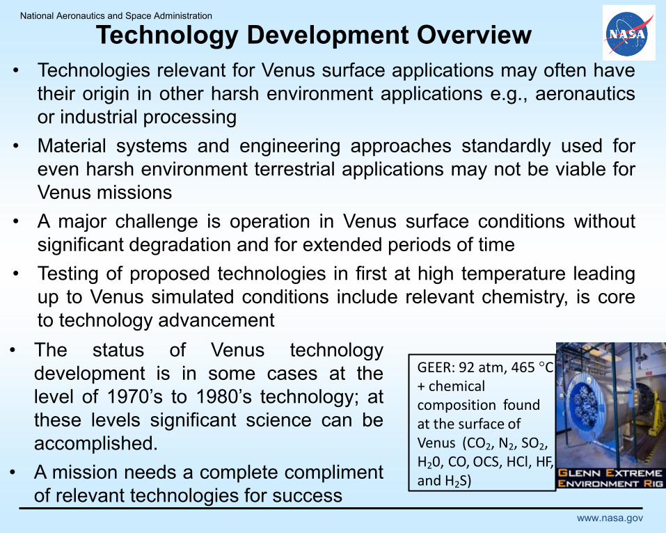
GEER: 92 atm, 465 °C + chemicalcomposition found at the surface ofVenus (CO2, N2, SO2, H20, CO, OCS, HCl, HF, and H2S)
• The status of Venus technology
development is in some cases at the
level of 1970’s to 1980’s technology; at
these levels significant science can be
accomplished.
• A mission needs a complete compliment
of relevant technologies for success
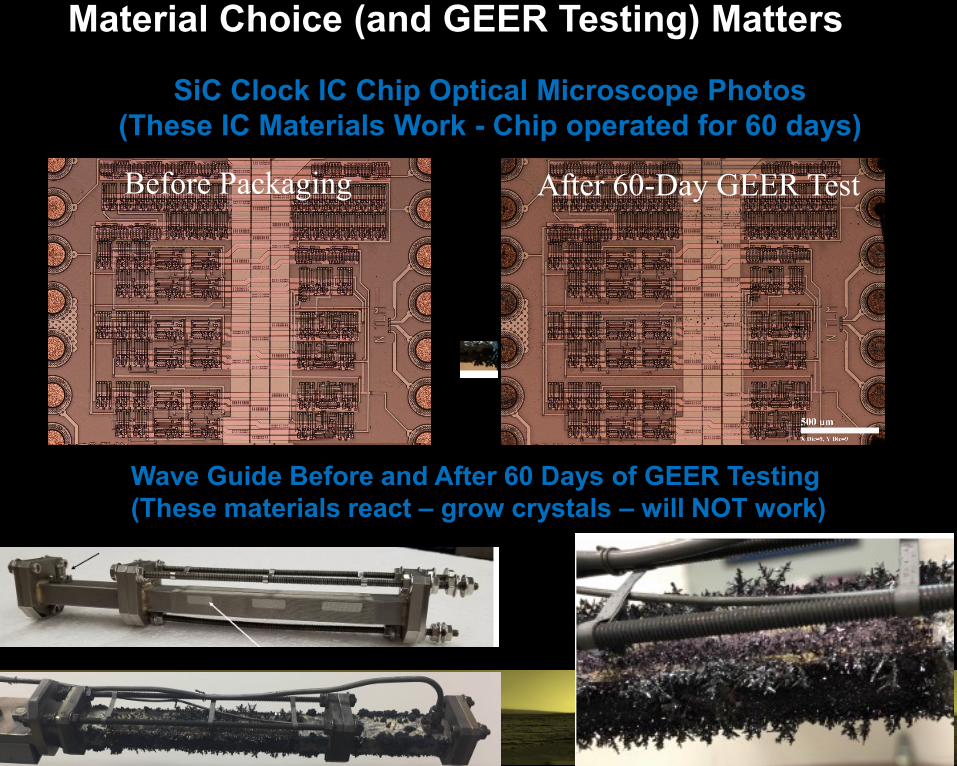
Before Packaging After 60-Day GEER Test
Material Choice (and GEER Testing) Matters
Wave Guide Before and After 60 Days of GEER Testing
(These materials react – grow crystals – will NOT work)
SiC Clock IC Chip Optical Microscope Photos
(These IC Materials Work - Chip operated for 60 days)
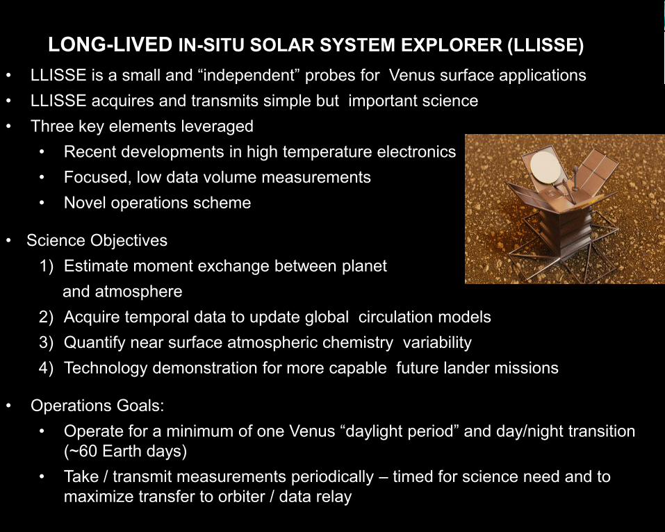
• LLISSE is a small and “independent” probes for Venus surface applications
• LLISSE acquires and transmits simple but important science
• Three key elements leveraged
• Recent developments in high temperature electronics
• Focused, low data volume measurements
• Novel operations scheme
• Science Objectives
1) Estimate moment exchange between planet
and atmosphere
2) Acquire temporal data to update global circulation models
3) Quantify near surface atmospheric chemistry variability
4) Technology demonstration for more capable future lander missions
• Operations Goals:
• Operate for a minimum of one Venus “daylight period” and day/night transition
(~60 Earth days)
• Take / transmit measurements periodically – timed for science need and to
maximize transfer to orbiter / data relay
LONG-LIVED IN-SITU SOLAR SYSTEM EXPLORER (LLISSE)
National Aeronautics and Space Administration
www.nasa.gov
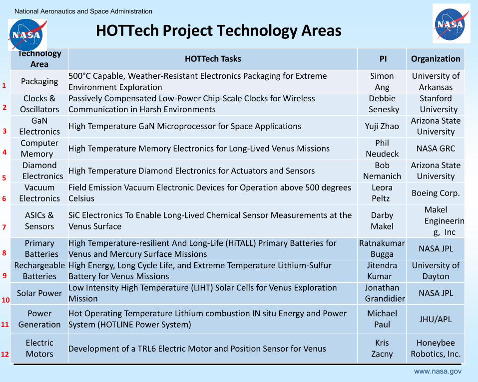
TechnologyArea
HOTTech Tasks PI Organization
Packaging500°C Capable, Weather-Resistant Electronics Packaging for Extreme Environment Exploration
Simon Ang
University of Arkansas
Clocks &Oscillators
Passively Compensated Low-Power Chip-Scale Clocks for WirelessCommunication in Harsh Environments
DebbieSenesky
StanfordUniversity
GaNElectronics
High Temperature GaN Microprocessor for Space Applications Yuji ZhaoArizona State
UniversityComputerMemory
High Temperature Memory Electronics for Long-Lived Venus MissionsPhil
NeudeckNASA GRC
DiamondElectronics
High Temperature Diamond Electronics for Actuators and SensorsBob
NemanichArizona State
UniversityVacuum
ElectronicsField Emission Vacuum Electronic Devices for Operation above 500 degreesCelsius
LeoraPeltz
Boeing Corp.
ASICs & Sensors
SiC Electronics To Enable Long-Lived Chemical Sensor Measurements at the Venus Surface
Darby Makel
MakelEngineerin
g, IncPrimaryBatteries
High Temperature-resilient And Long-Life (HiTALL) Primary Batteries forVenus and Mercury Surface Missions
RatnakumarBugga
NASA JPL
RechargeableBatteries
High Energy, Long Cycle Life, and Extreme Temperature Lithium-SulfurBattery for Venus Missions
JitendraKumar
University ofDayton
Solar PowerLow Intensity High Temperature (LIHT) Solar Cells for Venus ExplorationMission
JonathanGrandidier
NASA JPL
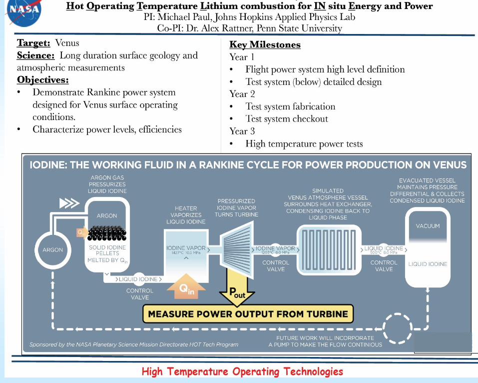
Power Generation
Hot Operating Temperature Lithium combustion IN situ Energy and Power System (HOTLINE Power System)
Michael Paul
JHU/APL
Electric Motors
Development of a TRL6 Electric Motor and Position Sensor for VenusKris
ZacnyHoneybee
Robotics, Inc.
1
2
3
4
5
6
7
8
9
10
11
12
HOTTech Project Technology Areas
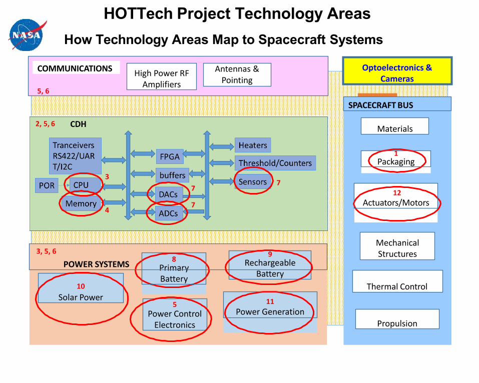
How Technology Areas Map to Spacecraft Systems
SPACECRAFT BUS
Mechanical Structures
Materials
Propulsion
Thermal Control
5, 6
COMMUNICATIONSHigh Power RF
Amplifiers
Antennas & Pointing
1Packaging
8PrimaryBattery
9Rechargeable
Battery
10
Solar Power
77
7
5Power Control
Electronics
4
11
Power Generation
12
Actuators/Motors
3
Optoelectronics & Cameras
2, 5, 6
3, 5, 6
POWER SYSTEMS
HOTTech Project Technology Areas
National Aeronautics and Space Administration
www.nasa.gov
Electronics

National Aeronautics and Space Administration
www.nasa.gov
High Temperature Electronics Advancements
• Unique capabilities have produced the World’s First Microcircuits at
moderate complexity (Medium Level Integration) that have the potential
for long-lived operation at 500˚C
• Circuits contain 10’s to 100’s of JFETs; An order of magnitude beyond a
few JFETs previously demonstrated in the last decade
• Enables a wide range of sensing and control applications at High
Temperatures
In-package signal conditioning for smart sensors
Signal amplification and local processing
Wireless transmission of data
A tool-box of signal conditioning, processing, and communications
circuits are being developed and demonstrated
R&D 100 Award 2018
Cross-sectional illustrations of NASA
Glenn 4H-SiC JFET-R devices with two
levels of interconnect. (a) Simplified
device structure drawing. (b) Scanning
electron micrograph of Generation 10
JFET source and gate region
National Aeronautics and Space Administration
www.nasa.gov
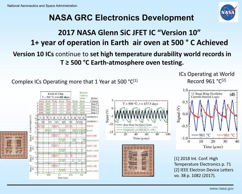
2017 NASA Glenn SiC JFET IC “Version 10”1+ year of operation in Earth air oven at 500 ° C Achieved
Version 10 ICs continue to set high temperature durability world records in T ≥ 500 °C Earth-atmosphere oven testing.
Complex ICs Operating more that 1 Year at 500 °C[1]
ICs Operating at World Record 961 °C[2]
[1] 2018 Int. Conf. High Temperature Electronics p. 71[2] IEEE Electron Device Letters vo. 38 p. 1082 (2017).
NASA GRC Electronics Development
2 or
4
Select
Logic
D Flip-Flops
Inactive
D Flip-Flop
High Frequency Ring Osc.
21-Stage Ring Oscillator
Clock
+ Output Buffers
Active
Address Decoder
Bit
4 X 4 RAM CellArray
Bitline Read/Write Drive Circuitry
with Sense Amplifiers
Output Buffers
National Aeronautics and Space Administration
www.nasa.gov
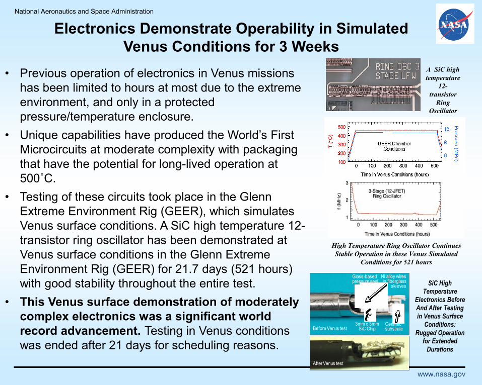
Electronics Demonstrate Operability in Simulated
Venus Conditions for 3 Weeks
• Previous operation of electronics in Venus missions
has been limited to hours at most due to the extreme
environment, and only in a protected
pressure/temperature enclosure.
• Unique capabilities have produced the World’s First
Microcircuits at moderate complexity with packaging
that have the potential for long-lived operation at
500˚C.
• Testing of these circuits took place in the Glenn
Extreme Environment Rig (GEER), which simulates
Venus surface conditions. A SiC high temperature 12-
transistor ring oscillator has been demonstrated at
Venus surface conditions in the Glenn Extreme
Environment Rig (GEER) for 21.7 days (521 hours)
with good stability throughout the entire test.
• This Venus surface demonstration of moderately
complex electronics was a significant world
record advancement. Testing in Venus conditions
was ended after 21 days for scheduling reasons.
A SiC high
temperature
12-
transistor
Ring
Oscillator
High Temperature Ring Oscillator Continues
Stable Operation in these Venus Simulated
Conditions for 521 hours
Glass-basedpressure seal
Ceramicsubstrate
3mm x 3mmSiC Chip
Ni alloy wiresin fiberglass
sleeves
Before Venus test
After Venus test
SiC High
Temperature
Electronics Before
And After Testing
in Venus Surface
Conditions:
Rugged Operation
for Extended
Durations

National Aeronautics and Space Administration
www.nasa.gov
60-Day Venus Environment IC Test (in GEER)1,2
Two IC Version 10 ÷2/÷4 Clock ICs (175 JFETs/chip) successfully operated inGEER Venus surface conditions for 60 days duration.
Before GEER After 60 days GEER
1Neudeck et al., IEEE J. Electron Devices Soc., vol. 1, p. 100 (2018).2Chen et al., Proc. 2018 Int. High Temperature Electronics Conf.
National Aeronautics and Space Administration
www.nasa.gov
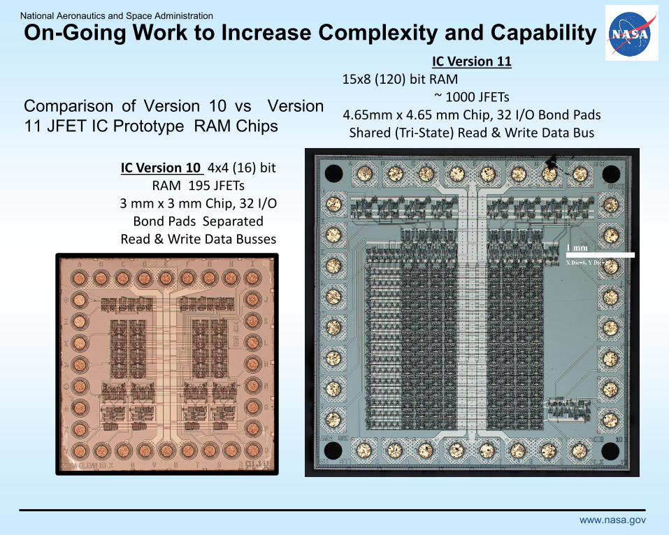
IC Version 1115x8 (120) bit RAM
~ 1000 JFETs4.65mm x 4.65 mm Chip, 32 I/O Bond Pads Shared (Tri-State) Read & Write Data Bus
IC Version 10 4x4 (16) bit RAM 195 JFETs
3 mm x 3 mm Chip, 32 I/O Bond Pads Separated
Read & Write Data Busses
Comparison of Version 10 vs Version
11 JFET IC Prototype RAM Chips
On-Going Work to Increase Complexity and Capability
CoIs: Stephen Goodnick, Franz Koeck, Brianna Eller,
James Lyons/Arizona State University; Srabanti
Chowdhury/UC-Davis;
Hot Operating Temperature Technologies
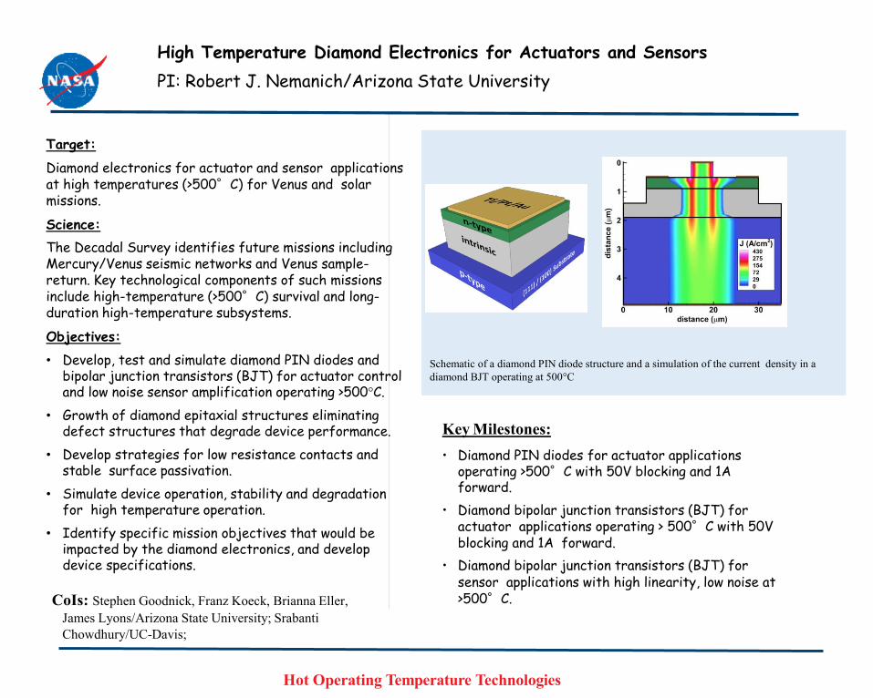
Key Milestones:
• Diamond PIN diodes for actuator applications operating >500°C with 50V blocking and 1A forward.
• Diamond bipolar junction transistors (BJT) for actuator applications operating > 500°C with 50V blocking and 1A forward.
• Diamond bipolar junction transistors (BJT) for sensor applications with high linearity, low noise at >500°C.
Target:
Diamond electronics for actuator and sensor applications at high temperatures (>500°C) for Venus and solar missions.
Science:
The Decadal Survey identifies future missions including Mercury/Venus seismic networks and Venus sample-return. Key technological components of such missions include high-temperature (>500°C) survival and long-duration high-temperature subsystems.
Objectives:
• Develop, test and simulate diamond PIN diodes and bipolar junction transistors (BJT) for actuator control and low noise sensor amplification operating >500°C.
• Growth of diamond epitaxial structures eliminating defect structures that degrade device performance.
• Develop strategies for low resistance contacts and stable surface passivation.
• Simulate device operation, stability and degradation for high temperature operation.
• Identify specific mission objectives that would be impacted by the diamond electronics, and develop device specifications.
Schematic of a diamond PIN diode structure and a simulation of the current density in a
diamond BJT operating at 500°C
High Temperature Diamond Electronics for Actuators and Sensors
PI: Robert J. Nemanich/Arizona State University

National Aeronautics and Space Administration
www.nasa.gov
Packaging
National Aeronautics and Space Administration
www.nasa.gov
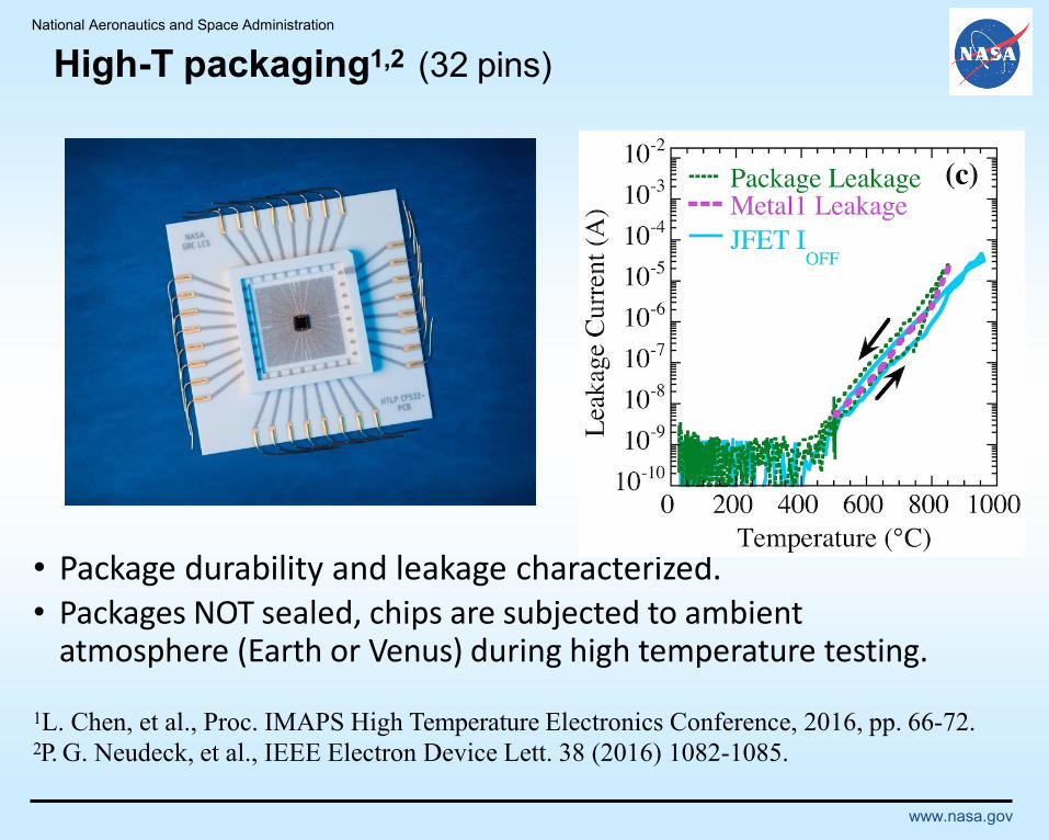
High-T packaging1,2 (32 pins)
• Package durability and leakage characterized.• Packages NOT sealed, chips are subjected to ambient
atmosphere (Earth or Venus) during high temperature testing.
1L. Chen, et al., Proc. IMAPS High Temperature Electronics Conference, 2016, pp. 66-72.2P. G. Neudeck, et al., IEEE Electron Device Lett. 38 (2016) 1082-1085.

Key Milestones:
• High temperature die metallization determination
• Anti-fouling coating selection & evaluation
• Chip integration selection & evaluation
• Substrate integration evaluation
• Package construction and environmental evaluation
• Pre-mechanical chip integration analysis
• GEER testing of packaged components
• Post-mechanical chip integration analysis
Target: Extreme environment package providing flexible I/O and related integration processes.
Science:•Deeper understanding of survival/degradation behavior of die attach, metal interconnect, and housing materials in extreme conditions (500°C, chemically corrosive conditions)
Objectives:
•Leverage existing wide bandgap devices (e.g., SiC and GaN diodes) with high-temperature metallization.
•Develop high-temperature packaging using 500°C capable die attach and metal interconnect technology on ceramic substrates.
•Integrate nanotextured anti-fouling films onto housing surfaces.
•Perform thermal and chemical exposure tests on packaging materials and actual packaged devices using high-temperature furnaces (Stanford) and relevant simulation pressure vessels (NASA and University of Arkansas).
•Analyze experimental data and make specific recommendations to NASA for selection of packaging materials and design architectures to realize HOTTech-relevant systems.
CoIs: Stanford; Dr. Debbie Senesky, ExtremeEnvironment Microsystems Laboratory (Xlab)
H SO2 4
LTCC substrate HTCC-feedthrough
black Al O2 3
SiC diode
Kovar lidResistance
SealingAg sintering
die attach
Base W/Cu
High Temperature Operating Technologies
500°C Capable, Weather-Resistant Electronics Packaging for Extreme Environment Exploration
PI: Simon Ang / Univ. of Arkansas
Nanotextured Anti-fouling Coating
High-temperature Weather- resistant
Electronics Packaging
National Aeronautics and Space Administration
www.nasa.gov
Sensors

National Aeronautics and Space Administration
www.nasa.gov
LLISSE SensorsBroad Array Sensor Technology for Venus Applications
Leveraged From Aeronautics Development
• Active development of harsh environment smart sensors
systems for engine test stand, health management, and
intelligent engine systems
• Demonstration/Application in Multiple
Applications/Commericalized System
Development Approach:
• Miniaturized sensor systems produced by microfabrication
techniques and high temperature compatible materials
• Parallel Development of Multiple Sensor Types
• Pressure
• Temperature
• Wind (3 directions)
• Multiple Chemical Species
• Radiance
• Each sensor has targeted specifications and associated
electronics requirements
Status
• Multiple sensors interface with electronics demonstrated in
Venus Simulated Conditions.
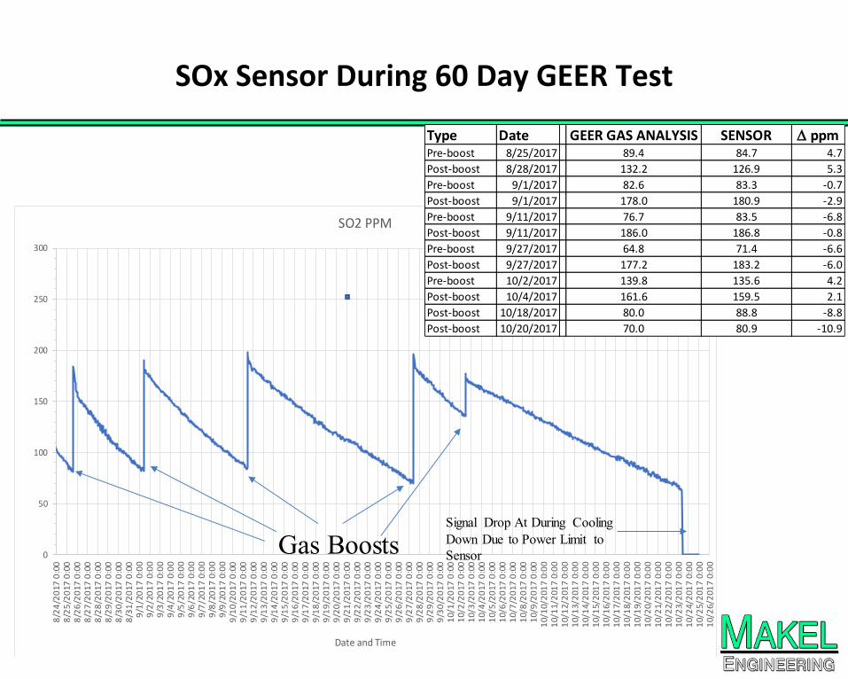
• Demonstration of reliable, responsive SO2 detection for 60
days in Venus simulated conditions
Courtesy of D. Makel, Makel
Engineering, Inc.
Chemical Sensor Array for GEER chamber Simulated Venus Surface testing
High Temperature Pressure Sensor
0
50
100
150
200
250
300
8/2
4/2
017
0:0
08
/25
/20
17 0
:00
8/2
6/2
017
0:0
08
/27
/20
17 0
:00
8/2
8/2
017
0:0
08
/29
/20
17 0
:00
8/3
0/2
017
0:0
08
/31
/20
17 0
:00
9/1
/20
17
0:0
09
/2/2
01
7 0:
00
9/3
/20
17
0:0
09
/4/2
01
7 0:
00
9/5
/20
17
0:0
09
/6/2
01
7 0:
00
9/7
/20
17
0:0
09
/8/2
01
7 0:
00
9/9
/20
17
0:0
09
/10
/20
17 0
:00
9/1
1/2
017
0:0
09
/12
/20
17 0
:00
9/1
3/2
017
0:0
09
/14
/20
17 0
:00
9/1
5/2
017
0:0
09
/16
/20
17 0
:00
9/1
7/2
017
0:0
09
/18
/20
17 0
:00
9/1
9/2
017
0:0
09
/20
/20
17 0
:00
9/2
1/2
017
0:0
09
/22
/20
17 0
:00
9/2
3/2
017
0:0
09
/24
/20
17 0
:00
9/2
5/2
017
0:0
09
/26
/20
17 0
:00
9/2
7/2
017
0:0
09
/28
/20
17 0
:00
9/2
9/2
017
0:0
09
/30
/20
17 0
:00
10/
1/2
017
0:0
01
0/2
/20
17 0
:00
10/
3/2
017
0:0
01
0/4
/20
17 0
:00
10/
5/2
017
0:0
01
0/6
/20
17 0
:00
10/
7/2
017
0:0
01
0/8
/20
17 0
:00
10/
9/2
017
0:0
01
0/1
0/2
017
0:0
01
0/1
1/2
017
0:0
01
0/1
2/2
017
0:0
01
0/1
3/2
017
0:0
01
0/1
4/2
017
0:0
01
0/1
5/2
017
0:0
01
0/1
6/2
017
0:0
01
0/1
7/2
017
0:0
01
0/1
8/2
017
0:0
01
0/1
9/2
017
0:0
01
0/2
0/2
017
0:0
01
0/2
1/2
017
0:0
01
0/2
2/2
017
0:0
01
0/2
3/2
017
0:0
01
0/2
4/2
017
0:0
01
0/2
5/2
017
0:0
01
0/2
6/2
017
0:0
0
Date and Time
SO2 PPM
Gas BoostsSignal Drop At During Cooling
Down Due to Power Limit to
Sensor
SOx Sensor During 60 Day GEER Test
Type Date GEER GAS ANALYSIS SENSOR D ppmPre-boost 8/25/2017 89.4 84.7 4.7
Post-boost 8/28/2017 132.2 126.9 5.3
Pre-boost 9/1/2017 82.6 83.3 -0.7
Post-boost 9/1/2017 178.0 180.9 -2.9
Pre-boost 9/11/2017 76.7 83.5 -6.8
Post-boost 9/11/2017 186.0 186.8 -0.8
Pre-boost 9/27/2017 64.8 71.4 -6.6
Post-boost 9/27/2017 177.2 183.2 -6.0
Pre-boost 10/2/2017 139.8 135.6 4.2
Post-boost 10/4/2017 161.6 159.5 2.1
Post-boost 10/18/2017 80.0 88.8 -8.8
Post-boost 10/20/2017 70.0 80.9 -10.9

Chemical Sensors Progress:
0
500
1000
1500
2000
2500
3000
3500
4000
5/16/2018 0:00 5/17/2018 0:00 5/18/2018 0:00 5/19/2018 0:00 5/20/2018 0:00
Sig
na
l C
ou
nts
(1
2-b
it A
/D
)
GEER 14 Day Test HF Sensor with SiC Amp - raw cnts
HF injections to appoximately 2.5 ppb
Start of Chamber Cooldown
To 150 C
• HF sensor operated with SiC
amplification electronics
throughout May 2018 GEER test
• Internal SiC signal
transduction and amplification
electronics
• External A/D electronics and
data recording
• External sensor temperature
control electronics
• External sensor bias source
• Sensor movement with HF boosts
• No loss of sensor signal
throughout test
SiC Electronics Packaging
SiC Electronics Combined With Chemical Sensor for GEER Testing
Au Paste Reinforcement
Gen I0 Electronics
GEER Test Probe
SiC Diode Chemical Sensor
Au Wire Bonds

Approved for public release
Courtesy: Tom Pike
MEMS seismic event sensor
Sensors images – Courtesy: NASA GRC
Heat Flux sensor - Courtesy: Mike Pauken
Courtesy of D. Makel,
Makel Engineering, Inc.
SAEVe: The Instrument Suite
Rationale for Instruments / Sensors
A) Core science centers around long term
measurements to obtain meteorological and
seismic data over 1 Venus solar day (120
Earth days)
B) This is possible with high temperature, low power,
low data volume instruments / sensors
•Instrument payload supports this constraint
Instrument set includes:
• A 3-axis micro-machined Micro-Electro-Mechanical Systems
(MEMS) seismometer (0.3 kg)
• Meteorological sensor suite (temperature, pressure, wind
speed & direction, solar radiance, atmospheric chemical
species abundances), and solar position sensors (0.7 kg)
• Two COTS Cubesat cameras (0.1 kg each )
• Heat Flux instrument (0.3 kg)

National Aeronautics and Space Administration
www.nasa.gov
Communications
National Aeronautics and Space Administration
www.nasa.gov
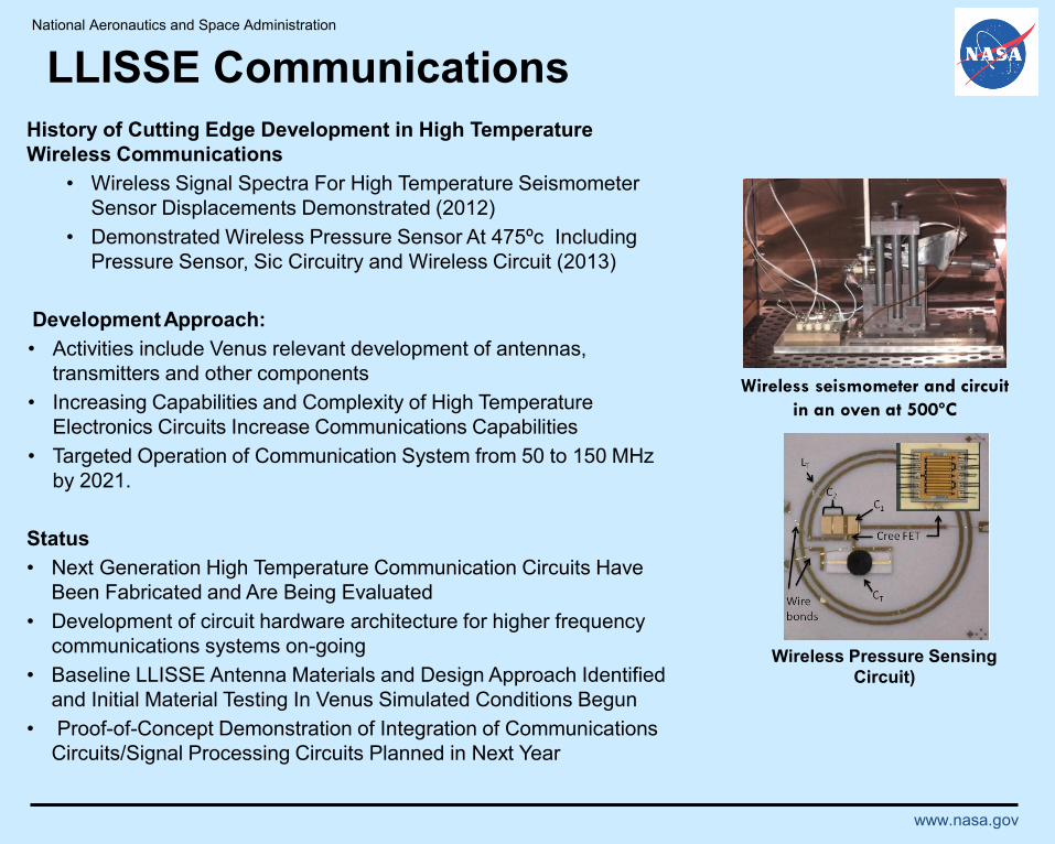
LLISSE Communications
History of Cutting Edge Development in High Temperature
Wireless Communications
• Wireless Signal Spectra For High Temperature Seismometer
Sensor Displacements Demonstrated (2012)
• Demonstrated Wireless Pressure Sensor At 475ºc Including
Pressure Sensor, Sic Circuitry and Wireless Circuit (2013)
DevelopmentApproach:
• Activities include Venus relevant development of antennas,
transmitters and other components
• Increasing Capabilities and Complexity of High Temperature
Electronics Circuits Increase Communications Capabilities
• Targeted Operation of Communication System from 50 to 150 MHz
by 2021.
Status
• Next Generation High Temperature Communication Circuits Have
Been Fabricated and Are Being Evaluated
• Development of circuit hardware architecture for higher frequency
communications systems on-going
• Baseline LLISSE Antenna Materials and Design Approach Identified
and Initial Material Testing In Venus Simulated Conditions Begun
• Proof-of-Concept Demonstration of Integration of Communications
Circuits/Signal Processing Circuits Planned in Next Year
Wireless seismometer and circuit
in an oven at 500ºC
Wireless Pressure Sensing
Circuit)

Passively Compensated Low-Power Chip-Scale Clocks for Wireless Communication in Harsh Environments
PI: Prof. Debbie G. Senesky (Stanford University)
• Year 1:
• Year 2:
1.) Demonstrate resonator with Q above 2,000 2.) Achieve temperature stability below 10 ppm 3.) Perform characterization of discrete resonators and oscillator resonator array
1.) Demonstrate resonator with Q above 5,000 2.) Achieve temperature stability below 1 ppm 3.) Perform high-temperature characterization of oscillator resonator array
Target: Utilize 1000°C capable InAlN/GaN electronic device architectures to mature high-temperature stable clock technology.
Science:
•Increase the duration and scope of many proposed NASA missions to hot planets and bodies (e.g. Venus, Mercury, or Gas Giants).
•Enable stable collection/transmission of scientific data from any probe, lander, explorer, or sensor to be transferred to main spacecraft.
Objectives:
•Adapt existing AlGaN/GaN and AlN micromechanical bulk-mode resonator designs to the InAlN/GaN platform using multi-physics modeling tools.
•Nanofabricate lattice-matched InAlN/GaN micromechanical resonator arrays with high-temperature metallization, passive temperature compensation, and various film doping concentrations to achieve high-temperature operation.
•Perform in-situ high-temperature laboratory characterization (up to 600°C at various pressures) to quantify temperature-dependent frequency response.
Schematic image of an envisioned rover on the hot surface of Venus communicating collected scientific
data with robust radio transmitter chip.
High Temperature Operating Technologies
Key Milestones:
CoIs; Dr. Mina Rais-Zadeh (NASA Jet Propulsion Laboratory
National Aeronautics and Space Administration
www.nasa.gov
Power
National Aeronautics and Space Administration
www.nasa.gov
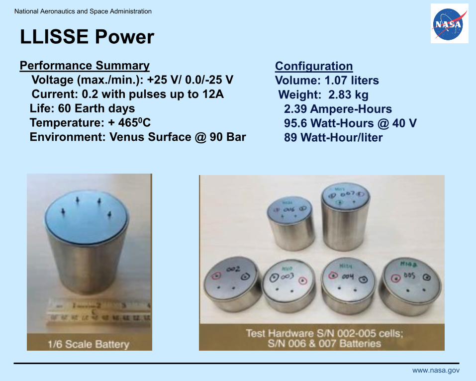
LLISSE Power
Configuration
Volume: 1.07 liters
Weight: 2.83 kg
2.39 Ampere-Hours
95.6 Watt-Hours @ 40 V
89 Watt-Hour/liter
Performance Summary
Voltage (max./min.): +25 V/ 0.0/-25 V
Current: 0.2 with pulses up to 12A
Life: 60 Earth days
Temperature: + 4650C
Environment: Venus Surface @ 90 Bar
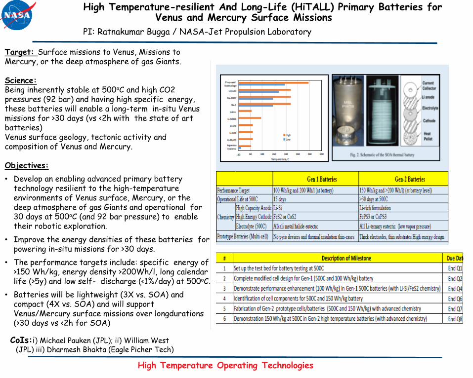
CoIs:i) Michael Pauken (JPL); ii) William West (JPL) iii) Dharmesh Bhakta (Eagle Picher Tech)
High Temperature-resilient And Long-Life (HiTALL) Primary Batteries for Venus and Mercury Surface Missions
PI: Ratnakumar Bugga / NASA-Jet Propulsion Laboratory
High Temperature Operating Technologies
Target: Surface missions to Venus, Missions to Mercury, or the deep atmosphere of gas Giants.
Science:Being inherently stable at 500oC and high CO2 pressures (92 bar) and having high specific energy, these batteries will enable a long-term in-situ Venus missions for >30 days (vs <2h with the state of art batteries)Venus surface geology, tectonic activity and composition of Venus and Mercury.
Objectives:
• Develop an enabling advanced primary battery technology resilient to the high-temperature environments of Venus surface, Mercury, or the deep atmosphere of gas Giants and operational for 30 days at 500oC (and 92 bar pressure) to enable their robotic exploration.
• Improve the energy densities of these batteries for powering in-situ missions for >30 days.
• The performance targets include: specific energy of >150 Wh/kg, energy density >200Wh/l, long calendar life (>5y) and low self- discharge (<1%/day) at 500oC.
• Batteries will be lightweight (3X vs. SOA) and compact (4X vs. SOA) and will support Venus/Mercury surface missions over longdurations(>30 days vs <2h for SOA)
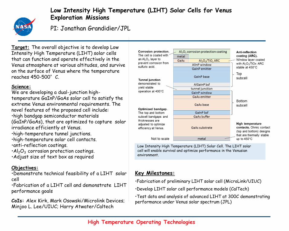
Low Intensity High Temperature (LIHT) Solar Cells for Venus Exploration Missions
PI: Jonathan Grandidier/JPL
Key Milestones:
•Fabrication of preliminary LIHT solar cell (MicroLink/UIUC)
•Develop LIHT solar cell performance models (CalTech)
•Test data and analysis of advanced LIHT at 300C demonstrating performance under Venus solar spectrum (JPL)
Replace this box with figure(s) illustrating and clarifying the concept
Low Intensity High Temperature (LIHT) Solar Cell. The LIHT solar cell will enable survival and optimize performance in the Venusian environment.
Target: The overall objective is to develop Low Intensity High Temperature (LIHT) solar cells that can function and operate effectively in the Venus atmosphere at various altitudes, and survive on the surface of Venus where the temperature reaches 450-500°C.
Science:We are developing a dual-junction high-temperature GaInP/GaAs solar cell to satisfy the extreme Venus environmental requirements. The novel features of the proposed cell include:•high bandgap semiconductor materials (GaInP/GaAs), that are optimized to capture solar irradiance efficiently at Venus.•high-temperature tunnel junctions.•high-temperature solar cell contacts.•anti-reflection coatings.•Al2O3 corrosion protection coatings.•Adjust size of text box as required
Objectives:•Demonstrate technical feasibility of a LIHT solar cell•Fabrication of a LIHT cell and demonstrate LIHT performance goals
CoIs: Alex Kirk, Mark Osowski/Microlink Devices;Minjoo L. Lee/UIUC; Harry Atwater/Caltech
High Temperature Operating Technologies

National Aeronautics and Space Administration
www.nasa.gov
Actuation
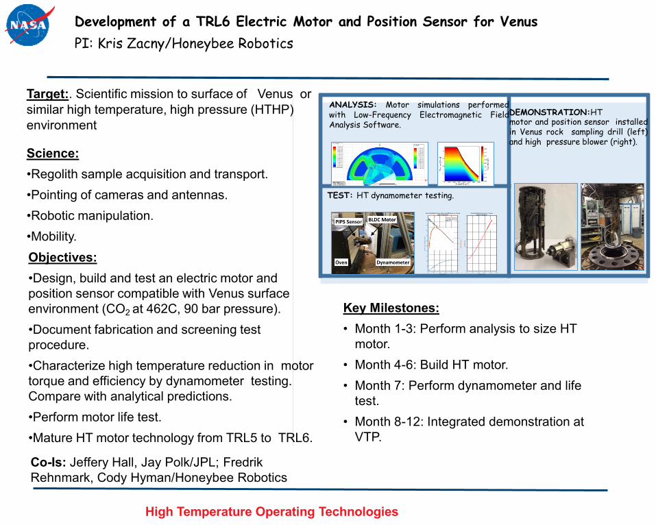
Co-Is: Jeffery Hall, Jay Polk/JPL; Fredrik
Rehnmark, Cody Hyman/Honeybee Robotics
Objectives:
•Design, build and test an electric motor and
position sensor compatible with Venus surface
environment (CO2 at 462C, 90 bar pressure).
•Document fabrication and screening test
procedure.
•Characterize high temperature reduction in motor
torque and efficiency by dynamometer testing.
Compare with analytical predictions.
•Perform motor life test.
•Mature HT motor technology from TRL5 to TRL6.
Key Milestones:
• Month 1-3: Perform analysis to size HT
motor.
• Month 4-6: Build HT motor.
• Month 7: Perform dynamometer and life
test.
• Month 8-12: Integrated demonstration at
VTP.
Target:. Scientific mission to surface of Venus or
similar high temperature, high pressure (HTHP)
environment
Science:
•Regolith sample acquisition and transport.
•Pointing of cameras and antennas.
•Robotic manipulation.
•Mobility.
ANALYSIS: Motor simulations performedwith Low-Frequency Electromagnetic FieldAnalysis Software.
DEMONSTRATION:HTmotor and position sensor installedin Venus rock sampling drill (left)and high pressure blower (right).
TEST: HT dynamometer testing.
High Temperature Operating Technologies
Development of a TRL6 Electric Motor and Position Sensor for Venus
PI: Kris Zacny/Honeybee Robotics
National Aeronautics and Space Administration
www.nasa.gov
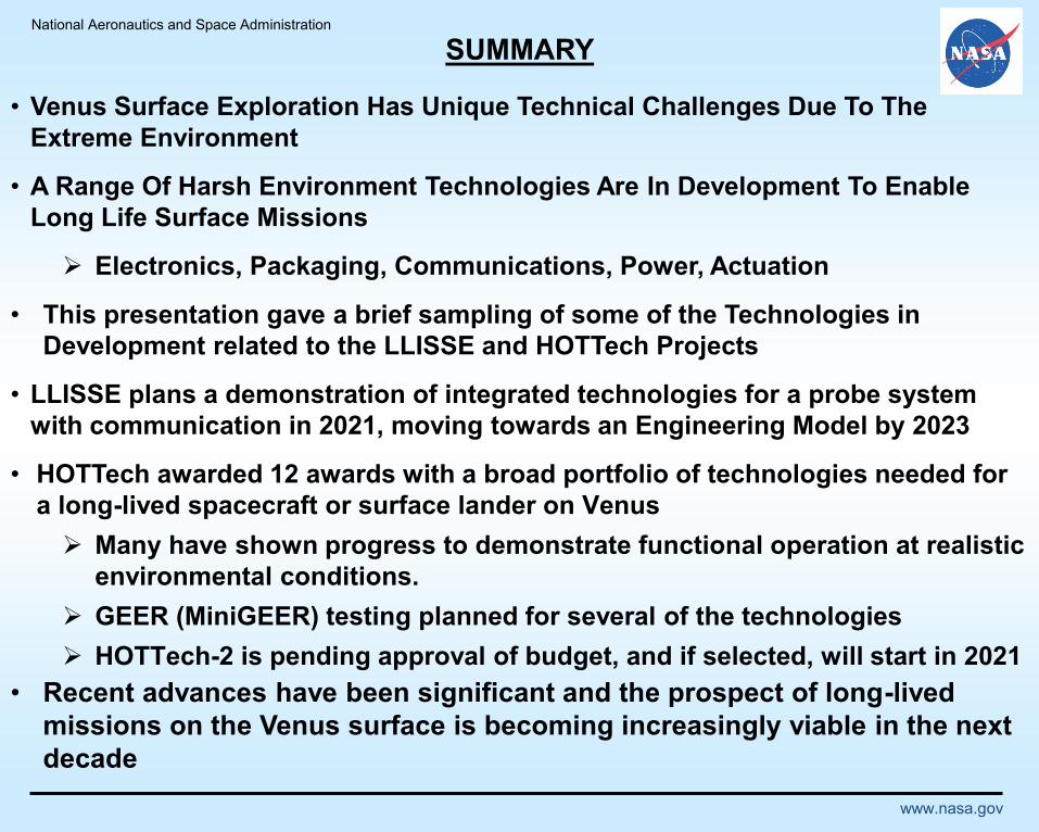
SUMMARY
• Venus Surface Exploration Has Unique Technical Challenges Due To The
Extreme Environment
• A Range Of Harsh Environment Technologies Are In Development To Enable
Long Life Surface Missions
Electronics, Packaging, Communications, Power, Actuation
• This presentation gave a brief sampling of some of the Technologies in
Development related to the LLISSE and HOTTech Projects
• LLISSE plans a demonstration of integrated technologies for a probe system
with communication in 2021, moving towards an Engineering Model by 2023
• HOTTech awarded 12 awards with a broad portfolio of technologies needed for
a long-lived spacecraft or surface lander on Venus
Many have shown progress to demonstrate functional operation at realistic
environmental conditions.
GEER (MiniGEER) testing planned for several of the technologies
HOTTech-2 is pending approval of budget, and if selected, will start in 2021
• Recent advances have been significant and the prospect of long-lived
missions on the Venus surface is becoming increasingly viable in the next
decade

National Aeronautics and Space Administration
www.nasa.gov
Backup
National Aeronautics and Space Administration
www.nasa.gov
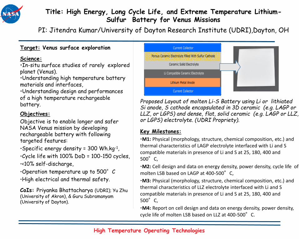
Title: High Energy, Long Cycle Life, and Extreme Temperature Lithium-Sulfur Battery for Venus Missions
PI: Jitendra Kumar/University of Dayton Research Institute (UDRI),Dayton, OH
Target: Venus surface exploration
Science:•In-situ surface studies of rarely explored planet (Venus).•Understanding high temperature battery materials and interfaces,•Understanding design and performances of a high temperature rechargeablebattery.
Objectives:
Objective is to enable longer and safer NASA Venus mission by developing rechargeable battery with following targeted features:
•Specific energy density = 300 Wh.kg-1,
•Cycle life with 100% DoD = 100-150 cycles,
•<10% self-discharge,
•Operation temperature up to 500°C
•High electrical and thermal safety.
CoIs: Priyanka Bhattacharya (UDRI); Yu Zhu (University of Akron), & Guru Subramanyam (University of Dayton).
Proposed Layout of molten Li-S Battery using Li or lithiated Si anode, S cathode encapsulated in 3D ceramic (e.g. LAGP or LLZ, or LGPS) and dense, flat, solid ceramic (e.g. LAGP or LLZ, or LGPS) electrolyte. (UDRI Propriety).
Key Milestones:
•M1: Physical (morphology, structure, chemical composition, etc.) and thermal characteristics of LAGP electrolyte interfaced with Li and S compatible materials in presence of Li and S at 25, 180, 400 and 500°C,
•M2: Cell design and data on energy density, power density, cycle life of
molten LSB based on LAGP at 400-500°C,
•M3: Physical (morphology, structure, chemical composition, etc.) and thermal characteristics of LLZ electrolyte interfaced with Li and S compatible materials in presence of Li and S at 25, 180, 400 and 500°C,
•M4: Report on cell design and data on energy density, power density, cycle life of molten LSB based on LLZ at 400-500°C.
High Temperature Operating Technologies

National Aeronautics and Space Administration
www.nasa.gov
Evolving “Handbook” of What Works in Venus Ambients
Devices Materials Outcome
Electronics Packaging Pb PbS
Al2O3 No reaction
Insulation CaO CaSO3, CaSO4
SiC Electronics Pt PtS; fibers when present as thin film
Pt (in the presence of Au) PtS spheres
Au No reaction, but mobile
Ir No reaction, but mobile
SiC No reaction
SiO2 No reaction
Feedthrough Materials Cu Cu2S crystals
Ni NiS crystals
CuBe Cu2S crystals; Cl found on surface
SiC Pressure Sensor Kovar (Ni-Co-Fe) NiS, FexOy
AlN No reaction
Ag-Cu Braze Segregation into Cu2S and Ag; Ag mobile
GEER Components Inconel 625 (Ni-Cr-Mo-Fe) NiS, CrxOy
304 SS Mirror finish, low corrosion rate
Al foil/Mg dopedMgO on surface, MgF inner layer,
Al bulk no reaction
New Materials Sputtered Aluminum Reacts with HF to form AlF3
Titanium Oxide on surface decreasing into bulk
https://agupubs.onlinelibrary.wiley.com/doi/full/10.1029/2017EA000355