a bio-inspired soft robotic arm kinematic modeling and
TRANSCRIPT
J Bionic Eng 15 (2018) 204–219 Journal of Bionic Engineering DOI: https://doi.org/10.1007/s42235-018-0016-x http://www.springer.com/journal/42235
*Corresponding author: Li Wen E-mail: [email protected]
A Bio-inspired Soft Robotic Arm: Kinematic Modeling and Hydrodynamic Experiments
Zheyuan Gong1, Jiahui Cheng1, Xingyu Chen2, Wenguang Sun1, Xi Fang1, Kainan Hu1,
Zhexin Xie1, Tianmiao Wang1, Li Wen1,3* 1. School of Mechanical Engineering and Automation, Beihang University, Beijing 100191, China
2. State Key Laboratory of Management and Control for Complex Systems, Institute of Automation, Chinese Academy of Sciences, Beijing 100190, China
3. Beijing Advanced Innovation Center for Biomedical Engineering, Beihang University, Beijing 100191, China Abstract
Soft robotics has several promising properties for aquatic applications, such as safe interaction with environments, lightweight, low cost, etc. In this paper, we proposed the kinematic modeling and hydrodynamics experiments of a soft robotic arm with 3D locomotion capacity. We developed a mathematical model that incorporates the angle correction, as well as the open-loop model-based motion control. The model could precisely predict the three-dimensional (3D) movement, and the location error is less than 5.7 mm in different attitudes. Furthermore, we performed the hydrodynamic investigations and simultaneously measured the hydrodynamic forces and the wake flows at different amplitudes (50 mm, 100 mm, 150 mm, 200 mm) and frequencies (0.3 Hz, 0.4 Hz, 0.5 Hz) of the soft arm. Surprisingly, we found that the magnitudes of the hydrodynamic force (<1 N) and the torques (<0.08 N·m) of dynamically moving soft arm were tiny, which leads to negligible inertial effect for the underwater vehicle than those of the traditional rigid underwater manipulator. Finally, we demonstrated underwater picking and placing tasks of the soft manipulator by using a computer program that controls the tip attitude and velocity. This study may inspire future underwater manipulators that have properties of low-inertial, low power cost and can safely interact with the aquatic environments. Keywords: bio-inspired, soft robotic arm, aquatic environment, kinematics, digital particle image velocimetry Copyright © 2018, Jilin University.
1 Introduction
Soft robots can be actuated by variable-length tension cables[1,2], pneumatics or hydraulics for pressurization of channels[3,4], dielectric elastomer[5], and electro-active polymers or shape memory alloy[6–8]. Soft robotics attract growing attention for their unique properties compared with the traditional rigid robotics, such as lightweight, low cost, easy fabrication, and simple to control, etc.[9]. By using design and fabrication methods including deposition manufacturing (SDM)[10], soft lithography[4,11], multi-material 3D printing[12,13], or integrated multiple processes to create the composite materials[14–16], soft robots have many applications including the medical and wearable devices[17], bio-inspired robots[18,19], and industrial manipulation etc.[20,21]. A few studies also embedded smart materials[22] or the biological materials[23] into the body of
bio-inspired soft robots as the actuators. Recently, researchers on soft robotics have begun to focus on the underwater applications. For examples, the SMA actu-ated octopus arms were applied in the underwater lo-comotion and manipulation[24]; the soft hydraulic gripper was implemented for underwater biological sampling[25]; the hydrogel was also used as material to implement the soft actuators for underwater grasping[26]. Recently, a multi-material soft adhesive disc pad inspired by the remora suckerfish was implemented for hitchhiking on different surfaces underwater[12].
Underwater gripping and manipulation is an im-portant area that may require soft robotics technologies. Rigid hydraulic robotic arms were previously applied for underwater collection and manipulation. However, rigid hydraulic robotic arms have colossal mass, and the in-ertia caused by the movement of the rigid arms would induce significant impact on the attitudes control of
Gong et al.: A Bio-inspired Soft Robotic Arm: Kinematic Modeling and Hydrodynamic Experiments
205
underwater vehicles[27–29]. In contrast, soft manipulators have advantages of compliance and lightweight, so they have promising underwater application. To make soft robots controllable, the Piecewise Constant Curvature (PCC) model has been developed[30] and widely used for modeling of the soft robots, such as the bionic handling assistant[31], Air-OCTOR[32], and cable-driven soft manipulators[33], with moderated modification considering the individuality of these prototypes. A few other works established models based on the geometrical information[34] or the real-time finite element method[35], which take the manipulator’s structure and material properties into account. Through deep learning, re-searchers established the neural network model for soft manipulators as well[36,37], therefore to step around the complicated mathematical model and the non-linear material property.
Because of the compliance of soft silicone elas-tomeric manipulators, the manipulator usually rotated an angle along the mounting base due to the manipulator’s weight and loads, leading to a significant mismatch between the model and experiments. To complement this, we describe a mathematic model that incorporates the angle correction that allows the 3D movements to be predicted accurately. We further present the model-based motion control of soft manipulator. In addition, the hy-drodynamics of the soft manipulator in motion has been rarely reported, which is critical for the underwater ap-plication. Therefore, we investigate the hydrodynamic functions of the soft manipulator including forces, and the wake flows at different amplitudes and frequencies of the manipulator in a lab aquatic environment. Finally, we demonstrate underwater picking and placing tasks of the soft manipulator by using a computer program that enables controlling the tip velocity and attitudes of the manipulator.
2 Materials and methods
2.1 Design To realize 3D manipulation tasks, we separate the
functions of soft manipulation as soft arm for 3D loco-motion and soft gripper for grasping. The design, fabri-cation, and grasping performance of soft gripper have been clearly demonstrated in our previous works[20,21]. To achieve the 3D motions in underwater environments,
we design the soft arm as a cylinder to decrease the hydrodynamic resistance when moving in the water flow. The individual chambers and modularized design are applied to the soft arm, which allow the soft arm to reach workspace points in multiple motions with the cooperation of two modular segments. It’s worth to mention that we design the surface of the soft arm as corrugated texture and cover rubber tendons in the groove of corrugated texture to reduce radial ballooning of the chambers when pressurizing. All the tubes for actuating soft arm and soft gripper are embedded and fixed in the central part of the soft arm. Radial ballooning is passive for the precision of manipulation because it fits the assumptions in section 2.2. Although the soft manipulator could be actuated both by air and water, in this paper, we acutated it pneumaticly in all the performed experiments, only showing the concept of an underwater soft robot. More details about the design and fabrication can be found in the supplementary text, Fig. S1. 2.2 Kinematics modeling with angle correction
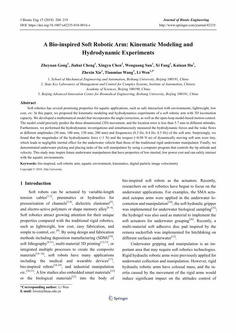
Fig. 1a demonstrates the overview of the soft arm, which consists of two segments, each segment is com-posed of two two-DOF bending sections and two non-deformable death sections that are inevitable due to the fabrication procedure. Although each segment has three individual chambers, we only actuate two of them at one time under consideration of service length. Thus, the whole soft arm has four DOFs with the interaction of six chambers.
Considering the previous work on the modeling of 3D continuum robot[30,38], the modeling can be summed up in two parts (shown in Fig. 1b): (1) the transformation of the attitudes of the arm tip (κi, ϕi, θi) (the subscript i means segment i, the same as below) and chamber length (lij) (lij, the indexes i and j mean segment i chamber j, the same as below); (2) the transformation between chamber length (lij) and the pressure (pij), the direct actuation parameter to the length of chambers (lij). The reason why we choose the chamber length to rep-resent the actuated conditions is to make it easier to clearly describe the soft arm attitudes in 3D space and accomplish measurements, although the curvature rate, swelling volume, and wall thickness all have monotonic

Journal of Bionic Engineering (2018) Vol.15 No.2
206
(b) pi1, pi2, pi3
li1, li2, li3
xi, yi, zi
i, i, θi
finversefforward
(c)
dChamber 2
Chamber 1
Chamber 3x ri
Segment 1
Segment 2
Segment n
General soft arm kinematics General segment kinematics(d) (e)
Q0 y xz
Q2b
Q1b
Qnb
Qb
Li
z
αi
αi
i
x
Qildni
Q(i−1)l
θi
ri
yIndeformabledeath section
Q2l
Bendingsection
Indeformable death section
Bendingsection
(a)Q0
(g)
−10−200 10
X (cm)
200
Y (cm)−10
−20
25
20
Ethernet communicationCamera 1 Camera 2
Serial communication
10
1510
50
20
PC
Mark point
Pneumatic driving device
Soft arm
(f) xz
y
Q1l
Q2l
Q(n−1)l
Qnl
i
Fig. 1 Kinematics modeling. (a) The global view of modeling; (b) the procedure of modeling; (c) the cross-section of the soft arm that shows the 3 actuating chambers and their geometrical relationship; (d) general kinematics model for the soft arm; (e) general kinematics model for a segment; (f) set up for kinematic experiments; (g) workspace simulation of the soft arm. A movie of the soft arm is available in supplementary video S1.
reflections with actuating pressure. By reason of the nonlinear response of soft material and complexity of structures, it’s complicated to figure out in a theoretical way, so we finish this work via experiments and simu-lations (shown in supplementary text, Fig. S2), and we fit formulas for the model-based control recording these results. In order to simplify the model, we make as-sumptions as follow:
(a) The bending section has constant curvature rate, and the indeformable section is totally straight;
(b) The chambers in the same segment are parallel, and the cross sections are equal in the same section.
Like many other continuum robots, the soft robotic
arm and traditional model cannot fit the theoretical curve very well because of the gravity and load. The high ratio of axial and radial length on each series segment is sure to cause a massive torque on mounting or connecting section, no matter on ground or underwater. Thus, rota-tion on the base mount of each segment appears.
To improve control ability on the soft arm, it’s necessary to quantify this rotation under gravity and loads in the kinematic model. The method we created to modify the traditional PCC model is “angle correction”. This model can be applied to other continuum robots to compensate the interference of the gravity and loads on the manipulator.

Gong et al.: A Bio-inspired Soft Robotic Arm: Kinematic Modeling and Hydrodynamic Experiments
207
2.2.1 Forward transformation Previous works[30,38] provide several approach of
solving the forward transformation. Combining these methods with the structures and sizes of our soft arm (shown in Fig. 1c), one can obtain attitudes of the segments tip (κi, ϕi, θi) from the length of the chamber (lij).
( )
2 2 21 2 3 1 2 1 3 2 3
1 2 3
21 ,i i i i i i i i ii
i i i i
l l l l l l l l lr l l l d
κ+ + − − −
= =+ +
(1)
( )1 2 3 1
2 3
2= tan ,
3i i i
ii i
l l ll l
ϕ −⎛ ⎞+ −⎜ ⎟⎜ ⎟−⎝ ⎠
(2)
2 2 21 2 3 1 2 1 3 2 32
= ,3
i i i i i i i i ii
l l l l l l l l ld
θ+ + − − −
(3)
In Eqs. (1)–(3), d represents the radius of soft arm cross-section. li1 represents the outer surface length of chamber 1 in the ith segment. Particularly, we use the surface length mainly considering it is more accessible for measurement.
Furthermore, we can also acquire the coordinate of soft arm tip (x, y, z) from the attitudes (κi, ϕi, θi) we got previously. Mathematically, we consider the soft arm simply consists of constant curvature curves (bending section) and lines (dead structures), shown in Fig. 1d. The coordinate transformation in both curves and lines could be described by homogeneous matrixes shown in
Eq. (4), where R is the rotation matrix, and p is the translation vector.
.0 1⎡ ⎤
= ⎢ ⎥⎣ ⎦
R pΤ (4)
Fig. 1e shows the modeling of a single segment. The orientation angle ϕi represents the rotation around the z-axis, curvature angle θi represents the rotation around the y-axis, and angle αi represents the deviation between the vertical line and a tangent line of soft arm axis due to the gravity and loads, where i indicates the ith segment.
Especially for the first segment, we consider the bending procedure as: first the soft arm rotates around y-axis with angle θ1; second, the soft arm rotates around z-axis with angle ϕ1. Besides, rotation matrix R(−α1) and zero translation are applied for the angle correction after y-axis rotation. Moreover, we need to post-multiply the homogeneous matrix with the rotation matrix R(−ϕ1) and zero translation. The final form of the transforma-tion matrix for the 1st segment is described as Eq. (5).
For second segments, rotation matrix R(−α2) and zero translation need to be pre-multiplied with the ori-entation matrix because the angle αi is always toward gravity. With this method, we can apply angle correction to the second segment in all attitudes. The final form of the transformation matrix for the 2nd segment is described as Eq. (6).
1 1 1 101
1 1 1 1 1 1 1 1
1 1 1
1 1
( ) 0 ( ) 0 ( ) ( ) 00 1 0 1 0 1 0 1
cos sin 0 0 cos 0 sin 0 cos 0 sin cos (1 cos )sin cos 0 0 0 1 0 0 0 1 0 sin (1 c
0 0 1 0 sin 0 cos 00 0 0 1 0 0 0 1
z y y zb
p
rr
ϕ α θ ϕ
ϕ ϕ α α θ θ ϕ θϕ ϕ ϕ
α α
−⎡ ⎤ ⎡ ⎤ ⎡ ⎤ ⎡ ⎤= ⋅ ⋅ ⋅⎢ ⎥ ⎢ ⎥ ⎢ ⎥ ⎢ ⎥⎣ ⎦ ⎣ ⎦ ⎣ ⎦ ⎣ ⎦
− −⎡ ⎤ ⎡ ⎤⎢ ⎥ ⎢ ⎥ −⎢ ⎥ ⎢ ⎥= ⋅ ⋅⎢ ⎥ ⎢ ⎥⎢ ⎥ ⎢ ⎥⎣ ⎦ ⎣ ⎦
R R R RT
1 1
1 1 1
1 1 1
cos sin 0 0os ) sin cos 0 0
sin 0 cos sin 0 0 1 00 0 0 1 0 0 0 1
r
ϕ ϕθ ϕ ϕ
θ θ θ
⎡ ⎤ ⎡ ⎤⎢ ⎥ ⎢ ⎥−⎢ ⎥ ⎢ ⎥⋅⎢ ⎥ ⎢ ⎥⎢ ⎥ ⎢ ⎥⎣ ⎦ ⎣ ⎦
(5)
2 2 2 21l2
2 2 2 2 2 2 2 2
2 2 2
2 2
( ) 0 ( ) 0 ( ) ( ) 00 1 0 1 0 1 0 1
cos 0 sin 0 cos sin 0 0 cos 0 sin cos (1 cos )0 1 0 0 sin cos 0 0 0 1 0 sin (1
sin 0 cos 0 0 0 1 00 0 0 1 0 0 0 1
y z y zb
p
rr
α ϕ θ ϕ
α α ϕ ϕ θ θ ϕ θϕ ϕ ϕ
α α
−⎡ ⎤ ⎡ ⎤ ⎡ ⎤ ⎡ ⎤= ⋅ ⋅ ⋅⎢ ⎥ ⎢ ⎥ ⎢ ⎥ ⎢ ⎥⎣ ⎦ ⎣ ⎦ ⎣ ⎦ ⎣ ⎦
− −⎡ ⎤ ⎡ ⎤⎢ ⎥ ⎢ ⎥ −⎢ ⎥ ⎢ ⎥= ⋅ ⋅⎢ ⎥ ⎢ ⎥⎢ ⎥ ⎢ ⎥⎣ ⎦ ⎣ ⎦
R R R RT
2 2
2 2 2
2 2
cos sin 0 0cos ) sin cos 0 0
sin 0 cos sin 0 0 1 00 0 0 1 0 0 0 1
ir
ϕ ϕθ ϕ ϕ
θ θ θ
⎡ ⎤ ⎡ ⎤⎢ ⎥ ⎢ ⎥−⎢ ⎥ ⎢ ⎥⋅⎢ ⎥ ⎢ ⎥⎢ ⎥ ⎢ ⎥⎣ ⎦ ⎣ ⎦
(6)

Journal of Bionic Engineering (2018) Vol.15 No.2
208
A
ngle
(˚)
Z(m
m)
Fig. 2 Angle correction. (a) The non-tangency angle α defined as the deviation of soft arm center line and vertical line. (b) The non-tangency angle α caused by gravity and loads on the soft arm. (c) Static analysis showing that the angel deformation mainly takes place in the top section. We assume that the centerline is non-stretchable due to the material property. (d) The infinitesimal element to obtain the stretch rate. (e)(f) Comparison between theoretical angles and experimental angles under different pressures.
The dead structure is much more easy to describe
with homogeneous matrix shown in Eq. (7), where dsi is the length of the death section of the ith segment.
ls
1 0 0 00 1 0 0
,0 0 10 0 0 1
ibi
id
⎡ ⎤⎢ ⎥⎢ ⎥=⎢ ⎥⎢ ⎥⎣ ⎦
T (7)
Thus, we can obtain the transformation for the whole segment including bending and dead structures (shown in Eq. (8)), and the transformation for the whole soft arm
(shown in Eq. (9)). Further, we can post-multiply the Eq. (9) with a vector [0 0 0 1] when we want to know the exact coordinate of the tip on the soft arm in the base static coordinate system.
1 1b l= ,i i ib
i i i− − ⋅T T T (8)
0 0 12 1 2= ,⋅T T T (9)
According to the kinematic model, simulation on the workspace of the soft arm can be illustrated as Fig. 2g. We simulate in MATLAB (MATLAB R2015b,
Gong et al.: A Bio-inspired Soft Robotic Arm: Kinematic Modeling and Hydrodynamic Experiments
209
Mathworks, USA) and program the soft arm model to perform 4-DOF motions with interaction on multiple chambers. The results show that the soft arm collects a hollow sphere workspace with the size of approximately 400 mm outer diameter and 280 mm inner diameter, while the soft arm is 200 mm in length and 34 mm in diameter. Moreover, we can collect more space with more segments and bigger size. 2.2.2 Inverse transformation
In the aspect of continuum robots, the attitudes parameters (κi, ϕi, θi) is more suitable to describe mo-tions. So it’s important to find an inverse transformation from attitude parameters (κi, ϕi, θi) to chamber length (lij), which we call specific inverse transformation. As we discussed above that each segment has two DOFs (only two of κi, ϕi, θi are independent), but we need to calcu-late the length of all the three chambers. To solve this function with two input parameters and three output parameters, we summarize a constraint condition as follow. Based on the definition that at most two cham-bers are actuated in a segment at the same time, which means at least one chamber is in initial length, we can solve this problem easily.
From the given inputs (κi, ϕi, θi) of each chamber, we evaluate ϕi to find out the unactuated chamber.
1
2
3
π 5πinitial length; 6 65π 3πinitial length; ,6 2
3π πinitial length; 2π or 02 6
i i
i i
i i i
l
l
l
ϕ
ϕ
ϕ ϕ
⎧ = ≤ <⎪⎪⎪ = ≤ <⎨⎪⎪
= ≤ < ≤ <⎪⎩
(10)
Considering the geometry relationship shown in
Fig. 1c, we can solve the length of other chambers. For
instance, while π 5π6 6iϕ≤ < (li1 is initial length):
1 1 1
2 1 1
3 1 1
πcos( )2
7π 5πcos( ) ; ,6 6 6
11πcos( )6
i i
i i i
i i
L l d
l L d
l L d
θ ϕ
πθ ϕ ϕ
θ ϕ
⎧ = + −⎪⎪⎪ = − − ≤ <⎨⎪⎪
= − −⎪⎩
(11)
The same for 5π 3π6 2iϕ≤ < (shown in Eq. (12))
and 3π 2π2 iϕ≤ < or π0
6iϕ≤ < (shown in Eq. (13)):
2 1 1
1 1 1
3 1 1
7πcos( )6π 5π 3πcos( ) ; ,2 6 2
11πcos( )6
i i
i i i
i i
L l d
l L d
l L d
θ ϕ
θ ϕ ϕ
θ ϕ
⎧ = + −⎪⎪⎪ = − − ≤ <⎨⎪⎪ = − −⎪⎩
(12)
3 1 1
1 1 1
2 1 1
11πcos( )6π 3π πcos( ) ; 2π or 0 ,2 2 67πcos( )6
i i
i i i i
i i
L l d
l L d
l L d
θ ϕ
θ ϕ ϕ ϕ
θ ϕ
⎧ = + −⎪⎪⎪ = − − ≤ < ≤ <⎨⎪⎪ = − −⎪⎩ (13)
Thus, we obtain specific inverse transformation from (κi, ϕi, θi) to (lij). With the help of pressure – length identification (shown in supplementary file Fig. S2), we can transfer from (κi, ϕi, θi) to the driving pressure (pij) to finish the model-based control. 2.2.3 Analysis of the angle correction
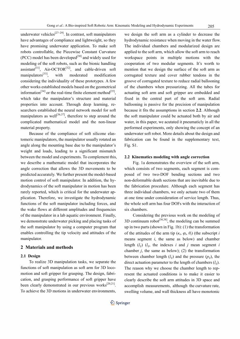
Almost all the continuum robots face the problem of deformation due to the gravity and loads. This deformation appears in different structures and mechanisms. Particularly, for the soft arm made of purely soft material, stress causes larger deformation. When operating, the soft arm chambers are injected with compressed air so that the stiffness of bending sections are much higher than the indeformable sections. That says deformation of the soft arm caused by gravity and loads mainly happens in the base mount of segments. As shown in Fig. 2a, α is defined as the angle between the vertical line and a tangent line of soft arm axis. More-over, the motions and loads have a significant impact on the rotation direction and amplitude of α. As Fig. 2b demonstrated, the weight and load can be transferred to a force F+mg and torque M at the base mount, while M, which causes the deformation of α, is shown as:
2 21 1 ,cM mgx F x y= + + (14)
where xc is the length of barycenter and clamping center

Journal of Bionic Engineering (2018) Vol.15 No.2
210
line, and x1, y1 are the coordinates of segment tip. In order to figure out how different motions and loads impact on α, we choose the indeformable section for static analysis, shown in Fig. 2c. According to material property, the stiffness of PDMS in the center channel is much higher than dragon skin 10. Therefore, we assume that the center of soft arm neither elongates nor buckles, while the stress distribution is liner as the diameter in-creases. At the side of the soft arm where the maximum strain happens, we choose an infinitesimal cubic element, shown in Fig. 2d. Based on the Yeoh model[39] on elastic material, we have the relationship between Green de-formation tensors I1, I2, I3 and principal extension ratios λ1, λ2, λ3:
2 2 21 1 2 3
2 2 2 2 2 22 1 2 2 3 3 1
2 2 23 1 2 3
,I
II
λ λ λλ λ λ λ λ λ
λ λ λ
⎧ = + +⎪ = + +⎨⎪ =⎩
(15)
When considering the deformation condition of the non-inflated silicone structure, we have the following description:
2 3 2=1, =1 / .λ λ λ (16)
The strain energy and stress can be described as:
10 1 01 2C ( 3) C ( 3),W I I= − + − (17)
243
10 01 333 3
1 12C C ,W λσ λ
λ λ λ
⎛ ⎞⎛ ⎞−∂ ⎜ ⎟= = + −⎜ ⎟⎜ ⎟∂ ⎝ ⎠⎝ ⎠ (18)
where the coefficients C10=0.11, C01=0.02 according to the material property. Meanwhile, we can obtain the stress σ from M:
2
2
d .D
DM x Sσ−
= ∫ (19)
S stands for the cross section area of the deformation part.
Therefore:
312 .MD
σ ≈ (20)
According to Eqs. (18) and (19), λ3 can be solved. And we can further solve the elongation distance t from λ3, as well as angle α:
3 = ,L tL
λ + (21)
22= arctan .tD
α ⎛ ⎞⎜ ⎟⎝ ⎠
(22)
To evaluate the model above, we compared the results of the experiment and results calculated by the model; the comparison is demonstrated in Fig. 2e. In particular, Fig. 2f shows the bending line tracked by the camera at a pressure of 70 kPa. 2.3 Experiment setup 2.3.1 Kinematic model based location error
In order to evaluate the capability of the kinematic model, we performed an experiment to quantify the model based location error. The location error is defined as the Euclidean distance of theoretical point and aver-age experimental data points. We applied a stereo cam-eras system to capture the position of marker points on soft arm in different motions under different pressures, and compared this coordinate with model predicted position. Thus, we can obtain the location error of the kinematic model. Fig. 1f shows the experimental setup. The soft arm and stereo cameras are mounted on a 600 mm × 500 mm × 400 mm rigid frame. The soft arm is actuated with our 7-way pneumatic device. We modi-fied the motions and pressures of soft arm using seven proportional valves (ITV0030-2BL, SMC, Japan). Be-sides, the cameras (acA1600-60gc, BASLER, Germany) are fixed at a 63˚ angle ahead and 48 mm distance apart. And we can rebuild the motions and calculate the coor-dinates of marker points in a motion analysis software ProAnalyst (ProAnalyst, Xcitex, USA) from the images captured in different view. The stereo cameras system is carefully characterized in order to control the measuring error. With the help of calibration board (PA-3DP-24, Xcitex, USA) appended to ProAnalyst, we figured out the error in stereo space of camera, which is shown in Table 1. In order to acquire the model predicted coor-dinates, we programmed the kinematic model into MATLAB and input the same parameters. The programs
Table 1 Error of stereo cameras space
Average error(mm)
Standard deviations (mm)
Maximum error (mm)
Minimum error(mm)
0.6381 0.2484 1.1573 0.2891
Gong et al.: A Bio-inspired Soft Robotic Arm: Kinematic Modeling and Hydrodynamic Experiments
211
Without angle correctionAngle correction
Without angle correctionAngle correction
Without angle correctionAngle correction
Actuated
Z(m
m)
−120−150
−60−30
0
−90
−180−210
Unactuated
−3003060X (mm)
−60−240 90 kPa
0 30−30−60−90Y (mm)
−120−150
Without angle correction
Experimental
Angle correction
X (mm)
600−30
3090
150120
−25 0 25 50−50Y (mm)
90 kPa
Z(m
m)
−120
−150
−60
−300
−90
−180−210
−240(e)
Z(m
m)
−120−150
−60−30
0
−90
−180−210−240
−30 03060X (mm)
−6090 kPa
Y (mm)−30 0 30 60 90 150120(c)
(a)30 35 40
Pressure (kPa)45 50 55 60 65 70 75 80 85 90
30 35 40Pressure (kPa)
45 50 55 60 65 70 75 80 85 90
30 35 40Pressure (kPa)
45 50 55 60 65 70 75 80 85 90
5101520253035404550
5
10
15
Erro
r (m
m)
20
25
51015202530354045
Erro
r (m
m)
(b)
(d)
(f)
Erro
r (m
m)
0
0
0
Fig. 3 Location error influenced by pressure in different attitudes. Left panel of (a)(c)(e) shows the actuated conditions, where the red chambers are actuated, and blue chambers are not actuated; right panel of (a)(c)(e) show the bending conditions in contrast between theoretical points (with and without angle correction) and experimental points; (b)(d)(f) show the location error of angle correction model compared with the error without angle correction. have two versions: the one with angle correction and the other without angle correction. The outputs of the pro-gram are the theoretical coordinates. We performed the location error in three representative motions (“S” bending in two actuated conditions and rolling, shown in Figs. 3a, 3c, 3e) with the pressure ranging from 30 kPa to 90 kPa, with 5 kPa increment. Further, we emphasized the significance of angle correction by the comparison of results with angle correction and without angle correc-tion.
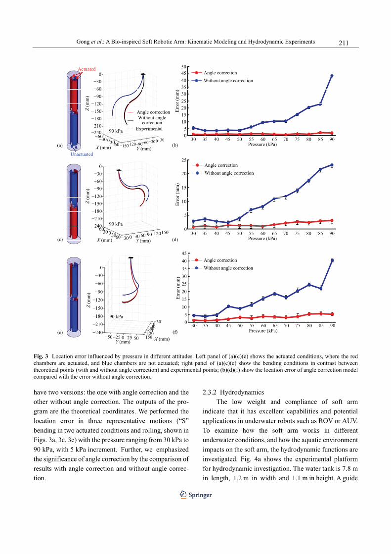
2.3.2 Hydrodynamics The low weight and compliance of soft arm
indicate that it has excellent capabilities and potential applications in underwater robots such as ROV or AUV. To examine how the soft arm works in different underwater conditions, and how the aquatic environment impacts on the soft arm, the hydrodynamic functions are investigated. Fig. 4a shows the experimental platform for hydrodynamic investigation. The water tank is 7.8 m in length, 1.2 m in width and 1.1 m in height. A guide

Journal of Bionic Engineering (2018) Vol.15 No.2
212
(c)
Soft arm to y+ Soft arm to y−
0.1 m·s−1
0.2 m·s−1
0.3 m·s−1
x
y
Vorticity: 0.0−7.5 7.5−15.0 15.0
(a)
x
zy Water tank
Towing systemv
f = 0.3 Hzf = 0.4 Hzf = 0.5 Hz
f = 0.3 Hzf = 0.4 Hzf = 0.5 Hz
A (mm)50 100 150 200
A (mm)50 100 150 200
(b) 1.0
0.8
0.6
0.4
0.2
0.0
Forc
e (N
)To
rque
(N·m
)
0.07
0.090.08
0.060.050.040.030.020.010.00
Fig. 4 (a) Schematic view of the DPIV experimental apparatus; (b) underwater dynamics of the soft arm which is moving in a specific path; (c) DPIV results of soft arm dragged at different speeds. rail, actuated by a 4000-watt AC motor with a travel distance of 7.5 m, with position accuracy of 0.1 mm and a maximum speed of 3 m·s−1, is set above the water tank. A servo towing system is applied to generate precisely controlled towing speed (i.e., the speed of the oncoming flow towards the soft arm can be accurately controlled by towing the model forwards using the servo towing system). To avoid the interference effect of the tank surface and bottom, we mounted and actuated the soft arm at mid-depth of the water tank. To measure the hydrodynamic force, we used a six-axis force transducer (mini-40, ATI Industrial Inc., Canada) which was assembled with the heaving and pitching robotic car-riage connected to the soft arm. The force transducer could measure the lift and thrust forces simultaneously. The force data were collected using a DAQ card (PCI-6284, National Instrument Inc., USA). The high-speed camera was used to record images of particle
movement in the water. The flow was visualized by seeding the water with 10μm-diameter near-neutral buoyant glass beads, which reflected light sheet from a 4 W, 532 nm-wavelength lasers. The laser sheet was projected in the water by a group of mirrors. The 1 mm-thick and 150 mm-wide mid-coronal laser sheet was projected to the x-y plane of the soft arm. Particle images of this plane were recorded with high-speed cameras (SP-5000, JAI Inc., Denmark) at a frequency of 100 Hz. We then obtained the velocity of each point in the calculation region by using commercial software, MicroVec (LiFangTianDi Inc., China) to aid in processing the raw images.
In order to examine how soft arm performs picking and placing tasks in different underwater conditions, soft arm was programmed to move between two given points with different amplitudes A (50 mm, 100 mm, 150 mm, 200 mm) at different frequencies f (0.3 Hz, 0.4 Hz,

Gong et al.: A Bio-inspired Soft Robotic Arm: Kinematic Modeling and Hydrodynamic Experiments
213
0.5 Hz), with the force and torque of the soft arm base mount were recorded. Under the condition of A = 120 mm, f = 0.5 Hz, the soft arm was trailed at different speeds (0 m·s−1, 0.1 m·s−1, 0.2 m·s−1, 0.3 m·s−1). We captured the flow fields via DPIV experiments to examine how the soft arm impacts the flow field when picking and placing in different flow velocities in the water tank. We performed five trials for each experi-ment.
3 Results
3.1 Kinematic model based location error and control Fig. 3 demonstrates the location error versus
chamber pressure in different attitudes. Figs. 3a, 3c, 3e show the three representatives actuated conditions while Figs. 3b, 3d, 3f show the location error associated with the actuation condition on their left. Interestingly, we find that the location error with angle correction is sig-nificantly less than the error without angle correction in all the three motions we test, especially in the high-pressure area (more than 50 kPa). The location error with angle correction stays in the range of 0.8 mm ~ 5.7 mm with the pressure changing from 0 kPa to 90 kPa. Compared with the condition without angle correction, the location error decreases by 96% with the pressure of 90 kPa, 87% with the pressure of 60 kPa and 85% with the pressure of 30 kPa when the soft arm is actuated as Fig. 3a. In both conditions, the location error nearly monotonically increased with the chamber pressure, and the increase has no significant impact on angle correction model within three motions we test. Furthermore, in the contrast of three representative motions, we find that the location error has no signifi-cant changes when the soft arm is in different motions. These results indicate that the angle correction has successfully improved the accuracy the kinematic model and the soft arm is more controllable when doing some picking and placing tasks. More details of the soft arm motion can be found in the supplementary video S1.
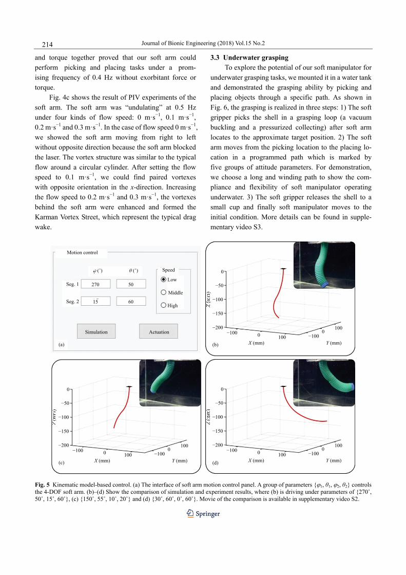
As we have mentioned in the kinematic model, at-titudes {ϕ1, θ1, ϕ2, θ2} were chosen as input parameters. The interface of the control program was shown in Fig. 5a. We programmed the soft arm to make the soft arm move in different attitudes while ϕ1 transfers from
0˚ to 360˚. Figs. 5b, 5c and 5d show the specific positions when the parameters are {270˚, 50˚, 15˚, 60˚}, {150˚, 55˚, 10˚, 20˚} and {30˚, 60˚, 0˚, 60˚}. In the whole movement, we compared the attitudes between simulation and experiment. We found that ex-periment results fit the simulation results well. The lo-cation error is less than 5 mm in the whole procedure. The attitudes and driving phases can all fit those in the simulation. The video of a comparison between simula-tion and experiment can be found in supplementary video S2.
3.2 Hydrodynamics of underwater operation
Fig. 4b indicates how force and torque change with distance and frequency. We conducted five trials for each movement pattern. In each trial, the force and torque were defined as the peak value of raw data during the point-to-point stroke. Notably, when soft arm moved at the frequency of 0.3 Hz, the force increased from 0.178 N to 0.284 N (59.6%) when the moving distance increased. The force of trial at 0.4 Hz remained similar to that of 0.3 Hz. However, the force under the frequency of 0.5 Hz, which dramatically increased to 0.371 N, is 2.08 times stronger than those at 0.3 Hz and 0.4 Hz when the distance was 50 mm. Besides, the growth of force at the frequency of 0.5 Hz, which increased to 0.913 N when the distance was 200 mm, was far faster than those at the other two frequencies. The force increased by 146.1% compared to that of 0.3 Hz (59.6%).
As for the torque, we found that it was significantly larger in the stroke at 0.5 Hz than those at 0.3 Hz and 0.4 Hz. When the frequency was 0.3 Hz, the torque had a slowly minor increment from 0.015 N·m to 0.022 N·m (46.7%). Unlike the curves of forces which were nearly the same under the frequency of 0.4 Hz and 0.3 Hz, the torque of 0.4 Hz showed a burst since the distance varied to 150 mm --- 0.031 N·m, which is higher than that of 0.3 Hz. Once we raised the frequency to 0.5 Hz, the phenomenon of sudden increment appeared again. The torque of 0.5 Hz reached 0.036 N·m when the dis-tance was 50 mm, 2.36 times stronger than those of 0.3 Hz and 0.4 Hz. Enlarging distance to 200 mm, the torque of 0.5 Hz was 0.084 N·m, 3.81 times stronger than those of 0.3 Hz and 0.4 Hz. The results of force
Journal of Bionic Engineering (2018) Vol.15 No.2
214
and torque together proved that our soft arm could perform picking and placing tasks under a prom-ising frequency of 0.4 Hz without exorbitant force or torque.
Fig. 4c shows the result of PIV experiments of the soft arm. The soft arm was “undulating” at 0.5 Hz under four kinds of flow speed: 0 m·s−1, 0.1 m·s−1, 0.2 m·s−1 and 0.3 m·s−1. In the case of flow speed 0 m·s−1, we showed the soft arm moving from right to left without opposite direction because the soft arm blocked the laser. The vortex structure was similar to the typical flow around a circular cylinder. After setting the flow speed to 0.1 m·s−1, we could find paired vortexes with opposite orientation in the x-direction. Increasing the flow speed to 0.2 m·s−1 and 0.3 m·s−1, the vortexes behind the soft arm were enhanced and formed the Karman Vortex Street, which represent the typical drag wake.
3.3 Underwater grasping To explore the potential of our soft manipulator for
underwater grasping tasks, we mounted it in a water tank and demonstrated the grasping ability by picking and placing objects through a specific path. As shown in Fig. 6, the grasping is realized in three steps: 1) The soft gripper picks the shell in a grasping loop (a vacuum buckling and a pressurized collecting) after soft arm locates to the approximate target position. 2) The soft arm moves from the picking location to the placing lo-cation in a programmed path which is marked by five groups of attitude parameters. For demonstration, we choose a long and winding path to show the com-pliance and flexibility of soft manipulator operating underwater. 3) The soft gripper releases the shell to a small cup and finally soft manipulator moves to the initial condition. More details can be found in supple-mentary video S3.
Speed
Low
Middle
High
Motion control
(˚) θ (˚)
50
6015
270Seg. 1
Seg. 2
ActuationSimulation
(b)
(d)
0
−50
−100
−150
−200
X (mm)0−100
100Y (mm)
−1000
100
0
−50
−100
−150
−200
X (mm)0−100
100Y (mm)
−1000
100
(c)
0
−50
−100
−150
−200
X (mm)0−100
100Y (mm)
−1000
100
(a)
Fig. 5 Kinematic model-based control. (a) The interface of soft arm motion control panel. A group of parameters {ϕ1, θ1, ϕ2, θ2} controls the 4-DOF soft arm. (b)–(d) Show the comparison of simulation and experiment results, where (b) is driving under parameters of {270˚, 50˚, 15˚, 60˚}, (c) {150˚, 55˚, 10˚, 20˚} and (d) {30˚, 60˚, 0˚, 60˚}. Movie of the comparison is available in supplementary video S2.

Gong et al.: A Bio-inspired Soft Robotic Arm: Kinematic Modeling and Hydrodynamic Experiments
215
Fig. 6 Underwater grasping performance of soft manipulator. The soft manipulator is able to pick and place underwater objects while tracking a specific path smoothly. The whole grasping process took around 18 s. The motion of the soft manipulator is available in sup-plementary videos S3.
4 Discussion
4.1 Kinematic model of soft manipulator with the angle correction Researchers spent tremendous efforts to enhance
the controllability of the soft robots to achieve precise motions. External sensors and feedback control have become more and more popular ways for the soft arm control. Marchese et al. successfully developed a real-time closed-loop control algorithm that generates realizable curvature trajectories via using a stereo cam-era system[40]. Duriez developed real-time Finite Ele-ment Method (FEM) and showed the potential applica-tion of FEM in the precise control[35]. Giorelli et al.[35] and Jiang et al.[36] considered the soft arm as a black box, and applied neural network and implemented the feed-back strategy. Although there were some previous stud-ies on 3D soft-bodied elastomers especially for ma-nipulation, however, few of them have quantitatively analyzed an open-loop kinematic model[34–37,40].
A simple, useful open-loop model would certainly benefit the motion control of the soft robots. In this study, we proposed a kinematic model with angle correction to solve the gravity/loads impacts on soft robots and quan-titatively analyzed the capability of an open-loop kine-
matic model without any vision or sensory feedback. The experimental results show that, by applying the angle correction, the location errors in all the three mo-tions have been significantly reduced (including the high-pressure region, p>50 kPa). For example, the loca-tion error was decreased by 96% with the pressure of 90 kPa, 87% with the pressure of 60 kPa, and 85% with the pressure of 30 kPa compared with the scenario without the angle correction. These results indicated the significance of the angle correction on kinematic model and precision of the soft arm control. Moreover, the location error remained tiny and didn’t change significantly with the pressures and the attitudes. The errors with angle correction were all less than 5.7 mm with the pressure adjusting to maximum (90 kPa) in different attitudes, which is absolutely in the error tolerance area of the soft gripper (the error tolerance is the deviation of gripper and objects that the gripper could still grasp successfully, which has been demonstrated in our previous papers[20,21]). Therefore, the soft manipulator could achieve grasping in all the actuated pressures and attitudes. With the kinematic model, we successfully achieved precise locomotion in the open-loop control. As for the control method, we not only actuated the soft arm to the destination point

Journal of Bionic Engineering (2018) Vol.15 No.2
216
in a specific attitude but also programmed the path, speed, attitudes for intermediate positions. The experi-ment results are shown in Fig. 5 perfectly coincided with the simulations from the theoretical model, which indicated the potential uses of the soft arm in manipula-tion. A video of the comparison is also available in video S2.
The experiments and data have validated the capa-bility of our model and shown evidence on how the model has effects on the precise locomotion of the soft manipulator. To our knowledge, few types of research quantitatively analyzed an open-loop kinematic model and showed the relatively precise locomotion of soft-bodied elastomers without external sensors and feedback controls. Although with close-loop controls soft arm can achieve better precision and dynamic re-sponse, we emphasize the theoretical model to have a better understanding of how constant curvature works on soft arms, what the controlling principle is for the soft arms. In this work, we proposed a kinematic model with angle correction for the soft continuum robots and performed the precision of model-based control, which may provide a new approach for the control of soft ro-bots. 4.2 Hydrodynamics and underwater manipulation
of the soft robot Rigid robotic arms and grippers for the underwater
manipulations have a huge mass. The inertia caused by the movement of the rigid arms would induce significant impact on the attitudes control of underwater vehicles and slow down the cruising speed as well as the ma-neuverability[27–29,41]. Galloway et al. demonstrated that the squishy, soft robotic fingers could safely interact with the natural, unstructured environments and the fragile organisms[25]. Calisti et al. demonstrated the bending of a bio-inspired soft robotic octopus arm has the grasping capability on flexible objects[38]. Soft robots have advantages of compliance and lightweight and may play an important role in underwater manipulation. However, very few previous studies have investigated the underwater performance of soft robots, and no study has combined the soft arm and the soft gripper for the underwater manipulation tasks. Also the hydrodynamics of soft arm has not been quantified until now.
We performed the hydrodynamics and the picking and placing tasks with the entirely soft manipulator through a specific path for the first time. Compared with the rigid hydraulic manipulators, our soft manipulator has exceptional features of compliance, lightweight and low inertia. We discuss each one of the features as fol-lows: 1) Compliance: our soft arm and gripper are purely soft and have the ability to interact with fragile objects like the shells (shown in Fig. 6 and supplementary video S3). The soft-bodied manipulator also has the natural resistance to huge impacts, which allows it operate in the unstructured environments. 2) Lightweight: the soft manipulator has a mass of 0.251 kg, while with a length of 270 mm. The current prototype is significantly lighter than the traditional rigid hydraulic manipulators that commonly have a mass of tens of kilograms. For exam-ple, a hydraulic manipulator with a length of 499 mm has a total mass of 17.2 kg[27]. 3) Low inertial: Due to the lightweight, the soft manipulator has low inertia property. Soft manipulator with a kinematics of 0.5 Hz (frequency) and 200 mm (amplitude) generates a hydrodynamic force of 0.913 N and torque of 0.084 N·m. In contrast, a 695 mm, 3.25 kg rigid underwater arm generates 50 N force and 15 N·m torque when moving at 0.18 Hz[28]. The locomotion of soft manipulator has negligible iner-tial effect for the underwater vehicle compared with the traditional rigid underwater manipulator. Our results show that the soft manipulator has inherent advantages of compliance, lightweight and has low inertial during the locomotion. We consider the soft arm as a very promising design for a variety of future underwater mission tasks. New fabrication methods and materials may also enhance the performance of the soft arm re-garding multi-materials, variable stiffness, and the inte-gration of soft sensory feedback etc.[42–44].
5 Conclusion
In this paper, we quantitatively analyze the capa-bility of an open-loop kinematic model and test the lo-cation error of open-loop model-based control without vision or sensors feedback. The results will help us achieve a better understanding of how the chambers interact to achieve complex motions and precise location. We demonstrate that the mathematic model that incor-porates the angle correction can precisely predict the 3D

Gong et al.: A Bio-inspired Soft Robotic Arm: Kinematic Modeling and Hydrodynamic Experiments
217
movement, as well as the open-loop model-based mo-tion control. The location error has been considered as an essential indication for the kinematics control. We find that the location error is less than 5.7 mm in dif-ferent attitudes. We investigate the hydrodynamic func-tions of the soft manipulator underwater including forces, and the wake flows when the soft arm stroke at different amplitudes and frequencies. Finally, we demonstrate underwater picking and placing tasks of the soft ma-nipulator by using a computer program that controls the tip velocity and direction. We find that in all amplitudes and frequencies the magnitudes of the hydrodynamic forces are less than 1 N and the torques are less than 0.08 N·m. The small forces lead to negligible inertial effect for the underwater vehicle compared with the traditional rigid underwater manipulators. For future work, non-linear control of the soft manipulator will be investigated. The control will be based on the soft arm’s kinematics model and the sensory feedback, such as the position, angular speed, and external forces, etc.
Acknowledgment
We thank Yufei Hao and Guangyao Huang for their help on this work. This work was supported by the Na-tional Science Foundation support key projects, China, under contract numbers 61633004 and 61333016.
References
[1] Odhner L U, Jentoft L P, Claffee M R, Corson N, Tenzer Y, Ma R R, Buehler M, Kohout R, Howe R D, Dollar A M. A compliant, underactuated hand for robust manipulation. International Journal of Robotics Research, 2014, 33, 736–752.
[2] Yeow C H, Baisch A T, Talbot S G, Walsh C J. Cable-driven finger exercise device with extension return springs for recreating standard therapy exercises. Journal of Medical Devices, 2014, 8, 014502.
[3] Mossadegh B, Polygerinos P, Keplinger C, Wennstedt S, Shepherd R F, Gupta U, Shim J, Bertoldi K, Walsh C J, Whitesides G M. Pneumatic networks for soft robotics that actuate rapidly. Advanced Functional Materials, 2014, 24, 2163–2170.
[4] Shepherd R F, Ilievski F, Choi W, Morina S A, Stokesa A A, Mazzeoa A D, Chena X, Wanga M, Whitesides G M. Mul-
tigait soft robot. Proceedings of the National Academy of Sciences of the United States of America, 2011, 108, 20400.
[5] Girard A, Bigué J P L, O’Brien B M, Gisby T A, Anderson I A, Plante J S´. Soft two-degree-of-freedom dielectric elas-tomer position sensor exhibiting linear behavior. IEEE/ASME Transactions on Mechatronics, 2014, 20, 105–114.
[6] Shen Q, Wang T, Liang J, Wen L. Hydrodynamic per-formance of a biomimetic robotic swimmer actuated by ionic polymer–metal composite. Smart Materials & Struc-tures, 2013, 22, 075035.
[7] Seok S, Onal C D, Cho K J, Wood R J, Rus D, Kim S. Meshworm: A peristaltic soft robot with antagonistic nickel titanium coil actuators. IEEE/ASME Transactions on Mechatronics, 2013, 18, 1485–1497.
[8] Koh J S, Cho K J. Omega-shaped inchworm-inspired Crawling robot with large-index-and-pitch (LIP) SMA spring actuators. IEEE/ASME Transactions on Mechatronics, 2013, 18, 419–429.
[9] Rus D, Tolley M T. Design, fabrication and control of soft robots. Nature, 2015, 521, 467.
[10] Suresh S A, Christensen D L, Hawkes E W, Cutkosky M. Surface and shape deposition manufacturing for the fabrication of a curved surface gripper. Journal of Mechanisms & Robotics, 2015, 7, 021005.
[11] Morin S A, Shepherd R F, Kwok S W, Stokes A A, Nemi-roski A, Whitesides G M. Camouflage and display for soft machines. Science, 2012, 337, 828.
[12] Wang Y, Yang X, Chen Y, Wainwright D K, Kenaley C P, Gong Z, Liu Z, Liu H, Guan J, Wang T, Waver J C, Wood R J, Wen L. A biorobotic adhesive disc for underwater hitchhiking inspired by the remora suckerfish. Science Robotics, 2017, 2, eaan8072.
[13] Bartlett N W, Tolley M T, Overvelde J T, Weaver J C, Mo-sadegh B, Bertoldi K, Whitesides G M, Wood R J. A 3D-printed, functionally graded soft robot powered by combustion. Science, 2015, 349, 161–165.
[14] Cho K J, Koh J S, Kim S, Chu W S, Hong Y, Ahn S H. Review of manufacturing processes for soft biomimetic robots. International Journal of Precision Engineering & Manufacturing, 2009, 10, 171.
[15] Stokes A A, Shepherd R F, Morin S A, Ilievski F, Whitesides G M. A hybrid combining hard and soft robots. Soft Robotics, 2014, 1, 70–74.
[16] Connolly F, Polygerinos P, Walsh C J, Bertoldi K. Me-chanical programming of soft actuators by varying fiber

Journal of Bionic Engineering (2018) Vol.15 No.2
218
angle. Soft Robotics, 2017, 2, 26–32. [17] Park Y L, Chen B R, Pérezarancibia N O, Young D, Stirling
L, Wood R J, Goldfield E C, Nagpal R. Design and control of a bio-inspired soft wearable robotic device for ankle-foot rehabilitation. Bioinspiration & Biomimetics, 2014, 9, 16007–16023.
[18] Calisti M, Giorelli M, Levy G, Mazzolai B, Hochner B, Laschi C, Dario P. An octopus-bioinspired solution to movement and manipulation for soft robots. Bioinspiration & Biomimetics, 2011, 6, 525–531.
[19] Onal C D, Rus D. Autonomous undulatory serpentine lo-comotion utilizing body dynamics of a fluidic soft robot. Bioinspiration & Biomimetics, 2013, 8, 653–668.
[20] Hao Y, Gong Z, Xie Z, Guan S, Yang X, Ren Z, Wang T, Wen L. Universal soft pneumatic robotic gripper with variable effective length. IEEE China Control Conference, Chengdu, China, 2016, 6109–6114.
[21] Hao Y, Wang T, Ren Z, Gong Z, Wang H, Yang X, Guan S, Wen L. Modeling and experiments of a soft robotic gripper in amphibious environments. International Journal of Ad-vanced Robotic Systems, 2017, 14, https://doi.org/ 10.1177/1729881417707148.
[22] Li T, Li G, Liang Y, Cheng T, Dai J, Yang X, Liu B, Zeng Z, Huang Z, Luo Y, Xie T. Fast-moving soft electronic fish. Science Advances, 2017, 3, e1602045.
[23] Park S J, Gazzola M, Park K S, Park S, Santo V D, Blevins E L, Lind J U, Campbell P H, Dauth S, Capulli A K, Pasqualini F S, Ahn S, Cho A, Yuan H, Maoz B M, Vijaykumar R, Choi J W, Deisseroth K, Lauder G V, Mahadevan L, Parker K K. Phototactic guidance of a tissue-engineered soft-robotic ray. Science, 2016, 353, 158–162.
[24] Cianchetti M, Calisti M, Margheri L, Kuba M, Laschi C. Bioinspired locomotion and grasping in water: The soft eight-arm OCTOPUS robot. Bioinspiration & Biomimetics, 2015, 10, 035003.
[25] Galloway K C, Becker K P, Phillips B, Kirby J, Licht S, Tchernov D, Wood R J, Gruber D F. Soft robotic grippers for biological sampling on deep reefs. Soft Robotics, 2016, 3, https://doi.org/10.1089/soro.2015.0019.
[26] Yuk H, Lin S, Ma C, Takaffoli M, Fang N X, Zhao X. Hy-draulic hydrogel actuators and robots optically and sonically camouflaged in water. Nature Communications, 2017, 8, 14230.
[27] Fernandez J J, Prats M, Sanz P J, Garcia J C, Marin R, Robinson M, Ribas D, Ridao P. Grasping for the seabed: Developing a nw uderwater robot arm for shallow-water
intervention. IEEE Robotics & Automation Magazine, 2013, 20, 121–130.
[28] Nakashima M, Takahashi A. Clarification of unsteady fluid forces acting on limbs in swimming using an underwater robot arm. Journal of Fluid Science & Technology, 2012, 7, 114–128.
[29] Ambar R B, Sagara S, Imaike K. Experiment on a dual-arm underwater robot using resolved acceleration control method. Artificial Life & Robotics, 2015, 20, 34–41.
[30] Webster III R J, Jones B A. Design and kinematic mod-eling of constant curvature continuum robots: A review. International Journal of Robotics Research, 2010, 29, 1661–1683.
[31] Rolf M, Steil J J. Constant curvature continuum kinematics as fast approximate model for the bionic handling assistant. IEEE/RSJ International Conference on Intelligent Robots and Systems, Vilamoura, Portugal, 2012, 3440–3446.
[32] Jones B A, Walker I D. Kinematics for multisection con-tinuum robots. IEEE Transactions on Robotics, 2006, 22, 43–55.
[33] Wang H, Chen W, Yu X, Deng T, Wang X, Pfeifer R. Visual servo control of cable-driven soft robotic manipulator. IEEE/RSJ International Conference on Intelligent Robots and Systems, Tokyo, Japan, 2013, 57–62.
[34] Krishnan G. Kinematics of a new class of smart actuators for soft robots based on generalized pneumatic artificial muscles. IEEE/RSJ International Conference on In-telligent Robots and Systems, Chicago, United States, 2014, 587–592.
[35] Duriez C. Control of elastic soft robots based on real-time finite element method. IEEE International Conference on Robotics and Automation, Karlsruhe, Germany, 2013, 3982–3987.
[36] Giorelli M, Renda F, Calisti M, Arienti A, Ferri G, Laschi C. Neural network and Jacobian method for solving the inverse statics of a cable-driven soft arm with nonconstant curvature. IEEE Transactions on Robotics, 2015, 31, 823–834.
[37] Jiang H, Wang Z, Liu X, Chen X, Jin Y, You X, Chen X. A two-level approach for solving the inverse kinematics of an extensible soft arm considering viscoelastic behavior. IEEE International Conference on Robotics and Automation, Singapore, 2017.
[38] Gong Z, Xie Z, Yang X, Wang T, Wen L. Design, fabrication and kinematic modeling of a 3D-motion soft robotic arm. IEEE International Conference on Robotics and Biomimet-ics, Qingdao, China, 2016, 509–514.

Gong et al.: A Bio-inspired Soft Robotic Arm: Kinematic Modeling and Hydrodynamic Experiments
219
[39] Yeoh O H. Some forms of the strain energy function for rubber. Rubber Chemistry & Technology, 2012, 66, 754–771.
[40] Marchese A D, Rus D. Design, kinematics, and control of a soft spatial fluidic elastomer manipulator. International Journal of Robotics Research, 2015, 35, 840–869.
[41] Escande C, Chettibi T, Merzouki R, Coelen V, Pathak P M. Kinematic calibration of a multisection bionic manipulator. IEEE/ASME Transactions on Mechatronics, 2015, 20, 663–674.
[42] Hao Y, Wang T, Xie Z, Sun W, Liu Z, Fang X, Yang M and
Wen L. A eutectic-alloy-infused soft actuator with sensing, tunable degrees of freedom, and stiffness properties. Jour-nal of Micromechanics and Microengineering, 2018, 28 024004.
[43] Wen L, Weaver J C, Lauder G V. Biomimetic shark skin: Design, fabrication and hydrodynamic function. The Journal of Experimental Biology, 2014, 217, 1656–1666.
[44] Wen L, Weaver J C, Thornycroft P M, Lauder G V. Hydro-dynamic function of biomimetic shark skin: Effect of denti-cle pattern and spacing. Bioinspiration Biomimetics, 2015, 10, 066010.