a benchmark study of procedures for analysis of axial ... · obtained by the simplified analyses...
TRANSCRIPT
General rights Copyright and moral rights for the publications made accessible in the public portal are retained by the authors and/or other copyright owners and it is a condition of accessing publications that users recognise and abide by the legal requirements associated with these rights.
Users may download and print one copy of any publication from the public portal for the purpose of private study or research.
You may not further distribute the material or use it for any profit-making activity or commercial gain
You may freely distribute the URL identifying the publication in the public portal If you believe that this document breaches copyright please contact us providing details, and we will remove access to the work immediately and investigate your claim.
Downloaded from orbit.dtu.dk on: May 17, 2020
A benchmark study of procedures for analysis of axial crushing of bulbous bows
Yamada, Yasuhira; Pedersen, Preben Terndrup
Published in:Marine Structures
Link to article, DOI:10.1016/j.marstruc.2007.10.001
Publication date:2008
Document VersionEarly version, also known as pre-print
Link back to DTU Orbit
Citation (APA):Yamada, Y., & Pedersen, P. T. (2008). A benchmark study of procedures for analysis of axial crushing ofbulbous bows. Marine Structures, 21(2-3), 257-293. https://doi.org/10.1016/j.marstruc.2007.10.001

1/38
A Benchmark Study of Procedures for Analysis of Axial
Crushing of Bulbous Bows
Yasuhira Yamadaa,b, ∗ and Preben Terndrup Pedersena
aDepartment of Mechanical Engineering, Technical University of Denmark, Building 403, DK-2800 Kgs., Lyngby, Denmark
bNational Maritime Research Institute, 6-38-1, Shinkawa, Mitaka-shi, Tokyo, Japan
Abstract Simplified methods to estimate mean axial crushing forces of plated structures are reviewed and applied to a series of experimental results for axial crushing of large-scale bulbous bow models. Methods based on intersection unit elements such as L, T and X type elements as well as methods based on plate unit elements are employed in the analyses. The crushing forces and the total absorbed energy obtained by the simplified analyses are compared with those obtained from large scale bulbous bow experiments. The accuracy and the applicability of these methods are discussed in detail. KEY WORDS: ship collision, simplified method, axial crushing. effective crushing distance, bulbous bow, buffer bow, crashworthiness 1. Introduction In order to reduce the risk of oil spill from struck oil tankers a buffer bow concept was proposed by the Association for Structural Improvement of Shipbuilding Industry (ASIS) [1] and its effectiveness was analytically and empirically investigated for several specific collision scenarios by Kitamura [2], and Endo & Yamada [3-6]. To apply the buffer bow concept it is important to be able to estimate the crushing forces and energy absorption of buffer bow structures as well as of conventional bow structures. In general the crashworthiness of ship structures against collision is one of the important matters relating to the safety of ships and crews on board. To evaluate the crashworthiness of ship structures the finite element analysis (FEA) is a powerful numerical tool. To perform a large-scale FEA, however, is still time-consuming due to the effort required when creating the finite element model as well as the numerical calculation itself. Therefore, there is a need for simplified methods to calculate the crashworthiness of ships in the early stages of the design, in the rule making process as well as for risk
∗ Corresponding author. Y Yamada Tel.: +45-4525-1372; Fax: +45-4588-4325. E-mail address: [email protected]
2/38
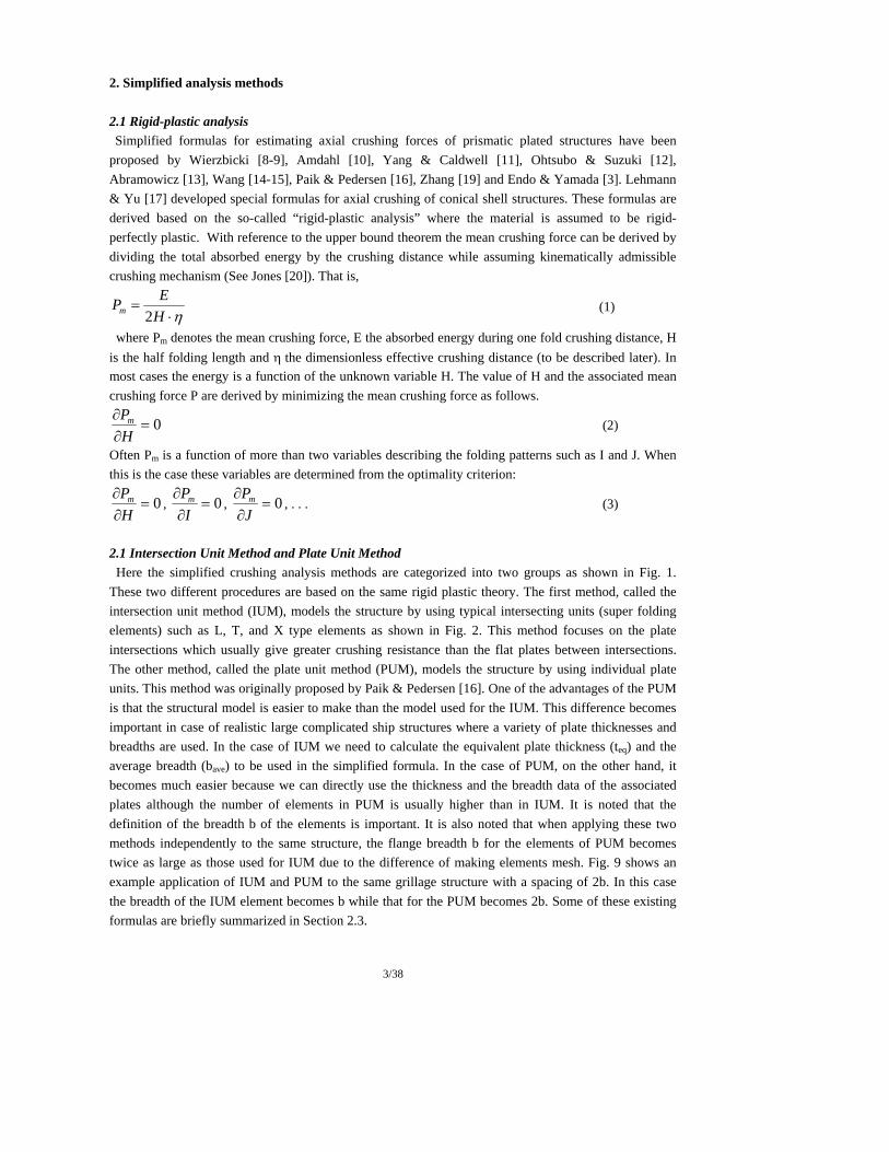
and reliability analyses. A variety of simplified formulas have been proposed in order to estimate the mean crushing forces of plated structures such as ship bows. Although these formulas are based on the same rigid - plastic material modelling procedures they are in reality different due to different assumed folding mechanisms. The purpose of this paper is a review of existing simplified analysis methods and to find the most suitable and accurate formula for estimating the crushing behaviour of bulbous bows.
The International Ship and Offshore Structures Congress (ISSC) specialist panels on structural design
against collision and grounding has continuously reviewed the most recent literature and its applicability for predicting the crushing and cutting damage of ships in collision and groundings [7].
Simplified formulas for estimating axial crushing forces of prismatic plated structures have been proposed by Wierzbicki [8-9], Amdahl [10], Yang & Caldwell [11], Ohtsubo & Suzuki [12], Abramowicz [13], Wang et al [14-15], and Paik and Pedersen [16]. Lehman & Yu [17] derived analytical formulae for estimating the axial crushing strength of a conical shell modelling the outer part of bulbous bow structures. Later Paik & Wierzbicki [18] performed a comprehensive benchmark study on the application of simplified methods to a series of quasi-static crushing tests using longitudinally, transversely or orthogonally stiffened square tubes. The analytical results by Amdahl [10], Wierzbicki & Abramowicz [9], Abramowicz, Ohtsubo & Suzuki [12] and Paik & Pedersen [16] were compared with the experimental results. It was concluded in this study that the methods by Wierzbicki & Abramowicz [9] and Paik & Pedersen [16] give relatively good estimations as compared with other methods for axially compressed thin-walled prismatic structures with quite simple geometries. More recently, Zhang [19] and Endo & Yamada [3] developed a new set of simplified methods. The above mentioned theoretical procedures for estimation of the crushing behaviour of prismatic structures are based on experimental validation using thin lightly stiffened structures measuring 2 – 4 mm. However these structures have much lower thicknesses and have much simpler geometries than found in practical bulbous bow structures on ships. It is anticipated that in more heavily stiffened structures the stiffeners and/or webs make earlier plate-to-plate contact and will prevent the deformation and folding of the outer shell. This can be expected to result in larger crushing resistance. Another source of concern is the assumption of prismatic structures. The configuration of practical bulbous bows differs from the exact prismatic shape. In order to clarify the crushing mechanism of bulbous bow structures and to obtain realistic
experimental data the first author has conducted a series of axial crushing tests using large-scale bulbous bow models, where the model is almost half scale of actual very large crude oil carriers (VLCC). These models are also representative for actual bulbous bows of ships of about 500 tons. In the present paper theories based on intersection elements such as L, T and X type elements as well as theories based on plate unit elements are employed and applied to the axial crushing of these bulbous bow models. The results obtained by a number of different simplified analyses procedures are compared with those observed in the experiments and the applicability and accuracy of the simplified procedures are discussed in detail.
3/38
2. Simplified analysis methods 2.1 Rigid-plastic analysis Simplified formulas for estimating axial crushing forces of prismatic plated structures have been
proposed by Wierzbicki [8-9], Amdahl [10], Yang & Caldwell [11], Ohtsubo & Suzuki [12], Abramowicz [13], Wang [14-15], Paik & Pedersen [16], Zhang [19] and Endo & Yamada [3]. Lehmann & Yu [17] developed special formulas for axial crushing of conical shell structures. These formulas are derived based on the so-called “rigid-plastic analysis” where the material is assumed to be rigid-perfectly plastic. With reference to the upper bound theorem the mean crushing force can be derived by dividing the total absorbed energy by the crushing distance while assuming kinematically admissible crushing mechanism (See Jones [20]). That is,
η⋅=
HEPm 2
(1)
where Pm denotes the mean crushing force, E the absorbed energy during one fold crushing distance, H is the half folding length and η the dimensionless effective crushing distance (to be described later). In most cases the energy is a function of the unknown variable H. The value of H and the associated mean crushing force P are derived by minimizing the mean crushing force as follows.
0=∂∂
HPm (2)
Often Pm is a function of more than two variables describing the folding patterns such as I and J. When this is the case these variables are determined from the optimality criterion:
0=∂∂
HPm , 0=
∂∂
IPm , 0=
∂∂
JPm , . . . (3)
2.1 Intersection Unit Method and Plate Unit Method Here the simplified crushing analysis methods are categorized into two groups as shown in Fig. 1. These two different procedures are based on the same rigid plastic theory. The first method, called the intersection unit method (IUM), models the structure by using typical intersecting units (super folding elements) such as L, T, and X type elements as shown in Fig. 2. This method focuses on the plate intersections which usually give greater crushing resistance than the flat plates between intersections. The other method, called the plate unit method (PUM), models the structure by using individual plate units. This method was originally proposed by Paik & Pedersen [16]. One of the advantages of the PUM is that the structural model is easier to make than the model used for the IUM. This difference becomes important in case of realistic large complicated ship structures where a variety of plate thicknesses and breadths are used. In the case of IUM we need to calculate the equivalent plate thickness (teq) and the average breadth (bave) to be used in the simplified formula. In the case of PUM, on the other hand, it becomes much easier because we can directly use the thickness and the breadth data of the associated plates although the number of elements in PUM is usually higher than in IUM. It is noted that the definition of the breadth b of the elements is important. It is also noted that when applying these two methods independently to the same structure, the flange breadth b for the elements of PUM becomes twice as large as those used for IUM due to the difference of making elements mesh. Fig. 9 shows an example application of IUM and PUM to the same grillage structure with a spacing of 2b. In this case the breadth of the IUM element becomes b while that for the PUM becomes 2b. Some of these existing formulas are briefly summarized in Section 2.3.

4/38
Modelling Technique
Plate Unit Method (PUM)
(Plate Unit)
Intersection Unit Method (IUM)
(L, T and X Element)
Fig. 1. Two groups of simplified methods.
T-type X-type
P P
L-type
P
b b b
b b b
b b b
t t t t t t
Fig. 2. Intersection Unit Elements. L-, T- and X- type elements.
Plate Unit Element
P
b3
b1
t2 t3
b2t1
Fig. 3. Plate Unit Elements 2.2 Effective crushing distance It is well known that a plated steel structure does not get completely squashed to zero height because
of the finite folding radius and plate thickness. This means that only a limited part (60% – 85%) of the original length in load direction is collapse-able. The effective crushing distance, δeff, is widely used in developing simplified formula. A dimensionless effective crushing distance η which is obtained by dividing δeff by the original length of the structure is also widely used. So far an empirical value of η=2/3 has been used by many researchers. Recently, based on a series of crushing tests, Paik et al [21] and Paik & Wierzbicki [18] proposed η=0.73 for unstiffened structures and derived an empirical formula which gives lower η values for stiffened plates. These values are functions of the slenderness ratio β (=b/t) of the structural elements. Therefore, we need to use different values of η as function of the amount of stiffening and the slenderness ratios. In the following review of formulas for crushing strength, the dimensionless effective crushing distance is replaced by the symbol η instead of using the proposed original values in order to make each formula more general.

5/38
2.3 Review of existing methods In the following existing methods are briefly reviewed. In the formulas we have introduced:
4
20
0tM σ
= (4)
20uy σσ
σ+
= (5)
where M0 is the fully plastic plate bending moment for unit breadth, σ0 the flow stress, σy the yield stress, and σu the ultimate material strength. Moreover, σm and β denote the mean crushing stress and the plate slenderness ratio (=b/t), respectively. (1)Amdahl (1983) [10] Amdahl developed the following unified closed formula for the mean axial crushing force (Pm) of plated structures:
( )
32
41
2
32
2
0 31.031.0
27.187.042.2⎪⎭
⎪⎬
⎫
⎪⎩
⎪⎨
⎧
⎥⎦
⎤⎢⎣
⎡+
++⋅⎟⎟
⎠
⎞⎜⎜⎝
⎛⋅=
tNNA
NNN
AtN
APTXLT
TXLTm σ (6)
here σ0, denotes the flow stress, A is the sectional area, , NX the number of X type elements, NT the number of T elements and NLT the number of L and T elements. Good agreements were achieved between theoretical results and extensive experiments where a series of bow models were collapsed axially in quasi-static condition. (2)Yang & Caldwell (1988) [11] Based on methods derived by Wierzbicki [8-9] and Amdahl [10], Yang & Caldwell (1988) developed
simplified formulas for crushing forces for L-, T- and X- type elements assuming four types of basic deformation mechanisms assuming η=2/3. During the process of re-derivation of Yang and Caldwell’s results the present authors obtained slightly different crushing formulas for some element types. Most of the formulas described here are identical to the Yang & Caldwell’s formulas, but Eqs. (52), (54), (56), and (57) in the appendix are slightly different from Yang & Caldwell’s expressions. Some constant terms seem to be ignored in the Yang & Caldwell’s formulas probably based on the assumption that the effect of these terms on the entire strength is small if the slenderness ratio is large enough. However, the validity of this assumption largely depends on the structural arrangement. Therefore, in the present paper we include these constant terms. Moreover, a study of the derivations shows that the radius of the toroidal shell element, r, must have been assumed to be four times the plate thickness in order to achieve the published closed formulas. That is r=4t. This assumption seems reasonable if the slenderness ratio of the plate is around 50. However, it is noted that this assumption does not always fulfil the minimization of the crushing force. The formulas derived by the present authors and presented in the appendix are expressed in the same form as in Yang & Caldwell (1988), i.e. the mean crushing forces are normalized by the fully plastic bending moment (M0). The mean crushing stresses normalized by the flow stress are given below using H and/or r values
which minimize the absorbed energy according to Eqs. (2) and (3):

6/38
(i) Mode 1 for L type element (Mode L1)
⎟⎟⎠
⎞⎜⎜⎝
⎛= 3/2
0
52068.11βησ
σ m (7)
3 2549.1 tbH = , 3 28771.0 btr = (8)
(ii) Mode 1 for T type element (Mode T1)
⎟⎟⎠
⎞⎜⎜⎝
⎛= 3/2
0
1605.11βησ
σ m (9)
3 2030.2 tbH = (10)
(iii) Mode 2 for T type element (Mode T2)
⎟⎟⎠
⎞⎜⎜⎝
⎛+=
ββησσ 1309.0860512.01
5.00
m (11)
btH 825.1= (12) (iv) Mode 3 for T type element (Mode T3)
⎟⎟⎠
⎞⎜⎜⎝
⎛+=
ββησσ 67197.1943783.01
5.00
m (13)
btH 664.1= (14) (v) Mode 4 for T type element (Mode T4)
⎟⎟⎠
⎞⎜⎜⎝
⎛+=
ββησσ 19635.042349.11
5.00
m (15)
btH 103.1= (16) (vi) Mode 1 for X type element (Mode X1)
⎟⎟⎠
⎞⎜⎜⎝
⎛+=
ββησσ 25397.181734.01
5.00
m (17)
btH 922.1= (18) (vii) Mode 2 for X type element (Mode X2)
⎟⎟⎠
⎞⎜⎜⎝
⎛+=
ββησσ 25.025331.11
5.00
m (19)
btH 253.1= (20) (iix) Mode 3 for X type element (Mode X3)
⎟⎟⎠
⎞⎜⎜⎝
⎛+=
ββησσ 19635.042349.11
5.00
m (21)
btH 103.1= (22)

7/38
Yang & Caldwell (1988)
0
0.2
0.4
0.6
0 50 100 150
Slenderness ratio (β )
Dim
ensi
onle
ss st
ress
( σm/ σ
0 )
(a)L1
(b)T1
(c)T2
(d)T3
(e)T4
(f)X1
(g)X2
(h)X3
σ
(a)Mode L1 Eq.(7), (b) Mode T1 Eq.(9), (c) Mode T2 Eq.(11),
(d) Mode T3 Eq.(13), (e) Mode T4 Eq.(15) (f) Mode X1 Eq.(17), (g) Mode X2 Eq.(19), (h) Mode X3 Eq.(21)
Fig. 4. Comparison of dimensionless mean crushing stresses vs. slenderness ratio for the L, T and X type elements developed by Yang & Caldwell (1988). η=2/3 is applied. Dimensionless crushing stresses obtained by the modified Yang & Caldwell formulas for L, T and X type elements are compared with each other against the slenderness ratio of the flanges in Fig. 4. The figure shows that mode T1 produces the lowest crushing strength among the T type elements and that mode X1 produces the lowest among the X type elements while mode X3, where axisymmetrical crushing is assumed, produces the highest crushing strength. It is interesting to note that the dimensionless crushing stresses for T4 (Eq.(15)) and X3 (Eq.(21)) are the same. This is because the same crushing mechanism, “straight edge mechanism”, is assumed and the energy absorption is assumed to be proportional to the number of flanges. According to the principle of minimum force, the crushing mechanism which produces the least strength is the most probable. However, Yang & Caldwell pointed out that experimental verification is required and selected the modes T3 and X2 as representative crushing modes based on experimental results. (3)Abramowicz (1994) [13] Abramowicz performed comprehensive research on the crushing behaviour of T, Y and X type
structural elements. He derived two theoretical formulas for T type elements by assuming Asymmetric

8/38
and Symmetric collapse modes, and derived three formulas for X type elements by assuming Natural, Mixed I and Mixed II modes. It is noted that η=0.73 is used in the original formulas: (i) Asymmetric Mode for T type element (Mode T1)
⎟⎟⎠
⎞⎜⎜⎝
⎛= 3/2
0
14514.11βησ
σ m (23)
(ii) Symmetric Mode for T type element (Mode T2)
⎟⎟⎠
⎞⎜⎜⎝
⎛= 5.0
0
90699.01βησ
σ m (24)
(iii) Natural Mode for X type element (Mode X1)
⎟⎟⎠
⎞⎜⎜⎝
⎛= 5.0
0
11072.11βησ
σ m (25)
(iv) Mixed Mode I for X type element (Mode X2)
⎟⎟⎠
⎞⎜⎜⎝
⎛= 533.0
0
46575.11βησ
σ m (26)
(v) Mixed Mode II for X type element (Mode X3)
⎟⎟⎠
⎞⎜⎜⎝
⎛= 555.0
0
22923.11βησ
σ m (27)
Paik & Wierzbicki [18] made a comprehensive review of the Abramowicz’s results and derived generalized formulas by taking the average of kinematically admissible collapse modes. Below we present these formulas directly from the review work performed by Paik & Wierzbicki: (vi) T type element (Mode T)
⎟⎟⎠
⎞⎜⎜⎝
⎛= 3/2
0
1608.11βησ
σ m (28)
(vii) X type element (Mode X)
⎟⎟⎠
⎞⎜⎜⎝
⎛+= 567.05.0
0
7458.04535.01ββησ
σ m (29)
Deleted:

9/38
0.0
0.2
0.4
0.6
0 50 100 150Slenderness ratio (=β )
Dim
ensi
oles
s str
ess (
σm/ σ
0 )
(a)AB-T1
(b)AB-T2
(c)AB-X1
(d)AB-X2
(e)AB-X3
(f)PW-T
(g)PW-X
AB: Abramowicz (1994)PW: Abramomwicz (1994) reviewed by Paik & Wierzbicki(1997)
(a) Abramowicz (1994), Asymmetric Mode for T type Element (T1), Eq.(23) (b) Abramowicz (1994), Symmetric Mode for T type Element (T2), Eq.(24)
(c) Abramowicz (1994), Natural Mode for X type Element (X1), Eq.(25) (d) Abramowicz (1994), Mixed Mode I for X type Element (X2), Eq.(26) (e) Abramowicz (1994), Mixed Mode II for X type Element (X3), Eq.(27)
(f) Abramowicz (1994) reviewed by Paik & Wierzbicki (1997), T type Element, Eq.(28) (g) Abramowicz (1994) reviewed by Paik & Wierzbicki (1997), X type Element, Eq.(29)
Fig. 5 Comparison of dimensionless stresses using Abramowicz [13], where η=2/3.
(4)Ohtsubo & Suzuki (1994) [12] Based on Yang & Caldwell’s crushing mechanisms, Ohtsubo & Suzuki (1994) developed three additional mechanisms for an L-type element (Modes L2, L3 and L4). They also modified the energy absorption expression for the crushing mechanisms of T4, X2 and X3 elements. However, the final formulas for the mean crushing forces derived by this modified energy absorption expression are almost the same as the corresponding Yang & Caldwell’s formulas. Ohtsubo & Suzuki pointed out that it is reasonable to assume the same folding length H for all the elements in one cross section in order to preserve geometrical compatibility in neighboring elements. It means that the individual super elements in the same cross-section are not independent of each other in a complicated actual structure. Therefore, the folding length H as well as the mean crushing force is obtained numerically by minimizing the mean crushing force of the whole section depending on the structural arrangement of each case. Closed form formulas for the mean crushing forces are not explicitly described in the original paper. For this reason the present authors have derived formulas for new L-type elements by minimizing the crushing force based on the absorbed energy described in Ohtsubo & Suzuki [12] in order to perform the present

10/38
benchmark study. Thus, it should be noted that the following formulas are based on the crushing mechanisms and energy absorption expressions proposed by Ohtsubo & Suzuki, but the expression themselves are different from those in the original paper since the folding length is different. Dimensionless mean crushing stresses with the η value as an independent parameter are here described as follows: (i) Mode 1 for L type element (Mode L1), which is identical to Eq.(7).
⎟⎟⎠
⎞⎜⎜⎝
⎛= 3/2
0
521.11βησ
σ m (30)
(ii) Mode 2 for L type element (Mode L2)
⎟⎟⎠
⎞⎜⎜⎝
⎛+=
ββησσ 25.0253.11
5.00
m (31)
(iii) Mode 3 for L type element (Mode L3)
⎟⎟⎠
⎞⎜⎜⎝
⎛+=
ββησσ 1964.0490.11
5.00
m (32)
(iv) Mode 4 for L type element (Mode L4)
⎟⎟⎠
⎞⎜⎜⎝
⎛+=
ββησσ 09817.0423.11
5.00
m (33)
(5) Wang (1995) [14] and Wang & Ohtsubo (1999) [15] Based on the Yang & Caldwell’s proposed crushing mechanisms, Wang (1995) developed slightly
different formulas for the L, T and X type elements. Wang & Ohtsubo basically employed Yang & Caldwell’s crushing mode for the L1, T3 and X2 elements, but modified slightly the total absorbed energy for each type of element. In Wang & Ohtsubo’s method it is assumed that the energy absorbed in horizontal plastic hinge lines for T and X elements are the same as those for L type elements although the length of the plastic hinge lines are different dependent on the type of elements. That is, 4πMb (See Eq.(1) in Yang & Caldwell [11]). This assumption is different from other procedures such as Yang & Caldwell [11] and Ohtsubo & Suzuki [12]. In 1999 Wang & Ohtsubo developed further improved crushing formulas for T and X type elements by considering improved energy absorption expressions. As a result Wang & Ohtsubo developed new formulas for the T type element. The formulas for the X type elements are identical to Yang & Caldwell’s X2 type elements. The normalized crushing stresses obtained by Wang & Ohtsubo in 1999 can be described as follows (i) For L type element (Mode L)
⎟⎟⎠
⎞⎜⎜⎝
⎛+=
ββησσ 311.24747.01
5.00
m (34)
btH 309.3= (35)

11/38
(ii) For T type element (Mode T)
⎟⎟⎠
⎞⎜⎜⎝
⎛+=
ββησσ 672.15791.01
5.00
m (36)
btH 712.2= (37) (iii) For X type element (Mode X)
⎟⎟⎠
⎞⎜⎜⎝
⎛+=
ββησσ 25.0253.11
5.00
m (38)
btH 253.1= (39) It is interesting to note that the minimized folding length for L, T and X type elements differs considerably from each other in Wang & Ohtsubo’s formulas. For example, the folding length H for the L type element is about 3 times larger than that for the X type element. The use of a uniform folding length in structural elements and its effects on the total mean crushing force is discussed in a later section of this paper. Wang & Ohtsubo’s original formulas are compared with Yang & Caldwell’s corresponding formula (L1, T3 X2) in Fig. 6. It is seen that Wang & Ohtsubo’s formulas for the T type element give almost the same crushing stresses as for the L type element while the formula for the X type element gives the same strength as for Yang & Caldwell’s X2 type element.

12/38
0.0
0.2
0.4
0.6
0 50 100 150Slenderness ratio (=b/t)
Dim
ensi
onle
ss st
ress
(a)YC-L
(b)YC-T3
(c)YC-X2
(d)WO-L
(e)WO-T
(f)WO-X
YC: Yang&Caldwell(1988)WO: Wang&Ohtsubo(1999)
(a) Yang & Caldwell (1988) L1 Type Eq.(7)
(b) Yang & Caldwell (1988) T3 Type Eq.(13) (c)Yang & Caldwell (1988) X 2 Type Eq.(19) (d) Wang & Ohtsubo (1999) L Type Eq.(34) (e) Wang & Ohtsubo (1999) T Type Eq.(36) (f) Wang & Ohtsubo (1999) X Type Eq.(38)
Fig. 6 Comparison of dimensionless crushing stresses for different structural elements. YC: Yang & Caldwell [11], WO: Wang & Ohtsubo [15]. η=2/3 is applied.

13/38
Pm
Fm Force
L=2H
θ
L’
δe
δeI
Fig. 7. Crushing of a structural element with inclination angle θ.
In bow crushing some of the strength elements have an inclination angle θ against the loading or crushing direction as shown in Fig. 7. This inclination causes a reduction of the crushing forces and a shortening of the effective crushing distance of a plate. Fig. 7 illustrates the crushing of an inclined element, where Pm is the force acting on the inclined structure, Fm is the component of Pm parallel to the force direction, δe the effective crushing distance in the force direction, δeI the effective crushing distance along an inclined element. Wang [14] developed the following analytically strength reduction factor αI, which takes into account the effect of inclination of an element as well as the shortening of the crushing distance:
( )( )
θηθηθ
α
αα
coscos1sin1
10222 −+−
=
≤≤⋅=
I
IImm PF
(40)
The variation of αI against θ for different η values is shown in Fig. 8. It is seen from Fig. 8 that the reduction factor αI is not strongly influenced by η values between η=2/3 and η=0.73.
0.0
0.2
0.4
0.6
0.8
1.0
0 30 60 90Initial inclination angle θ [deg]
Incl
inat
ion
redu
ctio
n fa
ctor
( αI ) η=2/3
η=0.73
η=1.00
Fig. 8 Variation of the inclination reduction factor (αI) against the inclination angle (θ) for different dimensionless effective crushing distances (η).

14/38
(6) Paik & Pedersen (1995) [16] A plate unit method (PUM) was originally proposed by Paik & Pedersen [16]. Their method was based on straight edge crushing mechanisms where welding joint lines shrink axially while keeping straight during the crushing process. Amdahl’s [10] formula is employed to estimate the membrane energy. Paik & Pedersen derived two different formulas dependent on the boundary conditions of the side edges of the flange. One is the “Fix-Free (Mode I)” where one of the two side edges is fixed and the other edge free. The other is the “Fix-Fix (Mode II)” where two side edges of the plate are fixed. The mean crushing forces and the dimensionless stresses with minimized H values can be described as follows. (i) for Fix - Free (Mode I)
⎟⎟⎠
⎞⎜⎜⎝
⎛+=
ββησσ 1334.0007.11
5.00
m (41)
btH 7797.0= (42) (ii) for Fix - Fix (Mode II)
⎟⎟⎠
⎞⎜⎜⎝
⎛+=
ββησσ 2672.0425.11
5.00
m (43)
btH 5513.0= (44)
2b
b
2b 2b
b
b
b
2b
A B
C
D
FG
H O
PUM(II)
Fig. 9. Modelling of X type element by Plate Unit Method (PUM) Fig. 9 shows the trial application of PUM (Mode2) on a prismatic plate structure, where the distance between each parallel plate element is 2b. It is seen from Fig. 9 that the X-type element (AB+CD) with the flange breadth b is equivalent to two elements of PUM Mode II (Eq.(43)) each with the breadth of 2b. The mean crushing force in Mode II for a plate of the breadth 2b can be derived from Eq. (43) as

15/38
follows:
( )25.15.002 2672.0)2(425.1 ttbP bbm +== η
σ (45)
We can obtain equivalent dimensionless stresses for X type elements by normalizing Eq. (45) with the squash load, “2btσ0”: (iii) For equivalent X type element (Mode X)
⎟⎟⎠
⎞⎜⎜⎝
⎛+== =
ββησσσ 1336.0007.11
2 5.00
2
0 btP bbmm (46)

16/38
(7) Lehmann & Yu (1995) [17] Based on the simplified method for estimating the crushing force for the circular tube, see Wierzbicki et al [22], Lehmann & Yu derived expressions for the mean crushing forces for conical shell structures. In this method the circumferential membrane energy as well as the plastic bending energy is taken into account. This is different from other methods using L, T and X type elements. Moreover, two folding mechanisms, proposed by Wierzbicki et al [22], are used in this method where the active zone of plastic deformation contains two folds or buckles. It is noted that the initial inclination angle α0 before folding starts is assumed in this method. It is not analytically determined, but chosen from experiments or from FEA. Therefore, experiments or FEA are necessary in order to apply this method. Lehmann & Yu [17] obtained α0 from FEA simulations. Moreover, it is noted that this method gives the mean crushing force for the outer shell of bulbous bows with circular cross sections and the effect of stiffeners is not explicitly taken into account. A combination with other simplified methods is necessary in order to take into account the effect of internal stiffening. Lehmann & Yu combined their method with the method by Wierzbicki [8-9].
⎥⎦
⎤⎢⎣
⎡⎟⎠⎞
⎜⎝⎛ −+
+=
θπθ
π
2tan1
2227.22
3
21
0 Q
Qt
RQ
MPm (47)
where R is the radius of the circular section of the conical shell, θ the conical shell half angle, t the shell thickness. Q1, Q2 and Q3 are functions of variables such as θ, initial deformation angles α0 and β0, and the dimensionless ratios of folding lengths ξ (=Η1/Η2) and κ (=Η3/Η2). See Lehmann & Yu [17] for details. (8) Zhang (1999) [19] Zhang developed formulas for L, T and X type elements based on the plate unit method proposed by Paik & Pedersen [16] assuming that one of the two welding joint lines is fixed and does not deform. This condition occurs, when the distance between two adjacent intersections is large and only one intersection dents and deforms. The flow stress in plane strain condition is used in this method, i.e. the flow stress is increased about 15%. Based on Zhang’s method the present authors derived the following dimensionless stress which is slightly different from the original formula due to the introduction of the concept of effective crushing distance: For L, T and X type of elements
( )⎟⎟⎠
⎞⎜⎜⎝
⎛−
+= 5.05.00 623142.0
935929.064497.11βββησ
σ m (48)
(9) Endo & Yamada (2001) [3] Endo and Yamada developed a method especially applicable to the crushing of bulbous bow structures. They combined the method by Lehmann & Yu [7] and the method by Wang [14] such that the crushing resistance by the circular or elliptic outer shell is calculated by Lehmann’s formula for conical shells while the crushing resistance for intersection elements is calculated by Wang’s procedure [14]. It was concluded that this method gives fairly good agreement with experimental results.

17/38
2.4 Comparison of the reviewed procedures
The dimensionless mean crushing stress predictions as function of the slenderness ratio β for T type elements and X type elements are shown in Fig. 10 and Fig. 11 respectively, where η=2/3 is used. The figures show that the reviewed formulas give quite different results for the same slenderness ratio, and that the mean crushing stress is sensitive to the slenderness ratio especially in the small slenderness ratio range. Since the slenderness ratios for actual ship bows lie roughly between 30 and 70, it is important to choose a suitable formula in order to accurately estimate the crushing strength. The figures also show that (1) Yang & Caldwell’s formula (Eq.(13)) for the collapse mechanism T3, gives collapse strengths which are about the mean of all the considered T-elements. Yang & Caldwell’s formula for X2 (Eq.(19)) similarly predicts the mean strength of the X type elements. Therefore, these two formulas are used in the comparison with other formulas hereafter. (2) As for the X type element Zhang’s revised formula (Eq.(48)) gives the highest strength. On the other hand the formulas by Yang & Caldwell (X1; Eq.(17)), Abramowicz (Eq.(29)) and Paik & Pedersen (Eq.(46)) give almost the same strength prediction and constitute a lower bound for the predictions. (3) Paik & Pedersen’s equivalent formula for the X type element (Eq.(46)) gives slightly lower strength than Yang & Caldwell’s X2 formula (Eq.(19)).
T elements
0
0.2
0.4
0.6
0 50 100 150
Slenderness ratio (=β)
Dim
ensi
onle
ss st
ress
(a)Zhang
(b)Yang&Caldwell (T4)
(c)Yang&Caldwell (T2)
(d)Yang&Caldwell(T3)
(e)Wang&Ohtsubo (T)
(f)Abramowicz (T)
(g)Yang&Caldwell (T1)
(a) Zhang (1999), T type, Eq.(48)

18/38
(b) Yang & Caldwell (1988) T4 Type, Eq.(15) (c) Yang & Caldwell (1988) T2 Type, Eq.(11) (d) Yang & Caldwell (1988) T3 Type, Eq.(13) (e) Wang & Ohtsubo (1999), T type, Eq.(36)
(f) Abramowicz (1994), Type, Eq.(28) (g) Yang & Caldwell (1988) T1 Type, Eq.(9)
Fig. 10. Comparison of the formulas for the T type element
X elements
0
0.2
0.4
0.6
0 50 100 150Slenderness ratio (=β )
Dim
ensi
onal
ess s
tres
s
(a)Zhang
(b)Yang&Caldwell (X3)
(c)Wang&Ohtsubo (X)
(d)Yang&Caldwell (X2)
(e)Abramowicz (X)
(f)Paik&Pedersen (X)
(g)Yang&Caldwell(X1)
(a) Zhang (1999), X type, Eq.(48) (b) Yang & Caldwell (1988) X3 Type, Eq.(21) (c) Wang & Ohtsubo (1999), X type, Eq.(38) (d) Yang & Caldwell (1988) X2 type, Eq.(19)
(e) Abramowicz (1994), X type, Eq.(29) (f) Paik & Pedersen (1995), X type, Eq.(46)
(g) Yang & Caldwell (1988) X1 Type, Eq.(17) Fig. 11. Comparison of the formulas for the X type element

19/38
3. Application to the collapse strength of bulbous bow structures 3.1 Bulbous bow models In order to perform a benchmark study and a validation, the simplified methods summarized above are applied to quasi-static axial crushing of four different designs of large-scale bulbous bow models. The models used in the experiments and their transverse sections are shown in Fig. 12 and Fig. 13. The bulbous models are made of mild steel and designed to be as close as possible to the geometry of actual ship bow structures. For simplicity, however, all the models have a circular cross section rather than elliptic cross sections and the internal structures are somewhat simplified. The models have the same shape on the outside, but have different internal structural arrangements. The models BC-E, BC-F and BC-G have transverse stiffening systems, while the model BC-L has a longitudinal stiffening system. The difference between the models BC-E and BC-F is the thickness of the outer shell. The typical folding patterns of the outer shell of the models seen in the experiments are shown in Fig. 14 and Fig. 15. Usually two axisymmetrical folds appeared between two transverse frames. Unfortunately, the folding pattern of the plates inside the outer shell is unknown, but it is supposed that the same number of folds developed considering the continuity of the plate and the geometrical compatibility. More details of the experiments are described in Yamada & Endo [6].
coni
cal
sect
ion
sphe
rical
se
ctio
n
2900
1620 1876 2132 2388 2644
base board
Fr.1
Fr.2
Fr.3
Fr.4
Fr.5
Fr.6
sec.1
sec.2
sec.3
sec.4
sec.5
sec.6
Trans. ring frame (300x7+100x10(T))
Trans. ring frame
CL. BHD. (7t)
582
380
380
380
380
380
rigid board
32t
Outer shell 10t : BC-E/G/L 12t : BC-F
3000
2900
Fig. 12. Scantling of the bulbous bow model. Transverse ring frames are arranged only at Fr.1 and Fr.4 in case of the model BC-L.

20/38
BC-E / BC-F
C.L.
Web
Side
Web
BC-G
C.L.
Web
Horiz. Web
BC-L
C.L.
Web
200x70x7(L) Shell
Fig. 13. Schematic sectional view of the bulbous bow model between adjacent transverse frames. The difference between the model BC-E and the model BC-F is the shell thickness. BC-E has a shell thickness of 10mm, which is same as the model BC-G and the model BC-L. The model BC-F has a shell thickness of 12mm. The model BC-L has 14 L-type longitudinal stiffeners.
Table 1 Material Property of the models
t[mm]
σy
[MPa]σu
[MPa]σ0
[MPa]web 7.0 226 322 274
longl. stiff. 7.0 326 498 41210.0 361 451 40612.0 302 451 377
outer shell
Table 2 The number of unit elements used in the transverse section of each model depending on the modelling technique (IUM / PUM). Note: The number of unit elements when using a smearing out technique is not shown.
L T X TotalBC-E/F 0 10 0 10 15BC-G 0 4 1 5 8BC-L 14 16 0 30 45
IUM PUM

21/38
δ
BC- G
Fr. : frame number, Sec. : section, (1- 1)- (6- 2) : sub- section square : plastic hinge, δ : displacement of rigid plate
Fr.2
Fr.3
Fr.6
Fr.5
Fr.4
Fr.1 v
v
v
v
v v
v
v
v
v
v v
v
v
v
v b1
b2 c1
e1
d2 d1
c2
e2
(1- 1)
(1- 2)
(2- 1) (2- 2) (3- 1) (3- 2) (4- 1) (4- 2) (5- 1) (5- 2) (6- 1) (6- 2)
Sec.1
Se
c.2
Sec.3
Se
c.4
Sec.5
Se
c.6
a v
Fig. 14. Number of folds on the shell of BC-G. Usually two folds appeared between two transverse frames.
L =
380m
m
A
B
C
F
D
B
touch
D
A
E E F
(a) (b)
(f)
Fr.
Fr.
(c)
(d) (e)
A
A
A
A
breaking
F F
F F
B
C C
C
B
E D
Fr.
Fr.
outer shell
rigid board
E’
A- F : plast ic hinge
Fig. 15. Typical experimental folding mechanism of the outer shell of bulbous bow model

22/38
3.2 Application of simplified methods for crushing analyses. On the application of simplified method the following items should be noted. (1) The mean crushing forces of longitudinal structural members are evaluated on a mid transverse
section between two transverse frames while transverse ring-shaped frames are not taken into account. The sections at same vertical coordinate are used for evaluation even in case of the model BC-L with adopting the longitudinal stiffening system. Two transverse sections are used at the tip of the bow in order to capture the significant increase of sectional area. Every section is evaluated continuously in case of applying Amdahl’s method.
(2) In case of applying Yang & Caldwell’s method, the modes L1 (Eq.(7)), T3 (Eq.(13)) and X2 (Eq.(19)) are employed (See Yang & Caldwell [11]). These modes are also adopted as standard crushing modes by Ohtsubo & Suzuki [12] as well as Wang [14].
(3) As for the dimensionless effective crushing distance, η=0.75, which is obtained from the
experiments, is used for the normal elements (θ=0deg), whereas η=0.60 is used for the inclined elements (θ=18deg) in all the examples except Amdahl’s method. The effect of an effective crushing distance is discussed later in Section 4.4.
(4) Dynamic effects such as material strain rate effect and inertia effects are not taken into account due
to the quasi-static conditions during the experiments. Strain rate effects can be taken into account by the empirical method of Cowper-Symonds equation (See Paik & Wierzbicki [18] or Jones [20]).
(5) According to Eq. (40), the reduction factor αI = 0.87 for inclined structural elements is used. This
value corresponds to θ=18.62 [deg] and η=2/3. 4. Results and discussion A comparison of the experimental results and the theoretical results obtained for the crushing forces and the total absorbed energy are shown in Fig. 16 through Fig. 23 4.1 General results in the crushing force and the energy absorption Generally Yang & Caldwell’s method (Eq. (7)) gives good estimates of the crushing strength for transversely stiffened bow models (BC-E, BC-F and BC-G). The methods by Amdahl, Wang & Ohtsubo, Paik & Pedersen and Endo & Yamada also give fairly good estimations of the crushing forces. In the case of the model BC-E/F/G, where a transverse stiffening system is used, most of the methods tend to give slightly lower crushing forces than found in the experiments. On the other hand in case of the model BC-L where a longitudinally stiffening system is used, most of the methods tend to give fairly good estimations or higher crushing forces. Most of the methods tend to slightly underestimate the mean crushing force of the first peak of the crushing force due to the effect of initial buckling phenomena. Abramowicz’s method (Eq. (28) and (29)) generally gives the lowest results among all the methods discussed in the present study and gives considerably lower results than found in the experiments. Zhang’s method (Eq. (48)), on the other hand, gives the largest crushing forces among the procedures considered in the present study and higher crushing loads than obtained experimentally in all cases. This is presumably due to an assumed crushing mechanism with fixed boundary conditions. Zhang’s formulas could be applicable to the case where only one intersection collapses at the same time such as in the early stages of the indentation of a ship side structure in a collision. Therefore it can be indicated

23/38
that Zhang’s formulas are not so well suited to predict the crushing of the present bow structures.
BC-E
0
5
10
15
0.0 0.5 1.0 1.5 2.0
Disp. [m]
Forc
e [M
N]
EXP. Amdahl(1983)
Yang & Caldwell(1988)
Abramowicz(1994)
Wang & Ohtsubo(1999)
Paik & Pedersen(1995)
Zhang(1999)
Endo&Yamada(2001)
Fig. 16. Crushing force for the model BC-E
BC-E
0
5
10
15
0.0 0.5 1.0 1.5 2.0
Disp [m]
Tot
al a
bsor
bed
ener
gy [M
J]
Exp. Amdahl(1983)
Yang & Caldwell(1988)
Abramowicz(1994)
Wang & Ohtsubo(1999)
Paik & Pedersen(1995)
Zhang(1999)
Endo&Yamada(2001)
Fig. 17. Total absorbed energy for the model BC-E

24/38
BC-F
0
5
10
15
0.0 0.5 1.0 1.5 2.0
Disp. [m]
Forc
e [M
N]
Exp. Amdahl(1983)
Yang & Caldwell(1988)
Abramowicz(1994)
Wang & Ohtsubo(1999)
Paik & Pedersen(1995)
Zhang(1999)
Endo&Yamada(2001)
Fig. 18. Crushing force for the model BC-F
BC-F
0
5
10
15
20
0.0 0.5 1.0 1.5 2.0
Disp. [m]
Tot
al a
bsor
bed
Ene
rgy
[MJ]
Exp. Amdahl(1983)
Yang & Caldwell(1988)
Abramowicz(1994)
Wang & Ohtsubo(1999)
Paik & Pedersen(1995)
Zhang(1999)
Endo&Yamada(2001)
Fig. 19. Total absorbed energy for the model BC-F

25/38
BC-G
0
2
4
6
8
10
0.0 0.5 1.0 1.5 2.0
Disp. [m]
Forc
e [M
N]
Exp. Amdahl(1983)
Yang & Caldwell(1988)
Abramowicz(1994)
Wang & Ohtsubo(1999)
Paik & Pedersen(1995)
Zhang(1999)
Endo&Yamada(2001)
Fig. 20. Crushing force for the model BC-G
BC-G
0
5
10
15
0.0 0.5 1.0 1.5 2.0
Disp. [m]
Tot
al a
bsor
bed
ener
gy [M
J]
Exp. Amdahl(1983)
Yang & Caldwell(1988)
Abramowicz(1994)
Wang & Ohtsubo(1999)
Paik & Pedersen(1995)
Zhang(1999)
Endo&Yamada(2001)
Fig. 21. Total absorbed energy for the model BC-G

26/38
BC-L
0
5
10
15
20
0.0 0.5 1.0 1.5 2.0
Disp. [m]
Forc
e [M
N]
Exp. Amdahl(1983)
Yang & Caldwell(1988)
Abramowicz(1994)
Wang & Ohtsubo(1999)
Paik & Pedersen(1995)
Zhang(1999)
Endo&Yamada(2001)
Fig. 22. Crushing force for the model BC-L
BC-L
0
5
10
15
20
0.0 0.5 1.0 1.5 2.0
Disp. [m]
Tot
al a
bsor
bed
ener
gy [M
J]
Exp. Amdahl(1983)
Yang & Caldwell(1988)
Abramowicz(1994)
Wang & Ohtsubo(1999)
Paik & Pedersen(1995)
Zhang(1999)
Endo&Yamada(2001)
Fig. 23. Total absorbed energy for the model BC-L

27/38
4.2 The effect of different X-type elements on the model BC-G Yang & Caldwell’s method (Eq. (7)-(22)) gives relatively good predictions in the cases of the models BC-E, BC-F and BC-G. However, a slight underestimation of the crushing forces is seen in the case of the model BC-G, where T3 and X2 type elements are used. The main difference between the model BC-E/F and the model BC-G with respect to the element modelling is whether it includes an X type element or not. That is, only T type elements are used in case of the model BC-E and BC-F while both T and X type elements are used in case of test models BC-G. This indicates that an X type element results in underestimation of the experimental results and that the formula for the X type element is not suitable for the present analysis. In other words, the crushing mechanism assumed in the Yang & Caldwell’s X2 type element may be different from the crushing mechanism occurring in the experiments with the model BC-G. Ideally, we should compare the crushing mechanism in the theory and in the experiments. However, as mentioned above the actual crushing modes of the structural elements inside the outer shell of the model BC-G was not observed in the experiments.
In order to verify the effect of different X type elements on the crushing of the model BC-G, additional simplified crushing analyses of the model BC-G have been performed using T3 and X3 type elements in Yang & Caldwell’s procedure because the X3 type element is supposed to give higher crushing forces than the X2 type element as shown in Fig. 4. The comparison of crushing forces and energy absorption between case 1 (T3+X2) and case 2 (T3+X3) are shown in Fig. 24 and Fig. 25 respectively. It is seen from these figures that replacement of the X type elements does not significantly improve the results although application of the X3 type element slightly increases the crushing forces and the total absorbed energy. This modest improvement is because the sectional area for one X type element is relatively small as compared with whole cross sectional area. Another possible reason for the underestimation of the crushing forces is the effect of curvature as discussed in the following section.
BC-G
0
2
4
6
8
10
0.0 0.5 1.0 1.5 2.0
Disp. [m]
Forc
e [M
N]
Exp.Yang & Caldwell (T3+X2)Yang & Caldwell (T3+X3)
Fig. 24. Crushing force for the model BC-G

28/38
BC-G
0
5
10
15
0.0 0.5 1.0 1.5 2.0
Disp. [m]
Tot
al a
bsor
bed
ener
gy [M
J]
Exp.Yang & Caldwell (T3+X2)Yang & Caldwell (T3+X3)
Fig. 25. Total absorbed energy for the model BC-G
4.3 The effect of plate curvature Most of the methods, except the ones proposed by Zhang and Yang & Caldwell, tend to underestimate the crushing strength of the transversely stiffened bow models especially the model BC-G. This is supposed to be due to the lower number of stiffening elements in the model BC-G than in the other models as shown in Table 2. In IUM the BC-G model is divided into 5 intersection unit elements, that is 1 X type element and 4 T type elements. In this case each T type element has to include a long flange with curvature, the effect of which is not fully taken into account in the methods discussed. It is supposed that the curved plate elements will result in higher buckling strength and in higher energy absorption than flat plate elements as found in the axial crushing of circular tubes (See Lehmann & Yu [17], Jones [20], Wierzbicki [22], and Abramowicz [23-24]). Since actual bulbous bow structures may include such curved plates, the development of a simplified method to take into account the effect of the curvature of such curved plate elements is needed.
T type
X type
Fig. 26. Modelling of the BC-G model by IUM (Left) and PUM (Right)

29/38
4.4 Effective crushing distance for an inclined element In this study η values obtained from the experiments are applied in all the analyses of the bow models (See 3.2(3)). For the present bow models, the authors have confirmed that application of η=0.73 for all the elements tends to give an underestimation of the experimental results and that η=2/3 tends to give results which are better correlated with the experimentally obtained crushing forces. However the value of η should be discussed in more detail because it affects the results considerably. A value of η=2/3 makes the estimated strength 50% higher and η=0.73 makes it 37% higher than the strength obtained without considering the effective crushing distance (η=1.0). It is difficult to accurately measure the effective crushing distance in the present laboratory tests since we can almost flatten the structures with extremely high load and since the ends of the bow models are fixed in rigid foundations. That is, they will give higher resistance forces than can be expected in actual continuous bow structures. Therefore, the η value obtained from laboratory tests tends to be too large for estimating the actual crushing forces. In case of crushing of structures with inclined structural elements, two kinds of dimensionless effective crushing distances can be considered. One is η1 in the direction of the axial load. The other is η2 in the direction of an inclined element. The dimensionless effective crushing distance η2 is more relevant for calculating the mean crushing force than η1 since it represents the shortening of an inclined element. Based on Fig. 7 formulas (49) and (50) can be derived for calculation of η1 and η2.
θδηcos1 L
e= (49)
( )12
12 2cos11' ηθηδη −−−=−
==L
LLLeI (50)
0.0
0.2
0.4
0.6
0.8
1.0
0 30 60 90
Inclination angle θ [deg]
η2
η1=1.00
η1=0.77
η1=0.66
Fig. 27. The variation of the dimensionless effective crushing distance η2 as function of the inclination angle θ for three different values of η1. As an example we can consider the case of θ = 30 deg and η1=1.0. From Fig 27, it is seen that this inclined element will not be completely collapsed even if the structure is completely flattened-out in the force direction (η1=1.0), and that the length of the inclined element becomes half length of the original length (η2 = 0.5) in the collapsed state. In another example where θ = 90 deg, the inclined element is not axially deformed at all (η2=0). Therefore, it is important to distinguish between η1 and η2. According to its definition η1 is used for the calculation of the inclination reduction factor in Eq.(40). The dimensionless effective crushing distance η2 should be used for the calculation of crushing stresses in

30/38
the formulas for the crushing forces. As mentioned above the effective crushing distance is not accurately measured in the present bow experiments [6], but η1 for the whole structure has been estimated from the final deformed shape of the bow models to be η1=0.70-0.77. The reason why the dimensionless effective crushing distance is larger than that of prismatic structures is presumably because the deformed structural elements folds down inside the bulb shell (See Fig. 28). The corresponding value of η2 for the present bow model (θ = 18.62 deg) is 0.57-0.62 according to Eq.(50). In this study for simplicity the values η1=0.75 and η2=0.6 obtained from the experiments are applied in all the analyses.
δe
outer shell of bulbous bow
falling down of outer shell
inside bulb shell
Fig. 28. Illustration of the falling down of deformed structure inside the bulb shell In most of the past literature on crushing of structures the numerator of the absorbed energy in Eq.(1) is treated as constant even though the crushing distance in the denominator is reduced. This can be a reasonable assumption for relatively high values of η, where the decrease of the absorbed energy in Eq.(1) can be regarded as small and therefore neglected. The reduction of energy is small because the main part of the crushing energy is absorbed in the initial stages of the folding process, when a peak of instantaneous force takes place. However, in case of lower values of η, that is small crushing distances, the reduction in energy absorption cannot be neglected. In this case we will have a significant decrease of the absorbed energy and a shortening of the crushing distance at the same time. That is, two opposite effects of the crushing distance η on the mean crushing force. In this case the correction of the absorbed energy at the numerator in Eq.(1) should be calculated. It is not always possible to obtain η values from the experiments, and we need to assume proper η values in order to estimate the crushing strengths accurately. In case of crushing of bow structures the η value depends on the bow tip half angle θ as well as the density and arrangement of the internal structural elements. Fig. 29 shows the effect of different combinations of η1 and η2 values on the total absorbed energy of the model BC-E. Fig. 29(a) shows the case of η1=0.75 and η2=0.6, and Fig. 29(b) shows the case of using η1=η2=2/3. It is found in Fig. 29 that using η1=η2=2/3 gives slightly lower results than using η1=0.75 and η2=0.6, but also gives fairly good estimates especially using Yang & Caldwell’s method. The same tendencies are confirmed in the other bow models using η1=η2=2/3. Therefore according to the present study, if empirical η values are not available, it might be a good solution simply to use η1=η2=2/3 for estimation of the crushing strength of bulbous bow structures with similar θ values and stiffeners. More experimental data for the crushing distance of complex structures are desirable due to its large effect on the crushing strength.

31/38
BC-E
0
5
10
15
0.0 0.5 1.0 1.5 2.0
Disp [m]
Tot
al a
bsor
bed
ener
gy [M
J]
Exp. Amdahl(1983)
Yang & Caldwell(1988)
Abramowicz(1994)
Wang & Ohtsubo(1999)
Paik & Pedersen(1995)
Zhang(1999)
Endo&Yamada(2001)
BC-E
0
5
10
15
0.0 0.5 1.0 1.5 2.0
Disp [m]
Tot
al a
bsor
bed
ener
gy [M
J]
Exp. Amdahl(1983)
Yang & Caldwell(1988)
Abramowicz(1994)
Wang & Ohtsubo(1999)
Paik & Pedersen(1995)
Zhang(1999)
Endo&Yamada(2001)
(a) η1 = 0.75, η2 = 0.60 (b) η1 = η2 = 2/3 Fig. 29 Effect of different η1 and η2
4.5 Equivalent plate thickness (Smearing out method) Slightly too large force predictions are achieved in the case of the model BC-L by the Yang & Caldwell’s method. The reason for this overestimation is supposed to be due to too high prediction of the crushing strength of the relatively small longitudinal stiffeners. The concept of the equivalent plate thickness proposed by Paik et al [21] could be useful in order to take into account the effect of relatively small stiffeners. This procedure is also called smearing out technique by Lutzen [25]. Paik et al (1996) proposed the following formula for the calculation of an equivalent plate thickness.
bAktt s
eq += (51)
t teq
Fig. 30. The concept of equivalent plate thickness where teq is the equivalent thickness, t is the thickness of the outer shell, k is an empirical constant usually taken to be 1.0, As is the sectional area of the longitudinal stiffener, b is the spacing of the stiffeners. Based on a series of experiments Paik & Pedersen conclude that the longitudinally stiffened structure could be reasonably replaced by an unstiffened plate with the equivalent plate thickness. In the present study this method is applied to the crushing of the longitudinally stiffened model BC-L in combination with Yang & Caldwell’s method. Two types of elements modelling of the bow model BC-L

32/38
is shown in Fig. 31. It is noted that longitudinal stiffeners are arranged between Fr.2 and Fr.6. Therefore, smearing out technique is applied to the structure between Fr.2 and Fr.6. The results with or without the equivalent plate thickness in the crushing force and the total absorbed energy are compared in Fig. 33 and Fig. 34 respectively.
(a) without smearing out method (NL=14, NT=16)
(b) With smearing out method (NT=2)
NL: number of the L type element, NT: number of the T type element Fig. 31. Different kinds of element modelling of the model BC-L.
Example of actual bulbous section Modelling by IUM
Fig. 32. Example illustration of the actual bulbous section and the possible modelling of realistic bulbous bow structure by IUM elements with using smearing out technique

33/38
BC-L
0
5
10
15
20
0.0 0.5 1.0 1.5 2.0
Disp. [m]
Forc
e [M
N]
Exp. Yang & Caldwell(1988)
Yang & Caldwell(1988) Smearing
Fig. 33. Crushing force for the model BC-L
BC-L
0
5
10
15
20
0.0 0.5 1.0 1.5 2.0
Disp. [m]
Tot
al a
bsor
bed
ener
gy [M
J]
Exp. Yang & Caldwell(1988)
Yang & Caldwell(1988)Smearing
Fig. 34. Total absorbed energy for the model BC-L
It is seen from Fig. 33 that the mean crushing forces obtained by the smearing out method gives lower results and gives a fairly good correlation with the experimental data , especially in the latter stage of the bow crushing (displacement is larger than 0.6 m). That is, prediction of the mean crushing force is improved by using smearing out method. It is also seen in Fig. 33 that the mean crushing forces obtained by the smearing out method decreases slightly when the displacement is larger than 0.6 m. This tendency is not reasonable because the mean crushing force is supposed to increase as the transverse sectional area of the bow increases. This trend is caused by the definition of the equivalent thickness, Eq.(51). The sectional area of the longitudinal stiffeners, which is constant over the depth of the bow, is

34/38
smeared out according to Eq. (51) and the result is that for a constant k value the equivalent plate thickness gets thinner as the sectional area of the outer shell increases. It is seen from Fig. 34 that the predicted energy absorption using the smearing out method gives slightly lower results than obtained in the experiments. This discrepancy for the smeared out procedure is clearly caused by an underestimation of the mean crushing force and energy absorption at the top of the bulbous bow. An improvement in estimating the mean crushing force of the bow tip might be necessary in order to further improve the accuracy. Even if the smearing out method gives fairly good estimates of the mean crushing force, then a slight underestimation is seen in Fig. 33. There can be two reasons for this. One is the effect of the curved plate of the outer shell in the bow as in the case of the model BC-G. As shown in Fig. 31 (b), T type elements have to cover the long curved plate when the smearing out method is used. The increase of crushing strength due to membrane stretching of the curved plates is not taken into account in the existing methods. Same tendency can be expected to take place in typical bulbous bows structures which have rather elliptical section and have large curved plates at the top and bottom as shown in Fig. 32. The other reason is the low value of the fully plastic moment calculated with equivalent plate thickness according to Eq.(51) with k =1. The effect of the lever of bending moment and the shift of neutral axis are not explicitly taken into account in Paik’s formula. Kierkegaard [26] analytically derived a set of formulas to estimate the fully plastic bending moment for a plate with stiffeners. The authors have confirmed that the method by Kierkegaard gives much higher plastic bending moment M0 than that obtained by Paik’s method due to neglecting the effect of lateral buckling of the stiffeners. The actual value of the plastic bending moment M0 is supposed to be lower than Kierkegaard’s theoretical value due to lateral and torsional buckling of webs and stiffeners subject to compression. Therefore, the relevant value of M0 is supposed to lie between the values calculated by these two methods. Conclusions With the purpose of identifying suitable procedures to estimate the axial crushing strength of bulbous bow structures with internal transverse or longitudinal stiffening systems, benchmark analyses have been performed for a number of existing simplified theories. Theories based on intersection elements such as L, T and X type elements as well as theories based on plate unit elements have been analysed and applied to the axial crushing of the bulbous bow models. The results obtained by the different simplified analysis procedures are compared with those observed from large scale quasi-static bow crushing experiments. The following conclusions are derived from the present study:
(1) Yang & Caldwell’s method gives relatively good predictions of the experimental crushing force. The methods by Amdahl, Wang & Ohtsubo, Paik & Pedersen, and Endo & Yamada also give fairly good estimations.
(2) A dimensionless effective crushing distance, η2, for structural elements with an inclination angle to the force direction is introduced as a function of the crushing distance in the force direction (η1). It is confirmed that using η1=0.75 obtained from the experiments and the value η2=0.6 results in good crushing force estimates. When no experimental data is available it is also found that a good approximation is to use η1= η2=2/3.
(3) Most of methods tend to give higher crushing force estimates for the longitudinally stiffened bow (the model BC-L) than obtained in the experiments. This is mainly due to the overestimation of the crushing strength of the longitudinal stiffeners. However, Yang & Caldwell’s method in combination with a smearing out method proposed by Paik et al

35/38
improves the accuracy and gives fairly good estimations of the experimental results.
(4) Most of the methods tend to give slightly lower crushing force estimates for less closely stiffened bow structures, presumably due to the effect of plate curvature. The development of a simplified method to take into account the effect of the curvature of such curved plate elements is needed. Moreover, the considered procedures tend to underestimate the mean crushing force and energy absorption at the top of the bulbous bow. An improvement in estimating the mean crushing force of the bow tip might be necessary in order to further improve the accuracy.
In this study the authors have mainly focused on the application of existing crushing formulae to the problem of quasi static bow crushing. The applied theories are not all derived for this purpose, therefore, the comparisons in this paper do not intend to fully follow the initial intension of the theoretical derivations. Acknowledgments The experiments in this study were performed as a part of the Buffer Bow Project (BBP) in Japan. The first author thanks to the Japanese Ministry of Land Infrastructure and Transport (MLIT) for funding this project. The authors are grateful to Mr. Endo at National Maritime Research Institute (NMRI) for his plentiful advice and comments in performing this study. The first author carried out the present study while staying at Technical University of Denmark (DTU) in 2005-2007 under the program of fellowships for research abroad supported by Japan Society for the Promotion of Science (JSPS). The author wishes to thank JSPS and NMRI for giving this opportunity. REFERENCE [1] ASIS (The Association for Structural Improvement of Shipbuilding). Report on research in
Environmental Preservation Technology, (in Japanese), 1997. [2] Kitamura, O. Buffer Bow Design for the Improved Safety of Ships. IMO, 2000; MEPC45/INF.5,
Annex [3] Endo H, Yamada, Y. The Performance of Buffer Bow Structures against Collision (1st Report:
Collapse Strength of the Simplified Structure Models). Journal of the Society of Naval Architects of Japan, 2001; Vol. 189, 209-217, (in Japanese)
[4] Endo H, Yamada Y, Kitamura O and Suzuki K (2002), “Model test on the collapse strength of the buffer bow structures”, Marine Structures 15, pp.365-381.
[5] Endo H and Yamada Y. Verification on the Effectiveness of Buffer Bow Structure through FEM Simulation. Proceedings of 3rd ICCGS, 2004. p. 151-159.
[6] Yamada, Y and Endo, H. Collapse Mechanism of the Buffer Bow Structure on Axial Crushing, International Journal of Offshore and Polar Engineering, 2005; Vol.15, No.2: p.147-154.
[7] ISSC, Report of Committee V.1 of 16th International Ship and Offshore Structures Congress, 2006 [8] Wierzbicki T. “Crushing Behaviour of Plate Intersection. Structural Crashworthiness, N. Jones and T.
Wierzbicki Eds., Chap.3, Butterworths, London, 1983. [9] Wierzbicki, T. and Abramowicz, W. On the Crushing Mechanics of Thin-walled Structure. Journal
of Applied Mechanics, 1983;50: p.727-734. [10] Amdahl J. Energy Absorption in Ship-platform Impacts. PhD. thesis, Department of Marine
Technology, The University of Trondheim, 1983. Report No. UR-83-34 [11] Yang, PDC and Caldwell JB (1988). Collision Energy Absorption of Ship’s Bow Structures.
International Journal of Impact Engineering, 1988; 7(2): 181-196. [12] Ohtsubo H. and Suzuki K. The Crushing Mechanics of Bow Structure in Head on Collision (1st
Report: The Derivation of Simplified Equations and Their Verification). Journal of the Society of Naval Architects of Japan, 1994; Vol. 176: 301-308. (in Japanese)
[13] Abramowicz W. “Crush Resistance of T, Y and X Sections”, Joint MIT-Industry Program on
36/38
Tanker Safety, 1994. Report No.24 [14] Wang G. Structural Analysis of Ships’ Collision and Grounding. PhD thesis at the University of
Tokyo, 1995. [15] Wang G and Ohtsubo H. Impact Load of a Supply Vessel. Proceedings of ISOPE, 1999; p.463-471. [16] Paik, JK and Pedersen, PT. “Ultimate and Crushing Strength of Plated Structures”, Journal of Ship
Research, 1995; Vol.39, No.3: p.250-261. [17] Lehmann, E. and Yu X. Progressive Folding of Bulbous Bows. The Sixth International Symposium
on Practical Design of Ship and Mobile Units (PRADS), 1995; 2: p.1048-1059 [18] Paik, JK and Wierzbicki, T. A Benchmark Study on Crushing and Cutting of Plated Structure.
Journal of Ship Research, 1997; Vol.41, No.2, pp.147-160. [19] Zhang, S. The mechanics of Ship Collisions, Doctoral thesis, Technical University of Denmark,
1999. [20] Jones N. “Structural Impact”, Cambridge University Press, Cambridge, U.K, 1989. [21] Paik, JK, Chung, JY, and Chun MS. “On Quasi-Static Crushing of a Stiffened Square Tube”,
Journal of Ship Research, 1996; Vol.40, No.3, pp.258-267. [22] Wierzbicki, T., Bhat, S.U., Abramowicz, W. and Brodkin, D. Alexander revisited - A two folding
elements model of progressive crushing of tubes, International Journal of Solids Structures, 1992; Vol.29, No.24, pp.3269-3288.
[23] Abramowicz W. Dynamic Axial Crushing of Circular Tubes. Int. J. Impact Engineering, 1984;Vol.2, No.3: p.263-281.
[24] Abramowicz W. Dynamic Progressive Buckling of Circular and Square Tubes. Int. J. Impact Engineering, 1986; Vol.4, No.4: p.243-270.
[25] Lutzen M, Ship Collision Damage, PhD thesis, Technical University of Denmark, 2001. [26] Kierkegaard H. Ship Collisions with Icebergs, Doctoral thesis, Technical University of Denmark,
1993.

37/38
APPENDIX (1)Yang & Caldwell’s formula normalized by fully plastic moment (M0) with η = 2/3 (i) Mode 1 for L type element (Mode L1)
3
0
25.18tb
MPmL = (52)
(ii) Mode 1 for T type element (Mode T1)
3
0
1 89.20tb
MPmT = (53)
(iii) Mode 2 for T type element (Mode T2)
35619.249.150
2 +=tb
MPmT (54)
(iv) Mode 3 for T type element (Mode T3)
10.3099.160
3 +=tb
MPmT (55)
(v) Mode 4 for T type element (Mode T4)
53.362.250
4 +=tb
MPmT (56)
(vi) Mode 1 for X type element (Mode X1)
1.3061.190
1 +=tb
MPmX (57)
(vii) Mode 2 for X type element (Mode X2)
0.608.300
2 +=tb
MPmX (58)
(viii) Mode 3 for X type element (Mode X3)
71.416.340
3 +=tb
MPmX (59)
(2)Ohtsubo & Suzuki’s formula normalized by fully plastic moment (M0) with η = 2/3 (i) Mode 1 for L type element (Mode L1), which is identical to (52
3
0
1 25.18tb
MPmL = (60)

38/38
(ii ) Mode 2 for L type element (Mode L2)
tb
MPmL 04.15
0
2 = (61)
(iii) Mode 3 for L type element (Mode L3)
35619.289.170
3 +=tb
MPmL (62)
(iv) Mode 4 for L type element (Mode L4)
1781.108.170
4 +=tb
MPmL (63)